EP2386902A2 - Beleuchtungsvorrichtung und Bildanzeigevorrichtung - Google Patents
Beleuchtungsvorrichtung und Bildanzeigevorrichtung Download PDFInfo
- Publication number
- EP2386902A2 EP2386902A2 EP11164178A EP11164178A EP2386902A2 EP 2386902 A2 EP2386902 A2 EP 2386902A2 EP 11164178 A EP11164178 A EP 11164178A EP 11164178 A EP11164178 A EP 11164178A EP 2386902 A2 EP2386902 A2 EP 2386902A2
- Authority
- EP
- European Patent Office
- Prior art keywords
- light
- light source
- light sources
- lighting device
- luminance
- Prior art date
- Legal status (The legal status is an assumption and is not a legal conclusion. Google has not performed a legal analysis and makes no representation as to the accuracy of the status listed.)
- Withdrawn
Links
Images


Classifications
-
- G—PHYSICS
- G02—OPTICS
- G02F—OPTICAL DEVICES OR ARRANGEMENTS FOR THE CONTROL OF LIGHT BY MODIFICATION OF THE OPTICAL PROPERTIES OF THE MEDIA OF THE ELEMENTS INVOLVED THEREIN; NON-LINEAR OPTICS; FREQUENCY-CHANGING OF LIGHT; OPTICAL LOGIC ELEMENTS; OPTICAL ANALOGUE/DIGITAL CONVERTERS
- G02F1/00—Devices or arrangements for the control of the intensity, colour, phase, polarisation or direction of light arriving from an independent light source, e.g. switching, gating or modulating; Non-linear optics
- G02F1/01—Devices or arrangements for the control of the intensity, colour, phase, polarisation or direction of light arriving from an independent light source, e.g. switching, gating or modulating; Non-linear optics for the control of the intensity, phase, polarisation or colour
- G02F1/13—Devices or arrangements for the control of the intensity, colour, phase, polarisation or direction of light arriving from an independent light source, e.g. switching, gating or modulating; Non-linear optics for the control of the intensity, phase, polarisation or colour based on liquid crystals, e.g. single liquid crystal display cells
- G02F1/133—Constructional arrangements; Operation of liquid crystal cells; Circuit arrangements
- G02F1/1333—Constructional arrangements; Manufacturing methods
- G02F1/1335—Structural association of cells with optical devices, e.g. polarisers or reflectors
- G02F1/1336—Illuminating devices
- G02F1/133602—Direct backlight
- G02F1/133603—Direct backlight with LEDs
-
- G—PHYSICS
- G02—OPTICS
- G02F—OPTICAL DEVICES OR ARRANGEMENTS FOR THE CONTROL OF LIGHT BY MODIFICATION OF THE OPTICAL PROPERTIES OF THE MEDIA OF THE ELEMENTS INVOLVED THEREIN; NON-LINEAR OPTICS; FREQUENCY-CHANGING OF LIGHT; OPTICAL LOGIC ELEMENTS; OPTICAL ANALOGUE/DIGITAL CONVERTERS
- G02F1/00—Devices or arrangements for the control of the intensity, colour, phase, polarisation or direction of light arriving from an independent light source, e.g. switching, gating or modulating; Non-linear optics
- G02F1/01—Devices or arrangements for the control of the intensity, colour, phase, polarisation or direction of light arriving from an independent light source, e.g. switching, gating or modulating; Non-linear optics for the control of the intensity, phase, polarisation or colour
- G02F1/13—Devices or arrangements for the control of the intensity, colour, phase, polarisation or direction of light arriving from an independent light source, e.g. switching, gating or modulating; Non-linear optics for the control of the intensity, phase, polarisation or colour based on liquid crystals, e.g. single liquid crystal display cells
- G02F1/133—Constructional arrangements; Operation of liquid crystal cells; Circuit arrangements
- G02F1/1333—Constructional arrangements; Manufacturing methods
- G02F1/1335—Structural association of cells with optical devices, e.g. polarisers or reflectors
- G02F1/1336—Illuminating devices
- G02F1/133602—Direct backlight
- G02F1/133611—Direct backlight including means for improving the brightness uniformity
-
- G—PHYSICS
- G02—OPTICS
- G02F—OPTICAL DEVICES OR ARRANGEMENTS FOR THE CONTROL OF LIGHT BY MODIFICATION OF THE OPTICAL PROPERTIES OF THE MEDIA OF THE ELEMENTS INVOLVED THEREIN; NON-LINEAR OPTICS; FREQUENCY-CHANGING OF LIGHT; OPTICAL LOGIC ELEMENTS; OPTICAL ANALOGUE/DIGITAL CONVERTERS
- G02F1/00—Devices or arrangements for the control of the intensity, colour, phase, polarisation or direction of light arriving from an independent light source, e.g. switching, gating or modulating; Non-linear optics
- G02F1/01—Devices or arrangements for the control of the intensity, colour, phase, polarisation or direction of light arriving from an independent light source, e.g. switching, gating or modulating; Non-linear optics for the control of the intensity, phase, polarisation or colour
- G02F1/13—Devices or arrangements for the control of the intensity, colour, phase, polarisation or direction of light arriving from an independent light source, e.g. switching, gating or modulating; Non-linear optics for the control of the intensity, phase, polarisation or colour based on liquid crystals, e.g. single liquid crystal display cells
- G02F1/133—Constructional arrangements; Operation of liquid crystal cells; Circuit arrangements
- G02F1/1333—Constructional arrangements; Manufacturing methods
- G02F1/1335—Structural association of cells with optical devices, e.g. polarisers or reflectors
- G02F1/1336—Illuminating devices
- G02F1/133602—Direct backlight
- G02F1/133613—Direct backlight characterized by the sequence of light sources
Definitions
- the present invention relates to a lighting device having a plurality of light sources and an image display device displaying an image using light from the lighting device.
- a light source of a backlight in a liquid crystal display a light source using a rod-like fluorescent tube such as CCFL (Cold Cathode Fluorescent Lamp) or the like is known. Further, there is known a direct-lighting backlight in which multiple point light sources such as LED (Light Emitting Diode) are arranged in a planar manner.
- CCFL Cold Cathode Fluorescent Lamp
- a partitioning drive system has been developed.
- a light-emitting surface is partitioned into a plurality of partitioning light-emitting regions, and light emissions of the partitioning light-emitting regions are controlled independently of each other.
- luminance of the backlight may be partially changed according to a displayed image.
- the direct-lighting backlight employing the partitioning drive system has such a property that when, for example, only one partitioning light-emitting region is locally lit, it is difficult to sufficiently obtain the luminance necessary for image reproduction.
- the light sources are lit over the entire surface, necessary luminance is obtained by not only the light from one partitioning light-emitting region, but the addition of the light from the light sources around this area.
- the addition of the light from the neighboring light sources is absent, and thereby the luminance decreases.
- a light diffuser is disposed on the top surface of the backlight.
- this light diffuser diffuses the light, even a part directly above the light emitting source has an emission distribution shape with spread like a hazy moon having the center on the light emitting source. In this way, in the backlight in the past, it is difficult to locally light only one partitioning light-emitting region, in a state in which luminance is sufficient and the unnecessary spread of light is suppressed.
- Japanese Unexamined Patent Application Publication Nos. 2007-141737 and 2008-97896 each disclose a technique that uses LED for correction to expand a color reproduction range.
- the techniques described in these documents are not the backlights employing the partitioning drive system and do not correct a local (positional) emission distribution. These techniques are strictly for correcting the light of specific color (frequency) components whose luminance is short over the entire surface.
- a lighting device and an image display device may obtain sufficient luminance locally and suppress the unnecessary spread of light locally, with a small number of light source elements, even when the light sources are locally lit.
- a lighting device including: a first light source group having a plurality of first light sources which are partitioned into a plurality of sections and are controlled to light for each of the sections; and a second light source group having a plurality of second light sources which are partitioned into the plurality of sections and are controlled to light for each of the sections, each of second light sources having a light distribution different from that of each of the first light sources.
- the first and second light source groups are allowed to light independently of each other, and also allowed to light concurrently.
- the plurality of first light sources are arranged in a first array pattern which allows a uniform in-plane-distribution of luminance along a plane located at a predetermined distance therefrom when whole of the first light source group is under lighting condition
- the plurality of second light sources are arranged in a second array pattern different from the first array pattern, the second array pattern allowing a uniform in-plane-distribution of luminance along the plane located at the predetermined distance therefrom when whole of the second light source group is under lighting condition.
- an image display device including: a display panel that performs image display; and a backlight that emits light for image display toward the display panel, and includes the lighting device according to the first aspect of the present invention used as the backlight.
- the lighting device by the first light source group and the second light source group having the light sources arranged in the array patterns different from each other, luminance distribution patterns different from each other are obtained for each of the predetermined sections. Therefore, by using the first light source group and the second light source group complementarily to each other, lighting control is performed in a complexly linked manner, so that locally sufficient luminance is obtained even when the light sources are locally lit. Further, lighting control of suppressing the unnecessary spread of light locally may be performed.
- a pseudo-effect which is as if the light flux density distribution of the light from the light source is controlled to result in a condensed state and a diffused state by a variable lens.
- the lighting device according to embodiments of the present invention by using the lighting device according to embodiments of the present invention as the backlight, sufficient luminance is obtained while the unnecessary spread of light is suppressed locally and therefore, an image at high resolution may be displayed while power consumption is suppressed.
- lighting control of the first light source group and the second light source group having the light sources arranged in the array patterns different from each other is performed for each of the predetermined sections. Therefore, the luminance distribution patterns that vary between the first light source group and the second light source group may be obtained for each of the predetermined sections.
- These luminance distribution patterns different from each other are used complementarily to each other, and thereby the lighting control of the first light source group and the second light source group is performed in a complexly linked manner, so that locally sufficient luminance is obtained even when the light sources are locally lit. Further, the lighting of suppressing the unnecessary spread of light locally may be performed. Furthermore, these effects may be realized with a small number of light source elements.
- the lighting device according to embodiments of the present invention is used as the backlight. Therefore, sufficient luminance is obtained while the unnecessary spread of light is suppressed locally. Thanks to this, even when, for example, image display with a partially varying resolution within one screen is carried out, image display with a high resolution may be performed while power consumption is suppressed.
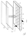
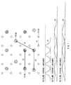
- FIG. 1 illustrates a configurational example of the lighting device according to the first embodiment of the present invention.
- the lighting device according to an embodiment of the present invention is disposed on the back surface side of a display panel 20, as the backlight 10 of the image display device, for example.
- the display panel 20 is, for example, a transmissive liquid-crystal display panel that displays an image by controlling the passing state of light emitted from the backlight 10, with liquid crystal molecules.
- the backlight 10 includes a light source section 11 and a diffuser 12.
- the light source section 11 has a housing 13 shaped like a box. On the bottom of the housing 13, a plurality of first light sources P1 and a plurality of second light sources P2 are arranged two-dimensionally in parallel.
- the diffuser 12 is disposed on the top surface side of the housing 13 integrally, so as to be at a predetermined distance h from the bottom of the housing 13.
- the diffuser 12 is provided to diffuse the light from the first light sources P1 and the second light sources P2, thereby equalizing the in-plane luminance distribution for each of predetermined partitioned sections 30.
- the plurality of first light sources P1 as a whole configure a first light source group.
- the plurality of second light sources P2 as a whole configure a second light source group.
- the first light source group and the second light source group are controlled for each of the predetermined partitioned sections 30.
- the partitioned sections 30 may not be regions formed by physically providing borders, and may be virtual partitioned sections in terms of control.
- FIG. 1 illustrates a state in which the partitioned sections are provided by virtual splitting with virtual splitting lines 31.
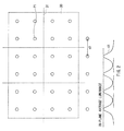
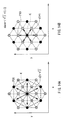
- FIG. 2 illustrates an arrangement of the first light sources P1, together with a luminance distribution 41 by the first light source P1.
- FIG. 3 illustrates an arrangement of the second light sources P2, together with a luminance distribution 42 by the second light source P2.
- FIG. 4 illustrates the arrangements of the first light sources P1 and the second light sources P2, together with the luminance distribution 41 by the first light source P1 and the luminance distribution 42 by the second light source P2.
- the luminance distributions 41 and 42 in these figures are distributions schematically illustrated at the predetermined distance h observed from a side-surface direction y1 in FIG. 1 (the surface of the diffuser 12).
- the first light source group and the second light source group are capable of being lit independently for each of the predetermined partitioned sections 30. Further, the first light source group and the second light source group are configured to be capable of being both lit at the same time for each of the predetermined partitioned sections 30.
- the plurality of first light sources P1 are arranged in a first array pattern so that when only the first light source group is lit as a whole, an in-plane luminance distribution at the predetermined distance h becomes uniform.
- the plurality of second light sources P2 are arranged in a second array pattern different from the first array pattern, so that when only the second light source group is lit as a whole, an in-plane luminance distribution at the predetermined distance h becomes uniform.
- the present embodiment is configured such that the array patterns of the first light source P1 and the second light source P2 are optimized and the diffuser 12 is disposed at the predetermined distance h, so that the light flux density of the light emitted from the individual light source elements of the first light source P1 and the second light source P2 is an approximately uniform light flux distribution on a plane at the predetermined distance h.
- the plurality of first light sources P1 are spaced approximately evenly at first arrangement intervals d1.
- the plurality of second light sources P2 is are spaced approximately evenly at second arrangement intervals d2 different from the first arrangement intervals d1.
- the second arrangement interval d2 is larger than the first arrangement interval d1.
- the first light source P1 and the second light source P2 are configured to respectively have light distributions different from each other. Specifically, the luminance distribution 41 by one first light source P1 is narrower than the luminance distribution 42 by one second light source P2, in terms of the spread in a horizontal direction (XY directions in FIG. 1 ).
- Such a difference in the luminance distribution may be realized by providing a condensing means (e.g., convex lens) or a light diffusion means (e.g., concave lens) on the light outgoing side of the first light source P1 or the second light source P2 as appropriate.
- a condensing means e.g., convex lens
- a light diffusion means e.g., concave lens
- the condensing means e.g., convex lens
- the light diffusion means e.g., concave lens
- first light sources P1 are disposed in one partitioned section 30 .
- the number of the first light sources P1 disposed in one partitioned section 30 is not limited to this example and similarly, the number of the second light sources P2 disposed in one partitioned section 30 is not limited to one as in the case illustrated in the figure.
- luminance distribution patterns different from one another are obtained for the respective predetermined partitioned sections 30, by the first light source group and the second light source group where the respective light sources are arranged in the array patterns different from each other. Therefore, by using the first light source group and the second light source group complementarily to each other, lighting control is performed in a complexly linked manner, so that locally sufficient luminance is obtained even when the light sources are locally lit. Further, lighting control of suppressing the unnecessary spread of light locally may be performed.
- FIG. 5A illustrates the luminance distribution 41 by only the first light source P1
- FIG. 5B illustrates the luminance distribution 42 by the second light source 2.
- FIG. 5C schematically illustrates the luminance distribution by the combination of the first light source P1 and the second light source P2. As illustrated in FIG. 5C , the combination of the first light source P1 and the second light source P2 may increase the luminance locally, while suppressing the unnecessary spread of light locally.
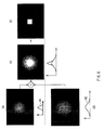
- Part (A) of FIG. 6 illustrates, in a case where this lighting device is used as the backlight 10 of the image display device, an in-plane luminance distribution image at the predetermined distance h when only the first light source P1 in a central area of the screen is caused to emit light.
- Part (B) of FIG. 6 illustrates an in-plane luminance distribution image at the predetermined distance h when only the second light source P2 in the central area of the screen is caused to emit light.
- Part (C) of FIG. 6 illustrates an in-plane luminance distribution image at the predetermined distance h when both of the first light source P1 and the second light source P2 in the central area of the screen are caused to emit the light.
- Combining the first light source P1 and the second light source P2 as illustrated in Part (C) of FIG. 6 may put only the central area of the screen in a state of locally high luminance.
- image display of white display in only the central area of the screen as illustrated, for example, in Part (D) of FIG. 6 may be well performed.
- the backlight 10 in the present embodiment will be described in comparison with a direct-lighting backlight employing a partitioning drive system in the past. Further, a case of use as a backlight of a transmissive liquid-crystal display panel will be described below by way of example.
- contrast may be defined as a ratio A/B that is a ratio between the brightest display luminance A and the darkest display luminance B.
- the control with the use of the backlight of partial light-quantity adjustment function type is proposed.
- the control method when a part to be displayed as an image in the liquid crystal panel is dark, the amount of light emission of blocks of backlight in the position corresponding to the part to be displayed as an image is reduced by dimming and thereby darkness is achieved, and at the same time, control is performed so that the amount of transmitted light of the display panel in the part to be displayed as an image is increased in a direction opposite to the direction of the dimming of the blocks. Therefore, as the entire display device, correction to realize correct reproduction of the brightness (darkness) to be originally displayed is performed, and thereby intended image display luminance is obtained.
- the light-quantity control function of the light sources themselves bears part of the display function of the liquid crystal panel. That is, the dark state is displayed by not only the shutter function of the liquid crystal panel but also the dimming function of the backlight that may be regarded as a self-luminous display body, and the shutter function and the dimming function cooperate to share the burden, and thereby a desired image display luminance is reproduced.
- the number of partitioned blocks of backlight is generally small compared to the pixel of the liquid crystal display panel, so the space frequency of the partitioned block is low.
- this backlight corresponds to a case in which all the light emitting sources are lit simultaneously.
- illumination is provided not only by the light of a part on its back surface, but the brightness of the specific point is determined, based on integration of the light from all the surroundings of the specific point, such as the light added upon reaching after emitted by the light sources disposed around the back surface and an added component by the arrival of the light from outside farther than the surroundings.
- the source of luminance is a diffusing light source and thus, when a special condensing lens or the like is not provided, the light exhibits a light distribution shape spread like a hazy moon having the center on the light emitting source. For this reason, the light scatters toward the surroundings of the light source and thereby a central part immediately above the source of luminance and originally closest to the source of luminance does not become bright on the surface of the diffuser, as compared to the case where all the sources of luminance are lit.
- the luminance ratio at the time of local lighting with respect to the overall lighting is in a level of falling within a range of about 0.2 to 0.5 experimentally.
- This luminance ratio will not be 1.0, unless special operation such as putting the display panel in contact with the light source is performed. Therefore, in the backlight employing the partitioning drive system in the past, the brightness is insufficient for a normal light distribution state that is achieved when only one certain block is lit. When attention is paid to a certain particular image point, this point is not sufficiently lit by lighting on the back surface of this point by an ordinary way of lighting the block.
- the light spreads and thus has a region referred to as a spread range.
- this spread range is wide, the following disadvantage arises.
- an image that is "a certain particular image point desired to have luminance” an image that is a window signal in which a certain particular circular range is assumed to be 100% white and its surroundings are displayed as black (see Part (D) of FIG. 6 ).
- the correct display form of this signal is desired to be black display in its surroundings, but results in a state in which due to the physical property referred to as the above-mentioned spread of the light, unnecessary light spreads and reaches points which are located around the 100% white range and in which brightness is undesired.
- the amount of light is short.
- the backlight 10 of the present embodiment has been proposed, in view of the situations described in the above items 1 through 5, in particular, by focusing on the situations described in the above items 4 and 5.
- the backlight 10 of the present embodiment prevents such a state that the lighting is not local as in the cases described in the above items 4 and 5.
- the backlight 10 of the present embodiment is allowed to effectively illuminate portions to be illuminated, while preventing the spread (sprawling) of light.
- the backlight 10 of the present embodiment may obtain a pseudo lens effect which is as if the light flux density distribution of the light from the light source is controlled between the condensed state and the diffused state by a variable lens.
- the plurality of light sources different in spatial light-emission range and intensity are caused to emit light by being distinguished according to the type of light-source arrangement pitch, and they are combined, so that the ultimate luminance distribution is obtained.
- the first light source P1 and the second light source P2 employing the independent partitioning drive system are combined, and their lighting levels are changed, so that a light-quantity distribution effect like control between the condensed state and the diffused state by a lens may be obtained (see FIG. 5C ).
- the lighting of the first light source group and the second light source group whose array patterns of the light sources are different from each are controlled for each of the predetermined partitioned sections 30. Therefore, the luminance distribution patterns varying between the first light source group and the second light source group may be obtained for each of the predetermined partitioned sections 30.
- the luminance distribution patterns different from each other are used complementarily to each other and thereby the lighting of the first light source group and the second light source group is controlled in a complexly linked manner, so that locally sufficient luminance may be obtained even when the light sources are lit locally. Further, lighting that suppresses the unnecessary spread of light locally may be performed.
- the lighting device according to the present embodiment is used as the backlight 10 and thus, the unnecessary spread of light is suppressed locally and also sufficient luminance may be obtained. As a result, even when, for example, image display with a partially varying resolution within one screen is carried out, image display with a high resolution may be performed while power consumption is reduced.
- the entire configuration of the lighting device in the present embodiment is similar to that in FIG. 1 .
- a plurality of third light sources P3 are arranged two-dimensionally in parallel.
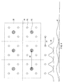
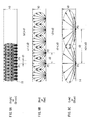
- FIG. 7 illustrates the layout of the first light sources P1, the second light sources P2 and the third light sources P3, together with the luminance distribution 41 by the first light source P1, the luminance distribution 42 by and the second light source P2 and a luminance distribution 43 by the third light source P3.
- Each of these luminance distributions 41, 42 and 43 is a schematically illustrated luminance distribution at the predetermined distance h (the surface of the diffuser 12) observed from the side-surface direction y1 in FIG. 1 .
- the plurality of third light sources P3 as a whole configure a third light source group.
- the lighting of the third light source group is controlled for each of the predetermined partitioned sections 30, in a manner similar to the first light source group and the second light source group.
- three light source groups made up of the first through third light source groups in total are configured to be lit at the same time for each of the predetermined partitioned sections 30.
- the plurality of third light sources P3 are arranged in a third array pattern, so that the in-plane luminance distribution at the predetermined distance h when only the third light source group is lit becomes uniform.
- the array patterns of the first light source P1, the second light source P2 and the third light source P3 are optimized, and the diffuser 12 is disposed at the predetermined distance h, so that the light flux density of the light emitted from the individual light source elements of the first light source P1, the second light source P2 and the third light source P3 becomes an approximately uniform flux distribution on a plane at the predetermined distance h.
- the plurality of third light sources P3 are spaced approximately evenly at third arrangement intervals d3 different from the first arrangement intervals d1 and the second arrangement intervals d2.
- the third arrangement interval d3 is larger than the second arrangement interval d2.
- the first light sources P1, the second light sources P2 and the third light sources P3 are arranged to have mutually different light distributions.
- the luminance distribution 41 by one first light source P1 is narrower than the luminance distribution 42 by one second light source P2 in terms of spread in the horizontal direction (XY directions in FIG. 1 ).
- the luminance distribution 43 by one third light source P3 is wider than the luminance distribution 42 by one second light source P2, in terms of spread in the horizontal direction (XY directions in FIG. 1 ).
- a condensing means (convex lens 15) to condense the light is disposed on the light outgoing side of the first light source P1 as illustrated in FIG. 9A .
- a light diffusion means (concave lens 14) is disposed on the light outgoing side of the third light source P3 as illustrated in FIG. 9C .
- FIG. 9A schematically illustrates a diffused state of rays by the first light source P1
- FIG. 9B schematically illustrates a diffused state of rays by the second light source P2
- FIG. 9C schematically illustrates a diffused state of rays by the third light source P3.
- the predetermined distance h is h3.
- FIG. 8A through FIG. 8C schematically illustrate a relation between the light source interval to achieve a uniform luminance distribution on the plane at the predetermined distance and the diffused state of rays.
- FIG. 8A schematically illustrates a case in which the interval between the light sources and the diffused state of rays are narrow.
- FIG. 8B schematically illustrates a case in which the interval between the light sources and the diffused state of rays are intermediate.
- FIG. 8C schematically illustrates a case in which the interval between the light sources and the diffused state of rays are wide.
- FIG. 8A through FIG. 8C illustrate the states where the distances h to obtain a uniform luminance distribution vary among the intervals between the light sources. Meanwhile, the states illustrated in FIG. 9A through FIG.
- FIG. 9C correspond to the states in FIG. 8A through FIG. 8C when the respective distances are normalized to be the same distance h3, respectively.
- the intensity of the light emitted by the light sources is observed from every spatial direction and drawn.
- perfectly diffused light Lambertian
- the lighting device according to the present embodiment is used as the backlight 10 of the image display device, for example, the following application methods are conceivable.
- a method of properly using the light source groups to use according to the spatial frequency of an image displayed in the image display device.
- the first light source P1 with the narrow arrangement interval is used as a green (Green) light source ( FIG. 9A )
- the third light source P3 with the wide arrangement interval is used as a blue (Blue) light source ( FIG. 9C ).
- the second light source P2 with the intermediate arrangement interval is used a red (Red) light source ( FIG. 9B ).
- the number of light source groups is not limited to three, and a larger number of light source groups may be provided.
- the lighting device according to the third embodiment of the present invention will be described.
- the entire configuration of the lighting device in the present embodiment is similar to that in FIG. 1 .
- the array pattern of the first light source P1 or the second light source P2 is different.
- the first light sources P1 are positioned as if they are at the vertices of an approximately square shape.
- the array pattern of the light sources (in the following, the light sources of an arbitrary light source group will be represented by P) is not limited to such a pattern.
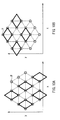
- FIG. 10A illustrates a first arrangement example of the light sources P
- FIG. 10B illustrates a second arrangement example, in the lighting device according to the present embodiment.
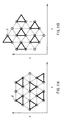
- FIG. 11A illustrates a third arrangement example
- FIG. 11B illustrates a fourth arrangement example.
- FIG. 10A and FIG. 10B each illustrate an example in which the light sources P are disposed at the vertices of the rhombus.
- FIG. 11A and FIG. 11B each illustrate an example in which the light sources P are disposed at the vertices of the almost regular triangle.
- the type of the arrangement interval d between the adjacent light sources is not only one, and may be plural.
- the base and other two sides are different in length and thus, there are two types of arrangement interval.
- the lighting device according to the fourth embodiment of the present invention will be described.
- the entire configuration of the lighting device in the present embodiment is similar to that in FIG. 1 .
- the array pattern of the first light source P1 or the second light source P2 is different.
- the first light source P1 or the second light source P2 may be a combined light source made up of densely arranged two or more light sources. Further, the plurality of first light sources P1 or the plurality of second light sources P2 may be arranged so that the interval between the emission barycenters of the respective combined light sources is the first arrangement interval d1 or the second arrangement interval d2.
- FIG. 12A illustrates an example of such a combined light source.
- densely arranged three light sources P11, P12 and P13 combined serve as one combined light source.
- such a combined light source is referred to as a "light source cluster" Q1.
- a mutual distance among the three light sources P11, P 12 and P 13 forming the light source cluster Q1 is Ln.
- a synthetic emission barycenter in the light source cluster Q1 is regarded as a light source center q.
- FIG. 12B illustrates an arrangement example in which a plurality of light source clusters Q1 in FIG. 12A are arranged two-dimensionally.
- the arrangement is made so that when the mutual distance between the emission barycenters (the light source centers q) of the adjacent light source clusters Q1 is Lf, there is realized, 2Ln ⁇ Lf and Lf is assumed to be the arrangement interval between the light source clusters Q1.
- an average of these distances may be the arrangement interval between the light source clusters Q1.
- the lighting device according to the fifth embodiment of the present invention will be described.
- the entire configuration of the lighting device in the present embodiment is similar to that in FIG. 1 .
- the array pattern of the first light source P1 or the second light source P2 is different.
- FIG. 13 illustrates an example of the arrangement of the light sources in the lighting device according to the present embodiment.
- FIG. 14A and FIG. 14B illustrate an arrangement interval between the light sources, by focusing on a central light source K in the example of the arrangement of the light sources illustrated in FIG. 13 .
- the present embodiment relates to a processing method of the lighting control of the backlight 10 in a case in which the lighting device illustrated in FIG. 1 is used as the backlight 10 of an image display device.
- FIG. 15 illustrates a configurational example of a control circuit of the image display device in the present embodiment.
- This image display device includes an image processing section 51, a panel driving section 52, a light-source control section 53 and a light-source drive section 54.
- Original image data of an image to be displayed on the display panel 20 is inputted.
- the light-source control section 53 controls the light-source drive section 54, according to the inputted original image data, and controls the lighting of the light sources (the first light source P1 and the second light source P2) in the backlight 10.
- the image processing section 51 corrects the inputted original image data based on lighting image data of light sources determined by the light-source control section 53, and performs driving control of the panel driving section 52 so that the image after the correction is displayed on the display panel 20.
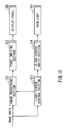
- FIG. 16 illustrates an example of the lighting control of the backlight 10 in the image display device according to the present embodiment.
- steps S1 to S7 are processing by the light-source control section 53
- a step S8 is processing by the image processing section 51
- a step S9 is processing of the display panel 20.
- a light source group which has the light sources having a wide spread range of light and arranged in a coarse array pattern with a long arrangement interval, relatively, is assumed to be A. Further, a light source group, which has the light sources having a narrow spread range of light and arranged in a fine array pattern with a short arrangement interval, relatively, is assumed to be B.
- the light source group A corresponds to the second light source group in the first embodiment described above.
- the light source group B corresponds to the first light source group in the first embodiment described above.
- W A W B
- the amount of light emission of each light source group is 1:1, so that the mutually same ratio is achieved.
- the ratio of electric power controlled and shared in each light source group may be different from those in other light source groups, the amount of light emission may not be necessarily 1:1.
- the light-source control section 53 distributes a light emission level to each light source group (step S1).
- the light emission level is simply halved for the light source group A and the light source group B.
- the processing by this light-source control section 53 is carried out for each of the predetermined partitioned sections 30 according to the inputted image data.
- halving the light emission level means as follows.
- in-plane average luminance in a case where only the light source group A as a whole is lit is assumed to be Xa
- in-plane average luminance in a case where only the light source group B as a whole is lit is assumed to be (1-Xa)
- the lighting is performed so that the level of the in-plane average luminance at a predetermined distance h in a case where both of the light source group A and the light source group B are lit concurrently on the whole becomes 1.
- halving the light emission level is equivalent to a case where the amount of light emission of the light source group A is 1/2, the amount of light emission of the light source group B is 1/2, and the total amount of light emission of both groups is 1.
- the total amount of light emission mentioned here may be proportional to an Average Picture Level (APL) of a full-screen.
- APL Average Picture Level
- Peak luminance may be used and thus, there are many choices.
- the size of the original image is assumed to be 1, a synthesis obtained by adding two images of 0.5 times the original image together may be assumed.
- one of the images of 0.5 times is subjected to partitioning-driving backlighting by the light source group A, and the other is subjected to partitioning-driving backlighting by the light source group B.
- the light source group A and the backlight of B have different spatial light-emission resolutions.
- a synthetic light-emission pattern (a synthetic backlight image) C resulting from additive synthesis of the light emission pattern by the light source group A and the light emission pattern by the light source group B is determined by, for example, simple addition (step S6).
- the backlight 10 is lit based on this synthetic light-emission pattern C (step S7).
- the image processing section 51 performs processing of dividing the original image based on the synthetic light-emission pattern C (step S8), thereby computing an inversely corrected image for the synthetic light-emission pattern C, and displays the corrected image on the display panel 20 (step S9).
- the present embodiment relates to a processing method of the lighting control of the backlight 10 in a case where the lighting device illustrated in FIG. 1 is used as the backlight 10 of an image display device.
- the image display device in the present embodiment has a control circuit ( FIG. 15 ) similar to the above-described sixth embodiment.
- contents of the lighting control by the light-source control section 53 are partially different from the sixth embodiment. Only the part different from the sixth embodiment will be mainly described below.
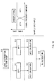
- FIG. 17 illustrates an example of the lighting control of the backlight 10 in the image display device according to the present embodiment. What is different from the lighting control in the sixth embodiment illustrated in FIG. 16 is the processing in step S1.
- the processing in step S1 there is performed such control that the light emitting level is simply halved for the light source group A and the light source group B.
- the distribution of the light emission level to each light source group is variable (step S1A).
- in-plane average luminance in a case where only the light source group A as a whole is lit is assumed to be Xa
- in-plane average luminance in a case where only the light source group B as a whole is lit is assumed to be (1-Xa)
- the lighting is performed so that the level of the in-plane average luminance at a predetermined distance h in a case where both of the light source group A and the light source group B are lit concurrently on the whole becomes 1.
- the lighting control of the light source group A and the light source group B is performed by using Xa as a variable value under a condition of 0 ⁇ Xa ⁇ 1.
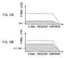
- Xa is caused to vary according to the spatial frequency of an image.
- Xa is caused to vary such that the higher the spatial frequency of the image is, the smaller the value of Xa is. This realizes such lighting control that the higher the spatial frequency of the image is, the larger the amount of light by the light source group B (the first light source group) having light sources with a short arrangement interval is, and the lower the spatial frequency of the image is, the smaller the amount of light by the light source group A (the second light source group) having light sources with a long arrangement interval is.
- FIG. 18 illustrates an example of level distribution processing (processing of calculating Xa) of distribution to each light source group by such variableness control.
- FIG. 19A illustrates an example of the signal level of the light source group A
- FIG. 19B illustrates an example of the signal level of the light source group B, when such variable control is performed.
- step S11 lowpass filter processing
- step S12 highpass filter processing
- step S12 highpass filter processing
- step S13 A luminance average of a full screen after the lowpass filter processing is performed
- APL2 A luminance average of the full screen after the highpass filter processing is performed
Landscapes
- Physics & Mathematics (AREA)
- Nonlinear Science (AREA)
- Mathematical Physics (AREA)
- Chemical & Material Sciences (AREA)
- Crystallography & Structural Chemistry (AREA)
- General Physics & Mathematics (AREA)
- Optics & Photonics (AREA)
- Liquid Crystal (AREA)
- Planar Illumination Modules (AREA)
- Devices For Indicating Variable Information By Combining Individual Elements (AREA)
- Circuit Arrangement For Electric Light Sources In General (AREA)
Applications Claiming Priority (1)
| Application Number | Priority Date | Filing Date | Title |
|---|---|---|---|
| JP2010112496A JP2011243330A (ja) | 2010-05-14 | 2010-05-14 | 照明装置および画像表示装置 |
Publications (2)
| Publication Number | Publication Date |
|---|---|
| EP2386902A2 true EP2386902A2 (de) | 2011-11-16 |
| EP2386902A3 EP2386902A3 (de) | 2012-01-18 |
Family
ID=44117649
Family Applications (1)
| Application Number | Title | Priority Date | Filing Date |
|---|---|---|---|
| EP11164178A Withdrawn EP2386902A3 (de) | 2010-05-14 | 2011-04-28 | Beleuchtungsvorrichtung und Bildanzeigevorrichtung |
Country Status (5)
| Country | Link |
|---|---|
| US (1) | US20110280002A1 (de) |
| EP (1) | EP2386902A3 (de) |
| JP (1) | JP2011243330A (de) |
| CN (1) | CN102313199A (de) |
| TW (1) | TW201142424A (de) |
Families Citing this family (22)
| Publication number | Priority date | Publication date | Assignee | Title |
|---|---|---|---|---|
| JP2013143239A (ja) * | 2012-01-10 | 2013-07-22 | Sharp Corp | Ledバックライト装置および液晶表示装置 |
| JP2013157255A (ja) * | 2012-01-31 | 2013-08-15 | Sharp Corp | 照明装置及び表示装置 |
| KR102092048B1 (ko) * | 2012-11-23 | 2020-03-24 | 삼성디스플레이 주식회사 | 백라이트 유닛과 이를 포함하는 표시 장치 |
| KR102098590B1 (ko) * | 2012-12-11 | 2020-04-09 | 삼성전자주식회사 | 발광모듈 및 이를 구비한 면 조명장치 |
| US9482410B2 (en) | 2012-12-11 | 2016-11-01 | Samsung Electronics Co., Ltd. | Light emitting module and surface lighting device having the same |
| USD715799S1 (en) | 2012-12-21 | 2014-10-21 | Bloomberg Finance L.P. | Flat panel display |
| JP6108881B2 (ja) * | 2013-03-05 | 2017-04-05 | シャープ株式会社 | 照明装置 |
| JP2014174334A (ja) * | 2013-03-08 | 2014-09-22 | Canon Inc | 画像表示装置及びその制御方法 |
| CN105049836B (zh) * | 2015-07-08 | 2017-03-01 | 四川长虹电器股份有限公司 | Led电视背光分区快速检查方法 |
| JP6728931B2 (ja) * | 2016-04-21 | 2020-07-22 | セイコーエプソン株式会社 | 光源装置およびプロジェクター |
| JP2017212384A (ja) | 2016-05-27 | 2017-11-30 | ソニー株式会社 | 発光素子及び表示装置 |
| CN106610548B (zh) * | 2017-02-27 | 2019-11-05 | 京东方科技集团股份有限公司 | 一种显示面板、显示装置及调节亮度的方法 |
| JP7146748B2 (ja) | 2017-05-15 | 2022-10-04 | ソニーグループ株式会社 | 照明装置、および表示装置 |
| JP7307236B2 (ja) * | 2017-10-11 | 2023-07-11 | 株式会社ジャパンディスプレイ | 表示装置 |
| CN109407397A (zh) * | 2018-10-30 | 2019-03-01 | 武汉华星光电技术有限公司 | 背光模组及显示装置 |
| WO2021051347A1 (zh) * | 2019-09-19 | 2021-03-25 | 瑞仪光电(苏州)有限公司 | 光源结构、背光模组及显示装置 |
| CN112422841B (zh) * | 2020-11-09 | 2023-01-20 | 上海原能细胞生物低温设备有限公司 | 图像补偿方法、装置、计算机设备和存储介质 |
| KR102838122B1 (ko) * | 2021-02-26 | 2025-07-25 | 삼성전자주식회사 | 디스플레이 장치 및 그 광원 장치 |
| JP2023005241A (ja) * | 2021-06-28 | 2023-01-18 | 船井電機株式会社 | 表示装置およびバックライト装置 |
| CN118339507A (zh) | 2021-12-15 | 2024-07-12 | 株式会社日本显示器 | 显示装置 |
| CN119948291A (zh) * | 2022-08-23 | 2025-05-06 | 美蓓亚三美株式会社 | 面状照明装置 |
| CN116009310B (zh) * | 2023-02-23 | 2024-07-09 | 业成光电(深圳)有限公司 | 区域调光的背光模块及显示器 |
Citations (3)
| Publication number | Priority date | Publication date | Assignee | Title |
|---|---|---|---|---|
| JP2007141737A (ja) | 2005-11-21 | 2007-06-07 | Sharp Corp | 照明装置、液晶表示装置、照明装置の制御方法、照明装置制御プログラム、および記録媒体 |
| JP2008097896A (ja) | 2006-10-10 | 2008-04-24 | Sharp Corp | バックライトユニット及び該ユニットを備える画像表示装置 |
| JP2010112496A (ja) | 2008-11-07 | 2010-05-20 | Nok Corp | 密封装置 |
Family Cites Families (5)
| Publication number | Priority date | Publication date | Assignee | Title |
|---|---|---|---|---|
| DE102006002275A1 (de) * | 2005-01-19 | 2006-07-20 | Osram Opto Semiconductors Gmbh | Beleuchtungseinrichtung |
| US8123375B2 (en) * | 2005-11-18 | 2012-02-28 | Cree, Inc. | Tile for solid state lighting |
| JP4151717B2 (ja) * | 2006-07-21 | 2008-09-17 | ソニー株式会社 | 光源モジュール、光源装置及び液晶表示装置 |
| KR100809264B1 (ko) * | 2006-07-25 | 2008-03-03 | 삼성전기주식회사 | 면광원 장치 및 이를 구비하는 백라이트 유닛 |
| EP2364458B1 (de) * | 2008-11-14 | 2016-05-04 | Dolby Laboratories Licensing Corporation | Angepasstes psfs unter verwendung geclusterter lichtquellen |
-
2010
- 2010-05-14 JP JP2010112496A patent/JP2011243330A/ja active Pending
-
2011
- 2011-03-23 TW TW100109962A patent/TW201142424A/zh unknown
- 2011-04-04 US US13/079,284 patent/US20110280002A1/en not_active Abandoned
- 2011-04-28 EP EP11164178A patent/EP2386902A3/de not_active Withdrawn
- 2011-05-09 CN CN2011101175870A patent/CN102313199A/zh active Pending
Patent Citations (3)
| Publication number | Priority date | Publication date | Assignee | Title |
|---|---|---|---|---|
| JP2007141737A (ja) | 2005-11-21 | 2007-06-07 | Sharp Corp | 照明装置、液晶表示装置、照明装置の制御方法、照明装置制御プログラム、および記録媒体 |
| JP2008097896A (ja) | 2006-10-10 | 2008-04-24 | Sharp Corp | バックライトユニット及び該ユニットを備える画像表示装置 |
| JP2010112496A (ja) | 2008-11-07 | 2010-05-20 | Nok Corp | 密封装置 |
Also Published As
| Publication number | Publication date |
|---|---|
| TW201142424A (en) | 2011-12-01 |
| EP2386902A3 (de) | 2012-01-18 |
| US20110280002A1 (en) | 2011-11-17 |
| CN102313199A (zh) | 2012-01-11 |
| JP2011243330A (ja) | 2011-12-01 |
Similar Documents
| Publication | Publication Date | Title |
|---|---|---|
| EP2386902A2 (de) | Beleuchtungsvorrichtung und Bildanzeigevorrichtung | |
| US9411088B2 (en) | Illumination module | |
| US8419257B2 (en) | Display apparatus and planar illumination apparatus | |
| KR100852579B1 (ko) | 면 조명 장치 및 그것을 이용한 액정 표시 장치 | |
| CN100529899C (zh) | 背后照明装置 | |
| US7270461B2 (en) | Backlight unit and liquid crystal display utilizing the same | |
| US8104945B2 (en) | Backlight unit implementing local dimming for liquid crystal display device | |
| CN101162299B (zh) | 具有扩大的表观尺寸的方法、介质和显示系统 | |
| US20070024772A1 (en) | Display with sub-region backlighting | |
| US20110227895A1 (en) | Backlight unit, illumination device, and display device | |
| JP2007286627A (ja) | 液晶表示装置用のバックライトユニット | |
| US20080106512A1 (en) | Light source arrangement for backlighting display devices | |
| US8400397B2 (en) | Backlighting system and display device | |
| US8113703B2 (en) | Dual-layer light guide structure for LED-based lighting device | |
| JP2009224030A (ja) | Ledバックライトユニットおよび液晶表示装置 | |
| JP2007073295A (ja) | 直下式バックライト装置及び画像表示装置 | |
| US20100231827A1 (en) | Liquid crystal display apparatus and illuminating apparatus therefor | |
| JP4605465B2 (ja) | バックライトモジュールと液晶表示装置 | |
| TW202001847A (zh) | 顯示裝置及其驅動方法 | |
| JP2006227244A (ja) | 表示装置及びこれを用いたプロジェクタ | |
| US9829744B2 (en) | High performance seamless light emitting diode illuminated display | |
| KR100903436B1 (ko) | 디스플레이 장치 | |
| JP2008134525A (ja) | 液晶表示装置 | |
| JP2017062876A (ja) | 光源装置 | |
| JP2006215249A (ja) | 液晶表示装置用バックライト及び液晶表示装置 |
Legal Events
| Date | Code | Title | Description |
|---|---|---|---|
| 17P | Request for examination filed |
Effective date: 20110516 |
|
| AK | Designated contracting states |
Kind code of ref document: A2 Designated state(s): AL AT BE BG CH CY CZ DE DK EE ES FI FR GB GR HR HU IE IS IT LI LT LU LV MC MK MT NL NO PL PT RO RS SE SI SK SM TR |
|
| AX | Request for extension of the european patent |
Extension state: BA ME |
|
| PUAI | Public reference made under article 153(3) epc to a published international application that has entered the european phase |
Free format text: ORIGINAL CODE: 0009012 |
|
| PUAL | Search report despatched |
Free format text: ORIGINAL CODE: 0009013 |
|
| AK | Designated contracting states |
Kind code of ref document: A3 Designated state(s): AL AT BE BG CH CY CZ DE DK EE ES FI FR GB GR HR HU IE IS IT LI LT LU LV MC MK MT NL NO PL PT RO RS SE SI SK SM TR |
|
| AX | Request for extension of the european patent |
Extension state: BA ME |
|
| RIC1 | Information provided on ipc code assigned before grant |
Ipc: G02F 1/13357 20060101AFI20111209BHEP |
|
| STAA | Information on the status of an ep patent application or granted ep patent |
Free format text: STATUS: THE APPLICATION HAS BEEN WITHDRAWN |
|
| 18W | Application withdrawn |
Effective date: 20130424 |