EP2386871B1 - Radarvorrichtung - Google Patents
Radarvorrichtung Download PDFInfo
- Publication number
- EP2386871B1 EP2386871B1 EP11164914.1A EP11164914A EP2386871B1 EP 2386871 B1 EP2386871 B1 EP 2386871B1 EP 11164914 A EP11164914 A EP 11164914A EP 2386871 B1 EP2386871 B1 EP 2386871B1
- Authority
- EP
- European Patent Office
- Prior art keywords
- antenna
- synthesized
- signal
- baseband signal
- array
- Prior art date
- Legal status (The legal status is an assumption and is not a legal conclusion. Google has not performed a legal analysis and makes no representation as to the accuracy of the status listed.)
- Not-in-force
Links
- 239000011159 matrix material Substances 0.000 claims description 92
- 238000012937 correction Methods 0.000 claims description 59
- 230000005540 biological transmission Effects 0.000 claims description 48
- 238000012545 processing Methods 0.000 claims description 37
- 239000013598 vector Substances 0.000 claims description 35
- 238000000034 method Methods 0.000 claims description 26
- 238000001514 detection method Methods 0.000 claims description 25
- 230000015572 biosynthetic process Effects 0.000 claims description 18
- 238000003786 synthesis reaction Methods 0.000 claims description 18
- 239000000523 sample Substances 0.000 claims description 14
- 230000002194 synthesizing effect Effects 0.000 claims description 10
- 230000014509 gene expression Effects 0.000 description 61
- 238000010586 diagram Methods 0.000 description 8
- 238000001228 spectrum Methods 0.000 description 8
- 230000017105 transposition Effects 0.000 description 7
- 238000009499 grossing Methods 0.000 description 5
- 230000015654 memory Effects 0.000 description 5
- 206010057239 Post laminectomy syndrome Diseases 0.000 description 4
- 238000000354 decomposition reaction Methods 0.000 description 3
- 238000005259 measurement Methods 0.000 description 3
- 238000004364 calculation method Methods 0.000 description 2
- 230000000694 effects Effects 0.000 description 2
- 230000006870 function Effects 0.000 description 2
- 230000008569 process Effects 0.000 description 2
- 230000004044 response Effects 0.000 description 2
- 239000000654 additive Substances 0.000 description 1
- 230000000996 additive effect Effects 0.000 description 1
- 230000008859 change Effects 0.000 description 1
- 238000011161 development Methods 0.000 description 1
- 239000000203 mixture Substances 0.000 description 1
- 230000008520 organization Effects 0.000 description 1
- 238000005070 sampling Methods 0.000 description 1
Images


Classifications
-
- G—PHYSICS
- G01—MEASURING; TESTING
- G01S—RADIO DIRECTION-FINDING; RADIO NAVIGATION; DETERMINING DISTANCE OR VELOCITY BY USE OF RADIO WAVES; LOCATING OR PRESENCE-DETECTING BY USE OF THE REFLECTION OR RERADIATION OF RADIO WAVES; ANALOGOUS ARRANGEMENTS USING OTHER WAVES
- G01S13/00—Systems using the reflection or reradiation of radio waves, e.g. radar systems; Analogous systems using reflection or reradiation of waves whose nature or wavelength is irrelevant or unspecified
- G01S13/02—Systems using reflection of radio waves, e.g. primary radar systems; Analogous systems
- G01S13/06—Systems determining position data of a target
- G01S13/42—Simultaneous measurement of distance and other co-ordinates
-
- G—PHYSICS
- G01—MEASURING; TESTING
- G01S—RADIO DIRECTION-FINDING; RADIO NAVIGATION; DETERMINING DISTANCE OR VELOCITY BY USE OF RADIO WAVES; LOCATING OR PRESENCE-DETECTING BY USE OF THE REFLECTION OR RERADIATION OF RADIO WAVES; ANALOGOUS ARRANGEMENTS USING OTHER WAVES
- G01S13/00—Systems using the reflection or reradiation of radio waves, e.g. radar systems; Analogous systems using reflection or reradiation of waves whose nature or wavelength is irrelevant or unspecified
- G01S13/88—Radar or analogous systems specially adapted for specific applications
- G01S13/89—Radar or analogous systems specially adapted for specific applications for mapping or imaging
-
- G—PHYSICS
- G01—MEASURING; TESTING
- G01S—RADIO DIRECTION-FINDING; RADIO NAVIGATION; DETERMINING DISTANCE OR VELOCITY BY USE OF RADIO WAVES; LOCATING OR PRESENCE-DETECTING BY USE OF THE REFLECTION OR RERADIATION OF RADIO WAVES; ANALOGOUS ARRANGEMENTS USING OTHER WAVES
- G01S7/00—Details of systems according to groups G01S13/00, G01S15/00, G01S17/00
- G01S7/02—Details of systems according to groups G01S13/00, G01S15/00, G01S17/00 of systems according to group G01S13/00
- G01S7/40—Means for monitoring or calibrating
Definitions
- Some detection and ranging apparatuses may use a technology which combines a transmission sensor array including a plurality of transmission sensor elements and a reception sensor array including a plurality of reception sensor elements to effectively enlarge the aperture of the reception sensor array.
- a radar apparatus will be described as a concrete example of a detection and ranging apparatus.
- the technology described above may be called holographic aperture synthesis, holograph, aperture synthesis, synthesis aperture or the like.
- a radar apparatus using aperture synthesis radiates a probe signal modulated by an arbitrary method from a plurality of transmission sensor elements at time slots assigned to transmission sensors by time division multiplexing, for example.
- An echo signal caused by the reflection of the probe signal by a detection target is received by a plurality of reception sensor elements.
- the radar apparatus synthesizes the reception signals acquired at the time slots assigned to the transmission sensors.
- the radar apparatus can have an increased number of effective reception sensor elements and can detect an increased number of targets, thus improving the angular resolution.
- a radar apparatus using aperture synthesis will be called an aperture synthesis radar.
- a sensor element and a sensor array are not distinguished from an antenna (element) and an array antenna, respectively. Reference may be made to Japanese Laid-open Patent Publication No. 2009-80024 and U.S. Patent No. 7196656 .
- the present invention provides a radar apparatus as set out in appended Claim 1, and a target detection method as set out in Claim 4. Optional features are set out in remaining claims.
- a radar apparatus which uses FMCW (Frequency Modulated Continuous Wave) as a probe signal (hereinafter simply called a radar apparatus) will be described.
- a radar apparatus according to an embodiment may be mounted in a vehicle, for example.
- a radar apparatus according to an embodiment does not limit the object, apparatus and system in which the radar apparatus is to be mounted.
- the following embodiments are given for illustration purpose only, and the present disclosure is not limited by the configurations of the following embodiments.
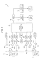
- FIG. 1 is a block diagram illustrating a configuration example of a radar apparatus according to an embodiment.
- a radar apparatus 1 includes, as illustrated in FIG. 1 , an array antenna 11, a low noise amplifier (hereinafter LNA) 12, a power amplifier (hereinafter HPA) 13, a mixer (MIX in FIG. 1 ) 14, an analog/digital (hereinafter A/D) converter 15, a signal processing unit 20, an oscillating module (OSC MODULE in FIG. 1 ) 17, a CPU (Central Processing Unit) 16, and a switch controller (SW CONTROLLER in FIG. 1 ) 18.
- LNA low noise amplifier
- HPA power amplifier
- A/D analog/digital converter
- signal processing unit 20 an oscillating module
- OSC MODULE oscillating module
- CPU Central Processing Unit
- SW CONTROLLER switch controller
- the oscillating module 17 may have a baseband oscillator and a high-frequency voltage control oscillator, for example, and outputs a system reference signal as a result of the operations of the oscillators. More specifically, a reference signal output from the baseband oscillator is fed to the high-frequency voltage control oscillator, and the reference signal is used to generate a frequency-modulated high-frequency signal as a system reference signal from the high-frequency voltage control oscillator.
- the reference signal may be ramp waves.
- a current control type oscillator may be used.
- the oscillating module 17 may be a module being capable of digitally and directly generating an FMCW signal, such as a DDS (Direct Digital Synthesizer).
- the HPA 13 is provided in a processing line corresponding to a transmission antenna. According to the example in FIG. 1 , because two antennas of A T1 and A T2 are used as transmission antennas, two HPAs 13 (HPA 131 and HPA 132) are provided. Each of the HPAs 13 amplifies a system reference signal output from the oscillating module 17, and the amplified signal is output as a probe signal for target detection from an antenna selected as a transmission antenna.
- the array antenna 11 has N antenna (sensor) elements which are disposed in different space positions.
- the array antenna 11 forms a ULA (Uniform Linear Array, or simply called Uniform Array hereafter) antenna in which the antenna elements are aligned straight at equal intervals.
- ULA Uniform Linear Array, or simply called Uniform Array hereafter
- two antenna elements at both ends of the antenna elements aligned straight are shared for transmission and reception, and the other antenna elements are only used for reception.
- an antenna element to be shared for transmission and reception will be called a shared antenna A R1/T1 or shared antenna A RN/T2 .
- a shared antenna may be switched for transmission or reception by a switch 19 by time division.
- Antenna elements which operate as reception antennas will be referred to as A R1 to A RN
- antenna elements which operate as transmission antennas will be referred to as A T1 and A T2 .
- the radar apparatus 1 uses an aperture enlarging technology which increases the number of effective reception antennas with a combination of a plurality of transmission antennas and a plurality of reception antennas.
- the switch 19 switches the shared antenna between the use for transmission and the use for reception in accordance with a control signal from the switch controller 18. More specifically, the switch 191 switches the shared antenna A R1/T1 between the connection to the HPA 131 and the connection to the LNA 121. If the shared antenna A R1/T1 is connected to the HPA 131, it operates as the transmission antenna A T1 . If the shared antenna A R1/T1 is connected to the LNA 121, it operates as the reception antenna A R1 . In the same manner, the switch 192 switches the shared antenna A RN/T2 between the connection to the HPA 132 and the connection to the LNA 12N. If the shared antenna A PN/T2 is connected to the HPA 132, it operates as the transmission antenna A T2 . If the shared antenna A RN/T2 is connected to the LNA 12N, it operates as the reception antenna A RN .
- the switch controller 18 controls the switching timing of the switch 19 in accordance with transmission cycle information (P/Q) transmitted from the CPU16 and a cycle T f (which may be also set by the CPU16) of a reference signal output from a baseband oscillator of the oscillating module 17.
- the transmission cycle information (P/Q) describes a ratio (P) of a time slot for using the transmission antenna A T1 and a ratio (Q) of a time slot for using the transmission antenna A T2 where the cycle T f of the reference signal is one unit.
- the duty ratio is ignored for switching the shared antennas between the use for transmission and the use for reception in one time slot.
- the shared antenna A R1/T1 radiates a probe signal and receives an echo signal at predetermined periods, and the reception antenna A RN continuously receives an echo signal.
- the shared antenna A RN/T2 radiates a probe signal and receives an echo signal at predetermined periods, and the reception antenna A R1 continuously receives an echo signal.
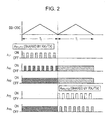
- one cycle of an operation by the radar apparatus 1 of this embodiment includes by a time slot [0,PT f ] and a time slot [PT f ,(P+Q)T f ] (where the measurement starting time is equal to 0). More specifically, in the time slot [0,PT f ], the antenna A R1/T1 operates as a shared antenna, and the antennas A R2 to A RN operate as reception antennas. In the time slot [PT f ,(P+Q)T f ], the antenna A RN/T2 operates as a shared antenna, and the antennas A R1 to A RN-1 operate as reception antennas.
- the LNA 12 is provided in a processing line corresponding to a reception antenna.
- an LNA 122 to an LNA 12N-1 are connected to the reception antennas A R2 to A RN-1 , respectively, at all times.
- the LNA 121 is connected to the reception antenna A R1 in response to the switching of the switch 191.
- the LNA 12N is connected to the reception antenna A RN in response to the switching of the switch 192.
- the LNA 12 receives a reception signal from a reception antenna connected thereto and amplifies the reception signal. The amplified signal is transmitted to the mixer 14.
- the mixer 14 is connected to the LNA 12.
- the mixer 14 mixes the signal amplified by the LNA 12 with the system reference signal transmitted from the oscillating module 17 to convert the high-frequency echo signal to a baseband signal.
- the system reference signal transmitted from the oscillating module 17 to convert the high-frequency echo signal to a baseband signal.
- FIG. 1 not all components such as a filter are explicitly illustrated.
- the A/D converter 15 converts the baseband signal output from the mixer 14 to a digital baseband signal with a predetermined sampling frequency, Hereinafter, the digital baseband signal will be simply called a demodulated signal.
- the demodulated signal is transmitted to the signal processing unit 20.
- FIG. 3 is a conceptual diagram illustrating a positional relationship between a detection target and a reception sensor array.
- the sensor array 11 forms a uniform linear array antenna having N reception antennas at equal element intervals d.
- Independent M detection target (TARGET in FIG. 3 ) is present at the position at a distance r m and angle ⁇ m from the coordinate origin.
- the angle ⁇ m is an angle defined when the positive direction of the Y-axis illustrated in FIG. 3 is set to 0 degree and the clockwise of FIG. 3 is set as the positive direction.
- FIG. 3 only illustrates one detection target, the maximum number M of detection targets detectable by the apparatus in FIG. 1 may be equal to or lower than [(2N-1)/2], for example, where [ ] is a gauss symbol when the targets are moving at an equal distance from the apparatus and at an equal speed (in the same speed direction).
- FIG. 3 illustrates that a baseband signal x m T1 (t) arrives at the sensor array 11 with an angle ⁇ m .
- the baseband signal x m T1 (t) is a signal possibly resulting from the demodulation processing in the processing units as described above on an echo signal (containing the positional information on the detection target) as a result of the reflection of a probe signal radiated from the antenna A R1/T1 to a detection area by the m-th detection target.
- the m is one integer of 1 to M
- t is a time.
- the baseband signal x m T1 (t) will be called a target echo signal.
- the demodulated signal v n T1 (t) corresponding to the probe signal radiated from the antenna A R1/T1 to the detection area, received by the n-th antenna A Rn and signal processed in the processing units may be expressed by Expression (1.1).
- the ⁇ n,m T1 expressed by Expression (1.2) indicates a spatial phase reflecting the angle of a detection target, that is, the reception phase of the m-th wave at the reception antenna A Rn
- the n n T1 (t) indicates the additive Gauss noise of power ⁇ 2 .
- the n is an integer of 1 to N (the number of physical reception antennas).
- v n T1 (t) expressed in Expression (1.1) will be called a synthesized echo signal.
- the demodulated signal v n T1 (t) is acquired at the time slot [0,T f ] illustrated in FIG. 2 .
- a synthesized echo signal v n T2 (t) expressed by Expression (1.3) below is acquired.
- the A RN/T2 is used as a shared antenna, and the A R1 to A RN-1 are used as reception antennas.
- Expression (1.3) is based on the following idea. That is, as described above, because the cycle of the reference signal is T f , the radar apparatus 1 operates at a basic frequency of 2 ⁇ /T f .
- the target echo signal corresponding to a probe signal radiated from the antenna A RN/T2 may be considered as x m T2 (t) ⁇ x m T1 (t + T f ). Furthermore, in consideration of the basic frequency, the target echo signal may be considered as x m T1 (t + T f ) ⁇ x m T1 (t).
- the spatial phase ⁇ n,m T2 is different from the spatial phase ⁇ n,m T1 since the positions of the transmission antennas being the reference points of spatial phases are different.
- the synthesized echo signals as described above are transmitted to the signal processing unit 20.
- the signal processing unit 20 performs aperture synthesis processing on the synthesized echo signals, and the positional information on the detection target is estimated on the basis of the aperture synthesized signal.
- the signal processing unit 20 will be described in detail below.
- FIG. 4 is a block diagram illustrating a configuration example of the signal processing unit 20.
- the signal processing unit 20 includes a signal synthesizing unit 21, a correction data acquiring unit 22, a correction processing unit 23, a covariance matrix calculating unit 24, a kernel matrix calculating unit 25, and a direction-of-arrival estimating unit 26. These units are implemented as software components, hardware components, or combinations thereof.
- the signal synthesizing unit 21 aperture synthesizes 2N synthesized echo signals acquired through one cycle of the operation in the radar apparatus 1 of this embodiment.
- the signal synthesizing unit 21 in this case performs an operation of unifying reference points of the phases of the synthesized echo signals.
- the signal of the reference points are selected from synthesized echo signals acquired by combinations of transmission antennas and reception antennas which may provide an equal spatial phase between two time slots.
- the reference points are the synthesized echo signal v 1 T1 (t) acquired from the antenna A R1 at the time slot [0,T f ] and the synthesized echo signal v N T2 (t) acquired from the antenna A RN at the time slot [T f ,2T f ] in the timing chart in FIG. 2 .
- the synthesized echo signals v 1 T1 (t) and v N T2 (t) have an equal spatial phase reference and are thus added. As a result, the number of elements of the aperture synthesized echo signal v is equal to (2N-1).
- the signal synthesizing unit 21 transmits the generated aperture synthesized echo signal to the correction processing unit 23.
- the correction data acquiring unit 22 acquires the correction data for correcting the aperture synthesized echo signal, and transmits the correction data to the correction processing unit 23.
- the correction data is acquired as a correction matrix C or correction vector c having the coefficient (f l ) of the synthesized equally-spaced array polynomial corresponding to an order of z (noted below).
- the coefficient f l is designed in advance with array polynomials such as Expressions (2.1a), (2.1b) and (2.1c) below on the basis of the parameters of the transmission antennas and reception antennas and is held as an adjustable value in a memory, for example.
- the parameters of the transmission antennas and reception antennas are designed such that the synthesized array polynomial f(z) of Expression (2.1c) below can exhibit a uniform linear array antenna with an element interval d and the number of elements L.
- the parameters may be the number of elements, element interval, gain characteristic, phase characteristic and/or the like relating to transmission antennas and reception antennas.
- the ⁇ k in the expressions above is a coefficient expressing the magnification ratio of the interval of transmission elements about the reference element interval d.
- the g k is a complex constant of the gain characteristic or phase characteristic of a transmission antenna or a combination of them.
- the subscript k indicates an identification number of each transmission antenna and is an integer of 1 to the number of transmission antennas (K). According to this embodiment, the subscript k is 1 or 2.
- the ⁇ n is a coefficient expressing the magnification ratio of the interval of reception elements about the reference element interval d.
- the h n is a complex constant of the gain characteristic or phase characteristic of a reception antenna or a combination of them.
- the subscript n indicates an identification number of each reception antenna and is an integer of 1 to the number of reception antennas (N). According to this embodiment, the subscript n is an integer of 1 to N.
- the L is the number of terms as a result of the organization of the orders of the synthesized array polynomial f(z).
- the correction data acquiring unit 22 uses it to acquire the correction matrix C or correction vector c.
- the correction matrix C is expressed by Expression (2.2a) below, and the correction vector c is expressed by Expression (2.2b) below.
- the correction data acquiring unit 22 transmits the acquired correction data (correction vector c or correction matrix C) to the correction processing unit 23.
- the correction processing unit 23 applies the correction data acquired from the correction data acquiring unit 22 to the aperture synthesized echo signal transmitted from the signal synthesizing unit 21 so that the aperture synthesized echo signal can be corrected. More specifically, as expressed in Expression (2.3a) below, the correction processing unit 23 multiplies the aperture synthesized echo signal v with the correction matrix C to correct the aperture synthesized echo signal (refer to Expression (2.3a)). The correction processing unit 23 may acquire an Hadamard product (element-wise product) of the aperture synthesized echo signal v and the correction vector c to correct the aperture synthesized echo signal (refer to Expression (2.3b)). Hereinafter, the signal corrected by the correction processing unit 23 will be called a corrected echo signal. The corrected echo signal is transmitted to the covariance matrix calculating unit 24.
- the covariance matrix calculating unit 24 calculates a covariance matrix of the corrected echo signal transmitted from the correction processing unit 23.
- the covariance matrix calculation method is not limited. Therefore, it will be described briefly.
- MUSIC Multiple Signal Classification
- a Forward Spatial Smoothing may be applied to the matrix acquired by the product of the corrected echo signal w and the Hermitian conjugate transposition w H to acquire a matrix R MUSIC FSS .
- a Backward Spatial Smoothing may be applied to the matrix acquired from the product of the signal vector (Jw*) acquired from the product of the anti-diagonal matrix J and a complex conjugate w* of the corrected echo signal w and Hermitian conjugate transposition (Jw*) H to acquire a matrix R MUSIC BSS .
- the covariance matrix calculating unit 24 acquires a matrix acquired by adding the matrix R MUSIC FSS and the matrix R MUSIC BSS and dividing the result by 2 as a covariance matrix R MUSIC FBSS .
- PRISM Propagator-method based on an Improved Spatial-smoothing Matrix
- a quasi-covariance matrix R PRISM having a generalized Hankel structure is acquired from the corrected echo signal w and a part of the elements.
- the matrix R PRISM has the same information as a normal covariance used in MUSIC method, for example, but has a different matrix structure. Thus, it will be called a quasi-covariance matrix herein for distinction.
- the kernel matrix calculating unit 25 calculates a matrix for angle estimation (hereinafter, called a kernel matrix) from the covariance matrix acquired by the covariance matrix calculating unit 24.
- the kernel matrix calculation method is not limited according to this embodiment and therefore will be described briefly.
- the covariance matrix R MUSIC FBSS undergoes eigenvalue decomposition so that matrix E N including an eigenvector representing a noise subspace and a matrix E S including an eigenvector representing a signal subspace can be acquired.
- the product of the matrix E N and the complex conjugate transposition (same as the Hermitian conjugate transposition) of the matrix E N can be acquired as a kernel matrix ⁇ MUSIC .
- submatrices R 1 and R 2 are acquired from the quasi-covariance matrix R PRISM (refer to Expression (2.4a) below), and the submatrices R 1 and R 2 are used to generate a linear operator r (refer to Expression (2.4b) below).
- the superscript H in Expression (2.4b) below denotes a complex conjugate transposition (same as the Hermitian conjugate transposition also noted above, and the annotation is omitted hereafter).
- the linear operator ⁇ and a unit matrix I (2N - 1) - 2M of the ((2N-1)-2M) order are used to generate a propagator matrix ⁇ , as expressed by Expression (2.4c) below.
- the M is [(2N - 2) / 2] by using the Gauss symbol [ ].
- the scaling matrix ⁇ is generated from the linear operator r and submatrix R 1 and R 2 , as expressed by Expression (2.4d) below.
- the kernel matrix calculating unit 25 uses the propagator matrix ⁇ and scaling matrix ⁇ to calculate the kernel matrix ⁇ PRISM by using Expression (2.4e).
- MUSIC method and PRISM method which can be used by the covariance matrix calculating unit 24 and kernel matrix calculating unit 25 are well-known methods, and other methods may be used instead.
- MUSIC method a reference document ( IEEE Trans. Antennas Propagation, Vol. 34, (Mar. 1986), pp. 276-280 ) is quoted.
- PRISM method the reference document ( IEEE Trans. Intelligent Transportation Systems, Vol. 9, No. 3, (Sept. 2008), pp. 451-461 ) or the reference document (International Publication Pamphlet No. WO2006/67869 , Japanese Patent Application No. 2006-548672 ) is quoted.
- the direction-of-arrival estimating unit 26 uses the kernel matrix calculated by the kernel matrix calculating unit 25 for angle estimation.
- the angle estimation method to be used by the direction-of-arrival estimating unit 26 is not limited.
- the angle estimation method may be a well-known technology.
- the kernel matrix calculated by the kernel matrix calculating unit 25 is used to calculate an angle spectrum (refer to Expression (2.5a) or Expression (2.5b) below).
- P MUSIC ⁇ a H ⁇ ⁇ a ⁇ a H ⁇ ⁇ ⁇ MUSIC a ⁇
- the direction-of-arrival estimating unit 26 may solve the algebraic equation defined by (Expression 2.6a) below using the kernel matrix ⁇ calculated by the kernel matrix calculating unit 25 for angle estimation.
- the matrix ⁇ is a matrix of the (S x S) order
- the vector a(z) of Expression (2.6a) can be defined by Expression (2.6c) below.
- Expression (2.6b) below is provided as the m-th solution. If the value
- is close to 1, the direction-of-arrival estimating unit 26 uses ⁇ m arcsin [( ⁇ (2 ⁇ d)) arg(z m )] as the estimated angle.
- the probe signals radiated from the transmission antenna A T1 and A T2 are reflected by M detection targets, and the echo signals are thus generated and arrived at the reception antennas A R1 to A RN .
- the LNA 12, mixer 14, A/D converter 15 and so on operate so that 2N synthesized echo signals are acquired from the echo signals in one cycle operation (time slots [0,T f ] and [T f ,2T f ] in the example in FIG. 2 ).
- the thus acquired 2N synthesized echo signals are aperture synthesized by the signal synthesizing unit 21 illustrated in FIG. 4 .
- the aperture synthesized echo signal resulting from the aperture synthesis can be expressed by Expression (1.5) above.
- the target echo signal vector x and noise signal vector n are defined as Expression (3.1) and Expression (3.2) below and the angle matrix A is defined by Expressions (3.3) and (3.4)
- the basic relationship expression of the array signal processing can be derived as in Expression (3.5) below regarding the aperture synthesized echo signal.
- the angle matrix A as expressed by Expression (3.3) is used to function the radar apparatus 1 of this embodiment as a radar apparatus having a uniform linear array antenna including (2N-1) reception antennas.
- Expression (3.3) above has some terms in which the element of the mode vector a( ⁇ ) is 2. This is proved from the appearance of 2 as the coefficient of the array polynomial after the aperture synthesis as expressed by Expression (4.3) below.
- the term in which the coefficient is 2 in the array polynomial f(z) after the aperture synthesis means that data measurement is performed twice in the N-th antenna of the uniform linear array after the aperture synthesis.
- the aperture synthesized echo signal acquired by the signal synthesizing unit 21 is corrected in the correction processing unit 23 with the correction data acquired by the correction data acquiring unit 22.
- the correction data is acquired as a correction matrix or correction vector which is set to cancel the coefficients (f l ) corresponding to the orders of the synthesized array polynomial being the uniform linear array.
- the aperture synthesized echo signal in which the coefficients corresponding to the orders of the synthesized array polynomial being the uniform linear array are cancelled is used to calculate a covariance matrix (by the covariance matrix calculating unit 24), and the kernel matrix is acquired from the covariance matrix (by the kernel matrix calculating unit 25).
- the direction-of-arrival estimating unit 26 performs angle estimation.
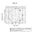
- FIG. 5 illustrates a positional relationship between zeros of a synthesized array polynomial in this embodiment and zeros of a mode vector on a Gaussian plane.
- FIG. 5 illustrates an example in which the number of transmission antennas is equal to 2, and the number of reception antennas N is equal to 4.
- zeros (black circles illustrated in FIG. 5 ) of a synthesized array polynomial is located equally spaced on the circumference. The zeros (gray circles illustrated in FIG.
- some radar apparatuses perform angle estimation without correction of aperture synthesized echo signals as in this embodiment by the correction data acquiring unit 22 and correction processing unit 23.
- this type of radar apparatus will be called a comparison radar apparatus, and angle estimation processing in the comparison radar apparatus will be described below.
- the comparison radar apparatus uses aperture synthesized echo signals which are not corrected as in Expression (5.1) below.
- MUSIC method is applied as an angle estimating algorithm
- the signal vector in Expression (5.1) is used to generate a covariance matrix R MUSIC as in Expression (5.2) below.
- a Forward Spatial Smoothing is applied to the covariance matrix R MUSIC to acquire the covariance matrix R MUSIC FSS as in Expression (5.3) below
- a covariance matrix is acquired for the product Jv* of the anti-diagonal matrix J and the complex conjugate of v.
- the matrix R MUSIC BSS is further acquired as a result of the application of a Backward Spatial Smoothing to the covariance matrix, and the matrix R MUSIC FBSS of Expression (5.4) below is acquired as the covariance matrix to be used for angle estimation.
- the thus acquired covariance matrix R MUSIC FBSS undergoes eigenvalue decomposition as expressed by Expression (5.4) below to acquire a matrix E N including an eigenvector representing a noise subspace and a matrix E S including an eigenvector representing a signal subspace.
- the product of the matrix E N and the complex conjugate transposition of the matrix E N is acquired as a kernel matrix ⁇ MUSIC (refer to Expression (5.5)).
- the kernel matrix ⁇ MUSIC is used for the angle estimation.
- the signal vector in Expression (5.1) is used to generate a quasi-covariance matrix R PRISM as in Expression (5.6) below.
- the quasi-covariance matrix R PRISM is used to generate the kernel matrix ⁇ PRISM with Expression (2.4b), Expression (2.4c), Expression (2.4d) and Expression (2.4e) above.
- the kernel matrix ⁇ PRISM is used for performing angle estimation.
- R PRISM v 2 ⁇ v 1 * 2 ⁇ v 3 ⁇ v 1 * v 1 ⁇ v 5 * v 2 ⁇ v 5 * v 5 ⁇ v 2 * v 5 ⁇ v 1 * 2 ⁇ v 1 ⁇ v 3 * v 1 ⁇ v 2 * 2 ⁇ v 3 ⁇ v 1 * v 4 ⁇ v 1 * v 2 ⁇ v 5 * 2 ⁇ v 3 ⁇ v 5 * 2 ⁇ v 5 ⁇ v 3 * v 5 ⁇ v 2 * v 1 ⁇ v 4 * 2 ⁇ v 1 ⁇ v 3 * v 4 ⁇ v 1 * v 5 ⁇ v 1 * 2 ⁇ v 3 ⁇ v 4 * 2 ⁇ v 1 ⁇ v 3 * v 4 ⁇ v 1 * v 5 ⁇ v 1 * 2 ⁇ v 3 ⁇ v 5 * v 4 ⁇ v 1 * v 5 ⁇ v
- a covariance matrix used in the comparison radar apparatus includes an element multiplied by a coefficient even when any one of angle estimating algorithms is applied. Multiplying an element of a covariance matrix by a coefficient may result in an eigenvalue, which is different from the actual (or ideal) eigenvalue, as a result of the eigenvalue decomposition on the matrix for example. Thus, the change in eigenvector may lower the precision of angle estimation.
- FIG. 6 illustrates a positional relationship between zeros of a synthesized array polynomial in a comparison radar apparatus and zeros of a mode vector on a Gaussian plane.
- FIG. 6 illustrates an example in which the number of transmission antennas is equal to 2 and the number of reception antennas N is equal to 4, like FIG. 5 .
- the array polynomial after the aperture synthesis in the comparison radar apparatus is described by Expression (4.3) being different from a cyclotomic polynomial, the zeros are not uniformly positioned unlike those shown in FIG. 5 , and a multiple root (black point with the number "2" in FIG. 6 ) is also appearing.
- FIG. 7 is a graph illustrating angle estimation precision.
- FIG. 7 illustrates the angle estimation precision by a comparison radar apparatus and by the radar apparatus 1 of this embodiment both including aperture synthesis array antennas where the number of transmission antennas K is equal to 2, the number of reception antennas N is equal to 4, and the reference antenna interval d is equal to 1.8 ⁇ .
- an FMCW signal is used which has a carrier frequency of 76 GHz, a one-side modulation band width of 50 MHz and a modulation cycle of 4 msec.
- Two detection targets T1 and T2 are set which have the target specifications (distance, speed and angle) below.
- the SNR is set to 20 dB.
- the angle spectrum level is colored about the Z-axis with respect to angle estimating algorithms on the plane formed by an angle (X-axis) and a distance (Y-axis).
- the graph under the title FFT-DBF illustrates a result of the application of Digital Beam Former ((DBF) using Fourier transform) method as an angle estimating algorithm in the comparison radar apparatus.
- the graph under the title mPRISM illustrates a result of the application of an improved PRISM method quoted by the reference document (Japanese Patent Application No. 2009-201624 ) as an angle estimating algorithm in the comparison radar apparatus.
- the graph under the title mPRISM+ illustrates a result of the application of an improved PRISM method quoted by the reference document (Japanese Patent Application No. 2009-201624 ) as an angle estimating algorithm in the radar apparatus 1 of this embodiment.
- the lower right graph illustrates levels of angle spectrums in a distance where detection targets exist in four situations including the three situations described above.
- the angle estimation in the comparison radar apparatus has an error of about two degrees in estimation precision while the angle estimation in the radar apparatus 1 in this embodiment is improved to an error of about one degree.
- the angle estimation in the radar apparatus 1 according to this embodiment has improved angle estimation precision compared with the angle estimation in the comparison radar apparatus.
- the angle estimation in the radar apparatus 1 according to this embodiment allows clear distinction between the two detection targets while the angle estimation in the comparison radar apparatus lacks the clarity.
- the improved angle spectrum dynamic range helps easy identification of detected targets using the radar apparatus 1 according to this embodiment, when compared with the comparison radar apparatus.
- the radar apparatus 1 of this embodiment corrects the aperture synthesized echo signal with the coefficients corresponding to the orders of the synthesized array polynomial being the uniform linear array for higher angle estimation precision and an improved dynamic range of an angle spectrum.
- the radar apparatus 1 of this embodiment allows more precise estimation of the angle and distance of a detection target.
- a coefficient f l which is held in advance in a memory, for example, as an adjustable value is used for correcting an aperture synthesized echo signal.
- the embodiment is not limited to the configuration, but the coefficient f l may be updated by the power levels of synthesized echo signals.
- FIG. 8 is a block diagram illustrating a configuration example of a radar apparatus according to a variation example.
- the radar apparatus according to this variation example further includes a power measuring unit 30 which measures the power levels of synthesized echo signals acquired from A/D converters 15 in addition to the configuration of the aforementioned embodiment.
- the power measuring unit 30 measures the power levels of synthesized echo signals and calculates the proportions of the power levels of synthesized echo signals to a total of values of the power levels of all synthesized echo signals.
- the power level measurement by the power measuring unit 30 only requires the application of a well-known technology such as Fourier transform and a square detector, and the description will be omitted
- the correction data acquiring unit 22 acquires the proportion values calculated by the power measuring unit 30 and multiplies the acquired proportion values by the coefficient f l of a term of a synthesized polynomial held in advance in a memory to determine the latest coefficient f l .
- the coefficient of the term corresponding to an aperture synthesized echo signal is multiplied by the proportion value corresponding to the aperture synthesized echo signal.
- the correction data acquiring unit 22 uses the thus determined latest coefficient f l to acquire a correction vector or correction matrix.
- Each of the hardware components here refers to a hardware circuit such as a field programmable gate array (FPGA), an application-specific integrated circuit (ASIC), a gate array, a combination of logic gates, a signal processing circuit, and an analog circuit.
- FPGA field programmable gate array
- ASIC application-specific integrated circuit
- Each of the software components here refers to a part (piece) which implements the aforementioned processes in software, and the concept does not limit the language, development environment and so on for implementing the software.
- the software components may be a task, a process, a thread, a driver, a firmware, a database, a table, a function, a procedure, a subroutine, a predetermined part of program code, a data structure, an array, a variable, and/or a parameter, for example.
- These software components may be implemented on one or a plurality of memories within a computer or may be implemented by the execution of data in one or a plurality of memories by one or a plurality of processors (such as a CPU (Central Processing Unit) and a DSP (Digital Signal Processor)),
- processors such as a CPU (Central Processing Unit) and a DSP (Digital Signal Processor)
- the aforementioned embodiments do not limit the method for implementing the aforementioned processing units or units.
- Each of the processing units or units may only be required to configure by a method which can be implemented by a common person skilled in the technical field as a hardware component or software component or the combination of them.
Landscapes
- Engineering & Computer Science (AREA)
- Remote Sensing (AREA)
- Radar, Positioning & Navigation (AREA)
- Physics & Mathematics (AREA)
- Computer Networks & Wireless Communication (AREA)
- General Physics & Mathematics (AREA)
- Electromagnetism (AREA)
- Radar Systems Or Details Thereof (AREA)
Claims (4)
- Radargerät, umfassend:eine Gruppenantenne (11), die eine Vielzahl von Antennenelementen (AR1 bis ARN, AT1, AT2) aufweist und mindestens eine Funktion einer Sendeantenne und einer Empfangsantenne aufweist, wobei die Sendeantenne bedienbar ist, um ein Tastsignal mit einer vorbestimmten Zeiteinstellung abzustrahlen, und die Empfangsantenne bedienbar ist, um ein Echosignal zu empfangen, das eine Reflexion des Tastsignals von einem Zielobjekt (TARGET) ist;einen Wandler (14), um das Echosignal in ein Basisbandsignal umzuwandeln;eine Einheit zum Synthetisieren von Signalen (21), die bedienbar ist, um einen synthetisierten Basisbandsignalvektor auf der Grundlage einer Apertursynthese des Basisbandsignals zu erzeugen, das aus einer Kombination der Antennenelemente erzeugt wird, die eine gleiche räumliche Phase ergeben;eine Einheit zum Erfassen von Korrekturdaten (22), die bedienbar ist, um Korrekturdaten auf der Grundlage von Koeffizienten von Termen eines synthetisierten Gruppenpolynoms zu erfassen, das aus dem Produkt eines Gruppenpolynoms der Sendeantenne und eines Gruppenpolynoms der Empfangsantenne erzielt wird;eine Korrekturverarbeitungseinheit (23), die bedienbar ist, um den synthetisierten Basisbandsignalvektor auf der Grundlage der Korrekturdaten zu korrigieren; undeine Schätzeinheit (26), die bedienbar ist, um eine Winkelschätzung auf der Grundlage des synthetisierten Basisbandsignalvektors auszuführen, der von der Korrekturverarbeitungseinheit (23) korrigiert wird.
- Radargerät nach Anspruch 1, wobei:die Korrekturdaten eine Korrekturmatrix oder ein Korrekturvektor sind, die bzw. der die Kehrwerte der Koeffizienten der Terme des synthetisierten Gruppenpolynoms umfassen; unddie Korrekturverarbeitungseinheit (23) bedienbar ist, um den synthetisierten Basisbandsignalvektor auf der Grundlage des Produkts des synthetisierten Basisbandsignalvektors und der Korrekturmatrix oder des Hadamard-Produkts des synthetisierten Basisbandsignalvektors und des Korrekturvektors zu korrigieren.
- Radargerät nach Anspruch 1 oder 2, ferner umfassend:eine Messeinheit (30), die bedienbar ist, um den Energiepegel des empfangenen Echosignals zu messen, wobei:die Einheit zum Erfassen von Korrekturdaten (22) bedienbar ist, um die Koeffizienten der Terme des synthetisierten Gruppenpolynoms auf der Grundlage des Energiepegels des Echosignals, das von der Messeinheit (30) gemessen wird, zu aktualisieren.
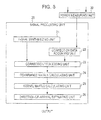
- Zielermittlungsverfahren, das von einem Gerät ausgeführt wird, das eine Gruppenantenne (11) umfasst, die eine Vielzahl von Antennenelementen (AR1 bis ARN, AT1, AT2) aufweist und mindestens eine Funktion einer Sendeantenne und einer Empfangsantenne aufweist, wobei das Verfahren folgende Schritte umfasst:Empfangen mit der Empfangsantenne eines Echosignals, das eine Reflexion eines Tastsignals von einem Zielobjekt ist, wobei das Tastsignal von der Sendeantenne zu einer vorbestimmten Zeiteinstellung abgestrahlt wird;Umwandeln des Echosignals in ein Basisbandsignal;Erzeugen eines synthetisierten Basisbandsignalvektors auf der Grundlage einer Apertursynthese des Basisbandsignals, das aus einer Kombination einer Sendeantenne und einer Empfangsantenne erzeugt wird, die eine gleiche räumliche Phase ergeben;Erfassen von Korrekturdaten auf der Grundlage von Koeffizienten der Terme eines synthetisierten Gruppenpolynoms, das aus dem Produkt eines Gruppenpolynoms der Sendeantenne und eines Gruppenpolynoms der Empfangsantenne erzielt wird;Korrigieren des synthetisierten Basisbandsignalvektors auf der Grundlage der Korrekturdaten; undAusführen einer Winkelschätzung auf der Grundlage des korrigierten synthetisierten Basisbandsignalvektors.
Applications Claiming Priority (1)
| Application Number | Priority Date | Filing Date | Title |
|---|---|---|---|
| JP2010108374A JP5617334B2 (ja) | 2010-05-10 | 2010-05-10 | レーダ装置及び目標探知方法 |
Publications (2)
| Publication Number | Publication Date |
|---|---|
| EP2386871A1 EP2386871A1 (de) | 2011-11-16 |
| EP2386871B1 true EP2386871B1 (de) | 2014-11-12 |
Family
ID=44280918
Family Applications (1)
| Application Number | Title | Priority Date | Filing Date |
|---|---|---|---|
| EP11164914.1A Not-in-force EP2386871B1 (de) | 2010-05-10 | 2011-05-05 | Radarvorrichtung |
Country Status (3)
| Country | Link |
|---|---|
| US (1) | US8816898B2 (de) |
| EP (1) | EP2386871B1 (de) |
| JP (1) | JP5617334B2 (de) |
Families Citing this family (19)
| Publication number | Priority date | Publication date | Assignee | Title |
|---|---|---|---|---|
| US8121821B1 (en) * | 2007-12-19 | 2012-02-21 | The United States Of America As Represented By The Secretary Of The Navy | Quasi-static design approach for low Q factor electrically small antennas |
| KR20120071851A (ko) * | 2010-12-23 | 2012-07-03 | 한국전자통신연구원 | 통신 시스템에서 신호 도래 방향 추정 장치 및 방법 |
| JP5628732B2 (ja) * | 2011-04-04 | 2014-11-19 | 富士通テン株式会社 | レーダ装置用の演算装置、レーダ装置、レーダ装置用の演算方法およびプログラム |
| US10228443B2 (en) * | 2012-12-02 | 2019-03-12 | Khalifa University of Science and Technology | Method and system for measuring direction of arrival of wireless signal using circular array displacement |
| KR101797792B1 (ko) * | 2013-07-05 | 2017-11-14 | 주식회사 만도 | 주파수 변조 연속파 레이더 감지 장치 및 그의 연속파를 이용한 물체 감지 방법 |
| TWI470257B (zh) * | 2013-10-07 | 2015-01-21 | Univ Nat Chiao Tung | 角度估計檢測方法及電子裝置 |
| CN106537181B (zh) * | 2014-04-03 | 2019-12-03 | 伊沃夫科技有限公司 | 用于雷达的特征提取 |
| US9651661B2 (en) * | 2014-04-09 | 2017-05-16 | Src, Inc. | Methods and systems for local principal axis rotation angle transform |
| DE112014006707B4 (de) | 2014-05-29 | 2021-07-29 | Toyota Jidosha Kabushiki Kaisha | Array-antennenvorrichtung |
| EP2963442B1 (de) * | 2014-07-04 | 2016-11-30 | Denso Corporation | Radarvorrichtung |
| US9791552B1 (en) * | 2014-11-19 | 2017-10-17 | Src, Inc. | On-site calibration of array antenna systems |
| US10359511B2 (en) | 2014-12-29 | 2019-07-23 | Sony Corporation | Surveillance apparatus having a radar sensor |
| CN104833947B (zh) * | 2015-04-03 | 2017-10-31 | 西北大学 | 一种任意阵接收对称虚拟变换2d‑doa分离算法 |
| DE112015007124T5 (de) * | 2015-12-11 | 2018-07-26 | GM Global Technology Operations LLC | Codieren einer Apertur zum Strahlformen beim Senden und Empfangen |
| JP6821091B2 (ja) * | 2018-05-07 | 2021-01-27 | 三菱電機株式会社 | 到来波数推定装置及び到来波数到来方向推定装置 |
| JP7152193B2 (ja) * | 2018-06-07 | 2022-10-12 | 株式会社デンソーテン | レーダ装置 |
| CN110531354B (zh) * | 2019-10-14 | 2021-07-20 | 上海无线电设备研究所 | 一种频控扫描雷达色散信号的二维成像方法 |
| CN111257883A (zh) * | 2020-02-13 | 2020-06-09 | 航天新气象科技有限公司 | 一种相控阵天气雷达系统的标校装置及方法 |
| KR102173012B1 (ko) * | 2020-08-26 | 2020-11-02 | 국방과학연구소 | 압축 센싱 기반 합성 개구면 레이다의 영상 생성 장치, 방법, 컴퓨터 판독 가능한 기록 매체 및 컴퓨터 프로그램 |
Family Cites Families (12)
| Publication number | Priority date | Publication date | Assignee | Title |
|---|---|---|---|---|
| US7109911B1 (en) * | 2002-04-01 | 2006-09-19 | Cataldo Thomas J | Dual synthetic aperture radar system |
| US7714782B2 (en) * | 2004-01-13 | 2010-05-11 | Dennis Willard Davis | Phase arrays exploiting geometry phase and methods of creating such arrays |
| US20050195103A1 (en) * | 2004-01-13 | 2005-09-08 | Davis Dennis W. | Phased arrays exploiting geometry phase and methods of creating such arrays |
| JP4833534B2 (ja) * | 2004-09-29 | 2011-12-07 | 富士通株式会社 | レーダ装置 |
| WO2006067857A1 (ja) * | 2004-12-24 | 2006-06-29 | Fujitsu Limited | 到来方向推定装置及びプログラム |
| JP2009080024A (ja) | 2007-09-26 | 2009-04-16 | Fujitsu Ltd | 探知測距装置および探知測距方法 |
| JP2009201624A (ja) | 2008-02-27 | 2009-09-10 | Olympia:Kk | 遊技機及び遊技機用プログラム及び記録媒体 |
| JP2010071653A (ja) * | 2008-09-16 | 2010-04-02 | Japan Radio Co Ltd | 距離測定装置 |
| JP5317602B2 (ja) * | 2008-09-19 | 2013-10-16 | 株式会社東芝 | 移動体搭載レーダ装置及びキャリブレーション方法 |
| US9110167B2 (en) * | 2008-10-07 | 2015-08-18 | The Boeing Company | Correction of spatially variant phase error for synthetic aperture radar |
| US7999724B2 (en) * | 2008-12-15 | 2011-08-16 | The Boeing Company | Estimation and correction of error in synthetic aperture radar |
| JP5470836B2 (ja) | 2008-12-19 | 2014-04-16 | 富士通株式会社 | 探知測距装置および探知測距装置の設計方法 |
-
2010
- 2010-05-10 JP JP2010108374A patent/JP5617334B2/ja not_active Expired - Fee Related
-
2011
- 2011-04-27 US US13/095,535 patent/US8816898B2/en not_active Expired - Fee Related
- 2011-05-05 EP EP11164914.1A patent/EP2386871B1/de not_active Not-in-force
Also Published As
| Publication number | Publication date |
|---|---|
| US20110273326A1 (en) | 2011-11-10 |
| EP2386871A1 (de) | 2011-11-16 |
| JP2011237257A (ja) | 2011-11-24 |
| JP5617334B2 (ja) | 2014-11-05 |
| US8816898B2 (en) | 2014-08-26 |
Similar Documents
| Publication | Publication Date | Title |
|---|---|---|
| EP2386871B1 (de) | Radarvorrichtung | |
| USRE49619E1 (en) | Radar device | |
| EP3309577B1 (de) | Radarvorrichtung | |
| US9618616B2 (en) | Radar apparatus | |
| CN110018452B (zh) | 使用虚拟接收信号的生成来估计到达方向的方法和设备 | |
| EP2293094B1 (de) | Verfahren zur Schätzung der Richtung des Empfangs und Vorrichtung dafür | |
| US20200251832A1 (en) | Radar device | |
| US10365349B2 (en) | Radar device | |
| US9507018B2 (en) | Detection and ranging apparatus and ranging method | |
| JP5865689B2 (ja) | 探知測距装置および角度推定方法 | |
| US9234956B2 (en) | Radar device | |
| US7782249B2 (en) | Detection and ranging device and detection and ranging method | |
| US7567201B2 (en) | Vehicle-installation direction detection apparatus enabling accurate detection of target body directions irrespective of vehicle speed | |
| US11275172B2 (en) | Target detection device | |
| EP3324205B1 (de) | Dezentralisiertes radarsystem | |
| US12146978B2 (en) | Radar device and transmitting/receiving array antenna | |
| US20190187266A1 (en) | Object detection apparatus and object detection method | |
| EP2508911B1 (de) | Berechnungsvorrichtung für Radarvorrichtungen, Berechnungsverfahren und Programm für Berechnungsverfahren | |
| JP6980979B2 (ja) | レーダ装置および物標検知方法 | |
| JP7413850B2 (ja) | 物体位置の角度推定装置及び方法、並びにレーダ装置 | |
| Scherhäufl et al. | Viterbi-Based Trajectory Estimation with Widely Spaced Receiving Radar Antennas | |
| Lukin et al. | Noise waveform sar imaging in antenna near zone |
Legal Events
| Date | Code | Title | Description |
|---|---|---|---|
| AK | Designated contracting states |
Kind code of ref document: A1 Designated state(s): AL AT BE BG CH CY CZ DE DK EE ES FI FR GB GR HR HU IE IS IT LI LT LU LV MC MK MT NL NO PL PT RO RS SE SI SK SM TR |
|
| AX | Request for extension of the european patent |
Extension state: BA ME |
|
| PUAI | Public reference made under article 153(3) epc to a published international application that has entered the european phase |
Free format text: ORIGINAL CODE: 0009012 |
|
| 17P | Request for examination filed |
Effective date: 20120515 |
|
| GRAP | Despatch of communication of intention to grant a patent |
Free format text: ORIGINAL CODE: EPIDOSNIGR1 |
|
| INTG | Intention to grant announced |
Effective date: 20140423 |
|
| GRAS | Grant fee paid |
Free format text: ORIGINAL CODE: EPIDOSNIGR3 |
|
| GRAA | (expected) grant |
Free format text: ORIGINAL CODE: 0009210 |
|
| AK | Designated contracting states |
Kind code of ref document: B1 Designated state(s): AL AT BE BG CH CY CZ DE DK EE ES FI FR GB GR HR HU IE IS IT LI LT LU LV MC MK MT NL NO PL PT RO RS SE SI SK SM TR |
|
| REG | Reference to a national code |
Ref country code: GB Ref legal event code: FG4D |
|
| REG | Reference to a national code |
Ref country code: CH Ref legal event code: EP |
|
| REG | Reference to a national code |
Ref country code: AT Ref legal event code: REF Ref document number: 696071 Country of ref document: AT Kind code of ref document: T Effective date: 20141115 |
|
| REG | Reference to a national code |
Ref country code: IE Ref legal event code: FG4D |
|
| REG | Reference to a national code |
Ref country code: DE Ref legal event code: R096 Ref document number: 602011011232 Country of ref document: DE Effective date: 20141224 |
|
| REG | Reference to a national code |
Ref country code: NL Ref legal event code: VDEP Effective date: 20141112 |
|
| REG | Reference to a national code |
Ref country code: AT Ref legal event code: MK05 Ref document number: 696071 Country of ref document: AT Kind code of ref document: T Effective date: 20141112 |
|
| PG25 | Lapsed in a contracting state [announced via postgrant information from national office to epo] |
Ref country code: PT Free format text: LAPSE BECAUSE OF FAILURE TO SUBMIT A TRANSLATION OF THE DESCRIPTION OR TO PAY THE FEE WITHIN THE PRESCRIBED TIME-LIMIT Effective date: 20150312 Ref country code: NO Free format text: LAPSE BECAUSE OF FAILURE TO SUBMIT A TRANSLATION OF THE DESCRIPTION OR TO PAY THE FEE WITHIN THE PRESCRIBED TIME-LIMIT Effective date: 20150212 Ref country code: LT Free format text: LAPSE BECAUSE OF FAILURE TO SUBMIT A TRANSLATION OF THE DESCRIPTION OR TO PAY THE FEE WITHIN THE PRESCRIBED TIME-LIMIT Effective date: 20141112 Ref country code: IS Free format text: LAPSE BECAUSE OF FAILURE TO SUBMIT A TRANSLATION OF THE DESCRIPTION OR TO PAY THE FEE WITHIN THE PRESCRIBED TIME-LIMIT Effective date: 20150312 Ref country code: FI Free format text: LAPSE BECAUSE OF FAILURE TO SUBMIT A TRANSLATION OF THE DESCRIPTION OR TO PAY THE FEE WITHIN THE PRESCRIBED TIME-LIMIT Effective date: 20141112 Ref country code: ES Free format text: LAPSE BECAUSE OF FAILURE TO SUBMIT A TRANSLATION OF THE DESCRIPTION OR TO PAY THE FEE WITHIN THE PRESCRIBED TIME-LIMIT Effective date: 20141112 Ref country code: NL Free format text: LAPSE BECAUSE OF FAILURE TO SUBMIT A TRANSLATION OF THE DESCRIPTION OR TO PAY THE FEE WITHIN THE PRESCRIBED TIME-LIMIT Effective date: 20141112 |
|
| PG25 | Lapsed in a contracting state [announced via postgrant information from national office to epo] |
Ref country code: CY Free format text: LAPSE BECAUSE OF FAILURE TO SUBMIT A TRANSLATION OF THE DESCRIPTION OR TO PAY THE FEE WITHIN THE PRESCRIBED TIME-LIMIT Effective date: 20141112 Ref country code: HR Free format text: LAPSE BECAUSE OF FAILURE TO SUBMIT A TRANSLATION OF THE DESCRIPTION OR TO PAY THE FEE WITHIN THE PRESCRIBED TIME-LIMIT Effective date: 20141112 Ref country code: AT Free format text: LAPSE BECAUSE OF FAILURE TO SUBMIT A TRANSLATION OF THE DESCRIPTION OR TO PAY THE FEE WITHIN THE PRESCRIBED TIME-LIMIT Effective date: 20141112 Ref country code: PL Free format text: LAPSE BECAUSE OF FAILURE TO SUBMIT A TRANSLATION OF THE DESCRIPTION OR TO PAY THE FEE WITHIN THE PRESCRIBED TIME-LIMIT Effective date: 20141112 Ref country code: RS Free format text: LAPSE BECAUSE OF FAILURE TO SUBMIT A TRANSLATION OF THE DESCRIPTION OR TO PAY THE FEE WITHIN THE PRESCRIBED TIME-LIMIT Effective date: 20141112 Ref country code: LV Free format text: LAPSE BECAUSE OF FAILURE TO SUBMIT A TRANSLATION OF THE DESCRIPTION OR TO PAY THE FEE WITHIN THE PRESCRIBED TIME-LIMIT Effective date: 20141112 Ref country code: GR Free format text: LAPSE BECAUSE OF FAILURE TO SUBMIT A TRANSLATION OF THE DESCRIPTION OR TO PAY THE FEE WITHIN THE PRESCRIBED TIME-LIMIT Effective date: 20150213 Ref country code: SE Free format text: LAPSE BECAUSE OF FAILURE TO SUBMIT A TRANSLATION OF THE DESCRIPTION OR TO PAY THE FEE WITHIN THE PRESCRIBED TIME-LIMIT Effective date: 20141112 |
|
| PG25 | Lapsed in a contracting state [announced via postgrant information from national office to epo] |
Ref country code: CZ Free format text: LAPSE BECAUSE OF FAILURE TO SUBMIT A TRANSLATION OF THE DESCRIPTION OR TO PAY THE FEE WITHIN THE PRESCRIBED TIME-LIMIT Effective date: 20141112 Ref country code: RO Free format text: LAPSE BECAUSE OF FAILURE TO SUBMIT A TRANSLATION OF THE DESCRIPTION OR TO PAY THE FEE WITHIN THE PRESCRIBED TIME-LIMIT Effective date: 20141112 Ref country code: DK Free format text: LAPSE BECAUSE OF FAILURE TO SUBMIT A TRANSLATION OF THE DESCRIPTION OR TO PAY THE FEE WITHIN THE PRESCRIBED TIME-LIMIT Effective date: 20141112 Ref country code: EE Free format text: LAPSE BECAUSE OF FAILURE TO SUBMIT A TRANSLATION OF THE DESCRIPTION OR TO PAY THE FEE WITHIN THE PRESCRIBED TIME-LIMIT Effective date: 20141112 Ref country code: SK Free format text: LAPSE BECAUSE OF FAILURE TO SUBMIT A TRANSLATION OF THE DESCRIPTION OR TO PAY THE FEE WITHIN THE PRESCRIBED TIME-LIMIT Effective date: 20141112 |
|
| REG | Reference to a national code |
Ref country code: DE Ref legal event code: R097 Ref document number: 602011011232 Country of ref document: DE |
|
| PLBE | No opposition filed within time limit |
Free format text: ORIGINAL CODE: 0009261 |
|
| STAA | Information on the status of an ep patent application or granted ep patent |
Free format text: STATUS: NO OPPOSITION FILED WITHIN TIME LIMIT |
|
| 26N | No opposition filed |
Effective date: 20150813 |
|
| PG25 | Lapsed in a contracting state [announced via postgrant information from national office to epo] |
Ref country code: IT Free format text: LAPSE BECAUSE OF FAILURE TO SUBMIT A TRANSLATION OF THE DESCRIPTION OR TO PAY THE FEE WITHIN THE PRESCRIBED TIME-LIMIT Effective date: 20141112 |
|
| REG | Reference to a national code |
Ref country code: CH Ref legal event code: PL |
|
| PG25 | Lapsed in a contracting state [announced via postgrant information from national office to epo] |
Ref country code: CH Free format text: LAPSE BECAUSE OF NON-PAYMENT OF DUE FEES Effective date: 20150531 Ref country code: LI Free format text: LAPSE BECAUSE OF NON-PAYMENT OF DUE FEES Effective date: 20150531 Ref country code: MC Free format text: LAPSE BECAUSE OF FAILURE TO SUBMIT A TRANSLATION OF THE DESCRIPTION OR TO PAY THE FEE WITHIN THE PRESCRIBED TIME-LIMIT Effective date: 20141112 Ref country code: LU Free format text: LAPSE BECAUSE OF FAILURE TO SUBMIT A TRANSLATION OF THE DESCRIPTION OR TO PAY THE FEE WITHIN THE PRESCRIBED TIME-LIMIT Effective date: 20150505 |
|
| REG | Reference to a national code |
Ref country code: IE Ref legal event code: MM4A |
|
| PG25 | Lapsed in a contracting state [announced via postgrant information from national office to epo] |
Ref country code: SI Free format text: LAPSE BECAUSE OF FAILURE TO SUBMIT A TRANSLATION OF THE DESCRIPTION OR TO PAY THE FEE WITHIN THE PRESCRIBED TIME-LIMIT Effective date: 20141112 |
|
| REG | Reference to a national code |
Ref country code: FR Ref legal event code: PLFP Year of fee payment: 6 |
|
| PG25 | Lapsed in a contracting state [announced via postgrant information from national office to epo] |
Ref country code: IE Free format text: LAPSE BECAUSE OF NON-PAYMENT OF DUE FEES Effective date: 20150505 |
|
| PG25 | Lapsed in a contracting state [announced via postgrant information from national office to epo] |
Ref country code: MT Free format text: LAPSE BECAUSE OF FAILURE TO SUBMIT A TRANSLATION OF THE DESCRIPTION OR TO PAY THE FEE WITHIN THE PRESCRIBED TIME-LIMIT Effective date: 20141112 |
|
| REG | Reference to a national code |
Ref country code: FR Ref legal event code: PLFP Year of fee payment: 7 |
|
| PG25 | Lapsed in a contracting state [announced via postgrant information from national office to epo] |
Ref country code: HU Free format text: LAPSE BECAUSE OF FAILURE TO SUBMIT A TRANSLATION OF THE DESCRIPTION OR TO PAY THE FEE WITHIN THE PRESCRIBED TIME-LIMIT; INVALID AB INITIO Effective date: 20110505 Ref country code: SM Free format text: LAPSE BECAUSE OF FAILURE TO SUBMIT A TRANSLATION OF THE DESCRIPTION OR TO PAY THE FEE WITHIN THE PRESCRIBED TIME-LIMIT Effective date: 20141112 Ref country code: BG Free format text: LAPSE BECAUSE OF FAILURE TO SUBMIT A TRANSLATION OF THE DESCRIPTION OR TO PAY THE FEE WITHIN THE PRESCRIBED TIME-LIMIT Effective date: 20141112 |
|
| PGFP | Annual fee paid to national office [announced via postgrant information from national office to epo] |
Ref country code: FR Payment date: 20170413 Year of fee payment: 7 Ref country code: DE Payment date: 20170502 Year of fee payment: 7 Ref country code: GB Payment date: 20170503 Year of fee payment: 7 |
|
| PG25 | Lapsed in a contracting state [announced via postgrant information from national office to epo] |
Ref country code: TR Free format text: LAPSE BECAUSE OF FAILURE TO SUBMIT A TRANSLATION OF THE DESCRIPTION OR TO PAY THE FEE WITHIN THE PRESCRIBED TIME-LIMIT Effective date: 20141112 |
|
| PG25 | Lapsed in a contracting state [announced via postgrant information from national office to epo] |
Ref country code: BE Free format text: LAPSE BECAUSE OF FAILURE TO SUBMIT A TRANSLATION OF THE DESCRIPTION OR TO PAY THE FEE WITHIN THE PRESCRIBED TIME-LIMIT Effective date: 20141112 |
|
| PG25 | Lapsed in a contracting state [announced via postgrant information from national office to epo] |
Ref country code: MK Free format text: LAPSE BECAUSE OF FAILURE TO SUBMIT A TRANSLATION OF THE DESCRIPTION OR TO PAY THE FEE WITHIN THE PRESCRIBED TIME-LIMIT Effective date: 20141112 |
|
| PG25 | Lapsed in a contracting state [announced via postgrant information from national office to epo] |
Ref country code: AL Free format text: LAPSE BECAUSE OF FAILURE TO SUBMIT A TRANSLATION OF THE DESCRIPTION OR TO PAY THE FEE WITHIN THE PRESCRIBED TIME-LIMIT Effective date: 20141112 |
|
| REG | Reference to a national code |
Ref country code: DE Ref legal event code: R119 Ref document number: 602011011232 Country of ref document: DE |
|
| GBPC | Gb: european patent ceased through non-payment of renewal fee |
Effective date: 20180505 |
|
| PG25 | Lapsed in a contracting state [announced via postgrant information from national office to epo] |
Ref country code: FR Free format text: LAPSE BECAUSE OF NON-PAYMENT OF DUE FEES Effective date: 20180531 Ref country code: GB Free format text: LAPSE BECAUSE OF NON-PAYMENT OF DUE FEES Effective date: 20180505 Ref country code: DE Free format text: LAPSE BECAUSE OF NON-PAYMENT OF DUE FEES Effective date: 20181201 |