EP2963442B1 - Radarvorrichtung - Google Patents
Radarvorrichtung Download PDFInfo
- Publication number
- EP2963442B1 EP2963442B1 EP14175851.6A EP14175851A EP2963442B1 EP 2963442 B1 EP2963442 B1 EP 2963442B1 EP 14175851 A EP14175851 A EP 14175851A EP 2963442 B1 EP2963442 B1 EP 2963442B1
- Authority
- EP
- European Patent Office
- Prior art keywords
- elements
- receiver elements
- receiver
- virtual
- transmitter
- Prior art date
- Legal status (The legal status is an assumption and is not a legal conclusion. Google has not performed a legal analysis and makes no representation as to the accuracy of the status listed.)
- Active
Links
- 238000000034 method Methods 0.000 claims description 31
- 238000003491 array Methods 0.000 claims description 20
- 239000011159 matrix material Substances 0.000 claims description 19
- 238000012935 Averaging Methods 0.000 claims description 8
- 238000009499 grossing Methods 0.000 claims description 7
- 238000012545 processing Methods 0.000 description 16
- 230000008901 benefit Effects 0.000 description 14
- 230000005540 biological transmission Effects 0.000 description 14
- 230000000875 corresponding effect Effects 0.000 description 11
- 238000010276 construction Methods 0.000 description 6
- 230000002596 correlated effect Effects 0.000 description 6
- 238000006073 displacement reaction Methods 0.000 description 5
- 230000004048 modification Effects 0.000 description 4
- 238000012986 modification Methods 0.000 description 4
- 230000009471 action Effects 0.000 description 3
- 238000000354 decomposition reaction Methods 0.000 description 3
- 230000004044 response Effects 0.000 description 3
- 230000003044 adaptive effect Effects 0.000 description 2
- 230000035559 beat frequency Effects 0.000 description 2
- 230000001427 coherent effect Effects 0.000 description 2
- 238000010586 diagram Methods 0.000 description 2
- 230000000694 effects Effects 0.000 description 2
- 230000006872 improvement Effects 0.000 description 2
- 238000002955 isolation Methods 0.000 description 2
- 230000008569 process Effects 0.000 description 2
- 238000000926 separation method Methods 0.000 description 2
- 241000282326 Felis catus Species 0.000 description 1
- 230000006978 adaptation Effects 0.000 description 1
- 238000004458 analytical method Methods 0.000 description 1
- 230000015572 biosynthetic process Effects 0.000 description 1
- 238000004364 calculation method Methods 0.000 description 1
- 238000001514 detection method Methods 0.000 description 1
- 238000011161 development Methods 0.000 description 1
- 238000005562 fading Methods 0.000 description 1
- 230000010355 oscillation Effects 0.000 description 1
- 238000007781 pre-processing Methods 0.000 description 1
- 230000000644 propagated effect Effects 0.000 description 1
- 230000005855 radiation Effects 0.000 description 1
Images


Classifications
-
- G—PHYSICS
- G01—MEASURING; TESTING
- G01S—RADIO DIRECTION-FINDING; RADIO NAVIGATION; DETERMINING DISTANCE OR VELOCITY BY USE OF RADIO WAVES; LOCATING OR PRESENCE-DETECTING BY USE OF THE REFLECTION OR RERADIATION OF RADIO WAVES; ANALOGOUS ARRANGEMENTS USING OTHER WAVES
- G01S13/00—Systems using the reflection or reradiation of radio waves, e.g. radar systems; Analogous systems using reflection or reradiation of waves whose nature or wavelength is irrelevant or unspecified
- G01S13/02—Systems using reflection of radio waves, e.g. primary radar systems; Analogous systems
- G01S13/06—Systems determining position data of a target
- G01S13/42—Simultaneous measurement of distance and other co-ordinates
- G01S13/44—Monopulse radar, i.e. simultaneous lobing
- G01S13/4454—Monopulse radar, i.e. simultaneous lobing phase comparisons monopulse, i.e. comparing the echo signals received by an interferometric antenna arrangement
-
- G—PHYSICS
- G01—MEASURING; TESTING
- G01S—RADIO DIRECTION-FINDING; RADIO NAVIGATION; DETERMINING DISTANCE OR VELOCITY BY USE OF RADIO WAVES; LOCATING OR PRESENCE-DETECTING BY USE OF THE REFLECTION OR RERADIATION OF RADIO WAVES; ANALOGOUS ARRANGEMENTS USING OTHER WAVES
- G01S13/00—Systems using the reflection or reradiation of radio waves, e.g. radar systems; Analogous systems using reflection or reradiation of waves whose nature or wavelength is irrelevant or unspecified
- G01S13/02—Systems using reflection of radio waves, e.g. primary radar systems; Analogous systems
- G01S13/06—Systems determining position data of a target
- G01S13/08—Systems for measuring distance only
- G01S13/32—Systems for measuring distance only using transmission of continuous waves, whether amplitude-, frequency-, or phase-modulated, or unmodulated
- G01S13/34—Systems for measuring distance only using transmission of continuous waves, whether amplitude-, frequency-, or phase-modulated, or unmodulated using transmission of continuous, frequency-modulated waves while heterodyning the received signal, or a signal derived therefrom, with a locally-generated signal related to the contemporaneously transmitted signal
-
- G—PHYSICS
- G01—MEASURING; TESTING
- G01S—RADIO DIRECTION-FINDING; RADIO NAVIGATION; DETERMINING DISTANCE OR VELOCITY BY USE OF RADIO WAVES; LOCATING OR PRESENCE-DETECTING BY USE OF THE REFLECTION OR RERADIATION OF RADIO WAVES; ANALOGOUS ARRANGEMENTS USING OTHER WAVES
- G01S13/00—Systems using the reflection or reradiation of radio waves, e.g. radar systems; Analogous systems using reflection or reradiation of waves whose nature or wavelength is irrelevant or unspecified
- G01S13/02—Systems using reflection of radio waves, e.g. primary radar systems; Analogous systems
- G01S13/06—Systems determining position data of a target
- G01S13/42—Simultaneous measurement of distance and other co-ordinates
-
- G—PHYSICS
- G01—MEASURING; TESTING
- G01S—RADIO DIRECTION-FINDING; RADIO NAVIGATION; DETERMINING DISTANCE OR VELOCITY BY USE OF RADIO WAVES; LOCATING OR PRESENCE-DETECTING BY USE OF THE REFLECTION OR RERADIATION OF RADIO WAVES; ANALOGOUS ARRANGEMENTS USING OTHER WAVES
- G01S13/00—Systems using the reflection or reradiation of radio waves, e.g. radar systems; Analogous systems using reflection or reradiation of waves whose nature or wavelength is irrelevant or unspecified
- G01S13/88—Radar or analogous systems specially adapted for specific applications
- G01S13/93—Radar or analogous systems specially adapted for specific applications for anti-collision purposes
- G01S13/931—Radar or analogous systems specially adapted for specific applications for anti-collision purposes of land vehicles
-
- G—PHYSICS
- G01—MEASURING; TESTING
- G01S—RADIO DIRECTION-FINDING; RADIO NAVIGATION; DETERMINING DISTANCE OR VELOCITY BY USE OF RADIO WAVES; LOCATING OR PRESENCE-DETECTING BY USE OF THE REFLECTION OR RERADIATION OF RADIO WAVES; ANALOGOUS ARRANGEMENTS USING OTHER WAVES
- G01S7/00—Details of systems according to groups G01S13/00, G01S15/00, G01S17/00
- G01S7/02—Details of systems according to groups G01S13/00, G01S15/00, G01S17/00 of systems according to group G01S13/00
- G01S7/28—Details of pulse systems
- G01S7/285—Receivers
- G01S7/292—Extracting wanted echo-signals
- G01S7/2921—Extracting wanted echo-signals based on data belonging to one radar period
-
- G—PHYSICS
- G01—MEASURING; TESTING
- G01S—RADIO DIRECTION-FINDING; RADIO NAVIGATION; DETERMINING DISTANCE OR VELOCITY BY USE OF RADIO WAVES; LOCATING OR PRESENCE-DETECTING BY USE OF THE REFLECTION OR RERADIATION OF RADIO WAVES; ANALOGOUS ARRANGEMENTS USING OTHER WAVES
- G01S7/00—Details of systems according to groups G01S13/00, G01S15/00, G01S17/00
- G01S7/02—Details of systems according to groups G01S13/00, G01S15/00, G01S17/00 of systems according to group G01S13/00
- G01S7/35—Details of non-pulse systems
- G01S7/352—Receivers
- G01S7/354—Extracting wanted echo-signals
-
- G—PHYSICS
- G01—MEASURING; TESTING
- G01S—RADIO DIRECTION-FINDING; RADIO NAVIGATION; DETERMINING DISTANCE OR VELOCITY BY USE OF RADIO WAVES; LOCATING OR PRESENCE-DETECTING BY USE OF THE REFLECTION OR RERADIATION OF RADIO WAVES; ANALOGOUS ARRANGEMENTS USING OTHER WAVES
- G01S13/00—Systems using the reflection or reradiation of radio waves, e.g. radar systems; Analogous systems using reflection or reradiation of waves whose nature or wavelength is irrelevant or unspecified
- G01S13/88—Radar or analogous systems specially adapted for specific applications
- G01S13/93—Radar or analogous systems specially adapted for specific applications for anti-collision purposes
- G01S13/931—Radar or analogous systems specially adapted for specific applications for anti-collision purposes of land vehicles
- G01S2013/93185—Controlling the brakes
-
- G—PHYSICS
- G01—MEASURING; TESTING
- G01S—RADIO DIRECTION-FINDING; RADIO NAVIGATION; DETERMINING DISTANCE OR VELOCITY BY USE OF RADIO WAVES; LOCATING OR PRESENCE-DETECTING BY USE OF THE REFLECTION OR RERADIATION OF RADIO WAVES; ANALOGOUS ARRANGEMENTS USING OTHER WAVES
- G01S3/00—Direction-finders for determining the direction from which infrasonic, sonic, ultrasonic, or electromagnetic waves, or particle emission, not having a directional significance, are being received
- G01S3/02—Direction-finders for determining the direction from which infrasonic, sonic, ultrasonic, or electromagnetic waves, or particle emission, not having a directional significance, are being received using radio waves
- G01S3/74—Multi-channel systems specially adapted for direction-finding, i.e. having a single antenna system capable of giving simultaneous indications of the directions of different signals
Definitions
- the invention relates to a radar apparatus for carrying out two-dimensional direction of arrival (2D DOA) estimation, preferably for use with an automatic emergency braking system of a vehicle (AEBS).
- 2D DOA two-dimensional direction of arrival
- AEBS automatic emergency braking system of a vehicle
- Fig. 1 shows a geometry for estimating the vertical bearing of an object using the automotive radar.
- Fig. 1 shows a vehicle 10 located on a road surface 7.
- the forward direction of the vehicle 10 is defined by the direction of arrow A.
- the vehicle 10 is provided with a forward looking radar apparatus 12A having a transmitting antenna and a receiving antenna arranged at a distance H2, which is a mounting height, above the ground.
- An object 3 which is a target to be detected by the radar apparatus 12A is positioned ahead of the vehicle 10 at a distance H3 above the ground, which is greater than the height H10 of the vehicle 10.
- the object may be a road sign board, for example.
- the function of the radar apparatus 12A according to prior art for detecting the vertical bearing of the object 3 is described as follows. Radar waves emitted by the transmitting antenna are subsequently reflected off the object 3 and propagate towards the receiving antenna of the radar apparatus 12A. The vertical bearing of the object 3 is estimated by detecting the angle of incidence of the arriving wave by means of the phase monopulse method.
- the radar waves arrive at the receiving antenna of the radar apparatus 12A via at least two different signal paths.
- the first signal path 5 is a direct path from the object 3 to the receiving antenna.
- the second signal path 6, which is a multipath signal, is an additional signal path that is reflected from the road surface 7 before arriving at the receiving antenna.
- the road surface 7 acts as a mirror and so there will be more than one signal from the object 3. If the difference in path lengths is shorter than the radar's range resolution, the received signal will be a superposition of signals that propagated the two signal paths 5 and 6. Attempting to estimate the height of the object 3 by means of the phase mono-pulse method will result in an incorrect height estimate.
- phase mono-pulse method cannot distinguish between the object and its "ghost" 4 which is the signal from the object which is reflected off the road surface 7. Only one object within a range distance cell can be detected via the mono-pulse method. Since the superpositioned signals are correlated and unresolved, the vertical bearing of the detected bearing is estimated as a fluctuating value in-between the true target height and the virtual height of the reflected signal. This fluctuating value may cause unnecessary control in such an automatic emergency braking system (AEBS).
- AEBS automatic emergency braking system
- EP 0 947 852 A1 provides a radar apparatus that detects a vertical bearing of an object in addition to a horizontal bearing of an object.
- the radar apparatus has a transmitting antenna comprising a transmitting element and a receiving antenna comprising an array of receiver elements and wherein one or more receiver elements is shifted with respect to the remaining receiver elements by the same vertical displacement. This vertical shift is used to detect a vertical bearing of the target object by using the phase mono-pulse method.
- EP 0987561 A2 discloses a radar device wherein two receiver elements are aligned with three transmitter elements which are switched on in sequence. The receiver elements are alternately connected to a signal processing means in dependence of the switching of the transmitter elements. Therefore the radar device according to EP 0987561 A2 is able to acquire signals equivalent to ones obtained in radars having a single transmission antenna and six reception antennas, and to reduce the number of the reception antennas.
- US 2011/0057831 A1 discloses a radar device including a transmission antenna group having a plurality of transmission antennas; a reception antenna group having a plurality of reception antennas; and transmission switchover means to transmit transmission waves in a way that sequentially switches over the transmission antennas of the transmission antenna group, the reception antenna group receiving reflected waves, reflected from a target, of transmission waves of the transmission antennas when sequentially transmitting the transmission waves, is made to function as a virtual sub-array corresponding to the transmission antennas, and the target is detected by executing a space averaging process.
- the object underlying the present invention is to estimate the vertical bearing of an elevated object in an improved manner by means of a radar apparatus having a reduced size and simple construction.
- a radar apparatus (12) comprises: transmitting means (16) including a plurality of transmitter elements (30) for emitting a transmitting signal as a radar wave toward an object (3); receiving means (20) including a plurality of receiver elements (34) for receiving a reflection signal which is a reflection of the transmitting signal by the object (3); means (56) for generating a virtual receiving array (38) consisting of virtual receiver elements whose number corresponds to the number of receiver elements (34) multiplied by the number of transmitting elements (30); means (56) for dividing the virtual receiving array (38) into a plurality of identical sub-arrays (42, 44, 46, 48); means for generating covariance matrix data for each of the sub-arrays based on the reflection signal; means (56) for spatially smoothing the reflection signal by means of averaging the covariance matrix data for each of the sub-arrays to decorrelate the direct
- reflection signals are able to be subsequently processed to create a virtual receiving array of receiver elements.
- the number of the virtual receiver elements in the virtual receiving array corresponds to the number of receiver elements multiplied by the number of transmitter elements.
- the virtual array of receiver elements is divided into identical sub-arrays which facilitates further signal processing of the reflection signals.
- covariance matrix data for each of the sub-arrays are generated based on the reflection signal.
- the covariance matrix data are spatially smoothed by means of averaging to decorrelate the direct reflection signal from the object and multipath reflection signal among the reflection signal. As a result, the direct reflection signal from the object and multipath reflection signal are resolved. Therefore, it is possible to estimate the directions of arrival of a plurality of objects with higher resolution.
- a second aspect of the invention preferably according to the first aspect, comprises an antenna layout for a radar apparatus, comprising the transmitting means comprising at least two transmitter elements, and the receiving means comprising at least three receiver elements which are arranged in at least two rows in a first direction and at least three columns in a second direction perpendicular to the first direction, wherein the respective distance in said first direction between neighboring ones of all of said at least two transmitter elements corresponds to the respective distance in said first direction between neighboring ones of all receiver elements in neighboring rows multiplied by the number of rows of receiver elements.
- the vertical extent of the virtual array is greater than the vertical extent of the real receiving antenna. Therefore resolution in the vertical direction is improved.
- the virtual receiving array is generated that comprises more receiver elements than the real receiver array alone and the effective aperture size of the receiver antenna is increased. Therefore the size and complexity of the radar apparatus is reduced.
- the vertical extent of the each receiver element in the virtual array is not limited by neighbouring receiver elements.
- a third aspect of the invention comprises an antenna layout according to the second aspect wherein, in the case of an odd number of receiver elements, the transmitter elements are provided in the same column.
- an antenna layout according to the third aspect it is possible to create a virtual array of receiver elements using an odd number of real receiver elements wherein the virtual array has a regular structure. This makes further signal processing of the received signals easier.
- a fourth aspect of the invention comprises an antenna layout according to the second aspect wherein, in the case of an even number of receiver elements, the respective distance in said second direction between neighboring ones of all of said at least two transmitter elements in neighboring rows corresponds to the respective distance in said second direction between neighboring receiver elements in different rows multiplied by the number of rows of receiver elements.
- a fifth aspect of the invention comprises a radar apparatus according to the second aspect wherein, in the virtual receiving array, the number of virtual receiver elements is doubled in the first direction in comparison to the number of receiver elements in the receiver antenna in the first direction.
- the sixth aspect of the invention has the further advantage that the number of virtual receiver elements in the virtual array is increased further which increases further the aperture size of the receiver antenna.
- the transmitting means includes at least two transmitter elements and the receiving means includes at least two groups of receiver elements wherein each group has at least two receiver elements which are arranged in at least two rows in a first direction and at least two columns in a second direction perpendicular to the first direction, wherein the respective distance in said second direction between neighboring ones of all of said at least two transmitter elements in the same row corresponds to the twofold of the respective distance in said second direction between neighboring ones of all receiver elements in one group, and wherein the respective distance in the second direction in the same row between structurally corresponding receiver elements of neighboring groups of receiver elements corresponds to the respective distance in the second direction between neighboring ones of all of said at least two transmitter elements in the same row multiplied by the number of transmitter elements in one row.
- the number of receiver elements per group per row is one.
- the real receiver elements do not overlap. Therefore the vertical extent of each real receiver element is not limited. Furthermore due to the spacing between groups of real receiver elements, the average separation between receiver elements is larger and isolation of the receiver elements is increased. Furthermore it is possible to subsequently create a virtual receiving array of receiver elements wherein the number of virtual receiver elements in the virtual array is greater than the number of real receiver elements and the radar apparatus is kept small and of simple construction.
- a seventh aspect of the invention comprises a radar apparatus according to the sixth aspect, wherein, in the virtual receiving array, the number of virtual receiver elements is doubled in the second direction in comparison to the number of receiver elements in the receiver antenna in the second direction
- the seventh aspect of the invention has the further advantage that the number of virtual receiver elements in the virtual array is increased further which improves the resolution performance of the radar apparatus.
- An eighth aspect of the invention comprises a radar apparatus according to one of the first to seventh aspects, wherein the transmitter elements and the receiver elements are disposed in the same plane and the first direction is a vertical direction and a second direction is horizontal direction.
- the eighth aspect of the invention has the advantage that a simple construction of the receiver and transmitter antennas is ensured and the signal processing is facilitated.
- a ninth aspect of the invention comprises a radar apparatus according to one of the first to eight aspects additionally comprising means for applying an eigenstructure technique to each of the covariance matrix data of the virtual receiving array for estimating the direction of arrival of signals.
- the ninth aspect of the invention has the advantage that the directions of arrival of a plurality of objects can be detected by the radar apparatus with high resolution.
- a tenth aspect of the invention provides a radar apparatus according to the thirteenth aspect, wherein the eigenstructure technique is the multiple signal classification (MUSIC) algorithm.
- MUSIC multiple signal classification
- the tenth aspect of the invention has the advantage that the resolution of direction of arrival estimation is further increased.
- Fig. 1 shows a vehicle 10 located on a road surface 7.
- the forward direction of the vehicle 1 is defined by the direction of arrow A.
- the vehicle 10 is provided with a forward looking radar apparatus 12.
- One or more objects which are targets to be detected by the radar apparatus 12 are positioned ahead of the vehicle 10.
- Fig. 1 only one of these objects is shown wherein the object 3 is positioned ahead of the vehicle 10 at a distance H3 above the ground which is greater than the height H10 of the vehicle 10.
- distance H3 may be equal to or smaller than height H10 so as to form a potential obstacle in the vehicle's path.
- the object 3 may be a road sign board, for example.
- the radar apparatus 12 is capable of emitting radar waves and measuring the waves which return to the radar apparatus 12 after reflecting off the object 3.
- the radar apparatus 12 receives not only the direct reflection signal (shown as signal path 5) but also the multipath reflection signal which is reflected off the road surface 7 (shown as signal path 6).
- Fig. 2 shows a schematic view of the radar apparatus 12 according to, preferably all, embodiments.
- the radar apparatus 12 is configured as a so-called "millimeter-wave radar” based on an FMCW (Frequency-Modulated Continuous Wave) system.
- the radar apparatus 12 transmits and receives frequency-modulated electromagnetic waves in a millimeter-wave band as radar waves to and from the object.
- the radar apparatus 12 generates information regarding the object and transmits the information to AEBS 14.
- a D/A (digital to analog) converter 27 generates triangle-shape modulation signal in response to a modulation command from a signal processing means 26.
- a signal generator 28 changes an oscillation frequency thereof in response to the modulation signal generated by the D/A converter 27.
- a distributor 13 distributes the output signal of the signal generator 28 into a transmission signal sent to a switching means 32 and a local signal sent to a mixer 21.
- the switching means 32 selects one of the transmitter elements 30 such that only one transmitter element 30 is transmitting the radar wave and each transmitter element 30 transmits radar waves for a certain period based on the transmission signal.
- the transmitting antenna 16 emits the radar waves in response to the transmission signal.
- the radar apparatus 12 includes a receiving antenna 20, the mixer 21, an amplifier 23 and an A/D converter 25.
- the receiving antenna 20 receives radar waves which are the reflection of the radar waves emitted from the transmitting antenna 16.
- the mixer 21 mixes the received signal from the receiving antenna 20 with the local signal thereby generating the beat signal.
- the amplifier 23 amplifies the beat signal generated by the mixer 21.
- the A/D converter 25 samples the beat signal amplified by the amplifier 23 and converts the sampled signal into the digital data.
- the beat signal is a frequency component of the difference between the received signal and the local signal. It is noted that the frequency component of the beat signal is called the beat frequencies. The frequencies are used for calculation the range and the velocity between the own vehicle and the object by FMCW method.
- each signal generator 28 feeds respectively differing signals to each transmitter element 30 so that the transmitter elements 30 transmit respectively differing radar waves simultaneously.
- the radar apparatus 12 in particular the receiving antenna 20 and preferably also the transmitting antenna 16, is arranged at a distance H2 above the ground, as shown in Fig. 1 .
- the signals received by the receiving antenna 20 subsequently pass to a signal processing means 26 provided in the radar apparatus 12.
- Said signal processing means 26 is capable of processing the measured signals received by the receiving antenna 20 and, in combination with information regarding the signals emitted by the transmitting antenna 16, determining the range, velocity and 2D DOA of the object 3.
- the output of the signal processing means 26 is subsequently reported via an object reporting means 60, which is capable of removing ghost object signals from the output of the signal processing means 26, to the AEBS 14 provided in the vehicle.
- the AEBS 14 is able to make a decision on whether a collision with the object 3 is imminent and, based on this decision, inform the driver of any imminent collision and/or apply the brakes of the vehicle so that any collision is avoided or mitigated. Therefore the AEBS 14 is able to determine whether a collision is imminent based on the range, velocity and 2D DOA of the object 3 measured by the radar apparatus 12 in combination with the mounting height H2 of the receiving antenna 20 and preferably also the transmitting antenna 16, and the height H10 of the vehicle.
- the transmitting antenna 16 comprises n transmitter elements 30 of the same radiation pattern which are capable of emitting radar waves independently of each other either simultaneously or sequentially.
- the transmitter elements 30 are named T1 to Tn in Fig. 2 . Only transmitter elements T1 and Tn are shown in Fig. 2 . The relative positioning of the transmitter elements 30 is described in a later section.
- the receiving antenna 20 comprises m receiver elements 34 which are capable of receiving radar waves, wherein m is at least three.
- the receiver elements 34 are named R1 to Rm. Only receiver elements R1 and Rm are shown in Fig. 2 . The relative positioning of the receiver elements 34 is described in a later section.
- the signal processing means 26 is fed with signals which correspond to the radar waves emitted by each transmitter element 30, and with signals which correspond to the radar waves received by the receiver elements 34.
- the functional units within the signal processing means 26 according, preferably all, embodiments are described in detail in the following.
- the signal processing means 26 has a range and velocity calculating means 52 for determining the range and velocity of the object 3.
- the radar waves transmitted by a single transmitting antenna 30 and detected by the receiving elements 34 are processed by the range and velocity calculating means 52.
- the range and velocity calculating means 52 calculates the range and velocity of the object 3 based on the beat frequencies using methods known to the skilled person.
- the output of the range and velocity calculating means 52 is processed by a detecting means 54 which can determine on the basis of the output of the range and velocity calculating means 52 whether one or more objects is present in front of the vehicle 10.
- the output of the detector 54 is fed to a 2D DOA estimating means 56.
- Estimation of the vertical and horizontal bearing of the object 3 is performed here according to methods described in a later section.
- the 2D DOA estimating means 56 uses the data passed from the output of the detecting means 54 and combines it with the corresponding 2D DOA values for each object. The processing is performed over a plurality of successive time periods.
- the 2D DOA estimating means 56 produces an estimate of the vertical and horizontal bearing of an object or objects for every time period t.
- the output of the 2D DOA estimating means 56 which comprises data regarding the range, velocity, and horizontal and vertical bearings of any object or objects detected by the 2D DOA estimating means 56 at regular time intervals, is fed to a tracking means 58.
- the tracking means 58 analyses this data over a plurality of time periods and estimates the condition of the object whether or not the object has changed position relative to the vehicle 10 in a successive time period by using a Kalmar Filter for example.
- the tracking means 56 is capable of sending object data which is data concerning the range, velocity and 2D DOA of each detected object.
- the object data sent by the tracking means 58 is subsequently sent to the Automatic Emergency Braking System (AEBS) 14 via an object reporting means 60 which is capable of determining, from within the object data provided by the tracking means 58, ghost objects which are signals from objects which are reflected off the road surface 7.
- the determining is performed on the basis of the vertical bearing of each detected object and the mounting height H2 of the receiving antenna 20 and preferably also the transmitting antenna 16, preferably additionally on the basis of whether the detected object is positioned above or below the road surface 7.
- the object reporting means 60 is capable of determining ghost objects additionally on the basis of other object data, such as range and velocity of each detected object, and/or sensor data from other sensors within the vehicle, such as a GPS system or a sensor or sensors capable of detecting road gradient, for example.
- the object reporting means 60 is capable of subsequently removing these ghost objects from the object data before sending it from the radar apparatus 12 to the AEBS 14.
- the object reporting means 60 is not limited to sending data to the AEBS 14 only.
- the object reporting means 60 may also be capable of sending data from the radar apparatus 12 to other functional units within the vehicle 10 such an adaptive cruise control system (not shown) that is capable of adjusting the vehicle speed to maintain a safe distance from the vehicles ahead.
- the object reporting means 60 is capable of sending data concerning only real objects to other functional units.
- Data regarding objects arriving at the AEBS 14 from the object reporting means 60 passes first to an imminent-collision predicting means 62.
- Said data comprises the number of objects and the range, velocity and 2D DOA of each object.
- the imminent-collision predicting means 62 calculates the vertical and horizontal position of each object 3 relative to the vehicle 10 based on this data, the mounting height H2 of the receiving antenna 20 and preferably also the transmitting antenna 16, and the height H10 of the vehicle.
- the imminent-collision predicting means 62 is capable of determining the imminence of a collision with the object on the basis of the horizontal and vertical position of the object 3 relative to the vehicle 10, and the object's range and velocity.
- the imminent-collision predicting means 62 sends an imminent-collision predicting signal to be received by the driver warning requesting means 64.
- the imminent-collision predicting means 62 is capable to stop sending the imminent-collision predicting signal when it is determined that a collision with the object 3 is no longer imminent.
- the driver warning requesting means 64 is capable of determining whether to activate a driver warning signal based on a signal from the imminent-collision predicting means 62. When it is determined to activate the warning signal, the driver warning requesting means 64 sends a driver warning requesting signal to a driver warning means 66 which can be an acoustic alarm and/or a light on the dashboard, for example. In addition the driver warning requesting means 64 sends the driver warning request signal to the brake requesting means 70. The driver warning requesting means 64 is capable of stopping sending the driver warning requesting signal to both the driver warning means 66 and the brake requesting means 70 when the imminent-collision predicting signal is stopped.
- the brake requesting means 70 is capable of determining whether to apply the brakes based on the driver warning request signal from the driver warning requesting means 64 in combination with whether the driver has not taken evasive action within a predetermined time period since the driver warning means 66 was activated. Parameters such as the speed of the vehicle may optionally be used here. Evasive action may comprise braking or steering around the object 3, for example.
- the brake requesting means 70 is capable of stopping sending of the brake request when the driver warning request signal is stopped.
- the brake requesting means 70 sends a brake request signal to a braking means 72 which is capable of automatically applying the brakes of the vehicle 10 without action of the driver.
- Fig. 3 shows an antenna layout 11 according to the first embodiment of the invention, comprising the transmitting antenna 16 and the receiving antenna 20 described above and shown in Fig. 2 .
- the squares marked T1 and T2 each represent the phase centre of a respective transmitter element 30 and the squares marked R1 to R8 each represent the phase centre of a respective receiver element 34.
- Each transmitter element 30 and receiver element 34 may comprise a plurality of patch antennas connected together.
- the receiver elements 34 and transmitter elements 30 are disposed in the same plane.
- the eight receiver elements R1 to R8 are arranged in a W-shape comprising two rows of receiver elements 34 wherein the rows are relatively shifted by a horizontal shift dh such that the vertical extent of each receiver element 34 does not overlap a receiver element 34 arranged above or below the first.
- the receiving antenna 20 comprises 8 receiver elements 34 arranged in 8 equispaced columns and 2 rows with 4 receiving elements 34 per row.
- the rows of receiver elements 34 are spaced apart vertically by a distance Hr.
- the two transmitter elements 30 are displaced relatively to each other in a vertical direction by a distance Ht and in a horizontal direction by a distance Wt.
- the signal processing means 26 is able to generate, based on signals transmitted by the transmitter elements 30 and received by the receiver elements 34, a virtual array 38 of virtual receiver elements 40, which is shown in Fig. 4 .
- the signals emitted by a given transmitter element 30 and received by the receiver elements R1 to R8 are identical to those received if the same transmitter element 30 is displaced and the receiver elements 34 are displaced by a corresponding distance but in the opposite direction.
- the transmitting array 16 with two transmitter elements T1,T2 may be considered as a transmitting array with one transmitter element T1
- the receiving antenna 20 may be considered as a virtual receiving array 38 with sixteen receiving elements Rv1 to Rv16.
- the positions of the virtual receiver elements Rv9 to Rv16 are determined by translating the positions of the virtual receiver elements Rv1 to Rv8 respectively by a displacement corresponding to the displacement of the transmitter element T2 with respect to the transmitter element T1.
- the virtual array 38 comprises 16 virtual receiver elements Rv1 to Rv16 arranged on four rows, each comprising four receiver elements 34 wherein neighboring rows are relatively shifted horizontally by a distance corresponding to the horizontal shift dh between neighboring rows of receiver elements 34 in the real receiver antenna 20.
- the rows are spaced vertically by a distance Hr.
- the number of effective receiver elements has been doubled.
- the present invention is not limited to a receiving array 20 comprising eight receiver elements 34.
- the arrangement of transmitter elements 30 does not need to be modified in this case.
- the embodiments described in later sections comprise further possible transmitting element 30 and receiving element 34 arrangements.
- the distance Wt between the two transmitter elements 30 in the horizontal direction preferably corresponds to twice the horizontal shift dh between neighboring rows of receiver elements 34.
- the distance Wr between two neighboring receiver elements R1 and R3 in the same row preferably corresponds to the distance Wt.
- the vertical distance Ht between the two transmitter elements 30 corresponds to twice the vertical distance Hr between neighboring rows of receiver elements 34.
- the 2D DOA estimating means 56 is capable of estimating the horizontal and vertical bearings of objects using the output of each receiver element 40 in the virtual array.
- the direction-of-arrival estimation algorithms that may be used here are so-called eigenvalue techniques based on the eigenvalue decomposition of the sample covariance matrix of the vector of received signals.
- sample covariance is abbreviated to "covariance”.
- DOA is estimated from the covariance matrix.
- the covariance matrix of the virtual antenna 38 in Fig. 4 is a (16 x 16) matrix.
- Eigenvalue decomposition algorithms known from prior art may be used here, such as ESPRIT and Capon.
- the preferred algorithm is the MUSIC (Multiple Signal Classification) algorithm which is described, for example, by R. O. Schmidt in “Multiple Emitter Location and Signal Parameter Estimation,” (IEEE Trans., vol. AP-34, No.3, pp.276-280, March 1986 ).
- An advantage of the MUSIC method is increased resolution of DOA estimation especially in the presence of noise.
- the performance of the radar apparatus 12 that estimates 2D DOA by means of an eigenstructure technique can be improved especially in the case of decorrelating coherent or highly correlated signals.
- Examples of such signals could be two other vehicles driving side-by-side, or a direct signal from a road sign board and the signal from its mirror image reflected off the road, for example.
- the radar apparatus 12 it is advantageous for the radar apparatus 12 to be capable of decorrelating signals.
- Two methods for improving decorrelation are given in the following, wherein either one or both of the improvement methods are used in addition to the eigenvalue techniques mentioned above.
- the 2D DOA estimating means 56 is capable of dividing all the virtual receiver elements 40 in the virtual receiving array 38 into overlapping identical sub-arrays each comprising a portion of the total number of virtual receiver elements 40 in the virtual array 38 and a covariance matrix for each sub-array is determined.
- the sub-arrays 42, 44, 46 and 48 are shown in Fig.
- sub-array 42 comprises virtual receiver elements Rv1, Rv3, Rv5, Rv2, Rv4, Rv6, Rv9, Rv11 and Rv13
- sub-array 44 comprises Rv2, Rv4, Rv6, Rv9, Rv11, Rv13, Rv10, Rv12 and Rv14
- sub-array 46 comprises Rv3, Rv5, Rv7, Rv4, Rv6, Rv8, Rv11, Rv13 and Rv15
- sub-array 48 comprises Rv4, Rv6, Rv8, Rv11, Rv13, Rv15, Rv12, Rv14 and Rv16. Therefore each sub-array comprises nine virtual receiver elements 40 and so the covariance matrix for each sub-array is a (9 x 9) matrix.
- the 2D DOA estimating means 56 is capable of subsequently calculating an average covariance matrix which is a mean average of the covariance matrices of the sub-arrays and has size (9 x 9).
- the receiver elements 34 of the receiving antenna 20, specifically their phase centers, are arranged such that the virtual receiver elements 40 of the virtual array 38 can be divided into overlapping sub-arrays of identical geometry.
- the effect of the averaging of the sub-array covariance matrices is to decorrelate the two signals, since the sub-arrays receive signals from the objects from slightly different positions, and so the number of snapshots is increased by a factor of four.
- the phase difference between the direct signal and the multipath signal will vary between the sub-arrays and this will lead to a decorrelation.
- the forward-backward averaging method exploits the symmetrical structure of the virtual array 38 and the phase centers of its sub-arrays 42, 44, 46 and 48 shown in Fig. 4a . For every sub-array with phase center at a position relative to the center of the virtual array 38 represented by a vector p, there is also a phase center a position represented by vector -p. Forward-backward averaging is then applied to the covariance matrix so that it is arranged into a Toeplitz structure. Therefore signals are decorrelated further.
- any of the eigenvalue techniques mentioned above, preferably the MUSIC algorithm, are then performed on the modified covariance matrix that results from either or both of the above improvement methods. Therefore signals such as a direct signal from an object and the ghost signal from its reflection in the road surface 7 can be decorrelated and resolved.
- the problem of multipath reflections becomes more severe as the mounting height of the radar apparatus is increased. A reason is that more energy needs to be directed downward by the transmitting antenna 16 in order to observe low objects. Another reason is that the angle difference between the direction to the true object 3 and the direction to the reflected object 4 becomes smaller. Therefore when detecting low objects in front of the vehicle 10 it should be borne in mind that despite the methods applied in the present invention there is still some possibility of false detection of highly correlated signals.
- the method can be further improved by considering mounting height, for example as mounting height increases it is advantageous to increase the number of receiver element rows in the virtual array.
- the signal processing means 26 may process the signals from the transmitter elements 30 and receiver elements 34 such that a virtual array 38 of virtual receiver elements 40 is generated.
- the number of virtual receivers 40 is twice the number of real receivers 34.
- the virtual array 38 comprises an arrangement of virtual receiver elements 40 that is impossible to construct from receiver elements 34, especially when considering the limitations of vertical dimensions of an antenna layout for a car. Referring to the virtual array 38 shown in Fig. 4 , this is because virtual receiver elements Rv3 to Rv14 are arranged in a column above or below another virtual receiver element 40. For example virtual receiver element Rv9 is arranged in a column with and below virtual receiver element Rv3. If these virtual receiver elements 40 were part of a real array of receiver elements, the vertical extent of these receiver elements would have to be reduced to prevent overlapping. On the other hand overlapping by virtual receiver elements is possible in the virtual array 38. No overlapping with neighboring receiver elements occurs between receiver elements 34 in the receiving antenna 20. Therefore the vertical extent of each receiver element in both the real receiver antenna 20 and the virtual array 38 can be increased.
- the virtual array 38 comprises more than two rows of virtual receiver elements 40 with more than two virtual receiver elements 40 per row.
- a covariance matrix of signals from the virtual array 38 can be constructed and 2D DOA of objects can be estimated using eigenvalue techniques.
- the horizontal and vertical bearings of more than one object can be simultaneously determined.
- the present embodiment provides advantages over radar apparatuses according to prior art that use the phase monopulse method to detect the vertical bearing of an object. In this case the vertical bearing of only one object can be determined at any one time.
- respective signals from multiple objects can be resolved and objects above the road are not detected as being straight ahead. It is also possible to reduce the size of the receiving antenna 20 compared to a configuration in which a real receiver antenna comprises the same number of receiver elements as the virtual array 38 of the present embodiment.
- the arrangement of virtual receivers 40 in the virtual array 38 has a symmetrical geometry and can be divided into identical and overlapping sub-arrays. This allows the spatial smoothing techniques described above to be used to decorrelate correlated signals such as a direct signal from an object and the signal from its reflection in the road surface 7. After decorrelation the two signals can be resolved.
- the radar apparatus 12 is capable of providing the AEBS 14 with accurate information regarding the vertical bearing of objects.
- the object reporting means 60 is capable of determining that the reflected signals are not sources of real objects, and false intervention based on these signals, such as sending a driver warning request or sending a brake request, is avoided.
- Fig. 5 shows an antenna layout 111 according to the second embodiment of the invention, comprising a transmitting antenna 116 and receiving antenna 120.
- the receiving antenna 120 comprises four receiver elements R1 to R4 relatively arranged in the same positions as receiver elements R1 to R4 of the first embodiment of Fig. 3 .
- the transmitting antenna 116 comprises two transmitter elements T1 and T2 arranged in the same positions as the transmitter elements T1 and T2 of the first embodiment of Fig. 3 .
- the two transmitter elements T1, T2 are displaced relatively to each other in a vertical direction by a distance Ht which corresponds to twice Hr, and in a horizontal direction by a distance Wt which corresponds to twice dh.
- the distance Wr preferably corresponds to the distance Wt.
- Fig. 6 shows the virtual array 138 of virtual receiver elements 40 according to the second embodiment of the invention.
- the virtual array 138 comprises eight virtual receiver elements Rv1 to Rv8 arranged on four rows, each row comprising two virtual receiver elements, wherein neighboring rows are relatively shifted horizontally by a distance corresponding to the horizontal shift dh between neighboring rows of receiver elements 34.
- the receiving antenna 120 according to the second embodiment of the invention comprises four receiver elements R1 to R4, which is four fewer elements than for the receiver antenna 20 according to the first embodiment. In this way a simpler receiver antenna construction is possible.
- the virtual array 138 of virtual receiver elements Rv1 to Rv8 can be divided into identical sub-arrays wherein for example the first sub-array comprises virtual receiver elements Rv1 to Rv4, Rv5 and Rv7 and the second sub-array comprises virtual receiver elements Rv2 to Rv7, Rv6 and Rv8. In this way 2D DOA via spatial smoothing is possible.
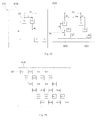
- Fig. 7 shows an antenna layout 211 according to the third embodiment of the invention, comprising a transmitting antenna 216 and a receiving antenna 220.
- the receiving antenna 220 comprises three receiver elements R1 to R3 relatively arranged in the same positions as receiver elements R1 to R3 of the receiving antenna 20 of the first embodiment of Fig. 3 .
- the receiving antenna 220 comprises three receiver elements 34 arranged in three equispaced columns and two rows wherein the spacing between columns in the horizontal direction is dh.
- the rows of receiver elements 34 are spaced apart vertically by a distance Hr.
- the rows comprise two and one receiver elements 34 respectively.
- the transmitting antenna 216 comprises two transmitter elements T1 and T2 arranged in a column.
- the two transmitter elements T1, T2 are displaced relatively to each other in a vertical direction by a distance Ht which corresponds to twice Hr.
- Fig. 8 shows the virtual array 238 of virtual receiver elements 40 according to the third embodiment of the invention.
- the virtual array 238 comprises six receivers Rv1 to Rv6 arranged on four rows, each row comprising alternately two or one virtual receiver elements, Because the distance Ht in the vertical direction between transmitter elements 30 corresponds to twice the distance Hr in the horizontal direction between receiver elements 34, neighboring rows of virtual receiver elements 40 are equispaced.
- the antenna layout 211 according to the third embodiment of the invention requires fewer receiver elements 34 than for the first embodiment of the invention.
- the horizontal spacing of the transmitter elements 30 is zero. Therefore a simple construction of the radar apparatus 12 is ensured and the size of the transmitting antenna 216 in the horizontal direction is reduced.
- FIG. 9 shows an antenna layout 311 according to the fourth embodiment of the invention, comprising a transmitting antenna 316 and a receiving antenna 320.
- the receiving antenna 320 comprises three receiver elements R1 to R3 relatively arranged in the same positions as receiver elements R1 to R3 of the receiving antenna 220 of the third embodiment of Fig. 9 .
- the transmitting antenna 316 comprises a third transmitter element T3 vertically below transmitter element T2.
- the three transmitter elements T1 to T3 are displaced relatively to each other in a vertical direction by a distance Ht which corresponds to twice the distance Hr in a vertical direction between neighboring rows of receivers 34.
- Fig. 10 shows the virtual array 338 of virtual receiver elements 40 according to the fourth embodiment of the invention.
- the virtual array 338 comprises 9 receivers Rv1 to Rv9 arranged on six rows, each row comprising alternately two or one receiver elements. Because the distance Ht in the vertical direction between transmitter elements 30 corresponds to twice the distance Hr in the horizontal direction between receiver elements 34, neighboring rows of virtual receiver elements 40 are equispaced.
- the virtual array 338 according to the fourth embodiment is able to be divided into identical sub-arrays wherein one sub-array comprises virtual receiver elements Rv1, Rv2, Rv3, Rv4, Rv5 and Rv6 and another sub-array comprises virtual receiver elements Rv4, Rv5, Rv6, Rv7, Rv8 and Rv9. Therefore the resolution between close objects may be improved via use of spatial smoothing, and the subspace-method according to the first embodiment can be applied to the present embodiment.
- the number of rows of receiver elements 34 is limited to two. If an additional row of receiver elements 34 is added to the receiver antenna 20 of the first embodiment ( Fig. 3 ), it is possible to increase the number of virtual receiver elements 40 in the virtual array 38.
- Fig. 11 shows an antenna layout 411 according to the fifth embodiment of the invention, comprising a transmitting antenna 416 and a receiving antenna 420.
- the receiving antenna 420 comprises twelve receiver elements R1 to R12 arranged in a two-tiered W-shape comprising three rows of receiver elements 34 wherein neighboring rows are relatively horizontally shifted by a distance dh such that the vertical extent of each receiver element 34 does not overlap a receiver element 34 in an neighboring row.
- the receiving antenna 420 comprises 12 receiver elements 34 arranged in nine columns and three rows with four receiver elements 34 per row.
- the rows of receiver elements 34 are spaced apart vertically by a distance Hr.
- the transmitting antenna 416 comprises two transmitter elements T1, T2 which are displaced relatively in a vertical direction by a distance Ht and in a horizontal direction by a distance Wt.
- the distance between the two transmitter elements 30 in the horizontal direction Wt corresponds to three times the horizontal shift dh of receiver element rows. Furthermore the distance between the two transmitter elements 30 in the vertical direction Ht corresponds to three times the vertical distance Hr between neighboring rows of receiver elements 34.
- Fig. 12 shows the resulting virtual array 438 of virtual receiver elements 40.
- the virtual array comprises 24 virtual receiver elements Rv1 to Rv24 arranged on 6 rows wherein neighboring rows are relatively shifted horizontally by a distance corresponding to the horizontal shift dh.
- the receiving antenna 420 comprises three rows of receiver elements 34 wherein neighboring rows are relatively horizontally shifted by a distance dh such that the vertical extent of each receiver element 34 does not overlap a receiver element 34 in a neighboring row.
- the vertical extent of each receiver element 34 is not as limited and the vertical extent can be increased.
- the number of rows of receiver elements 34 is three. This results in a greater number of virtual receivers 40 in comparison to the previous embodiments. Therefore vertical resolution of the radar apparatus is further improved.
- FIG. 13 shows an antenna layout 511 according to the sixth embodiment of the invention, comprising a transmitting antenna 516 and a receiving antenna 520.
- the receiving antenna 520 comprises six receiver elements 34 arranged in two groups 580, 582 which are spaced by a distance Gw in the horizontal direction. Each group comprises three receiver elements 34. Within each group, the three receiver elements 34 are arranged in three rows with one receiver element 34 per row. The rows are relatively shifted by a horizontal shift dh such that the vertical extent of each receiver element 34 does not overlap a receiver element 34 arranged above or below the first. In other words the receiving antenna 520 comprises six receiver elements 34 arranged in two groups of three rows with one receiver element 34 per row per group. The rows of receiver elements 34 are spaced apart vertically by a distance Hr.
- Groups of receivers are horizontally aligned and the distance (Gw) between groups in the horizontal direction corresponds to four times the column spacing of receivers (dh).
- the transmitting antenna 516 comprises two transmitter elements T1, T2 which are horizontally aligned and relatively displaced in a horizontal direction by a distance St.
- the horizontal distance between neighboring transmitters in the same row St corresponds to Gw/2 which is 2dh.
- Fig. 14 shows the resulting virtual array 538 of virtual receiver elements 40 according to the sixth embodiment of the invention.
- the virtual array 538 comprises twelve virtual receiver elements Rv1 to Rv12 arranged on 3 rows each comprising four virtual receiver elements 40 wherein neighboring rows are relatively shifted horizontally by a distance corresponding to the horizontal shift dh between neighboring rows of virtual receiver elements 40 in the real receiver antenna 520.
- the number of effective receiver elements has been doubled compare to the receiver elements 34 of receiving antenna 520.
- the virtual array according to the sixth embodiment of the invention differs from the previous embodiments in that the layout of virtual receiver elements 40 is not the physical receiver element layout repeated side-by-side. Rather the columns of virtual receiver elements 40 in the virtual array 538 are arranged in a shape where columns from the two receivers are interleaved.
- the receiver antenna 520 comprises receiver elements 34 arranged in three rows wherein each receiver element 34 has unique horizontal displacement. Therefore each receiver element 34 does not overlap with another receiver element 34 above or below it, and so a third row of receiver elements 34 is provided without limiting the vertical extent of each receiver element 34.
- the average separation between receiver elements 34 is larger and so the isolation of receiver elements 34 is increased. Furthermore a large vertical dimension of the receiver antenna 520 is possible.
- FIG. 15 shows an antenna layout 611 according to the sixth embodiment of the invention, comprising a transmitting antenna 616 and a receiving antenna 620.
- the receiving antenna 620 has the same receiver element layout as the receiving antenna 520 of the sixth embodiment.
- the transmitting antenna 616 comprises the transmitter elements T1 and T2 in the same positions as in the sixth embodiment in addition to a second row of transmitter elements T3, T4 displaced from the position of the transmitter element T1 in a horizontal direction by a distance Wt and in the vertical direction by a distance Ht.
- the distance between transmitter elements T3 and T4 in the horizontal direction is the same as the distance between T1 and T2 in the horizontal direction.
- the distance Ht in the vertical direction between neighboring rows of transmitter elements 30 corresponds to three times the distance Hr in the vertical direction between neighboring rows of receiver elements 34.
- the horizontal shift Wt between neighboring rows of transmitter elements 30 corresponds to three times the columns spacing (or horizontal shift) dh of receiver elements 34.
- Fig. 16 shows the virtual array 638 of virtual receiver elements 40 according to the seventh embodiment of the invention.
- the virtual array according to the seventh embodiment comprises 12 additional virtual receiver elements Rv13 to Rv24 arranged on 3 additional rows below the rows that comprise virtual receiver elements Rv1 to Rv12 wherein each row comprises four virtual receiver elements 40.
- the receiver antenna 620 comprises receiver elements 34 arranged in three rows wherein each receiver element 34 has unique horizontal displacement. Therefore each receiver element 34 does not overlap with another receiver element 34 above or below it, and a so third row of receiver elements 34 is provided without limiting the vertical extent of each receiver element 34.
- the number of effective receiver elements has been quadrupled compared to the receiver elements 34 of the receiving antenna 620. Therefore a higher resolution radar apparatus is provided with a reduced number of receiver elements 34 and the size of the radar apparatus is kept small.
- FIG. 19 shows an antenna layout 711 according to the seventh embodiment of the invention comprising a transmitting antenna 716 and a receiving antenna 720.
- the transmitting antenna 716 comprises six transmitter elements T1 to T6 arranged in three rows with two transmitter elements 30 per row.
- the arrangement is a development of the sixth and seventh embodiments in that transmitter elements T3 and T4 are moved up a distance corresponding to the distance Hr between neighboring receiver element rows and to the left by a distance corresponding to dh.
- a row comprising fifth and sixth transmitter elements T5 and T6 is added at a distance 2Hr below T3 and T4 in the vertical direction, and by a distance 2dh in the horizontal direction. Therefore transmitter elements T2 and T3 are vertically aligned and transmitter elements T4 and T5 are vertically aligned.
- the receiving antenna 720 comprises four receiver elements 34 arranged in two groups 780, 782 which are spaced by a distance Gw in the horizontal direction. Each group comprises two receiver elements 34. Within each group, the two receiver elements 34 are arranged in two rows with one receiver element 34 per row. The receiver elements 34 are arranged with horizontal positioning such that the vertical extent of each receiver element 34 does not overlap a receiver element 34 arranged above or below the first. In other words the receiving antenna 720 comprises four receiver elements 34 arranged in two groups of two rows with one receiver element 34 per row per group. The rows of receiver elements 34 are spaced apart vertically by a distance Hr.
- Groups of receivers are horizontally aligned and the distance (Gw) between groups in the horizontal direction corresponds to four times the column spacing of receivers (dh).
- Fig. 18 shows the virtual array 738 of virtual receiver elements 40 according to the eighth embodiment of the invention.
- the virtual array according to the eighth embodiment comprises six rows of virtual receiver elements 40 wherein each row comprises four virtual receiver elements 40.
- the further advantage of the eighth embodiment is as follows. By reducing the number of receiver elements 34, the receiving antenna 720 is reduced in size, while maintaining the same number of virtual antennas 40 as in the virtual array of the seventh embodiment.
- the number of virtual receiver elements 40 can be increased by providing the receiver antenna 720 with a third row of receiver elements 34 as in the receiving antenna 620 of the seventh embodiment. In this way the modification can be seen as a combination and adaptation of the transmitting antenna 716 of the eighth embodiment with the receiving antenna 620 of the seventh embodiment.
- the radar apparatus 12 according to the invention is described on the basis of the above embodiments.
- the invention is not limited to the above-described embodiments, and may be implemented in various other embodiments without departing from the scope of the invention. For example, the following modifications may be made.
- the invention is applicable to radar apparatuses looking in a different direction other than forward of the vehicle, e.g. rearward or to the left or right side of the vehicle.
- the radar apparatus 12 can be used for an adaptive cruise control (ACC) system.
- ACC adaptive cruise control
- the object reporting means 60 has the function of detecting, from the object data provided by the tracking means, ghost objects which are signals from objects which are reflected off the road surface 7 and of removing these ghost objects from the object data.
- this function of object reporting means 60 may be comprised in the AEBS 14.
- transmitter and receiver elements 30, 34 are not limited by those shown in the embodiments mentioned above. Any number of transmitter and receiver elements 30, 34 may be provided in the antenna layout provided that it falls within the scope of the appended claims.
- the transmitter and receiver elements 30, 34 are disposed on a plane.
- the invention is not limited to this configuration.
- the transmitter and receiver elements 30, 34 may be provided on different planes preferably parallel to each other.
Claims (10)
- Radarapparat (12), der aufweist:ein Übertragungsmittel (16), das eine Vielzahl von Senderelementen (30) für ein Abgeben eines Übertragungssignals als eine Radarwelle hin zu einem Objekt (3) enthält,ein Empfangsmittel (20), das eine Vielzahl von Empfängerelementen (34) für ein Empfangen eines Reflexionssignals, das eine Reflexion des Übertragungssignals durch das Objekt (3) ist, enthält,ein Mittel (56), das konfiguriert ist, um ein virtuelles Empfangsfeld (38) zu erzeugen, das aus virtuellen Empfängerelementen besteht, deren Anzahl der Anzahl an Empfängerelementen (34) multipliziert mit der Anzahl an Übertragungselementen (30) entspricht,ein Mittel (56), das konfiguriert ist, um das virtuelle Empfangsfeld (38) in eine Vielzahl von identischen Unterfeldern (42, 44, 46, 48) zu teilen,ein Mittel, das konfiguriert ist, um Kovarianzmatrixdaten für jedes der Unterfelder basierend auf dem Reflexionssignal zu erzeugen,ein Mittel (56), das konfiguriert ist, um das Reflexionssignal mittels eines Ermittelns des Durchschnitts der Kovarianzmatrixdaten für jedes der Unterfelder räumlich zu glätten, um das direkte Reflexionssignal (5) von dem Objekt und ein Multipfadreflexionssignal (6) inmitten des Reflexionssignals zu dekorrelieren,ein Mittel (56), das konfiguriert ist, um das direkte Reflexionssignal (5) von dem Objekt (3) und ein Multipfadreflexionssignal (6) basierend auf dem Ergebnis eines räumlichen Glättens des Reflexionssignals zu lösen, undein Mittel (56), das konfiguriert ist, um die Richtung des Objekts (3) basierend auf dem direkten Reflexionssignal zu bestimmen.
- Radarapparat (12) gemäß Anspruch 1, wobei
das Übertragungsmittel (16) mindestens zwei Senderelemente (30) enthält,
das Empfangsmittel (20) mindestens drei Empfängerelemente (34) enthält, die in mindestens zwei Reihen in einer ersten Richtung und mindestens drei Spalten in einer zu der ersten Richtung senkrechten zweiten Richtung angeordnet sind, und
die jeweilige Entfernung (Ht) in der ersten Richtung zwischen Benachbarten von allen von den mindestens zwei Senderelementen (30) der jeweiligen Entfernung (Hr) in der ersten Richtung zwischen Benachbarten von allen Empfängerelementen (34) in benachbarten Reihen multipliziert mit der Anzahl an Reihen von Empfängerelementen (34) entspricht. - Radarapparat (12) gemäß Anspruch 2, wobei in dem Fall einer ungeraden Anzahl an Empfängerelementen (34) die Senderelemente (30) in derselben Spalte bereitgestellt sind.
- Radarapparat (12) gemäß Anspruch 2, wobei in dem Fall einer geraden Anzahl an Empfängerelementen (34) die jeweilige Entfernung (Wt) in der zweiten Richtung zwischen Benachbarten von allen von den mindestens zwei Senderelementen (30) in benachbarten Reihen der jeweiligen Entfernung (dh) in der zweiten Richtung zwischen benachbarten Empfängerelementen (34) in verschiedenen Reihen multipliziert mit der Anzahl an Reihen von Empfängerelementen (34) entspricht.
- Radarapparat (12) gemäß Anspruch 2, wobei in dem virtuellen Empfangsfeld (38; 138; 238; 438; 638) die Anzahl an virtuellen Empfängerelementen (40) in der ersten Richtung verglichen mit der Anzahl an Empfängerelementen (34) in der Empfängerantenne (20; 120; 220; 420; 620) in der ersten Richtung verdoppelt ist.
- Radarapparat (12) gemäß Anspruch 1, wobei
die Senderantenne (516; 616; 716) mindestens zwei Senderelemente (30) enthält,
die Empfängerantenne (520; 620; 720) mindestens zwei Gruppen (580, 582; 680, 682; 780, 782) von Empfängerelementen (34) enthält, wobei jede Gruppe (580, 582; 680, 682; 780, 782) mindestens zwei Empfängerelemente (34) hat, die in mindestens zwei Reihen in einer ersten Richtung und mindestens zwei Spalten in einer zu der ersten Richtung senkrechten zweiten Richtung angeordnet sind,
die jeweilige Entfernung (St) in der zweiten Richtung zwischen Benachbarten von allen von den mindestens zwei Senderelementen (30) in derselben Reihe dem Zweifachen der jeweiligen Entfernung (dh) in der zweiten Richtung zwischen Benachbarten von allen Empfängerelementen (34) in einer Gruppe entspricht, und
die jeweilige Entfernung (Gw) in der zweiten Richtung in derselben Reihe zwischen sich strukturell entsprechenden Empfängerelementen (34) von benachbarten Gruppen (580, 582; 680, 682; 780, 782) von Empfängerelementen (34) der jeweiligen Entfernung (St) in der zweiten Richtung zwischen Benachbarten von allen von den mindestens zwei Senderelementen (30) in derselben Reihe multipliziert mit der Anzahl an Senderelementen (30) in einer Reihe entspricht. - Radarapparat (12) gemäß Anspruch 6, wobei in dem virtuellen Empfangsfeld (538; 638; 738) die Anzahl an virtuellen Empfangselementen (40) in der zweiten Richtung verglichen mit der Anzahl an Empfängerelementen (34) in der Empfängerantenne (520; 620; 720) in der zweiten Richtung verdoppelt ist.
- Radarapparat (12) gemäß einem der Ansprüche 1 bis 8, wobei die Senderelemente (30) und die Empfängerelemente (34) in derselben Ebene angeordnet sind und die erste Richtung eine Vertikalrichtung ist, und eine zweite Richtung eine Horizontalrichtung ist.
- Radarapparat (12) gemäß einem der Ansprüche 1 bis 9, der zusätzlich aufweist:Mittel (56) für ein Anwenden einer Eigenstrukturtechnik auf jede der Signalkovarianzmatrizen des virtuellen Empfangsfelds (38).
- Radarapparat (12) gemäß Anspruch 9, wobei die Eigenstrukturtechnik der Vielfache-Signal-Klassifizierungs-(MUSIC-)Algorithmus ist.
Priority Applications (5)
| Application Number | Priority Date | Filing Date | Title |
|---|---|---|---|
| EP14175851.6A EP2963442B1 (de) | 2014-07-04 | 2014-07-04 | Radarvorrichtung |
| JP2017520050A JP6536675B2 (ja) | 2014-07-04 | 2015-07-01 | レーダ装置 |
| CN201580036262.6A CN106662637B (zh) | 2014-07-04 | 2015-07-01 | 雷达设备 |
| US15/322,856 US10481249B2 (en) | 2014-07-04 | 2015-07-01 | Radar apparatus |
| PCT/JP2015/003319 WO2016002221A1 (en) | 2014-07-04 | 2015-07-01 | Radar apparatus |
Applications Claiming Priority (1)
| Application Number | Priority Date | Filing Date | Title |
|---|---|---|---|
| EP14175851.6A EP2963442B1 (de) | 2014-07-04 | 2014-07-04 | Radarvorrichtung |
Publications (2)
| Publication Number | Publication Date |
|---|---|
| EP2963442A1 EP2963442A1 (de) | 2016-01-06 |
| EP2963442B1 true EP2963442B1 (de) | 2016-11-30 |
Family
ID=51059375
Family Applications (1)
| Application Number | Title | Priority Date | Filing Date |
|---|---|---|---|
| EP14175851.6A Active EP2963442B1 (de) | 2014-07-04 | 2014-07-04 | Radarvorrichtung |
Country Status (5)
| Country | Link |
|---|---|
| US (1) | US10481249B2 (de) |
| EP (1) | EP2963442B1 (de) |
| JP (1) | JP6536675B2 (de) |
| CN (1) | CN106662637B (de) |
| WO (1) | WO2016002221A1 (de) |
Families Citing this family (41)
| Publication number | Priority date | Publication date | Assignee | Title |
|---|---|---|---|---|
| AU2015246162A1 (en) * | 2015-10-23 | 2017-05-11 | Monash University | Millimetre-wave image-based chipless RFID system |
| DE102016203160A1 (de) * | 2016-02-29 | 2017-08-31 | Robert Bosch Gmbh | Radarsystem, umfassend eine Antennenanordnung zum Senden und Empfangen elektromagnetischer Strahlung |
| US11454719B2 (en) | 2016-07-08 | 2022-09-27 | Magna Electronics Inc. | 2D MIMO radar system for vehicle |
| DE102016224900A1 (de) * | 2016-12-14 | 2018-06-14 | Robert Bosch Gmbh | MIMO-Radarsensor für Kraftfahrzeuge |
| DE102017200383A1 (de) | 2017-01-11 | 2018-07-12 | Astyx Gmbh | Radarsensor mit zweidimensionaler Strahlschwenkung und L-, U- oder T-förmiger Struktur für den Verbau im Bereich des Front-Kühlers beim Automobil |
| JP6822492B2 (ja) * | 2017-02-06 | 2021-01-27 | 日本電気株式会社 | 物体検知装置、物体検知方法、及びプログラム |
| JP6951845B2 (ja) * | 2017-02-22 | 2021-10-20 | 古河電気工業株式会社 | レーダ装置およびレーダ装置の制御方法 |
| JP6491254B2 (ja) * | 2017-03-29 | 2019-03-27 | セコム株式会社 | アンテナ装置及びレーダ装置 |
| JP6499217B2 (ja) * | 2017-03-29 | 2019-04-10 | セコム株式会社 | アンテナ装置及びレーダ装置 |
| CN212623066U (zh) * | 2017-06-02 | 2021-02-26 | 菲力尔系统公司 | 测距系统 |
| JP7127969B2 (ja) * | 2017-07-12 | 2022-08-30 | 株式会社デンソーテン | レーダ装置及び信号処理方法 |
| US10551493B2 (en) * | 2017-08-18 | 2020-02-04 | GM Global Technology Operations LLC | Widely spaced radar nodes with unambiguous beam pattern |
| US11079487B2 (en) * | 2017-08-22 | 2021-08-03 | Ford Global Technologies, Llc | Communication of infrastructure information to a vehicle via ground penetrating radar |
| JP7023563B2 (ja) * | 2017-10-05 | 2022-02-22 | 日本無線株式会社 | Mimoレーダー用アンテナ構造 |
| JP6887091B2 (ja) * | 2017-10-10 | 2021-06-16 | パナソニックIpマネジメント株式会社 | レーダ装置 |
| DE102018200751A1 (de) | 2018-01-18 | 2019-07-18 | Robert Bosch Gmbh | Radarvorrichtung und Verfahren zum Betreiben einer Radarvorrichtung |
| US11187795B2 (en) | 2018-03-19 | 2021-11-30 | Panasonic Intellectual Property Management Co., Ltd. | Radar device |
| JP7266234B2 (ja) * | 2018-03-19 | 2023-04-28 | パナソニックIpマネジメント株式会社 | レーダ装置 |
| JP7249546B2 (ja) * | 2018-03-23 | 2023-03-31 | パナソニックIpマネジメント株式会社 | レーダ装置 |
| JP6990850B2 (ja) | 2018-03-23 | 2022-01-12 | パナソニックIpマネジメント株式会社 | レーダ装置 |
| DE102018210070A1 (de) * | 2018-06-21 | 2019-12-24 | Robert Bosch Gmbh | Verfahren zur Kalibrierung eines MIMO-Radarsensors für Kraftfahrzeuge |
| JP7248970B2 (ja) * | 2018-08-01 | 2023-03-30 | 株式会社デンソー | 到来方向推定装置及び到来方向推定方法 |
| DE102019125973A1 (de) * | 2018-09-28 | 2020-04-02 | Panasonic Intellectual Property Management Co., Ltd. | Radar-Vorrichtung |
| EP3825718A4 (de) * | 2018-10-25 | 2022-04-13 | Bitsensing Inc. | Radargerät und antennenvorrichtung für radarvorrichtung |
| KR102276975B1 (ko) * | 2018-10-25 | 2021-07-13 | 주식회사 비트센싱 | 레이더 장치 및 레이더 장치에 이용되는 안테나 장치 |
| KR102175245B1 (ko) * | 2019-01-08 | 2020-11-06 | (주)스마트레이더시스템 | 비균일 선형 배치된 수신 안테나 배치를 가진 레이더 장치 |
| JP2020153869A (ja) * | 2019-03-20 | 2020-09-24 | パナソニックIpマネジメント株式会社 | レーダ装置及び送受信アレーアンテナ |
| JP7228791B2 (ja) * | 2019-03-20 | 2023-02-27 | パナソニックIpマネジメント株式会社 | レーダ装置 |
| US11262434B2 (en) * | 2019-04-01 | 2022-03-01 | GM Global Technology Operations LLC | Antenna array design and processing to eliminate false detections in a radar system |
| JP7274342B2 (ja) * | 2019-05-10 | 2023-05-16 | 株式会社デンソーテン | レーダ装置、および、信号処理方法 |
| JP7274343B2 (ja) * | 2019-05-13 | 2023-05-16 | 株式会社デンソーテン | レーダ装置、および、信号処理方法 |
| JP7252052B2 (ja) * | 2019-05-13 | 2023-04-04 | 株式会社デンソーテン | Mimoレーダ装置、および、信号処理方法 |
| US11181614B2 (en) * | 2019-06-06 | 2021-11-23 | GM Global Technology Operations LLC | Antenna array tilt and processing to eliminate false detections in a radar system |
| JP2021021639A (ja) * | 2019-07-29 | 2021-02-18 | パイオニア株式会社 | 情報処理装置、情報処理方法、プログラム、記録媒体及び検出システム |
| US11309636B2 (en) * | 2019-12-18 | 2022-04-19 | Waymo Llc | Antenna structure for reducing beam squint and sidelobes |
| CN112740058B (zh) * | 2019-12-26 | 2022-04-22 | 华为技术有限公司 | 一种到达角的测量方法和装置 |
| DE102020102033A1 (de) * | 2020-01-28 | 2021-07-29 | Krohne Messtechnik Gmbh | Radar-Antennenanordnung |
| US20210336325A1 (en) * | 2020-04-22 | 2021-10-28 | Wisense Technologies Ltd. | Radar apparatus comprising multiple antennas |
| KR102288673B1 (ko) * | 2020-12-28 | 2021-08-12 | 주식회사 비트센싱 | 수평 간격 및 수직 간격으로 배치되는 복수의 안테나를 포함하는 레이더 장치 |
| US20220236370A1 (en) * | 2021-01-27 | 2022-07-28 | Aptiv Technologies Limited | Radar System with Paired One-Dimensional and Two-Dimensional Antenna Arrays |
| JP2024033536A (ja) * | 2022-08-30 | 2024-03-13 | パナソニックIpマネジメント株式会社 | センサ装置 |
Citations (1)
| Publication number | Priority date | Publication date | Assignee | Title |
|---|---|---|---|---|
| US20110057831A1 (en) * | 2009-09-10 | 2011-03-10 | Fujitsu Ten Limited | Radar device |
Family Cites Families (9)
| Publication number | Priority date | Publication date | Assignee | Title |
|---|---|---|---|---|
| JP3433417B2 (ja) | 1998-04-02 | 2003-08-04 | トヨタ自動車株式会社 | レーダ装置 |
| US6288672B1 (en) | 1998-09-14 | 2001-09-11 | Kabushiki Kaisha Toyota Chuo Kenkyusho | Holographic radar |
| DE102005042729A1 (de) * | 2005-09-05 | 2007-03-08 | Valeo Schalter Und Sensoren Gmbh | Kraftfahrzeug-Radarsystem mit horizontaler und vertikaler Auflösung |
| DE102008038365A1 (de) | 2008-07-02 | 2010-01-07 | Adc Automotive Distance Control Systems Gmbh | Fahrzeug-Radarsystem und Verfahren zur Bestimmung einer Position zumindest eines Objekts relativ zu einem Fahrzeug |
| CN101644760B (zh) * | 2009-08-27 | 2012-06-27 | 北京理工大学 | 一种适用于高分辨阵列的快速鲁棒的信源个数检测方法 |
| JP5617334B2 (ja) * | 2010-05-10 | 2014-11-05 | 富士通株式会社 | レーダ装置及び目標探知方法 |
| JP5655516B2 (ja) * | 2010-11-12 | 2015-01-21 | 株式会社デンソー | レーダ装置 |
| CN102521472B (zh) * | 2012-01-04 | 2013-06-12 | 电子科技大学 | 一种稀疏mimo平面阵列雷达天线构建方法 |
| CN103353595B (zh) * | 2013-06-18 | 2015-01-07 | 西安电子科技大学 | 基于阵列内插压缩感知的米波雷达测高方法 |
-
2014
- 2014-07-04 EP EP14175851.6A patent/EP2963442B1/de active Active
-
2015
- 2015-07-01 US US15/322,856 patent/US10481249B2/en active Active
- 2015-07-01 WO PCT/JP2015/003319 patent/WO2016002221A1/en active Application Filing
- 2015-07-01 JP JP2017520050A patent/JP6536675B2/ja active Active
- 2015-07-01 CN CN201580036262.6A patent/CN106662637B/zh active Active
Patent Citations (1)
| Publication number | Priority date | Publication date | Assignee | Title |
|---|---|---|---|---|
| US20110057831A1 (en) * | 2009-09-10 | 2011-03-10 | Fujitsu Ten Limited | Radar device |
Also Published As
| Publication number | Publication date |
|---|---|
| JP2017521683A (ja) | 2017-08-03 |
| US20170139042A1 (en) | 2017-05-18 |
| CN106662637A (zh) | 2017-05-10 |
| WO2016002221A1 (en) | 2016-01-07 |
| EP2963442A1 (de) | 2016-01-06 |
| JP6536675B2 (ja) | 2019-07-03 |
| US10481249B2 (en) | 2019-11-19 |
| CN106662637B (zh) | 2019-03-08 |
Similar Documents
| Publication | Publication Date | Title |
|---|---|---|
| EP2963442B1 (de) | Radarvorrichtung | |
| CN111373282B (zh) | 用于fmcw雷达系统的雷达处理链 | |
| KR102335499B1 (ko) | 자동차용 mimo 레이더 센서 | |
| CN107076832B (zh) | 用于解耦地确定对象的俯仰角和方位角的mimo雷达设备和用于运行mimo雷达设备的方法 | |
| US9470782B2 (en) | Method and apparatus for increasing angular resolution in an automotive radar system | |
| JP7252052B2 (ja) | Mimoレーダ装置、および、信号処理方法 | |
| US20180128916A1 (en) | Object detection in multiple radars | |
| US10338216B2 (en) | Object detection in multiple radars | |
| JP2016516983A (ja) | 対象物分類のための偏波レーダ及びその適切な使用方法 | |
| US11899133B2 (en) | Method for determining at least one object information item of at least one target object which is sensed with a radar system, in particular of a vehicle, radar system and driver assistance system | |
| SE541664C2 (en) | MIMO radar system and calibration method thereof | |
| US10345439B2 (en) | Object detection in multiple radars | |
| US11714180B2 (en) | Radar system to detect angles in bistatic and monostatic scenarios | |
| JP7274343B2 (ja) | レーダ装置、および、信号処理方法 | |
| US11180137B2 (en) | Vehicle environmental detection system for parking detection | |
| US11181614B2 (en) | Antenna array tilt and processing to eliminate false detections in a radar system | |
| US20180128912A1 (en) | Object detection in multiple radars | |
| KR20210152911A (ko) | 위상 왜곡을 교정하여 레이더 신호를 처리하는 방법 및 장치 | |
| WO2023218632A1 (ja) | レーダ装置および物標検知方法 | |
| JP7260427B2 (ja) | 信号処理装置、レーダ装置、および、信号処理方法 | |
| US20230003518A1 (en) | Vehicle radar apparatus and method of controlling the same | |
| JP7335092B2 (ja) | レーダ装置、および、信号処理方法 | |
| JP2023099314A (ja) | レーダー信号処理方法及び装置 | |
| US20200116855A1 (en) | Radar apparatus for vehicle and method for controlling the same | |
| KR20240035140A (ko) | 레이더 신호 처리 방법 및 장치 |
Legal Events
| Date | Code | Title | Description |
|---|---|---|---|
| PUAI | Public reference made under article 153(3) epc to a published international application that has entered the european phase |
Free format text: ORIGINAL CODE: 0009012 |
|
| 17P | Request for examination filed |
Effective date: 20141216 |
|
| AK | Designated contracting states |
Kind code of ref document: A1 Designated state(s): AL AT BE BG CH CY CZ DE DK EE ES FI FR GB GR HR HU IE IS IT LI LT LU LV MC MK MT NL NO PL PT RO RS SE SI SK SM TR |
|
| AX | Request for extension of the european patent |
Extension state: BA ME |
|
| GRAP | Despatch of communication of intention to grant a patent |
Free format text: ORIGINAL CODE: EPIDOSNIGR1 |
|
| INTG | Intention to grant announced |
Effective date: 20160613 |
|
| GRAS | Grant fee paid |
Free format text: ORIGINAL CODE: EPIDOSNIGR3 |
|
| GRAA | (expected) grant |
Free format text: ORIGINAL CODE: 0009210 |
|
| AK | Designated contracting states |
Kind code of ref document: B1 Designated state(s): AL AT BE BG CH CY CZ DE DK EE ES FI FR GB GR HR HU IE IS IT LI LT LU LV MC MK MT NL NO PL PT RO RS SE SI SK SM TR |
|
| REG | Reference to a national code |
Ref country code: CH Ref legal event code: EP Ref country code: GB Ref legal event code: FG4D |
|
| REG | Reference to a national code |
Ref country code: AT Ref legal event code: REF Ref document number: 850317 Country of ref document: AT Kind code of ref document: T Effective date: 20161215 |
|
| REG | Reference to a national code |
Ref country code: IE Ref legal event code: FG4D |
|
| REG | Reference to a national code |
Ref country code: DE Ref legal event code: R096 Ref document number: 602014005139 Country of ref document: DE |
|
| PG25 | Lapsed in a contracting state [announced via postgrant information from national office to epo] |
Ref country code: LV Free format text: LAPSE BECAUSE OF FAILURE TO SUBMIT A TRANSLATION OF THE DESCRIPTION OR TO PAY THE FEE WITHIN THE PRESCRIBED TIME-LIMIT Effective date: 20161130 |
|
| REG | Reference to a national code |
Ref country code: LT Ref legal event code: MG4D |
|
| REG | Reference to a national code |
Ref country code: NL Ref legal event code: MP Effective date: 20161130 |
|
| REG | Reference to a national code |
Ref country code: AT Ref legal event code: MK05 Ref document number: 850317 Country of ref document: AT Kind code of ref document: T Effective date: 20161130 |
|
| PG25 | Lapsed in a contracting state [announced via postgrant information from national office to epo] |
Ref country code: NO Free format text: LAPSE BECAUSE OF FAILURE TO SUBMIT A TRANSLATION OF THE DESCRIPTION OR TO PAY THE FEE WITHIN THE PRESCRIBED TIME-LIMIT Effective date: 20170228 Ref country code: SE Free format text: LAPSE BECAUSE OF FAILURE TO SUBMIT A TRANSLATION OF THE DESCRIPTION OR TO PAY THE FEE WITHIN THE PRESCRIBED TIME-LIMIT Effective date: 20161130 Ref country code: GR Free format text: LAPSE BECAUSE OF FAILURE TO SUBMIT A TRANSLATION OF THE DESCRIPTION OR TO PAY THE FEE WITHIN THE PRESCRIBED TIME-LIMIT Effective date: 20170301 Ref country code: LT Free format text: LAPSE BECAUSE OF FAILURE TO SUBMIT A TRANSLATION OF THE DESCRIPTION OR TO PAY THE FEE WITHIN THE PRESCRIBED TIME-LIMIT Effective date: 20161130 |
|
| PG25 | Lapsed in a contracting state [announced via postgrant information from national office to epo] |
Ref country code: HR Free format text: LAPSE BECAUSE OF FAILURE TO SUBMIT A TRANSLATION OF THE DESCRIPTION OR TO PAY THE FEE WITHIN THE PRESCRIBED TIME-LIMIT Effective date: 20161130 Ref country code: AT Free format text: LAPSE BECAUSE OF FAILURE TO SUBMIT A TRANSLATION OF THE DESCRIPTION OR TO PAY THE FEE WITHIN THE PRESCRIBED TIME-LIMIT Effective date: 20161130 Ref country code: PL Free format text: LAPSE BECAUSE OF FAILURE TO SUBMIT A TRANSLATION OF THE DESCRIPTION OR TO PAY THE FEE WITHIN THE PRESCRIBED TIME-LIMIT Effective date: 20161130 Ref country code: FI Free format text: LAPSE BECAUSE OF FAILURE TO SUBMIT A TRANSLATION OF THE DESCRIPTION OR TO PAY THE FEE WITHIN THE PRESCRIBED TIME-LIMIT Effective date: 20161130 Ref country code: PT Free format text: LAPSE BECAUSE OF FAILURE TO SUBMIT A TRANSLATION OF THE DESCRIPTION OR TO PAY THE FEE WITHIN THE PRESCRIBED TIME-LIMIT Effective date: 20170330 Ref country code: ES Free format text: LAPSE BECAUSE OF FAILURE TO SUBMIT A TRANSLATION OF THE DESCRIPTION OR TO PAY THE FEE WITHIN THE PRESCRIBED TIME-LIMIT Effective date: 20161130 Ref country code: RS Free format text: LAPSE BECAUSE OF FAILURE TO SUBMIT A TRANSLATION OF THE DESCRIPTION OR TO PAY THE FEE WITHIN THE PRESCRIBED TIME-LIMIT Effective date: 20161130 |
|
| PG25 | Lapsed in a contracting state [announced via postgrant information from national office to epo] |
Ref country code: NL Free format text: LAPSE BECAUSE OF FAILURE TO SUBMIT A TRANSLATION OF THE DESCRIPTION OR TO PAY THE FEE WITHIN THE PRESCRIBED TIME-LIMIT Effective date: 20161130 |
|
| REG | Reference to a national code |
Ref country code: FR Ref legal event code: PLFP Year of fee payment: 4 |
|
| PG25 | Lapsed in a contracting state [announced via postgrant information from national office to epo] |
Ref country code: DK Free format text: LAPSE BECAUSE OF FAILURE TO SUBMIT A TRANSLATION OF THE DESCRIPTION OR TO PAY THE FEE WITHIN THE PRESCRIBED TIME-LIMIT Effective date: 20161130 Ref country code: SK Free format text: LAPSE BECAUSE OF FAILURE TO SUBMIT A TRANSLATION OF THE DESCRIPTION OR TO PAY THE FEE WITHIN THE PRESCRIBED TIME-LIMIT Effective date: 20161130 Ref country code: CZ Free format text: LAPSE BECAUSE OF FAILURE TO SUBMIT A TRANSLATION OF THE DESCRIPTION OR TO PAY THE FEE WITHIN THE PRESCRIBED TIME-LIMIT Effective date: 20161130 Ref country code: RO Free format text: LAPSE BECAUSE OF FAILURE TO SUBMIT A TRANSLATION OF THE DESCRIPTION OR TO PAY THE FEE WITHIN THE PRESCRIBED TIME-LIMIT Effective date: 20161130 Ref country code: EE Free format text: LAPSE BECAUSE OF FAILURE TO SUBMIT A TRANSLATION OF THE DESCRIPTION OR TO PAY THE FEE WITHIN THE PRESCRIBED TIME-LIMIT Effective date: 20161130 |
|
| PG25 | Lapsed in a contracting state [announced via postgrant information from national office to epo] |
Ref country code: IT Free format text: LAPSE BECAUSE OF FAILURE TO SUBMIT A TRANSLATION OF THE DESCRIPTION OR TO PAY THE FEE WITHIN THE PRESCRIBED TIME-LIMIT Effective date: 20161130 Ref country code: SM Free format text: LAPSE BECAUSE OF FAILURE TO SUBMIT A TRANSLATION OF THE DESCRIPTION OR TO PAY THE FEE WITHIN THE PRESCRIBED TIME-LIMIT Effective date: 20161130 Ref country code: BE Free format text: LAPSE BECAUSE OF FAILURE TO SUBMIT A TRANSLATION OF THE DESCRIPTION OR TO PAY THE FEE WITHIN THE PRESCRIBED TIME-LIMIT Effective date: 20161130 Ref country code: BG Free format text: LAPSE BECAUSE OF FAILURE TO SUBMIT A TRANSLATION OF THE DESCRIPTION OR TO PAY THE FEE WITHIN THE PRESCRIBED TIME-LIMIT Effective date: 20170228 |
|
| REG | Reference to a national code |
Ref country code: DE Ref legal event code: R097 Ref document number: 602014005139 Country of ref document: DE |
|
| PLBE | No opposition filed within time limit |
Free format text: ORIGINAL CODE: 0009261 |
|
| STAA | Information on the status of an ep patent application or granted ep patent |
Free format text: STATUS: NO OPPOSITION FILED WITHIN TIME LIMIT |
|
| 26N | No opposition filed |
Effective date: 20170831 |
|
| PG25 | Lapsed in a contracting state [announced via postgrant information from national office to epo] |
Ref country code: SI Free format text: LAPSE BECAUSE OF FAILURE TO SUBMIT A TRANSLATION OF THE DESCRIPTION OR TO PAY THE FEE WITHIN THE PRESCRIBED TIME-LIMIT Effective date: 20161130 |
|
| REG | Reference to a national code |
Ref country code: CH Ref legal event code: PL |
|
| REG | Reference to a national code |
Ref country code: IE Ref legal event code: MM4A |
|
| PG25 | Lapsed in a contracting state [announced via postgrant information from national office to epo] |
Ref country code: CH Free format text: LAPSE BECAUSE OF NON-PAYMENT OF DUE FEES Effective date: 20170731 Ref country code: LI Free format text: LAPSE BECAUSE OF NON-PAYMENT OF DUE FEES Effective date: 20170731 Ref country code: IE Free format text: LAPSE BECAUSE OF NON-PAYMENT OF DUE FEES Effective date: 20170704 |
|
| PG25 | Lapsed in a contracting state [announced via postgrant information from national office to epo] |
Ref country code: LU Free format text: LAPSE BECAUSE OF NON-PAYMENT OF DUE FEES Effective date: 20170704 |
|
| REG | Reference to a national code |
Ref country code: FR Ref legal event code: PLFP Year of fee payment: 5 |
|
| PG25 | Lapsed in a contracting state [announced via postgrant information from national office to epo] |
Ref country code: MT Free format text: LAPSE BECAUSE OF NON-PAYMENT OF DUE FEES Effective date: 20170704 |
|
| PG25 | Lapsed in a contracting state [announced via postgrant information from national office to epo] |
Ref country code: HU Free format text: LAPSE BECAUSE OF FAILURE TO SUBMIT A TRANSLATION OF THE DESCRIPTION OR TO PAY THE FEE WITHIN THE PRESCRIBED TIME-LIMIT; INVALID AB INITIO Effective date: 20140704 Ref country code: MC Free format text: LAPSE BECAUSE OF FAILURE TO SUBMIT A TRANSLATION OF THE DESCRIPTION OR TO PAY THE FEE WITHIN THE PRESCRIBED TIME-LIMIT Effective date: 20161130 |
|
| PG25 | Lapsed in a contracting state [announced via postgrant information from national office to epo] |
Ref country code: CY Free format text: LAPSE BECAUSE OF FAILURE TO SUBMIT A TRANSLATION OF THE DESCRIPTION OR TO PAY THE FEE WITHIN THE PRESCRIBED TIME-LIMIT Effective date: 20161130 |
|
| PG25 | Lapsed in a contracting state [announced via postgrant information from national office to epo] |
Ref country code: MK Free format text: LAPSE BECAUSE OF FAILURE TO SUBMIT A TRANSLATION OF THE DESCRIPTION OR TO PAY THE FEE WITHIN THE PRESCRIBED TIME-LIMIT Effective date: 20161130 |
|
| PG25 | Lapsed in a contracting state [announced via postgrant information from national office to epo] |
Ref country code: TR Free format text: LAPSE BECAUSE OF FAILURE TO SUBMIT A TRANSLATION OF THE DESCRIPTION OR TO PAY THE FEE WITHIN THE PRESCRIBED TIME-LIMIT Effective date: 20161130 |
|
| PG25 | Lapsed in a contracting state [announced via postgrant information from national office to epo] |
Ref country code: AL Free format text: LAPSE BECAUSE OF FAILURE TO SUBMIT A TRANSLATION OF THE DESCRIPTION OR TO PAY THE FEE WITHIN THE PRESCRIBED TIME-LIMIT Effective date: 20161130 Ref country code: IS Free format text: LAPSE BECAUSE OF FAILURE TO SUBMIT A TRANSLATION OF THE DESCRIPTION OR TO PAY THE FEE WITHIN THE PRESCRIBED TIME-LIMIT Effective date: 20170330 |
|
| PGFP | Annual fee paid to national office [announced via postgrant information from national office to epo] |
Ref country code: GB Payment date: 20230720 Year of fee payment: 10 |
|
| PGFP | Annual fee paid to national office [announced via postgrant information from national office to epo] |
Ref country code: FR Payment date: 20230726 Year of fee payment: 10 Ref country code: DE Payment date: 20230719 Year of fee payment: 10 |