EP2386368A1 - Busette interne pour le transfert de métal liquide contenu dans un récipient, système de clamage de cette busette et dispositif de coulée - Google Patents
Busette interne pour le transfert de métal liquide contenu dans un récipient, système de clamage de cette busette et dispositif de coulée Download PDFInfo
- Publication number
- EP2386368A1 EP2386368A1 EP10157126A EP10157126A EP2386368A1 EP 2386368 A1 EP2386368 A1 EP 2386368A1 EP 10157126 A EP10157126 A EP 10157126A EP 10157126 A EP10157126 A EP 10157126A EP 2386368 A1 EP2386368 A1 EP 2386368A1
- Authority
- EP
- European Patent Office
- Prior art keywords
- nozzle
- clamping
- inner nozzle
- casting
- plate
- Prior art date
- Legal status (The legal status is an assumption and is not a legal conclusion. Google has not performed a legal analysis and makes no representation as to the accuracy of the status listed.)
- Withdrawn
Links
Images


Classifications
-
- B—PERFORMING OPERATIONS; TRANSPORTING
- B22—CASTING; POWDER METALLURGY
- B22D—CASTING OF METALS; CASTING OF OTHER SUBSTANCES BY THE SAME PROCESSES OR DEVICES
- B22D41/00—Casting melt-holding vessels, e.g. ladles, tundishes, cups or the like
- B22D41/50—Pouring-nozzles
- B22D41/56—Means for supporting, manipulating or changing a pouring-nozzle
-
- B—PERFORMING OPERATIONS; TRANSPORTING
- B22—CASTING; POWDER METALLURGY
- B22D—CASTING OF METALS; CASTING OF OTHER SUBSTANCES BY THE SAME PROCESSES OR DEVICES
- B22D41/00—Casting melt-holding vessels, e.g. ladles, tundishes, cups or the like
- B22D41/14—Closures
- B22D41/22—Closures sliding-gate type, i.e. having a fixed plate and a movable plate in sliding contact with each other for selective registry of their openings
- B22D41/28—Plates therefor
- B22D41/34—Supporting, fixing or centering means therefor
-
- B—PERFORMING OPERATIONS; TRANSPORTING
- B22—CASTING; POWDER METALLURGY
- B22D—CASTING OF METALS; CASTING OF OTHER SUBSTANCES BY THE SAME PROCESSES OR DEVICES
- B22D41/00—Casting melt-holding vessels, e.g. ladles, tundishes, cups or the like
- B22D41/14—Closures
- B22D41/22—Closures sliding-gate type, i.e. having a fixed plate and a movable plate in sliding contact with each other for selective registry of their openings
- B22D41/40—Means for pressing the plates together
-
- B—PERFORMING OPERATIONS; TRANSPORTING
- B22—CASTING; POWDER METALLURGY
- B22D—CASTING OF METALS; CASTING OF OTHER SUBSTANCES BY THE SAME PROCESSES OR DEVICES
- B22D41/00—Casting melt-holding vessels, e.g. ladles, tundishes, cups or the like
- B22D41/50—Pouring-nozzles
-
- Y—GENERAL TAGGING OF NEW TECHNOLOGICAL DEVELOPMENTS; GENERAL TAGGING OF CROSS-SECTIONAL TECHNOLOGIES SPANNING OVER SEVERAL SECTIONS OF THE IPC; TECHNICAL SUBJECTS COVERED BY FORMER USPC CROSS-REFERENCE ART COLLECTIONS [XRACs] AND DIGESTS
- Y10—TECHNICAL SUBJECTS COVERED BY FORMER USPC
- Y10T—TECHNICAL SUBJECTS COVERED BY FORMER US CLASSIFICATION
- Y10T29/00—Metal working
- Y10T29/53—Means to assemble or disassemble
Definitions
- the present invention relates to the technical field of continuous casting of liquid metal. It relates more specifically to the clamming of an internal nozzle in a continuous casting installation.
- the liquid metal is generally contained in a metallurgical vessel, for example a distributor, before being transferred to another container, for example in a casting mold.
- the metal is transferred from the container to the container by means of a nozzle formed on the bottom of the metallurgical vessel, called the inner nozzle ("inner nozzle” in English), coming into sealing contact with a sliding transfer plate (or casting plate) brought in the extension of the internal nozzle through a holding device and plate change, reported under the metallurgical vessel.
- This sliding plate may be a calibrated plate, a pouring tube or a cassette comprising two or more plates.
- the plate makes it possible to transfer the liquid metal, either in the form of a free jet or by guiding the jet when the plate is an external nozzle ("pouring nozzle” or pouring submerged nozzle in English), comprising a pouring tube.
- the plate holding and changing device comprises, on the one hand, clamping means intended to press against the internal nozzle, in particular downwards, and pushing means, intended to press the sliding plate, in particular upwards, so as to press the inner nozzle and the plate against each other.
- clamping and thrusting means are arranged along the longitudinal edges of the inner nozzle and the sliding plate, the longitudinal direction corresponding to the direction of plate change.
- the invention particularly aims to increase the contact between the plate of the inner nozzle and the sliding plate.
- the invention also aims to optimize the distribution of stresses in the refractory elements.
- the inventors have found that it is more advantageous to exert forces in this way than when the thrust force and the clamping force are applied opposite each other, as is practiced in the state of the art, because the strong pressure on the longitudinal edges of the inner nozzle and the sliding plate can generate a spacing of the respective transverse edges.
- the clamping means thus positioned in the transverse direction can further ensure a referencing of the inner nozzle relative to the holding device and plate change along the transverse direction, which is particularly interesting.
- the internal nozzle undergoes a certain number of tensions in the longitudinal direction during the plate changes, so that the clamping forces distributed in the transverse direction can wedge the inner nozzle in the longitudinal direction, and thus the immobilize in the longitudinal direction despite the movements due to plate changes.
- clamping means means clamping means of the inner nozzle, for exerting pressure on the inner nozzle to immobilize it relative to the frame on which are mounted the means of clamping.
- the force exerted by the clamping means on the inner nozzle is a force directed in particular downwards, applied on an upper surface of the inner nozzle, and the force exerted by the thrust means on the sliding plate is a directed force. especially upwards, applied to a lower surface of the plate.
- the vertical direction is defined as the direction of flow of the liquid metal at the outlet of the metallurgical vessel.
- the transverse direction is defined as the direction perpendicular to the other two vertical and longitudinal directions, so that the longitudinal, transverse and vertical directions define an orthogonal reference.
- the forward direction is defined with reference to the direction of change of plate in the plate changing device, the plate being moved from the rear to the front to take the following successive positions: waiting position (when another plate is already in the casting position), casting position (when a casting orifice on the plate extends the inner nozzle casting channel), shutter position (when a sealing surface formed on the plate closes the casting channel) and ejection position (when the sliding face of the plate is clear of the container).
- the inner nozzle and / or the sliding plate are generally each composed of a metal casing surrounding a refractory element.
- the sliding plate may optionally comprise a tubular extension. This tubular extension may extend sufficiently so that the end thereof is immersed in the metallurgical vessel downstream, for example the casting mold. We will speak, in this case of external nozzle.
- the pouring tube intended to be immersed is made of refractory element.
- the device may further include one or more of the following features, taken alone or in combination.
- the device comprises a vertical central longitudinal plane having a front portion and a rear portion, a plate slidable from the rear to the front of the device, and the clamming means comprise three Y-shaped clamper elements at the periphery of the device.
- the internal nozzle namely a first clamping element at the base of the Y, disposed on the rear part of the central longitudinal plane and a second and a third clamping element, at the ends of the two branches of the Y, arranged on the side and other of the front part of this plane.
- This Y-shaped arrangement of the clamping elements makes it possible to ensure, in a particularly satisfactory manner, the clamping of the nozzle, while limiting the bulk of the clamping system and by requiring a particularly simple clamping method.
- the clamping means comprise three and only three clamping elements.
- the plane corresponds to a central vertical longitudinal plane, that is to say that it extends in the longitudinal and vertical directions of the device and that it passes through the center of the device, this center being able to be defined by the center of the casting orifice of the inner nozzle.
- the second and third clamming elements exert a clamping force on surfaces of the inner nozzle called second and third clamming surfaces, each of these second and third surfaces being disposed on either side of the longitudinal plane and having a center positioned at an angle between 30 and 45 ° relative to the longitudinal plane, with reference to the center of the inner nozzle.
- the said second and third clamming surfaces are arranged symmetrically with respect to the longitudinal plane.
- the center of the inner nozzle corresponds to the center of the casting orifice of the inner nozzle.
- the center of the inner nozzle corresponds to the center of the sliding surface of the nozzle, for example the center (or point of intersection of the medians) of the rectangle circumscribed to the nozzle, defined without the three clamming surfaces.
- Each of the second and third clamming surfaces is included in an angular sector of between 10 and 20 ° with reference to the center of the inner nozzle.
- the first clamping element exerts a clamping force on a surface of the inner nozzle called said first clamping surface, this surface passing through the longitudinal plane and extending substantially symmetrically with respect to this plane, in a surface included in a angular sector between 14 and 52 ° with reference to the center of the inner nozzle.
- the clamping means comprise at least one first clamping element, bearing against a clamping surface of the inner nozzle, the clamping member being movably mounted between a rest position and a clamping position, being actuated by means forming crank-handle.
- the use of a crank-crank system makes it possible to simplify the clamping process, to limit the size of the clamping system and to increase the clamping force. This system allows the displacement of the nozzle until it comes into abutment with a reference surface of the frame. The nozzle is thus immobilized and is not driven during the replacement of the movable plate.
- the device comprises at least one gas injection channel in the casting channel of the inner nozzle, this channel being disposed between the second and the third clamping element.
- the invention also relates to a set of an internal nozzle and a holding device and plate change as described above, and a set of an internal nozzle and a clamping system comprising the first, second and third clamming elements of the device described above.
- the invention furthermore relates to an internal nozzle for a metallurgical container for the transfer of liquid metal contained in the container, the casting direction defining a vertical direction, the internal nozzle comprising an internal nozzle plate comprising a so-called contact surface.
- the internal nozzle plate extending in a substantially horizontal plane, called sliding plane, intended to be in sealing contact with a sliding plate slidably brought opposite the internal nozzle by a holding and plate changing device, characterized in that the Inner nozzle plate has three separate internal nozzle clamping flanges against a frame on the plate holding and changing device, the three flanges protruding from a peripheral surface of the nozzle plate.
- Peripheral surface means the surface extending from the sliding surface of the plate, preferably in a substantially vertical direction.
- the inner nozzle may further include one or more of the following features, taken alone or in combination. Advantages of these features have been developed previously.
- Each wedging flange has a so-called bearing surface intended to be in contact with the frame, extending in a substantially horizontal plane, called the support plane, and a so-called clamming surface on which a clamming system is intended to apply a clamming force.
- the so-called clamming surface is arranged facing the bearing surface so that the clamping system and the frame sandwich the wedge flange under the action of the clamping system.
- the wedge flange is made entirely of metal.
- the bearing surfaces or the clamping surfaces are flat.
- the surfaces may have different shapes, for example, inclined, curved or grooved.
- the surfaces extend in a substantially horizontal plane. It is important that they can fulfill their roles as support surfaces or as clamming surfaces.
- an element such as fiber, a seal or a compressible element could be associated (added, glued or juxtaposed) to the support or clamming surface. The advantages of the present invention are retained.
- the inner nozzle comprises a vertical central longitudinal plane, in which the three wedging flanges are arranged in Y on the periphery of the nozzle, the base of the Y being disposed in the central longitudinal plane and the two branches of the Y being arranged on the outside. else of this plan.
- the second and third chock flanges have a second and a third clamming surfaces, each of these second and third surfaces being disposed on either side of the longitudinal plane and having a center positioned at an angle of between 30 and 45 ° with respect to the longitudinal plane, with reference to the center of the internal nozzle .
- the said second and third clamming surfaces of the nozzle are arranged symmetrically with respect to the longitudinal plane.
- the first clamping flange has a first clamping surface, this surface passing through the longitudinal plane of the nozzle and extending substantially symmetrically with respect to this plane, in a surface included in an angular sector of between 14 and 52.degree. referring to the center of the internal nozzle.
- the internal nozzle comprises gas injection means in the casting channel of the inner nozzle, these means being arranged between the second and the third clamping surface.
- the invention also relates to a metal casing for an inner nozzle as described above.
- the nozzle is disposed on a metallurgical vessel for the transfer of liquid metal contained in the vessel, the casting direction defining a vertical direction, the inner nozzle comprising an inner nozzle plate comprising a so-called contact surface, extending in a plane substantially horizontal, called sliding plane, intended to be in sealing contact with a sliding plate slidably fed opposite the inner nozzle by a holding device and plate change.
- the metal casing of the inner nozzle is characterized in that it comprises three distinct edges for the setting of the inner nozzle against a frame formed on the holding device and plate change.
- each wedging flange has a so-called bearing surface intended to be in contact with the frame, extending in a substantially horizontal plane, called the support plane, and a so-called clamming surface on which a clamming system is intended to apply a clamming force.
- the so-called clamming surface is disposed facing the bearing surface so that the clamping system and the frame sandwich the wedging flange under the action of the clamping system.
- the envelope has walls having a thickness greater than 6 mm. This facilitates the flowability of the envelope, for example cast iron, during manufacture.
- each clamming flange is made entirely of metal.
- the metal flanges are solid, that is to say that there is only metal between the bearing surface and the clamping surface, so that only metal is put under stress during clamping, which spares the refractory material of the internal nozzle.
- the invention also relates to a method of assembling a metal casing as described above and a refractory element for making a nozzle internal.
- the invention finally relates to a method of clamping an internal nozzle in a device as described above, comprising a first step of abutment of the front transverse edge of the nozzle, followed by actuation of the first element clamming position, this first element being arranged against the rear transverse edge of the inner nozzle, then an actuation of a second and a third clamping elements, each of the second and third elements being arranged against the front transverse edge of the inner nozzle.
- the establishment of the clamping position by the first clamping member simultaneously generates the compression of a seal for injecting gas into the inner nozzle.
- the vertical direction corresponding to the direction of casting is indicated as the direction Z
- the longitudinal direction corresponding to the direction of change of the plate is indicated as the direction X
- the transverse direction is indicated as the direction Y.
- the X, Y, Z directions are orthogonal to each other.
- a device 10 for holding and changing a sliding plate makes it possible to transfer the metal contained in a metallurgical vessel, for example a distributor, to a container, such as one or more casting molds.
- the device 10, represented in particular on the figure 2 is reported under the metallurgical vessel, in the vicinity of an internal nozzle 12, fixed in the bottom of the metallurgical vessel, for example by cement.
- the internal nozzle 12 delimits a casting channel 14 and the device 10 is arranged so that it can guide a sliding plate to a casting position in which the sliding plate extends the casting channel 14 of the inner nozzle 12.
- the device 10 comprises firstly means 16 for guiding the sliding plate from a waiting position to a casting position, for example guide rails 16.
- the rails 16 are arranged along the longitudinal edges 17a, 17b of the device 10.
- the device 10 further comprises means 18 for thrusting the plate in the casting position against the inner nozzle 12, for example compression springs 18, these means being arranged to exert a force on a surface bottom of each of the two longitudinal edges of the sliding plate, so as to push the plate in sealing contact against the inner nozzle 12.
- the springs 18 are distributed along the longitudinal edges 17a, 17b of the device 10.
- the device 10 further comprises means 20 for clamping the inner nozzle, described in more detail below, arranged to exert a force on a surface upper two opposite transverse edges of the inner nozzle 12, so as to maintain the inner nozzle bearing against the device 10.
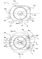
- the inner nozzle 12 comprises a metal casing 22, in which a refractory element 24 is cast which delimits the pouring channel 14, as shown in FIG. figure 1a .
- the metal casing 22 reinforces the refractory element 24, it is relatively thick, its walls having a thickness greater than 6 mm (millimeters).
- the metal casing delimits an internal nozzle plate, carrying a contact surface 26, shown in FIG. figure 1b , extending along a sliding plane parallel to the plane (X, Y).
- the contact surface 26 is intended to be in sealing contact with the sliding plate when the latter is slidably fed in the casting position, that is to say facing the inner nozzle 12, by the device 10.
- the surface sliding 26 is traversed by a pouring orifice 28, on which the casting channel 14 opens.
- the envelope 22, therefore the internal nozzle 12, comprises three flanges 30a, 30b, 30c for wedging the internal nozzle 12 against the frame 31 of the device 10, namely a first 30a, a second 30b and a third flange 30c.
- Each flange 30a, 30b, 30c has an upper surface 32a, 32b, 32c called said clamping surface, on which the clamping means 20 are intended to apply a clamping force, and a lower surface 34a, 34b, 34c said surface of support, intended to be in contact with the frame 31, in the example, the bearing surface extends in a substantially horizontal plane parallel to the plane (X, Y), called support plane.
- the clamping surfaces 32a, 32b, 32c are each arranged facing the bearing surfaces 34a, 34b, 34c, so that the clamping means 20 and the frame 31 sandwich the wedging edges 30a, 30b, 30c under the action of the clamping means 20.
- the wedging flanges 30a, 30b, 30c are distinct, i.e. they are separate, non-contiguous. More specifically in this example, the wedging flanges 30a, 30b, 30c protrude from a peripheral surface 36 of the plate of the inner nozzle 12, this surface 36 extending from the sliding surface 26 of the plate, preferably in a substantially vertical direction Z. Still in this example, the three wedging flanges 30a, 30b, 30c are made entirely of metal, that is to say that only metal between the bearing surfaces 34a, 34b, 34c and the clamping surfaces 32a, 32b, 32c.
- the inner nozzle 12 has two substantially longitudinal edges 40a, 40b and two substantially transverse edges 42a, 42b, namely a front transverse edge 42b and a rear transverse edge 42a. It further comprises a vertical central vertical plane P and the three wedging flanges 30a, 30b, 30c are arranged in Y on the periphery 36 of the nozzle 12, the base 44a of the Y being disposed in the central longitudinal plane P and the two branches 44b, 44c of Y being disposed on either side of this plane P.
- the second 30b and third 30c wedging flanges have a second 32b and a third 32c clamming surfaces, each of these second 32b and third 32c surfaces being disposed on either side of the longitudinal plane P.
- the second and third surfaces are arranged symmetrically.
- the surfaces 32b, 32c each have a center 32'b, 32'c positioned at an angle ⁇ (alpha) between 30 and 45 ° relative to the longitudinal plane P, with reference to the center 46 of the inner nozzle 12 , corresponding in the example to the center of the casting orifice 28.
- each of the second 32b and third 32c clamming surfaces is included in an angular sector ⁇ (beta) between 10 and 20 ° with reference to the center 46 of the inner nozzle 12.
- the first wedging flange 30a has a first clamping surface 32a passing through the longitudinal plane P of the nozzle 12. More specifically, the surface 32a extends substantially symmetrically with respect to the plane P, the center 32'a of this surface being positioned in the plane P.
- the surface 32a extends in a surface included in an angular sector ⁇ (gamma) between 14 and 52 ° with reference to the center 46 of the internal nozzle .
- the inner nozzle 12 further comprises gas injection means 48, the gas being injected into a groove in the contact surface of the inner nozzle, these means being disposed between the second 32b and the third 32c clamping surfaces.
- the means 48 comprise one or two channels opening onto a transverse vertical surface or transverse edge 49 forming part of the peripheral surface 36 and connecting the two wedging flanges 30b, 30c.
- the injected gas is, in this example, argon.
- the clamping means 20 comprise three clamping elements 50a, 50b, 50c, visible on the figure 2 , arranged at Y at the periphery of the inner nozzle 12, namely a first clamping element 50a at the base of the Y, disposed on the rear part of the central longitudinal plane P and a second 50b and a third 50c clamping elements, ends of the two branches of the Y, disposed on either side of the front portion of this plane P.
- the clamping means are arranged to exert their force on the transverse edges 42a, 42b of the inner nozzle .
- the clamping elements 50a, 50b, 50c have a configuration complementary to the configuration of the wedging flanges 30a, 30b, 30c. So, the first 50a, the second 50b and the third 50c clamping elements respectively exert a clamping force on the first 32a, second 32b and third 32c clamping surfaces described above.
- the clamping elements 50b, 50c are substantially identical. Only the structure of the element 50b will therefore be described, with reference to the Figures 2 and 2a .
- the clamping element 50b is rotatably mounted about an axis 52b fixed to the frame 31, extending substantially in the transverse direction Y or slightly inclined relative to this direction.
- the element 50b has a free end carrying a so-called clamping surface 54b intended to come into contact with the clamping surface 32b of the flange 30b, and to exert a clamping force on the surface 32b by pressing on this surface.
- the element 50b is actuated by a rotary member 56b (pivoting about a vertical axis) forming a cam in contact with the element 50b.
- the cam 56 when the cam 56 is rotated, it exerts a horizontal force on the free end of the element 50b, according to the arrow illustrated on the figure 2a , which has the effect of pivoting down the free end, so the surface 54b around the axis 52b.
- the downward pivoting of the surface 54b thus generates a clamping force on the surface 32b.
- the clamping element 50b does not exert only a downward clamping force, but also a horizontal force, intended to immobilize the rim 30b horizontally.
- Element 50a has a shape similar to that of element 50b shown in FIG. figure 2a , except that it extends over a larger area than the element 50b.
- the element 50a is rotatably mounted about an axis 52a fixed on the frame 31, extending in the transverse direction Y, and has a free end carrying a clamping surface 54a intended to come into contact with the clamping surface. 32a by pressing this surface.
- the element 50a is actuated differently from the element 50b, in particular by connecting rod-crank means.
- a rotary member 56a pivotally mounted about an axis in the example parallel to the Y direction and forming a cam in contact with a cylinder 58.
- the cylinder 58 can translate in the X direction.
- rod 60 forming a rod
- one end 62 is rotatably mounted on the cylinder 58
- the opposite end 64 is rotatably mounted around the free end of the clamping element 50a, the element 50a forming a crank.
- the cylinder 58 also constitutes a housing for a rod 66 biased by means 68 for biasing the clamping element 50a in the rest position, namely a compression spring.
- the clamping element 50a is movably mounted between a rest position and a clamping position, being actuated by the crank-rod system, as follows.
- the rest position is illustrated on the figure 5a .
- the movable member 56a is rotated about its axis, so that it moves the cylinder 58 in the horizontal direction illustrated by the arrow 70.
- the connecting rod 60 drives the element 50a in rotation about its axis 52a, as illustrated on the Figures 5b, 5c then 5d, so that the clamping surface 54a presses on the surface 32a and the element 50a takes its position of clamoring.
- the rod 66 abuts against the vertical wall of the flange 30a, which has the effect of compressing the spring 68 as illustrated in FIG. figure 5c then 5d. Thanks to this compression of the spring, the system can return to the rest position by simply rotating the cam member 56a. Indeed, when the element 50a is in the position of clamping, as illustrated on the figure 5d , the rotation of the member 56a allows the cylinder 58 to translate in the direction indicated by the arrow 72 under the action of the spring 68 which relaxes, and thus allows the clamping member to resume the position illustrated on the figure 5a .
- the device 10 further comprises, between the two clamping elements 50b, 50c, two gas injection channels for the nozzle 12, opening onto a vertical transverse surface 51 of the device 10.
- the injection channels of the device 10 are in the extension of the channels 48 of the nozzle 12, and the clamping position of the elements 50b, 50c ensures a particularly tight connection of these channels.
- the clamping method comprises a first step of abutment of the transverse vertical surface 49 of the nozzle 12, arranged between the clamping flanges. 30b, 30c, against the transverse vertical surface 51 of the frame 31 of the device 10, followed by an actuation of the first clamping element 50a in the clamping position.
- the first element 50a translates in accordance with the arrow 70 of the figure 5a , abuts against the flange 30a, which has the effect of pressing the inner nozzle 12 against the transverse edge 51 of the device before the device 10, so refer to it very precisely against this front edge.
- the setting of the clamping position by the clamping element 50a simultaneously generates the compression of seals arranged in the gas injection channels 48.
- the seals can be placed on the inner nozzle or on the device. They are preferably made of graphite.
- the translation along the arrow 70 allows a controlled compression of the joints.
- the clamping means exert their force on the transverse edges 42a, 42b of the inner nozzle, while the thrust means 18 exert their force on the longitudinal edges of the sliding plate, at the longitudinal edges 17a, 17b of the device 10. It comes out that pressure is exerted on substantially the entire circumference of the contact surface between the inner nozzle 12 and the sliding plate, resulting in a better seal.
Landscapes
- Engineering & Computer Science (AREA)
- Mechanical Engineering (AREA)
- Casting Support Devices, Ladles, And Melt Control Thereby (AREA)
- Continuous Casting (AREA)
- Furnace Housings, Linings, Walls, And Ceilings (AREA)
Priority Applications (28)
| Application Number | Priority Date | Filing Date | Title |
|---|---|---|---|
| EP10157126A EP2386368A1 (fr) | 2010-03-19 | 2010-03-19 | Busette interne pour le transfert de métal liquide contenu dans un récipient, système de clamage de cette busette et dispositif de coulée |
| RS20160015A RS54491B1 (en) | 2010-03-19 | 2011-03-17 | INNER Nozzle for the transfer of molten metal to the vessel, a system for clamping the said nozzle and a casting device |
| KR1020127026587A KR101790810B1 (ko) | 2010-03-19 | 2011-03-17 | 베셀에 담겨 있는 용탕을 운반하기 위한 내부 노즐, 이러한 노즐의 클램핑을 위한 시스템, 그리고 주조 장치 |
| RU2012136887/02A RU2593557C2 (ru) | 2010-03-19 | 2011-03-17 | Устройство для замены труб и внутреннее сопло для разливки расплавленного металла |
| MA35299A MA34152B1 (fr) | 2010-03-19 | 2011-03-17 | Buse intérieure pour transfert de métal en fusion contenu dans un récipient, système de serrage de ladite buse et dispositif de coulée |
| ES11709880.6T ES2563803T3 (es) | 2010-03-19 | 2011-03-17 | Buza interna para transferir metal fundido contenido en un recipiente, sistema para fijar dicha buza y dispositivo de colada |
| CU2012000134A CU24101B1 (es) | 2010-03-19 | 2011-03-17 | Dispositivo de intercambio de tubo, boquilla interna y carcasa metálica para revestir una boquilla interna para moldear metal fundido fuera de un recipiente. |
| AU2011229489A AU2011229489B2 (en) | 2010-03-19 | 2011-03-17 | Inner nozzle for transferring molten metal contained in a vessel, system for clamping said nozzle and casting device |
| US13/635,788 US9221098B2 (en) | 2010-03-19 | 2011-03-17 | Inner nozzle for transferring molten metal contained in a vessel, system for clamping said nozzle and casting device |
| EP11709880.6A EP2547475B1 (en) | 2010-03-19 | 2011-03-17 | Inner nozzle for transferring molten metal in a vessel, system for clamping said nozzle and casting device. |
| PL11709880T PL2547475T3 (pl) | 2010-03-19 | 2011-03-17 | Wewnętrzna dysza do przemieszczania stopionego metalu w zbiorniku, układ do mocowania wymienionej dyszy oraz urządzenie odlewnicze |
| SI201130694T SI2547475T1 (sl) | 2010-03-19 | 2011-03-17 | Notranja šoba za prenos topljene kovine v posodo, sistem za pritrditev omenjene šobe in vlivna naprava |
| NZ602093A NZ602093A (en) | 2010-03-19 | 2011-03-17 | Inner nozzle for transferring molten metal contained in a vessel, system for clamping said nozzle and casting device |
| MX2012010802A MX344894B (es) | 2010-03-19 | 2011-03-17 | Boquilla interna para transferir metal fundido contenido en un recipiente, sistema para sujetar dicha boquilla y dispositivo de fundición. |
| BR112012022127-2A BR112012022127B1 (pt) | 2010-03-19 | 2011-03-17 | Dispositivo de troca de tubo para conter e trocar uma válvula de vazamento intercambiável, válvula interna feita de um material de núcleo refratário para lingotar metal em fusão a partir de um vaso metalúrgico, conjunto de uma válvula interna e de um dispositivo de troca de tubo e revestimento metálico para revestir uma válvula interna |
| JP2013500370A JP5902666B2 (ja) | 2010-03-19 | 2011-03-17 | 容器内に含有された溶融金属流し込み用内部ノズル、前記ノズルのクランプシステム,及び鋳造装置 |
| CA2790274A CA2790274C (en) | 2010-03-19 | 2011-03-17 | Inner nozzle for transferring molten metal contained in a vessel, system for clamping said nozzle and casting device. |
| PCT/EP2011/001326 WO2011113599A1 (en) | 2010-03-19 | 2011-03-17 | Inner nozzle for transferring molten metal contained in a vessel, system for clamping said nozzle and casting device |
| UAA201210223A UA108633C2 (uk) | 2010-03-19 | 2011-03-17 | Внутрішнє сопло для перенесення розплавленого металу, що міститься в резервуарі, система для притискання вказаного сопла до ливарного пристрою |
| MYPI2012003887A MY156535A (en) | 2010-03-19 | 2011-03-17 | Inner nozzle for transferring molten metal contained in a vessel, system for clamping said nozzle and casting device |
| TW100109323A TWI527642B (zh) | 2010-03-19 | 2011-03-18 | 管交換裝置、內噴嘴、內噴嘴及管交換裝置之組合以及金屬殼體 |
| ARP110100903A AR080696A1 (es) | 2010-03-19 | 2011-03-18 | Dispositivo de intercambio de tubos, boquilla interna para transferir metal fundido contenido en un recipiente y carcasa metalica para revestir dicha boquilla. |
| CN201110067945.1A CN102189233B (zh) | 2010-03-19 | 2011-03-21 | 传输容器中容纳的熔融金属的内水口、系统及浇铸装置 |
| CN2011200758641U CN202087822U (zh) | 2010-03-19 | 2011-03-21 | 浇钢水口交换装置 |
| CL2012002395A CL2012002395A1 (es) | 2010-03-19 | 2012-08-30 | Dispositivo de intercambio de tubo para sostener y reemplazar una boquilla de vertimiento intercambiable porque sirve para moldear metal fundido fuera de un recipiente, medios para recibir y sujetar, medios para desplazar y presion; boquilla interna; ensamble y carcasa metalica. |
| EG2012091571A EG26994A (en) | 2010-03-19 | 2012-09-12 | Inner nozzle for transferring molten metal contained in a vessel, system for clamping said nozzle and casting device |
| US14/943,761 US9808863B2 (en) | 2010-03-19 | 2015-11-17 | Tube exchange device for holding and replacing a pouring nozzle, and assembly of a tube exchange device and a pouring nozzle |
| HRP20160219T HRP20160219T1 (hr) | 2010-03-19 | 2016-03-01 | Unutarnja mlaznica za prijenos rastaljenog metala u posudi, sustav za držanje navedene mlaznice i odlijevanje |
Applications Claiming Priority (1)
| Application Number | Priority Date | Filing Date | Title |
|---|---|---|---|
| EP10157126A EP2386368A1 (fr) | 2010-03-19 | 2010-03-19 | Busette interne pour le transfert de métal liquide contenu dans un récipient, système de clamage de cette busette et dispositif de coulée |
Publications (1)
| Publication Number | Publication Date |
|---|---|
| EP2386368A1 true EP2386368A1 (fr) | 2011-11-16 |
Family
ID=42340611
Family Applications (2)
| Application Number | Title | Priority Date | Filing Date |
|---|---|---|---|
| EP10157126A Withdrawn EP2386368A1 (fr) | 2010-03-19 | 2010-03-19 | Busette interne pour le transfert de métal liquide contenu dans un récipient, système de clamage de cette busette et dispositif de coulée |
| EP11709880.6A Active EP2547475B1 (en) | 2010-03-19 | 2011-03-17 | Inner nozzle for transferring molten metal in a vessel, system for clamping said nozzle and casting device. |
Family Applications After (1)
| Application Number | Title | Priority Date | Filing Date |
|---|---|---|---|
| EP11709880.6A Active EP2547475B1 (en) | 2010-03-19 | 2011-03-17 | Inner nozzle for transferring molten metal in a vessel, system for clamping said nozzle and casting device. |
Country Status (25)
| Country | Link |
|---|---|
| US (2) | US9221098B2 (es) |
| EP (2) | EP2386368A1 (es) |
| JP (1) | JP5902666B2 (es) |
| KR (1) | KR101790810B1 (es) |
| CN (2) | CN202087822U (es) |
| AR (1) | AR080696A1 (es) |
| AU (1) | AU2011229489B2 (es) |
| BR (1) | BR112012022127B1 (es) |
| CA (1) | CA2790274C (es) |
| CL (1) | CL2012002395A1 (es) |
| CU (1) | CU24101B1 (es) |
| EG (1) | EG26994A (es) |
| ES (1) | ES2563803T3 (es) |
| HR (1) | HRP20160219T1 (es) |
| MA (1) | MA34152B1 (es) |
| MX (1) | MX344894B (es) |
| MY (1) | MY156535A (es) |
| NZ (1) | NZ602093A (es) |
| PL (1) | PL2547475T3 (es) |
| RS (1) | RS54491B1 (es) |
| RU (1) | RU2593557C2 (es) |
| SI (1) | SI2547475T1 (es) |
| TW (1) | TWI527642B (es) |
| UA (1) | UA108633C2 (es) |
| WO (1) | WO2011113599A1 (es) |
Families Citing this family (8)
| Publication number | Priority date | Publication date | Assignee | Title |
|---|---|---|---|---|
| EP2386368A1 (fr) * | 2010-03-19 | 2011-11-16 | Vesuvius Group S.A | Busette interne pour le transfert de métal liquide contenu dans un récipient, système de clamage de cette busette et dispositif de coulée |
| AR086749A1 (es) * | 2011-06-28 | 2014-01-22 | Vesuvius Group Sa | Dispositivo de compuerta de corte, artesa y buza de colada |
| AR099467A1 (es) * | 2014-02-19 | 2016-07-27 | Vesuvius Group Sa | Revestimiento de cuchara de colada para colada de metales, conjunto de partes de conjunto de acoplamiento para acoplar dicho revestimiento de cuchara de colada a una cuchara, instalación de colada de metales y proceso de acoplamiento |
| USD781940S1 (en) * | 2015-01-28 | 2017-03-21 | Krosaki Harima Corporation | Sliding nozzle plate |
| CN106493346B (zh) * | 2016-12-12 | 2019-09-13 | 华耐国际(宜兴)高级陶瓷有限公司 | 一种连铸用浸入式水口 |
| CN109877307B (zh) | 2017-11-10 | 2021-11-02 | 维苏威集团有限公司 | 自锁式内管口系统 |
| CN112317713B (zh) * | 2020-11-04 | 2022-10-18 | 中冶赛迪信息技术(重庆)有限公司 | 一种连铸控制方法及系统 |
| CN113102740B (zh) * | 2021-04-13 | 2021-11-02 | 广州立中锦山合金有限公司 | 一种用于铝液转运的可升降导流装置及其使用方法 |
Citations (4)
| Publication number | Priority date | Publication date | Assignee | Title |
|---|---|---|---|---|
| EP0441927B1 (fr) * | 1989-08-30 | 1994-12-14 | International Industrial Engineering S.A. | Dispositif de coulee obturable pour un conteneur siderurgique ou metallurgique |
| EP1289696A1 (en) | 2000-04-21 | 2003-03-12 | Vesuvius Crucible Company | One-piece inner nozzle and clamping device for holding such a nozzle |
| EP1439016A1 (fr) * | 2003-01-20 | 2004-07-21 | Vesuvius Group S.A | Tube de coulée, dispositif de clamage d'un tube de coulée et installation de coulée |
| DE202005017531U1 (de) * | 2005-11-09 | 2006-02-16 | Knöllinger FLO-TEC GmbH | Gießpfannenschieber |
Family Cites Families (18)
| Publication number | Priority date | Publication date | Assignee | Title |
|---|---|---|---|---|
| GB1472532A (en) * | 1973-04-27 | 1977-05-04 | Didier Werke Ag | Sliding gate nozzles for metallurgical vessels |
| DE2821839B2 (de) * | 1978-05-19 | 1981-04-16 | Stopine AG, Zug | Schiebeverschluß für den Ausguß an Metallschmelze enthaltenden Behältern |
| EP0122904A3 (fr) | 1983-03-21 | 1987-11-19 | Vesuvius International Corporation | Dispositif de fermeture coulissant pour conteneur sidérurgique ou métallurgique |
| CA1251642A (en) * | 1983-11-02 | 1989-03-28 | Kazumi Arakawa | Molten metal discharging device |
| US5044533A (en) | 1990-10-01 | 1991-09-03 | Flo-Con Systems, Inc. | Clamp for bandless refractory and method |
| WO1992000821A1 (fr) * | 1990-07-04 | 1992-01-23 | International Industrial Engineering S.A. | Dispositif ameliore d'amenee et d'echange d'un tube de coulee |
| US5211857A (en) | 1990-10-31 | 1993-05-18 | Leco Corporation | Gate safety arrangement |
| DE9408700U1 (de) | 1993-07-06 | 1994-09-08 | Stopinc Ag | Vorrichtung zum Anschließen und Wechseln eines Gießrohres an ein Metallschmelze enthaltendes Gefäß |
| BE1007317A3 (fr) * | 1993-07-27 | 1995-05-16 | Int Ind Eng Sa | Dispositif d'amenee et d'echange d'un tube de coulee dans une installation de coulee continue a brames minces. |
| JP3322461B2 (ja) | 1993-10-26 | 2002-09-09 | 黒崎播磨株式会社 | スライディングノズル装置のプレートれんが着脱装置 |
| FR2740368B1 (fr) * | 1995-10-27 | 1997-12-12 | Vesuvius France Sa | Procede de reutilisation de plaques de fermeture a tiroir et plaque pour cette fermeture |
| CN2621858Y (zh) * | 2003-05-02 | 2004-06-30 | 青岛双鹰耐火材料有限公司 | 防粘连快速更换浸入式水口 |
| CN2637038Y (zh) * | 2003-07-13 | 2004-09-01 | 张坤东 | 液压式连铸用水口快换机构 |
| CN2659592Y (zh) * | 2003-11-11 | 2004-12-01 | 卫辉熔金耐火材料有限责任公司 | 炼钢板坯连铸中间包水口快速更换装置 |
| KR20090095568A (ko) * | 2006-12-11 | 2009-09-09 | 스토핑크 아크티엔게젤샤프트 | 야금용기용 미끄럼 클로져 |
| CN201201049Y (zh) | 2008-06-17 | 2009-03-04 | 濮阳濮耐高温材料(集团)股份有限公司 | 一种连铸用中间包透气上水口及其固定所用的夹持头 |
| EP2371471A1 (fr) * | 2010-03-19 | 2011-10-05 | Vesuvius Group S.A | Busette interne pour le transfert de métal liquide contenu dans un récipient métallurgique et dispositif de transfert de métal liquide. |
| EP2386368A1 (fr) * | 2010-03-19 | 2011-11-16 | Vesuvius Group S.A | Busette interne pour le transfert de métal liquide contenu dans un récipient, système de clamage de cette busette et dispositif de coulée |
-
2010
- 2010-03-19 EP EP10157126A patent/EP2386368A1/fr not_active Withdrawn
-
2011
- 2011-03-17 MA MA35299A patent/MA34152B1/fr unknown
- 2011-03-17 US US13/635,788 patent/US9221098B2/en active Active
- 2011-03-17 UA UAA201210223A patent/UA108633C2/ru unknown
- 2011-03-17 CA CA2790274A patent/CA2790274C/en active Active
- 2011-03-17 AU AU2011229489A patent/AU2011229489B2/en active Active
- 2011-03-17 SI SI201130694T patent/SI2547475T1/sl unknown
- 2011-03-17 KR KR1020127026587A patent/KR101790810B1/ko active IP Right Grant
- 2011-03-17 BR BR112012022127-2A patent/BR112012022127B1/pt active IP Right Grant
- 2011-03-17 MY MYPI2012003887A patent/MY156535A/en unknown
- 2011-03-17 RS RS20160015A patent/RS54491B1/en unknown
- 2011-03-17 RU RU2012136887/02A patent/RU2593557C2/ru active
- 2011-03-17 WO PCT/EP2011/001326 patent/WO2011113599A1/en active Application Filing
- 2011-03-17 MX MX2012010802A patent/MX344894B/es active IP Right Grant
- 2011-03-17 JP JP2013500370A patent/JP5902666B2/ja active Active
- 2011-03-17 ES ES11709880.6T patent/ES2563803T3/es active Active
- 2011-03-17 PL PL11709880T patent/PL2547475T3/pl unknown
- 2011-03-17 EP EP11709880.6A patent/EP2547475B1/en active Active
- 2011-03-17 NZ NZ602093A patent/NZ602093A/en unknown
- 2011-03-17 CU CU2012000134A patent/CU24101B1/es active IP Right Grant
- 2011-03-18 TW TW100109323A patent/TWI527642B/zh active
- 2011-03-18 AR ARP110100903A patent/AR080696A1/es active IP Right Grant
- 2011-03-21 CN CN2011200758641U patent/CN202087822U/zh not_active Expired - Lifetime
- 2011-03-21 CN CN201110067945.1A patent/CN102189233B/zh active Active
-
2012
- 2012-08-30 CL CL2012002395A patent/CL2012002395A1/es unknown
- 2012-09-12 EG EG2012091571A patent/EG26994A/xx active
-
2015
- 2015-11-17 US US14/943,761 patent/US9808863B2/en active Active
-
2016
- 2016-03-01 HR HRP20160219T patent/HRP20160219T1/hr unknown
Patent Citations (5)
| Publication number | Priority date | Publication date | Assignee | Title |
|---|---|---|---|---|
| EP0441927B1 (fr) * | 1989-08-30 | 1994-12-14 | International Industrial Engineering S.A. | Dispositif de coulee obturable pour un conteneur siderurgique ou metallurgique |
| EP1289696A1 (en) | 2000-04-21 | 2003-03-12 | Vesuvius Crucible Company | One-piece inner nozzle and clamping device for holding such a nozzle |
| EP1289696B1 (en) * | 2000-04-21 | 2005-05-11 | Vesuvius Crucible Company | One-piece inner nozzle and clamping device for holding such a nozzle |
| EP1439016A1 (fr) * | 2003-01-20 | 2004-07-21 | Vesuvius Group S.A | Tube de coulée, dispositif de clamage d'un tube de coulée et installation de coulée |
| DE202005017531U1 (de) * | 2005-11-09 | 2006-02-16 | Knöllinger FLO-TEC GmbH | Gießpfannenschieber |
Also Published As
Similar Documents
| Publication | Publication Date | Title |
|---|---|---|
| EP2386368A1 (fr) | Busette interne pour le transfert de métal liquide contenu dans un récipient, système de clamage de cette busette et dispositif de coulée | |
| EP0373997B1 (fr) | Conteneur de stockage pour déchets radioactifs | |
| EP2371471A1 (fr) | Busette interne pour le transfert de métal liquide contenu dans un récipient métallurgique et dispositif de transfert de métal liquide. | |
| BE1001330A3 (fr) | Plaque de fermeture en matiere refractaire et fermeture a glissement pour busette de coulee d'un recipient contenant du metal en fusion. | |
| EP2368655A1 (fr) | Plaque pour le transfert de métal liquide contenu dans un récipient métallurgique, bâti et dispositif de changement d'une telle plaque | |
| EP0312460B1 (fr) | Dipositif de raccordement déconnectable de deux enceintes étanches | |
| FR2745211A1 (fr) | Repartiteur equipe d'un changeur de tube et plaque pour le changeur de tube | |
| EP1517032B1 (fr) | Volet chaud commandé de tuyère axisymétrique de turboréacteur | |
| CA2742862C (fr) | Tube de poche pour installation de coulee de metal liquide | |
| EP0621098A1 (fr) | Dispositif de coulée comportant une liaison sans ciment d'un conteneur métallurgique à un obturateur à tiroir et procédé de mise en oeuvre de ce dispositif | |
| EP1600285B1 (fr) | Dispositif de fabrication de pastilles par compression | |
| WO2015158965A1 (fr) | Moule en tandem pour la réalisation de pièces injectées en matière synthétique | |
| CA2021947C (fr) | Fixation pour ski de fond et tampon elastique destine a une telle fixation | |
| EP2188178B1 (fr) | Nacelle de turboréacteur, destinée à équiper un aéronef | |
| EP1899134B1 (fr) | Dispositif d'injection moulage a chauffage de buse indexe | |
| CA2742638C (fr) | Element de coulee reutilisable | |
| WO2010055256A1 (fr) | Outillage a éléments articulés équipé d'un dispositif de verrouillage | |
| EP4171916A1 (fr) | Dispositif d'éjection pour moule comprenant une chaîne de maillons coulissants et une cale de réglage | |
| EP1799424B1 (fr) | Dispositif d'injection-moulage a appui reparti | |
| EP2186632A1 (fr) | Système de montage de poinçons coulissants dans une presse à comprimés | |
| EP1637939B1 (fr) | Palette d'ancre pour mouvement d' horlogerie | |
| WO1997031736A1 (fr) | Unite coulissante pour un conteneur metallurgique, et plaque associee | |
| FR2785226A1 (fr) | Manchon intermediaire pour cylindre d'impression | |
| FR3050774A1 (fr) | Machine hydraulique debrayable et vehicule equipe d'une telle machine | |
| FR3135476A1 (fr) | Tige d’entretoise pour banches de coffrage et procédé de montage et démontage d’une telle tige d’entretoise |
Legal Events
| Date | Code | Title | Description |
|---|---|---|---|
| AK | Designated contracting states |
Kind code of ref document: A1 Designated state(s): AT BE BG CH CY CZ DE DK EE ES FI FR GB GR HR HU IE IS IT LI LT LU LV MC MK MT NL NO PL PT RO SE SI SK SM TR |
|
| AX | Request for extension of the european patent |
Extension state: AL BA ME RS |
|
| PUAI | Public reference made under article 153(3) epc to a published international application that has entered the european phase |
Free format text: ORIGINAL CODE: 0009012 |
|
| STAA | Information on the status of an ep patent application or granted ep patent |
Free format text: STATUS: THE APPLICATION IS DEEMED TO BE WITHDRAWN |
|
| 18D | Application deemed to be withdrawn |
Effective date: 20120517 |