EP2385171B1 - Yankeezylinder zum Trocknen einer Faserstoffbahn - Google Patents
Yankeezylinder zum Trocknen einer Faserstoffbahn Download PDFInfo
- Publication number
- EP2385171B1 EP2385171B1 EP11002527A EP11002527A EP2385171B1 EP 2385171 B1 EP2385171 B1 EP 2385171B1 EP 11002527 A EP11002527 A EP 11002527A EP 11002527 A EP11002527 A EP 11002527A EP 2385171 B1 EP2385171 B1 EP 2385171B1
- Authority
- EP
- European Patent Office
- Prior art keywords
- central shaft
- end cover
- connecting flange
- cylinder
- opening
- Prior art date
- Legal status (The legal status is an assumption and is not a legal conclusion. Google has not performed a legal analysis and makes no representation as to the accuracy of the status listed.)
- Active
Links
Images

Classifications
-
- F—MECHANICAL ENGINEERING; LIGHTING; HEATING; WEAPONS; BLASTING
- F26—DRYING
- F26B—DRYING SOLID MATERIALS OR OBJECTS BY REMOVING LIQUID THEREFROM
- F26B13/00—Machines and apparatus for drying fabrics, fibres, yarns, or other materials in long lengths, with progressive movement
- F26B13/10—Arrangements for feeding, heating or supporting materials; Controlling movement, tension or position of materials
- F26B13/14—Rollers, drums, cylinders; Arrangement of drives, supports, bearings, cleaning
- F26B13/18—Rollers, drums, cylinders; Arrangement of drives, supports, bearings, cleaning heated or cooled, e.g. from inside, the material being dried on the outside surface by conduction
-
- D—TEXTILES; PAPER
- D21—PAPER-MAKING; PRODUCTION OF CELLULOSE
- D21F—PAPER-MAKING MACHINES; METHODS OF PRODUCING PAPER THEREON
- D21F5/00—Dryer section of machines for making continuous webs of paper
- D21F5/02—Drying on cylinders
- D21F5/021—Construction of the cylinders
-
- Y—GENERAL TAGGING OF NEW TECHNOLOGICAL DEVELOPMENTS; GENERAL TAGGING OF CROSS-SECTIONAL TECHNOLOGIES SPANNING OVER SEVERAL SECTIONS OF THE IPC; TECHNICAL SUBJECTS COVERED BY FORMER USPC CROSS-REFERENCE ART COLLECTIONS [XRACs] AND DIGESTS
- Y10—TECHNICAL SUBJECTS COVERED BY FORMER USPC
- Y10T—TECHNICAL SUBJECTS COVERED BY FORMER US CLASSIFICATION
- Y10T29/00—Metal working
- Y10T29/49—Method of mechanical manufacture
- Y10T29/49826—Assembling or joining
Definitions
- the subject of the invention is a Yankee cylinder made of steel for drying a fibrous web with a cylindrical steel shell, which is connected in each case at its ends with a first and a second end cover, wherein the end cover each having an opening in its center.
- the Yankee cylinder has a central shaft consisting of two journal, a central part, a first connecting flange for connecting the central shaft to the first end cap and a second connecting flange for connecting the central shaft to the second end cap.
- the subject matter of the invention also forms a production method for the Yankee cylinder according to the invention.
- Yankee cylinders usually have a very large diameter. They are heated by steam and are difficult to produce because of the high requirements in terms of internal pressures, tightness and large diameter.
- Yankee cylinders have, for example, the following dimensions: Cylinder diameter: 3000 mm to 5500 mm Hollow shaft diameter: 1500 mm to 1800 mm Cylinder width: 6000 mm to 7500 mm Cylinder mass: 40 t to 95 t
- Yankee cylinders made of steel are already known.
- a Yankee cylinder consists of a cylindrical shell surface, which is closed at the ends with differently shaped end caps. The two covers can be bolted to the cylinder jacket or welded.
- a Yankee cylinder is rotatably supported by pins and has in its interior a hollow shaft or axis through which steam is introduced for heating in the cylinder or exhaust steam and condensate can be removed.
- the WO2008 / 105005 discloses a Yankee cylinder made of steel with a multi-part central shaft. This means that the two bearing journals of the Yankee are fastened to the covers separately from an internal hollow shaft, for example by means of screws (see Fig.1 ).
- This embodiment has the disadvantage that in addition a great many screws and flanges are required, which weaken the component.
- several components are to be machined, which are provided with tolerances and this can lead to an imprecise camp escape.
- the lids Due to the safety regulations for the production of pressure vessels, the lids must be welded to the shell on both sides, ie both on the inside and on the outside.
- the conventional assembly process has the disadvantage that the root welding between the second cover and the cylinder jacket in the cylinder interior is only possible through the entry through the manhole in the lid. On the one hand, this results in more difficult working conditions for the welding personnel (lack of light, air and space) and, on the other hand, a significantly higher risk of accidents.
- the aim of the invention is to disclose a steel Yankee cylinder which can be manufactured more easily.
- the central shaft is assembled before it is inserted into the steel jacket.
- the central shaft is in one piece after its production.
- the diameter of the first connecting flange is smaller than the diameter of the opening of the second end cover, so that the central shaft can be pushed through this opening in the Yankee cylinder.
- Due to the one-piece central shaft the steel shell of the Yankee cylinder can first be connected to the two end caps, preferably welded.
- the Yankee interior is easily accessible, as the two openings in the covers are quite large ( ⁇ 1500 mm), so the welding work in Yankee interior are easy to carry out. Only after connecting the end cover with the steel shell, the one-piece central shaft is inserted into the cylinder and connected thereto. Furthermore, due to the smaller number of components easier handling during assembly.
- the diameter of the first connection flange is larger than the opening of the first end cover.
- the first connecting flange is thus after the onset of the central shaft on the inside of the first end cap and can be easily connected to this, for example screwed.
- the diameter of the second connecting flange is greater than the opening of the second end cap, since, after insertion of the central shaft, the second connecting flange bears against the outer end of the second end cap and can easily be connected (for example screwed) to it.
- the central shaft thus has connecting flanges with different diameters at both ends.
- the connecting flange has a larger diameter at the driver end than the connecting flange at the drive end. Due to this special construction of the central shaft and a corresponding screwing of the central shaft with the end covers also the Possibility to exchange the central shaft non-destructively.
- the prior art does not disclose any embodiments that make it possible, for example in the case of a tightness problem, to expand the shaft without destroying the covers and thus usually also the cylinder jacket.
- the aim of the invention is also to disclose a simpler manufacturing method for a Yankee cylinder.
- the central shaft is therefore only then inserted into the cylinder when both end caps are firmly connected to the cylinder jacket. Welding to connect the jacket to the covers no longer has to be done through the manhole.
- the connecting flanges of the central shaft can either be screwed or welded to the end caps.
- a screw connection offers the possibility of easy replacement of the central shaft.
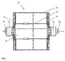
- a Yankee cylinder 11 is shown according to the prior art. It consists of a cylindrical steel shell 12, which is welded to the two end caps 13.
- the Yankee cylinder has a multi-part central shaft 14, it consists of the two bearing pins 15 and a cylindrical connecting piece 17 in the interior of the cylinder.
- the two bearing pins 15 and the connecting piece 17 are screwed to the end caps 13.
- the two bearing journals 15 are rotatably mounted in the roller bearings 16.
- the steel shell 12 is first connected to one of the two end caps 13. Thereafter, the connector 17 (hollow shaft) is inserted into the cylinder and bolted to the end cap 13.
- the second end cap 13 is placed on the steel shell 12 and welded to the cylinder jacket or screwed to the connector 17.
- the welding of the steel shell 12 with the end caps 13 must be done from the inside and the outside of the cylinder, therefore, the welding of the second end cap 13 must be performed with the steel shell 12 via a manhole in the end cap 13.
- the two bearing journals 15 are screwed to the respective end caps.
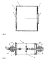
- Fig. 2 shows the cylindrical steel shell 2 according to the invention of the Yankee cylinder.
- the steel shell 2 is connected to a first end cover 3 and a second end cover 4.
- the two end covers (3, 4) each have in their center a circular opening (5, 6) for receiving the central shaft 7.
- the central shaft 7 is in Fig. 3 shown. It has a one-piece construction. By this it is meant that the central shaft 7 optionally forms, after its manufacture, a number of parts which are inserted into the steel shell 2.
- the one-piece central shaft 7 consists of the bearing pin 20, of the two connecting flanges 8 and 9 and of a central part 21. This central shaft 7 is assembled before it is inserted into the steel shell 2.
- the central shaft is rotatably supported by the bearings 10. Via the steam supply 18, steam can be supplied to the Yankee cylinder during operation. Abdampf or condensate is removed via the line 19.
- Fig. 4 the Yankee cylinder 1 is shown in the assembled state.
- the cylindrical steel shell 2 is first placed with one end on the first end cover 3 and connected thereto, for example screwed or welded. Thereafter, the second end cover 4 is connected to the other end of the cylindrical steel shell 2.
- the two end covers 3 and 4 each have the openings 5 and 6 for receiving the central shaft 7.
- the opening 5 in the first end cover 3 is slightly smaller than the opening 6 in the second end cover 4.
- the preassembled one-piece central shaft 7 is inserted through the opening 6 of the second end cover 4 in the steel shell 2.
- the diameter of the first connecting flange 8 of the central shaft 7 must be smaller than the opening 6, so that the central shaft 7 can be inserted into the cylinder.
- the diameter of the first connecting flange 8 is slightly larger than the opening 5 in the first end cap 3.
- the connecting flange 8 is after the insertion of the central shaft 7 on the inside of the first end cap 3 (see Fig. 4 ).
- the first end cover 3 can be easily screwed from the outside to the first connecting flange 8.
- the diameter of the second connecting flange 9 is slightly larger than the opening 6 of the second end cover 4. This results in the connecting flange. 9 after insertion of the central shaft 7 in the cylinder on the outside of the end cover 4 and can be screwed with this problem. This special construction also allows easy removal of the central shaft 7.
- the condensate lines 22 are mounted only after installation of the central shaft 7.
Landscapes
- Engineering & Computer Science (AREA)
- Textile Engineering (AREA)
- Mechanical Engineering (AREA)
- General Engineering & Computer Science (AREA)
- Paper (AREA)
- Drying Of Solid Materials (AREA)
Priority Applications (1)
| Application Number | Priority Date | Filing Date | Title |
|---|---|---|---|
| PL11002527T PL2385171T3 (pl) | 2010-05-06 | 2011-03-28 | Cylinder yankee do suszenia wstęgi substancji włóknistej |
Applications Claiming Priority (1)
| Application Number | Priority Date | Filing Date | Title |
|---|---|---|---|
| AT0076310A AT509053B1 (de) | 2010-05-06 | 2010-05-06 | Yankeezylinder zum trocknen einer faserstoffbahn |
Publications (2)
| Publication Number | Publication Date |
|---|---|
| EP2385171A1 EP2385171A1 (de) | 2011-11-09 |
| EP2385171B1 true EP2385171B1 (de) | 2012-09-19 |
Family
ID=43919790
Family Applications (1)
| Application Number | Title | Priority Date | Filing Date |
|---|---|---|---|
| EP11002527A Active EP2385171B1 (de) | 2010-05-06 | 2011-03-28 | Yankeezylinder zum Trocknen einer Faserstoffbahn |
Country Status (6)
| Country | Link |
|---|---|
| US (1) | US8919008B2 (pl) |
| EP (1) | EP2385171B1 (pl) |
| CN (1) | CN102234953B (pl) |
| AT (1) | AT509053B1 (pl) |
| CA (1) | CA2737692C (pl) |
| PL (1) | PL2385171T3 (pl) |
Cited By (1)
| Publication number | Priority date | Publication date | Assignee | Title |
|---|---|---|---|---|
| WO2015000648A1 (de) | 2013-07-05 | 2015-01-08 | Voith Patent Gmbh | GROßZYLINDER-TROCKENWALZE SOWIE VERFAHREN ZUM HERSTELLEN EINER GROßZYLINDER-TROCKENWALZE |
Families Citing this family (10)
| Publication number | Priority date | Publication date | Assignee | Title |
|---|---|---|---|---|
| SE1251287A1 (sv) * | 2012-11-13 | 2014-05-06 | Valmet Aktiebolag | Yankeecylinder gjord av stål |
| WO2015014515A1 (de) * | 2013-08-01 | 2015-02-05 | Voith Patent Gmbh | GROßZYLINDER-TROCKENWALZE SOWIE VERFAHREN ZUM HERSTELLEN EINER GROßZYLINDER-TROCKENWALZE |
| CN105463921A (zh) * | 2015-03-24 | 2016-04-06 | 溧阳市江南烘缸制造有限公司 | 一种钢制扬克式烘缸 |
| CN104792149A (zh) * | 2015-04-27 | 2015-07-22 | 江苏华东造纸机械有限公司 | 工业钢制焊接加热烘筒 |
| CN105200839A (zh) * | 2015-10-12 | 2015-12-30 | 白城福佳科技有限公司 | 一种造纸机及其烘缸 |
| SE540216C2 (en) * | 2016-03-31 | 2018-05-02 | Valmet Oy | A yankee drying cylinder for drying a fibrous web and a method of making a yankee drying cylinder |
| US10533283B2 (en) * | 2017-07-18 | 2020-01-14 | Valmet, Inc. | Reduced diameter foraminous exhaust cylinder |
| DE102018119489A1 (de) | 2018-08-10 | 2019-06-27 | Voith Patent Gmbh | Trockenwalze |
| CN112665343B (zh) * | 2020-12-25 | 2022-10-28 | 平江县绿宝堂中药材发展有限公司 | 一种用于中药材枸杞烘干装置 |
| CN113427219B (zh) * | 2021-07-19 | 2023-07-14 | 溧阳市江南烘缸制造有限公司 | 一种大型钢制扬克烘缸的制造方法 |
Family Cites Families (16)
| Publication number | Priority date | Publication date | Assignee | Title |
|---|---|---|---|---|
| GB685009A (en) * | 1949-10-31 | 1952-12-31 | Voith Gmbh J M | Improvements in and relating to drying cylinders, more particularly for paper making machines |
| US3022047A (en) * | 1957-11-04 | 1962-02-20 | Swaney Robert Casper | Stabil-heat drier |
| US3633662A (en) * | 1970-01-16 | 1972-01-11 | Beloit Corp | Dryer drum assembly |
| US3919783A (en) * | 1971-03-29 | 1975-11-18 | Anthony J Cirrito | Method for hot gas heat transfer, particularly for paper drying |
| US3808700A (en) * | 1972-12-26 | 1974-05-07 | Kimberly Clark Co | Rotary drying drum |
| US4196689A (en) | 1977-01-17 | 1980-04-08 | J. M. Voith Gmbh | Apparatus for drying paper webs or the like |
| DE2707923A1 (de) | 1977-02-24 | 1978-08-31 | Voith Gmbh J M | Trockenzylinder fuer bahnen aus zellstoff oder papier |
| AT383837B (de) * | 1982-05-26 | 1987-08-25 | Voith Gmbh J M | Trockenzylinder fuer papiermaschinen |
| FI960702A0 (fi) * | 1996-02-16 | 1996-02-16 | Ppr Consulting Ltd Oy | Torkanordning foer fiberbanor |
| CN2283669Y (zh) * | 1996-09-25 | 1998-06-10 | 程永智 | 烘缸进汽头装置 |
| US6683284B2 (en) * | 2002-03-22 | 2004-01-27 | Metso Paper Karlstad Ab | Thermal roll for papermaking with a fluid circulation system and method therefor |
| DE10252110A1 (de) * | 2002-11-08 | 2004-05-27 | Siemens Ag | Direktantrieb für einen Zylinder |
| DE102006020242A1 (de) * | 2006-04-27 | 2007-10-31 | Voith Patent Gmbh | Walzenantriebsende und Verfahren zur Montage desselben |
| PL2126203T3 (pl) | 2007-03-01 | 2012-11-30 | Toscotec S P A | Cylinder YANKEE do maszyny papierniczej |
| CN201265122Y (zh) * | 2008-05-30 | 2009-07-01 | 焦作市崇义轻工机械有限公司 | 造纸机用铸铁烘缸端盖 |
| IT1395588B1 (it) * | 2009-09-09 | 2012-10-16 | Toscotec S P A | "cilindro monolucido coibentato" |
-
2010
- 2010-05-06 AT AT0076310A patent/AT509053B1/de active
-
2011
- 2011-03-28 EP EP11002527A patent/EP2385171B1/de active Active
- 2011-03-28 PL PL11002527T patent/PL2385171T3/pl unknown
- 2011-04-20 CA CA2737692A patent/CA2737692C/en active Active
- 2011-04-27 CN CN201110123431.3A patent/CN102234953B/zh active Active
- 2011-05-06 US US13/068,246 patent/US8919008B2/en active Active
Cited By (3)
| Publication number | Priority date | Publication date | Assignee | Title |
|---|---|---|---|---|
| WO2015000648A1 (de) | 2013-07-05 | 2015-01-08 | Voith Patent Gmbh | GROßZYLINDER-TROCKENWALZE SOWIE VERFAHREN ZUM HERSTELLEN EINER GROßZYLINDER-TROCKENWALZE |
| US9885152B2 (en) | 2013-07-05 | 2018-02-06 | Voith Patent Gmbh | Large cylinder drying roller and method for producing a large cylinder drying roller |
| US10179974B2 (en) | 2013-07-05 | 2019-01-15 | Voith Patent Gmbh | Method for producing a large cylinder drying roller |
Also Published As
| Publication number | Publication date |
|---|---|
| US8919008B2 (en) | 2014-12-30 |
| PL2385171T3 (pl) | 2013-02-28 |
| EP2385171A1 (de) | 2011-11-09 |
| US20140068961A1 (en) | 2014-03-13 |
| CN102234953B (zh) | 2016-03-30 |
| AT509053A4 (de) | 2011-06-15 |
| CA2737692C (en) | 2017-04-18 |
| AT509053B1 (de) | 2011-06-15 |
| CA2737692A1 (en) | 2011-11-06 |
| CN102234953A (zh) | 2011-11-09 |
Similar Documents
| Publication | Publication Date | Title |
|---|---|---|
| AT509053B1 (de) | Yankeezylinder zum trocknen einer faserstoffbahn | |
| EP3196356B1 (de) | Trockenwalze | |
| DE202007019227U1 (de) | Yankeezylinder für eine Maschine zur Papierherstellung | |
| AT511232B1 (de) | Verfahren zur herstellung eines yankeezylinders | |
| DE69820883T2 (de) | Gewalzter lagerlaufring und verfahren zu seiner herstellung | |
| CH671420A5 (pl) | ||
| DE102007004212A1 (de) | Längswellenanordnung mit Versteifungsring und Dichtung | |
| EP3017111B1 (de) | Grosszylinder-trockenwalze sowie verfahren zum herstellen einer grosszylinder-trockenwalze | |
| DE69823972T2 (de) | Vorrichtung zum mechanischen Behandeln von Papier, wobei die Vorrichtung ein verbessertes Lager für eine Walze aufweist und Verfahren zum Austauschen der Walzen in dieser Vorrichtung | |
| AT11146U1 (de) | Yankeezylinder für eine maschine zur papierherstellung | |
| DE212017000093U1 (de) | Yankee-Trockenzylinder zum Trocknen einer Faserstoffbahn | |
| DE102009037274A1 (de) | Walze und ein Walzgerüst zum Walzen von Walzgut | |
| WO2015014515A1 (de) | GROßZYLINDER-TROCKENWALZE SOWIE VERFAHREN ZUM HERSTELLEN EINER GROßZYLINDER-TROCKENWALZE | |
| DE69908183T2 (de) | Dämpfungssystem für waltzen von wellpappenmaschinen | |
| EP1849913A2 (de) | Walzenantriebsende und Verfahren zur Montage desselben | |
| DE102012012293B4 (de) | Vorrichtung zum Umformen eines Werkstücks | |
| EP3290552A1 (de) | Galettenwalze | |
| DE102015200896A1 (de) | Trockenzylinder | |
| DE102011085890A1 (de) | Verbindungsanordnung | |
| DE102018119489A1 (de) | Trockenwalze | |
| WO2011045237A1 (de) | Stirnseitiger deckel | |
| EP1873306A2 (de) | Walzenantriebsende und Verfahren zur Montage einer Antriebsvorrichtung an einem Antriebszapfen | |
| DE102008002112A1 (de) | Biegeeinstellwalze | |
| DE102024104851A1 (de) | Elektrische Achse, Zentrierstück sowie Verfahren zur Zentrierung einer Elektromotor-Getriebe-Einheit in einer Achse | |
| DE102015200901A1 (de) | Dampfbeheizter Zylinder |
Legal Events
| Date | Code | Title | Description |
|---|---|---|---|
| AK | Designated contracting states |
Kind code of ref document: A1 Designated state(s): AL AT BE BG CH CY CZ DE DK EE ES FI FR GB GR HR HU IE IS IT LI LT LU LV MC MK MT NL NO PL PT RO RS SE SI SK SM TR |
|
| AX | Request for extension of the european patent |
Extension state: BA ME |
|
| PUAI | Public reference made under article 153(3) epc to a published international application that has entered the european phase |
Free format text: ORIGINAL CODE: 0009012 |
|
| 17P | Request for examination filed |
Effective date: 20120314 |
|
| GRAP | Despatch of communication of intention to grant a patent |
Free format text: ORIGINAL CODE: EPIDOSNIGR1 |
|
| RIC1 | Information provided on ipc code assigned before grant |
Ipc: D21F 5/02 20060101AFI20120509BHEP |
|
| GRAS | Grant fee paid |
Free format text: ORIGINAL CODE: EPIDOSNIGR3 |
|
| GRAA | (expected) grant |
Free format text: ORIGINAL CODE: 0009210 |
|
| AK | Designated contracting states |
Kind code of ref document: B1 Designated state(s): AL AT BE BG CH CY CZ DE DK EE ES FI FR GB GR HR HU IE IS IT LI LT LU LV MC MK MT NL NO PL PT RO RS SE SI SK SM TR |
|
| REG | Reference to a national code |
Ref country code: GB Ref legal event code: FG4D Free format text: NOT ENGLISH |
|
| REG | Reference to a national code |
Ref country code: CH Ref legal event code: EP |
|
| REG | Reference to a national code |
Ref country code: IE Ref legal event code: FG4D Free format text: LANGUAGE OF EP DOCUMENT: GERMAN |
|
| REG | Reference to a national code |
Ref country code: AT Ref legal event code: REF Ref document number: 576111 Country of ref document: AT Kind code of ref document: T Effective date: 20121015 |
|
| REG | Reference to a national code |
Ref country code: DE Ref legal event code: R096 Ref document number: 502011000098 Country of ref document: DE Effective date: 20121108 |
|
| REG | Reference to a national code |
Ref country code: SE Ref legal event code: TRGR |
|
| PG25 | Lapsed in a contracting state [announced via postgrant information from national office to epo] |
Ref country code: NO Free format text: LAPSE BECAUSE OF FAILURE TO SUBMIT A TRANSLATION OF THE DESCRIPTION OR TO PAY THE FEE WITHIN THE PRESCRIBED TIME-LIMIT Effective date: 20121219 Ref country code: LT Free format text: LAPSE BECAUSE OF FAILURE TO SUBMIT A TRANSLATION OF THE DESCRIPTION OR TO PAY THE FEE WITHIN THE PRESCRIBED TIME-LIMIT Effective date: 20120919 Ref country code: HR Free format text: LAPSE BECAUSE OF FAILURE TO SUBMIT A TRANSLATION OF THE DESCRIPTION OR TO PAY THE FEE WITHIN THE PRESCRIBED TIME-LIMIT Effective date: 20120919 |
|
| REG | Reference to a national code |
Ref country code: NL Ref legal event code: VDEP Effective date: 20120919 |
|
| REG | Reference to a national code |
Ref country code: LT Ref legal event code: MG4D Effective date: 20120919 |
|
| PG25 | Lapsed in a contracting state [announced via postgrant information from national office to epo] |
Ref country code: SI Free format text: LAPSE BECAUSE OF FAILURE TO SUBMIT A TRANSLATION OF THE DESCRIPTION OR TO PAY THE FEE WITHIN THE PRESCRIBED TIME-LIMIT Effective date: 20120919 Ref country code: LV Free format text: LAPSE BECAUSE OF FAILURE TO SUBMIT A TRANSLATION OF THE DESCRIPTION OR TO PAY THE FEE WITHIN THE PRESCRIBED TIME-LIMIT Effective date: 20120919 Ref country code: GR Free format text: LAPSE BECAUSE OF FAILURE TO SUBMIT A TRANSLATION OF THE DESCRIPTION OR TO PAY THE FEE WITHIN THE PRESCRIBED TIME-LIMIT Effective date: 20121220 |
|
| REG | Reference to a national code |
Ref country code: PL Ref legal event code: T3 |
|
| PG25 | Lapsed in a contracting state [announced via postgrant information from national office to epo] |
Ref country code: IS Free format text: LAPSE BECAUSE OF FAILURE TO SUBMIT A TRANSLATION OF THE DESCRIPTION OR TO PAY THE FEE WITHIN THE PRESCRIBED TIME-LIMIT Effective date: 20130119 Ref country code: CZ Free format text: LAPSE BECAUSE OF FAILURE TO SUBMIT A TRANSLATION OF THE DESCRIPTION OR TO PAY THE FEE WITHIN THE PRESCRIBED TIME-LIMIT Effective date: 20120919 Ref country code: RO Free format text: LAPSE BECAUSE OF FAILURE TO SUBMIT A TRANSLATION OF THE DESCRIPTION OR TO PAY THE FEE WITHIN THE PRESCRIBED TIME-LIMIT Effective date: 20120919 Ref country code: EE Free format text: LAPSE BECAUSE OF FAILURE TO SUBMIT A TRANSLATION OF THE DESCRIPTION OR TO PAY THE FEE WITHIN THE PRESCRIBED TIME-LIMIT Effective date: 20120919 Ref country code: NL Free format text: LAPSE BECAUSE OF FAILURE TO SUBMIT A TRANSLATION OF THE DESCRIPTION OR TO PAY THE FEE WITHIN THE PRESCRIBED TIME-LIMIT Effective date: 20120919 |
|
| PG25 | Lapsed in a contracting state [announced via postgrant information from national office to epo] |
Ref country code: PT Free format text: LAPSE BECAUSE OF FAILURE TO SUBMIT A TRANSLATION OF THE DESCRIPTION OR TO PAY THE FEE WITHIN THE PRESCRIBED TIME-LIMIT Effective date: 20130121 Ref country code: SK Free format text: LAPSE BECAUSE OF FAILURE TO SUBMIT A TRANSLATION OF THE DESCRIPTION OR TO PAY THE FEE WITHIN THE PRESCRIBED TIME-LIMIT Effective date: 20120919 |
|
| PLBE | No opposition filed within time limit |
Free format text: ORIGINAL CODE: 0009261 |
|
| STAA | Information on the status of an ep patent application or granted ep patent |
Free format text: STATUS: NO OPPOSITION FILED WITHIN TIME LIMIT |
|
| PG25 | Lapsed in a contracting state [announced via postgrant information from national office to epo] |
Ref country code: RS Free format text: LAPSE BECAUSE OF FAILURE TO SUBMIT A TRANSLATION OF THE DESCRIPTION OR TO PAY THE FEE WITHIN THE PRESCRIBED TIME-LIMIT Effective date: 20120919 Ref country code: DK Free format text: LAPSE BECAUSE OF FAILURE TO SUBMIT A TRANSLATION OF THE DESCRIPTION OR TO PAY THE FEE WITHIN THE PRESCRIBED TIME-LIMIT Effective date: 20120919 Ref country code: BG Free format text: LAPSE BECAUSE OF FAILURE TO SUBMIT A TRANSLATION OF THE DESCRIPTION OR TO PAY THE FEE WITHIN THE PRESCRIBED TIME-LIMIT Effective date: 20121219 |
|
| 26N | No opposition filed |
Effective date: 20130620 |
|
| REG | Reference to a national code |
Ref country code: HU Ref legal event code: AG4A Ref document number: E016264 Country of ref document: HU |
|
| BERE | Be: lapsed |
Owner name: ANDRITZ AG Effective date: 20130331 |
|
| REG | Reference to a national code |
Ref country code: DE Ref legal event code: R097 Ref document number: 502011000098 Country of ref document: DE Effective date: 20130620 |
|
| PG25 | Lapsed in a contracting state [announced via postgrant information from national office to epo] |
Ref country code: MC Free format text: LAPSE BECAUSE OF NON-PAYMENT OF DUE FEES Effective date: 20130331 Ref country code: ES Free format text: LAPSE BECAUSE OF FAILURE TO SUBMIT A TRANSLATION OF THE DESCRIPTION OR TO PAY THE FEE WITHIN THE PRESCRIBED TIME-LIMIT Effective date: 20121230 |
|
| PG25 | Lapsed in a contracting state [announced via postgrant information from national office to epo] |
Ref country code: CY Free format text: LAPSE BECAUSE OF FAILURE TO SUBMIT A TRANSLATION OF THE DESCRIPTION OR TO PAY THE FEE WITHIN THE PRESCRIBED TIME-LIMIT Effective date: 20120919 |
|
| REG | Reference to a national code |
Ref country code: FR Ref legal event code: ST Effective date: 20131129 |
|
| REG | Reference to a national code |
Ref country code: IE Ref legal event code: MM4A |
|
| PG25 | Lapsed in a contracting state [announced via postgrant information from national office to epo] |
Ref country code: AL Free format text: LAPSE BECAUSE OF FAILURE TO SUBMIT A TRANSLATION OF THE DESCRIPTION OR TO PAY THE FEE WITHIN THE PRESCRIBED TIME-LIMIT Effective date: 20120919 Ref country code: IE Free format text: LAPSE BECAUSE OF NON-PAYMENT OF DUE FEES Effective date: 20130328 Ref country code: BE Free format text: LAPSE BECAUSE OF NON-PAYMENT OF DUE FEES Effective date: 20130331 Ref country code: FR Free format text: LAPSE BECAUSE OF NON-PAYMENT OF DUE FEES Effective date: 20130402 |
|
| PG25 | Lapsed in a contracting state [announced via postgrant information from national office to epo] |
Ref country code: MT Free format text: LAPSE BECAUSE OF FAILURE TO SUBMIT A TRANSLATION OF THE DESCRIPTION OR TO PAY THE FEE WITHIN THE PRESCRIBED TIME-LIMIT Effective date: 20120919 |
|
| REG | Reference to a national code |
Ref country code: CH Ref legal event code: PL |
|
| PG25 | Lapsed in a contracting state [announced via postgrant information from national office to epo] |
Ref country code: LI Free format text: LAPSE BECAUSE OF NON-PAYMENT OF DUE FEES Effective date: 20140331 Ref country code: CH Free format text: LAPSE BECAUSE OF NON-PAYMENT OF DUE FEES Effective date: 20140331 |
|
| PG25 | Lapsed in a contracting state [announced via postgrant information from national office to epo] |
Ref country code: SM Free format text: LAPSE BECAUSE OF FAILURE TO SUBMIT A TRANSLATION OF THE DESCRIPTION OR TO PAY THE FEE WITHIN THE PRESCRIBED TIME-LIMIT Effective date: 20120919 |
|
| PG25 | Lapsed in a contracting state [announced via postgrant information from national office to epo] |
Ref country code: TR Free format text: LAPSE BECAUSE OF FAILURE TO SUBMIT A TRANSLATION OF THE DESCRIPTION OR TO PAY THE FEE WITHIN THE PRESCRIBED TIME-LIMIT Effective date: 20120919 |
|
| PG25 | Lapsed in a contracting state [announced via postgrant information from national office to epo] |
Ref country code: MK Free format text: LAPSE BECAUSE OF FAILURE TO SUBMIT A TRANSLATION OF THE DESCRIPTION OR TO PAY THE FEE WITHIN THE PRESCRIBED TIME-LIMIT Effective date: 20120919 Ref country code: LU Free format text: LAPSE BECAUSE OF NON-PAYMENT OF DUE FEES Effective date: 20130328 |
|
| GBPC | Gb: european patent ceased through non-payment of renewal fee |
Effective date: 20150328 |
|
| PG25 | Lapsed in a contracting state [announced via postgrant information from national office to epo] |
Ref country code: GB Free format text: LAPSE BECAUSE OF NON-PAYMENT OF DUE FEES Effective date: 20150328 |
|
| REG | Reference to a national code |
Ref country code: AT Ref legal event code: MM01 Ref document number: 576111 Country of ref document: AT Kind code of ref document: T Effective date: 20160328 |
|
| PG25 | Lapsed in a contracting state [announced via postgrant information from national office to epo] |
Ref country code: AT Free format text: LAPSE BECAUSE OF NON-PAYMENT OF DUE FEES Effective date: 20160328 |
|
| PGFP | Annual fee paid to national office [announced via postgrant information from national office to epo] |
Ref country code: SE Payment date: 20260319 Year of fee payment: 16 |
|
| PGFP | Annual fee paid to national office [announced via postgrant information from national office to epo] |
Ref country code: DE Payment date: 20260319 Year of fee payment: 16 |
|
| PGFP | Annual fee paid to national office [announced via postgrant information from national office to epo] |
Ref country code: FI Payment date: 20260323 Year of fee payment: 16 Ref country code: IT Payment date: 20260324 Year of fee payment: 16 |
|
| PGFP | Annual fee paid to national office [announced via postgrant information from national office to epo] |
Ref country code: HU Payment date: 20260323 Year of fee payment: 16 |
|
| PGFP | Annual fee paid to national office [announced via postgrant information from national office to epo] |
Ref country code: PL Payment date: 20260319 Year of fee payment: 16 |