EP2385171B1 - Yankee cylinder for drying a sheet of fibrous material - Google Patents
Yankee cylinder for drying a sheet of fibrous material Download PDFInfo
- Publication number
- EP2385171B1 EP2385171B1 EP11002527A EP11002527A EP2385171B1 EP 2385171 B1 EP2385171 B1 EP 2385171B1 EP 11002527 A EP11002527 A EP 11002527A EP 11002527 A EP11002527 A EP 11002527A EP 2385171 B1 EP2385171 B1 EP 2385171B1
- Authority
- EP
- European Patent Office
- Prior art keywords
- central shaft
- end cover
- connecting flange
- cylinder
- opening
- Prior art date
- Legal status (The legal status is an assumption and is not a legal conclusion. Google has not performed a legal analysis and makes no representation as to the accuracy of the status listed.)
- Active
Links
- 238000001035 drying Methods 0.000 title description 4
- 239000002657 fibrous material Substances 0.000 title 1
- 229910000831 Steel Inorganic materials 0.000 claims description 31
- 239000010959 steel Substances 0.000 claims description 31
- 238000004519 manufacturing process Methods 0.000 claims description 13
- 238000000034 method Methods 0.000 claims description 5
- 238000003466 welding Methods 0.000 description 6
- 238000010276 construction Methods 0.000 description 3
- 238000003780 insertion Methods 0.000 description 3
- 230000037431 insertion Effects 0.000 description 3
- 229910001018 Cast iron Inorganic materials 0.000 description 1
- 230000002349 favourable effect Effects 0.000 description 1
- 238000010438 heat treatment Methods 0.000 description 1
- 238000009434 installation Methods 0.000 description 1
Images

Classifications
-
- F—MECHANICAL ENGINEERING; LIGHTING; HEATING; WEAPONS; BLASTING
- F26—DRYING
- F26B—DRYING SOLID MATERIALS OR OBJECTS BY REMOVING LIQUID THEREFROM
- F26B13/00—Machines and apparatus for drying fabrics, fibres, yarns, or other materials in long lengths, with progressive movement
- F26B13/10—Arrangements for feeding, heating or supporting materials; Controlling movement, tension or position of materials
- F26B13/14—Rollers, drums, cylinders; Arrangement of drives, supports, bearings, cleaning
- F26B13/18—Rollers, drums, cylinders; Arrangement of drives, supports, bearings, cleaning heated or cooled, e.g. from inside, the material being dried on the outside surface by conduction
-
- D—TEXTILES; PAPER
- D21—PAPER-MAKING; PRODUCTION OF CELLULOSE
- D21F—PAPER-MAKING MACHINES; METHODS OF PRODUCING PAPER THEREON
- D21F5/00—Dryer section of machines for making continuous webs of paper
- D21F5/02—Drying on cylinders
- D21F5/021—Construction of the cylinders
-
- Y—GENERAL TAGGING OF NEW TECHNOLOGICAL DEVELOPMENTS; GENERAL TAGGING OF CROSS-SECTIONAL TECHNOLOGIES SPANNING OVER SEVERAL SECTIONS OF THE IPC; TECHNICAL SUBJECTS COVERED BY FORMER USPC CROSS-REFERENCE ART COLLECTIONS [XRACs] AND DIGESTS
- Y10—TECHNICAL SUBJECTS COVERED BY FORMER USPC
- Y10T—TECHNICAL SUBJECTS COVERED BY FORMER US CLASSIFICATION
- Y10T29/00—Metal working
- Y10T29/49—Method of mechanical manufacture
- Y10T29/49826—Assembling or joining
Definitions
- the subject of the invention is a Yankee cylinder made of steel for drying a fibrous web with a cylindrical steel shell, which is connected in each case at its ends with a first and a second end cover, wherein the end cover each having an opening in its center.
- the Yankee cylinder has a central shaft consisting of two journal, a central part, a first connecting flange for connecting the central shaft to the first end cap and a second connecting flange for connecting the central shaft to the second end cap.
- the subject matter of the invention also forms a production method for the Yankee cylinder according to the invention.
- Yankee cylinders usually have a very large diameter. They are heated by steam and are difficult to produce because of the high requirements in terms of internal pressures, tightness and large diameter.
- Yankee cylinders have, for example, the following dimensions: Cylinder diameter: 3000 mm to 5500 mm Hollow shaft diameter: 1500 mm to 1800 mm Cylinder width: 6000 mm to 7500 mm Cylinder mass: 40 t to 95 t
- Yankee cylinders made of steel are already known.
- a Yankee cylinder consists of a cylindrical shell surface, which is closed at the ends with differently shaped end caps. The two covers can be bolted to the cylinder jacket or welded.
- a Yankee cylinder is rotatably supported by pins and has in its interior a hollow shaft or axis through which steam is introduced for heating in the cylinder or exhaust steam and condensate can be removed.
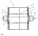
- the WO2008 / 105005 discloses a Yankee cylinder made of steel with a multi-part central shaft. This means that the two bearing journals of the Yankee are fastened to the covers separately from an internal hollow shaft, for example by means of screws (see Fig.1 ).
- This embodiment has the disadvantage that in addition a great many screws and flanges are required, which weaken the component.
- several components are to be machined, which are provided with tolerances and this can lead to an imprecise camp escape.
- the lids Due to the safety regulations for the production of pressure vessels, the lids must be welded to the shell on both sides, ie both on the inside and on the outside.
- the conventional assembly process has the disadvantage that the root welding between the second cover and the cylinder jacket in the cylinder interior is only possible through the entry through the manhole in the lid. On the one hand, this results in more difficult working conditions for the welding personnel (lack of light, air and space) and, on the other hand, a significantly higher risk of accidents.
- the aim of the invention is to disclose a steel Yankee cylinder which can be manufactured more easily.
- the central shaft is assembled before it is inserted into the steel jacket.
- the central shaft is in one piece after its production.
- the diameter of the first connecting flange is smaller than the diameter of the opening of the second end cover, so that the central shaft can be pushed through this opening in the Yankee cylinder.
- Due to the one-piece central shaft the steel shell of the Yankee cylinder can first be connected to the two end caps, preferably welded.
- the Yankee interior is easily accessible, as the two openings in the covers are quite large ( ⁇ 1500 mm), so the welding work in Yankee interior are easy to carry out. Only after connecting the end cover with the steel shell, the one-piece central shaft is inserted into the cylinder and connected thereto. Furthermore, due to the smaller number of components easier handling during assembly.
- the diameter of the first connection flange is larger than the opening of the first end cover.
- the first connecting flange is thus after the onset of the central shaft on the inside of the first end cap and can be easily connected to this, for example screwed.
- the diameter of the second connecting flange is greater than the opening of the second end cap, since, after insertion of the central shaft, the second connecting flange bears against the outer end of the second end cap and can easily be connected (for example screwed) to it.
- the central shaft thus has connecting flanges with different diameters at both ends.
- the connecting flange has a larger diameter at the driver end than the connecting flange at the drive end. Due to this special construction of the central shaft and a corresponding screwing of the central shaft with the end covers also the Possibility to exchange the central shaft non-destructively.
- the prior art does not disclose any embodiments that make it possible, for example in the case of a tightness problem, to expand the shaft without destroying the covers and thus usually also the cylinder jacket.
- the aim of the invention is also to disclose a simpler manufacturing method for a Yankee cylinder.
- the central shaft is therefore only then inserted into the cylinder when both end caps are firmly connected to the cylinder jacket. Welding to connect the jacket to the covers no longer has to be done through the manhole.
- the connecting flanges of the central shaft can either be screwed or welded to the end caps.
- a screw connection offers the possibility of easy replacement of the central shaft.
- a Yankee cylinder 11 is shown according to the prior art. It consists of a cylindrical steel shell 12, which is welded to the two end caps 13.
- the Yankee cylinder has a multi-part central shaft 14, it consists of the two bearing pins 15 and a cylindrical connecting piece 17 in the interior of the cylinder.
- the two bearing pins 15 and the connecting piece 17 are screwed to the end caps 13.
- the two bearing journals 15 are rotatably mounted in the roller bearings 16.
- the steel shell 12 is first connected to one of the two end caps 13. Thereafter, the connector 17 (hollow shaft) is inserted into the cylinder and bolted to the end cap 13.
- the second end cap 13 is placed on the steel shell 12 and welded to the cylinder jacket or screwed to the connector 17.
- the welding of the steel shell 12 with the end caps 13 must be done from the inside and the outside of the cylinder, therefore, the welding of the second end cap 13 must be performed with the steel shell 12 via a manhole in the end cap 13.
- the two bearing journals 15 are screwed to the respective end caps.
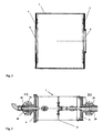
- Fig. 2 shows the cylindrical steel shell 2 according to the invention of the Yankee cylinder.
- the steel shell 2 is connected to a first end cover 3 and a second end cover 4.
- the two end covers (3, 4) each have in their center a circular opening (5, 6) for receiving the central shaft 7.
- the central shaft 7 is in Fig. 3 shown. It has a one-piece construction. By this it is meant that the central shaft 7 optionally forms, after its manufacture, a number of parts which are inserted into the steel shell 2.
- the one-piece central shaft 7 consists of the bearing pin 20, of the two connecting flanges 8 and 9 and of a central part 21. This central shaft 7 is assembled before it is inserted into the steel shell 2.
- the central shaft is rotatably supported by the bearings 10. Via the steam supply 18, steam can be supplied to the Yankee cylinder during operation. Abdampf or condensate is removed via the line 19.
- Fig. 4 the Yankee cylinder 1 is shown in the assembled state.
- the cylindrical steel shell 2 is first placed with one end on the first end cover 3 and connected thereto, for example screwed or welded. Thereafter, the second end cover 4 is connected to the other end of the cylindrical steel shell 2.
- the two end covers 3 and 4 each have the openings 5 and 6 for receiving the central shaft 7.
- the opening 5 in the first end cover 3 is slightly smaller than the opening 6 in the second end cover 4.
- the preassembled one-piece central shaft 7 is inserted through the opening 6 of the second end cover 4 in the steel shell 2.
- the diameter of the first connecting flange 8 of the central shaft 7 must be smaller than the opening 6, so that the central shaft 7 can be inserted into the cylinder.
- the diameter of the first connecting flange 8 is slightly larger than the opening 5 in the first end cap 3.
- the connecting flange 8 is after the insertion of the central shaft 7 on the inside of the first end cap 3 (see Fig. 4 ).
- the first end cover 3 can be easily screwed from the outside to the first connecting flange 8.
- the diameter of the second connecting flange 9 is slightly larger than the opening 6 of the second end cover 4. This results in the connecting flange. 9 after insertion of the central shaft 7 in the cylinder on the outside of the end cover 4 and can be screwed with this problem. This special construction also allows easy removal of the central shaft 7.
- the condensate lines 22 are mounted only after installation of the central shaft 7.
Landscapes
- Engineering & Computer Science (AREA)
- Textile Engineering (AREA)
- Mechanical Engineering (AREA)
- General Engineering & Computer Science (AREA)
- Paper (AREA)
- Drying Of Solid Materials (AREA)
Description
Den Gegenstand der Erfindung bildet ein Yankeezylinder aus Stahl für die Trocknung einer Faserstoffbahn mit einem zylindrischen Stahlmantel, der jeweils an seinen Enden mit einem ersten und einem zweiten Enddeckel verbunden ist, wobei die Enddeckel jeweils in ihrem Zentrum eine Öffnung aufweisen. Der Yankeezylinder weist eine Zentralwelle auf, die aus zwei Lagerzapfen, einem Zentralteil, einem ersten Verbindungsflansch zum Verbinden der Zentralwelle mit dem ersten Enddeckel und einem zweiten Verbindungsflansch zum Verbinden der Zentralwelle mit dem zweiten Enddeckel besteht.
Den Gegenstand der Erfindung bildet auch ein Herstellungsverfahren für den erfindungsgemäßen Yankeezylinder.The subject of the invention is a Yankee cylinder made of steel for drying a fibrous web with a cylindrical steel shell, which is connected in each case at its ends with a first and a second end cover, wherein the end cover each having an opening in its center. The Yankee cylinder has a central shaft consisting of two journal, a central part, a first connecting flange for connecting the central shaft to the first end cap and a second connecting flange for connecting the central shaft to the second end cap.
The subject matter of the invention also forms a production method for the Yankee cylinder according to the invention.
Für die Herstellung von Papierbahnen, insbesondere bei Tissue, ist es üblich, sogenannte Yankeezylinder im Trocknungsprozess einzusetzen.For the production of paper webs, in particular for tissue, it is customary to use so-called Yankee cylinders in the drying process.
Yankeezylinder haben meistens einen sehr großen Durchmesser. Sie werden mit Dampf beheizt und sind schwer herstellbar, da hohe Anforderungen in Bezug auf die internen Drücke, Dichtheit und der großen Durchmesser erfüllt werden müssen.Yankee cylinders usually have a very large diameter. They are heated by steam and are difficult to produce because of the high requirements in terms of internal pressures, tightness and large diameter.
Handelsübliche Yankeezylinder weisen beispielsweise folgende Dimensionen auf:
Diese Zylinder werden überwiegend aus Gusseisen hergestellt, aus der
Gewöhnlich besteht ein Yankeezylinder aus einer zylindrischen Mantelfläche, welche an den Enden mit unterschiedlich geformten Enddeckeln verschlossen wird. Die beiden Deckel können dabei mit dem Zylindermantel verschraubt oder auch verschweißt werden.These cylinders are mainly made of cast iron, from the
Usually, a Yankee cylinder consists of a cylindrical shell surface, which is closed at the ends with differently shaped end caps. The two covers can be bolted to the cylinder jacket or welded.
Ein Yankeezylinder wird über Zapfen drehbar gelagert und weist in seinem Inneren eine Hohlwelle oder Achse auf, durch die Dampf zur Beheizung in den Zylinder eingebracht wird bzw. Abdampf und Kondensat abgeführt werden kann.A Yankee cylinder is rotatably supported by pins and has in its interior a hollow shaft or axis through which steam is introduced for heating in the cylinder or exhaust steam and condensate can be removed.
Die
Zusätzlich sind mehrere Bauteile zu bearbeiten, die mit Toleranzen versehen sind und dadurch kann es zu einer unpräziseren Lagerflucht kommen.The
In addition, several components are to be machined, which are provided with tolerances and this can lead to an imprecise camp escape.
Herkömmliche Yankeezylinder wie sie in der
- 1. Der Zylindermantel wird auf den ersten Deckel aufgesetzt und mit diesem verbunden (verschraubt oder verschweißt);
- 2. Die Hohlwelle wird mit den darauf befestigten Dampf und Kondensatleitungen in den Zylinder eingesetzt;
- 3. Die Hohlwelle wird mit dem ersten Deckel verschweißt oder verschraubt;
- 4. Der zweite Deckel wird auf den Zylindermantel aufgesetzt und mit dem Zylindermantel und mit der Hohlwelle verbunden;
- 5. Die Lagerzapfen werden an den Deckeln befestigt;
- 1. The cylinder jacket is placed on the first cover and connected to this (screwed or welded);
- 2. The hollow shaft is inserted with the steam and condensate lines attached to it in the cylinder;
- 3. The hollow shaft is welded or screwed to the first cover;
- 4. The second cover is placed on the cylinder jacket and connected to the cylinder jacket and with the hollow shaft;
- 5. The journals are attached to the lids;
Durch die Sicherheitsvorschriften für die Fertigung von Druckbehältern müssen die Deckel mit dem Mantel beidseitig verschweißt werden, also sowohl an der Innenseite als auch an der Außenseite. Der herkömmliche Montageablauf weist den Nachteil auf, dass die Wurzelverschweißung zwischen dem zweiten Deckel und dem Zylindermantel im Zylinderinneren nur durch den Einstieg über das Mannloch im Deckel möglich ist. Dadurch ergeben sich für das Schweißpersonal einerseits erschwerte Arbeitsbedingungen (Licht-, Luft- und Platzmangel) und andererseits ist dadurch eine wesentlich höhere Unfallgefahr gegeben.Due to the safety regulations for the production of pressure vessels, the lids must be welded to the shell on both sides, ie both on the inside and on the outside. The conventional assembly process has the disadvantage that the root welding between the second cover and the cylinder jacket in the cylinder interior is only possible through the entry through the manhole in the lid. On the one hand, this results in more difficult working conditions for the welding personnel (lack of light, air and space) and, on the other hand, a significantly higher risk of accidents.
Ziel der Erfindung ist es, einen Yankeezylinder aus Stahl zu offenbaren, der einfacher hergestellt werden kann.The aim of the invention is to disclose a steel Yankee cylinder which can be manufactured more easily.
Erfindungsgemäß wird die Zentralwelle zusammengebaut bevor sie in den Stahlmantel eingesetzt wird. Die Zentralwelle ist nach ihrer Fertigung einteilig. Der Durchmesser des ersten Verbindungsflansches ist geringer als der Durchmesser der Öffnung des zweiten Enddeckels, sodass die Zentralwelle durch diese Öffnung in den Yankeezylinder geschoben werden kann.
Durch die einteilige Zentralwelle kann der Stahlmantel des Yankeezylinders zuerst mit den beiden Enddeckeln verbunden werden, vorzugsweise verschweißt werden. Das Yankeeinnere ist dabei leicht zugänglich, da die beiden Öffnungen in den Deckeln recht groß sind (~ 1500 mm), somit sind die Schweißarbeiten im Yankeeinneren leicht durchführbar.
Erst nach dem Verbinden der Enddeckel mit dem Stahlmantel wird die einteilige Zentralwelle in den Zylinder eingesetzt und mit diesem verbunden. Des Weiteren ergibt sich aufgrund der geringeren Bauteileanzahl ein einfacheres Handling bei der Montage.According to the invention, the central shaft is assembled before it is inserted into the steel jacket. The central shaft is in one piece after its production. The diameter of the first connecting flange is smaller than the diameter of the opening of the second end cover, so that the central shaft can be pushed through this opening in the Yankee cylinder.
Due to the one-piece central shaft, the steel shell of the Yankee cylinder can first be connected to the two end caps, preferably welded. The Yankee interior is easily accessible, as the two openings in the covers are quite large (~ 1500 mm), so the welding work in Yankee interior are easy to carry out.
Only after connecting the end cover with the steel shell, the one-piece central shaft is inserted into the cylinder and connected thereto. Furthermore, due to the smaller number of components easier handling during assembly.
Vorteilhafterweise ist der Durchmesser des ersten Verbindungsflansches größer als die Öffnung des ersten Enddeckels. Der erste Verbindungsflansch liegt somit nach dem Einsetzen der Zentralwelle an der Innenseite des ersten Enddeckels an und kann mit diesem leicht verbunden, beispielsweise verschraubt werden.Advantageously, the diameter of the first connection flange is larger than the opening of the first end cover. The first connecting flange is thus after the onset of the central shaft on the inside of the first end cap and can be easily connected to this, for example screwed.
Es ist auch günstig, wenn der Durchmesser des zweiten Verbindungsflansches größer ist, als die Öffnung des zweiten Enddeckels, da dadurch nach dem Einsetzen der Zentralwelle der zweite Verbindungsflansch an der Außenseite des zweiten Enddeckels anliegt und leicht mit diesem verbunden (z.B. verschraubt) werden kann.It is also favorable if the diameter of the second connecting flange is greater than the opening of the second end cap, since, after insertion of the central shaft, the second connecting flange bears against the outer end of the second end cap and can easily be connected (for example screwed) to it.
Die Zentralwelle hat also an beiden Enden Verbindungsflansche mit unterschiedlichem Durchmesser. Vorteilhafterweise hat der Verbindungsflansch am führerseitigen Ende einen größeren Durchmesser als der Verbindungsflansch am triebseitigen Ende. Durch diesen speziellen Aufbau der Zentralwelle und bei einer entsprechenden Verschraubung der Zentralwelle mit den Enddeckeln wird auch die Möglichkeit geschaffen, die Zentralwelle zerstörungsfrei auszutauschen. Der bisherige Stand der Technik offenbart keine Ausführungsformen, die es ermöglichen, zum Beispiel im Falle eines Dichtheitsproblems, die Welle auszubauen, ohne dabei die Deckel und damit meist auch den Zylindermantel zu zerstören.The central shaft thus has connecting flanges with different diameters at both ends. Advantageously, the connecting flange has a larger diameter at the driver end than the connecting flange at the drive end. Due to this special construction of the central shaft and a corresponding screwing of the central shaft with the end covers also the Possibility to exchange the central shaft non-destructively. The prior art does not disclose any embodiments that make it possible, for example in the case of a tightness problem, to expand the shaft without destroying the covers and thus usually also the cylinder jacket.
Ziel der Erfindung ist es auch, ein einfacheres Herstellungsverfahren für einen Yankeezylinder zu offenbaren.The aim of the invention is also to disclose a simpler manufacturing method for a Yankee cylinder.
Das erfindungsgsmäße Fertigungsverfahren eines Yankeezylinders aus Stahl umfasst dabei folgende Schritte:
- 1.) Ein zylindrischer Stahlmantel wird mit einem Ende auf einen ersten, in seinem Zentrum eine Öffnung aufweisenden Enddeckel aufgesetzt und mit diesem verbunden, insbesondere verschweißt;
- 2.) Ein zweiter, in seinem Zentrum eine Öffnung aufweisender Enddeckel wird mit dem anderen Ende des zylindrischen Stahlmantels verbunden, insbesondere verschweißt;
- 3.) Eine aus zwei Lagerzapfen, einem Zentralteil, einem ersten Verbindungsflansch und einem zweiten Verbindungsflansch bestehende Zentralwelle wird zusammengebaut, sodass sie nach ihrer Fertigung einteilig ist, wobei der Durchmesser des ersten Verbindungsflansches geringer ist als der Durchmesser der Öffnung des zweiten Enddeckels;
- 4.) Die einteilige Zentralwelle wird durch die Öffnung im zweiten Enddeckel in das Zylinderinnere eingeführt bzw. eingesetzt;
- 5.) Der erste Verbindungsflansch wird mit dem ersten Enddeckel und der zweite Verbindungsflansch mit dem zweiten Enddeckel verbunden.
- 1.) A cylindrical steel jacket is placed with one end on a first, in its center an opening end cap and connected thereto, in particular welded;
- 2.) A second, in its center an opening end having end cap is connected to the other end of the cylindrical steel shell, in particular welded;
- 3.) A central shaft consisting of two trunnions, a central part, a first connecting flange and a second connecting flange is assembled so that it is integral after its manufacture, the diameter of the first connecting flange being smaller than the diameter of the opening of the second end cover;
- 4.) The one-piece central shaft is inserted or inserted through the opening in the second end cap into the cylinder interior;
- 5.) The first connecting flange is connected to the first end cap and the second connecting flange to the second end cap.
Die Zentralwelle wird also erst dann in den Zylinder eingesetzt, wenn beide Enddeckel fest mit dem Zylindermantel verbunden sind. Schweißarbeiten zur Verbindung des Mantels mit den Deckeln müssen nicht mehr über das Mannloch ausgeführt werden.The central shaft is therefore only then inserted into the cylinder when both end caps are firmly connected to the cylinder jacket. Welding to connect the jacket to the covers no longer has to be done through the manhole.
Im Wesentlichen müssen nur die beiden fertig bearbeiteten Bauteile Zentralwelle und Zylinder mit Enddeckel zusammengebaut werden. Dies reduziert auch die Fehlermöglichkeiten bei der Montage im Vergleich zu Trockenzylindern die aus mehreren Bauteilen bestehen.Essentially, only the two finished components central shaft and cylinder with end cover have to be assembled. This also reduces the Possible errors during assembly in comparison to drying cylinders which consist of several components.
Die Verbindungsflansche der Zentralwelle können entweder mit den Enddeckeln verschraubt oder verschweißt werden. Eine Verschraubung bietet die Möglichkeit einer einfachen Austauschbarkeit der Zentralwelle.The connecting flanges of the central shaft can either be screwed or welded to the end caps. A screw connection offers the possibility of easy replacement of the central shaft.
Im Folgenden wird die Erfindung anhand von Zeichnungen beschrieben.
Es zeigt:
-
Fig. 1 einen Yankeezylinder aus Stahl nach dem Stand der Technik, wie er in derWO 2008/105005 -
Fig. 2 den erfindungsgemäßen Zylindermantel mit den beiden Enddeckeln; -
Fig. 3 die erfindungsgemäße einteilige Zentralwelle, die in den Zylindermantel gemäßFig. 2 eingesetzt wird; -
Fig. 4 den erfindungsgemäßen zusammengebauten Yankeezylinder;
It shows:
-
Fig. 1 a Yankee cylinder made of steel according to the prior art, as in theWO 2008/105005 -
Fig. 2 the cylinder jacket according to the invention with the two end caps; -
Fig. 3 the one-piece central shaft according to the invention, in the cylinder jacket according toFig. 2 is used; -
Fig. 4 the assembled Yankee cylinder according to the invention;
In
Bei der Herstellung dieses Yankeezylinders 11 wird zuerst der Stahlmantel 12 mit einem der beiden Enddeckel 13 verbunden. Danach wird das Verbindungsstück 17 (Hohlwelle) in den Zylinder eingesetzt und mit dem Enddeckel 13 verschraubt. Danach wird der zweite Enddeckel 13 auf den Stahlmantel 12 aufgesetzt und mit dem Zylindermantel verschweißt bzw. mit dem Verbindungsstück 17 verschraubt. Die Verschweißung des Stahlmantels 12 mit den Enddeckeln 13 muss von der Innenseite und der Außenseite des Zylinders erfolgen, daher muss die Verschweißung des zweiten Enddeckels 13 mit dem Stahlmantel 12 über ein Mannloch im Enddeckel 13 durchgeführt werden. Im Anschluss daran werden die beiden Lagerzapfen 15 mit den jeweiligen Enddeckeln verschraubt.In
In the production of this
Die Zentralwelle 7 ist in
In
In einem weiteren Montageschritt wird die vormontierte einteilige Zentralwelle 7 durch die Öffnung 6 des zweiten Enddeckels 4 in den Stahlmantel 2 eingesetzt.
Der Durchmesser des ersten Verbindungsflansches 8 der Zentralwelle 7 muss dabei kleiner als die Öffnung 6 sein, damit die Zentralwelle 7 in den Zylinder eingesetzt werden kann.In a further assembly step, the preassembled one-piece central shaft 7 is inserted through the
The diameter of the first connecting
Im vorliegenden Beispiel ist der Durchmesser des ersten Verbindungsflansches 8 etwas größer als die Öffnung 5 im ersten Enddeckel 3. Dadurch liegt der Verbindungsflansch 8 nach dem Einsetzten der Zentralwelle 7 an der Innenseite des ersten Enddeckels 3 an (siehe
Ebenso ist der Durchmesser des zweiten Verbindungsflansches 9 etwas größer als die Öffnung 6 des zweiten Enddeckels 4. Dadurch liegt der Verbindungsflansch 9 nach dem Einsetzen der Zentralwelle 7 in den Zylinder an der Außenseite des Enddeckels 4 an und kann so mit diesem problemlos verschraubt werden. Dieser spezielle Aufbau ermöglicht auch einen einfachen Ausbau der Zentralwelle 7.
Die Kondensatleitungen 22 werden erst nach dem Einbau der Zentralwelle 7 montiert.Likewise, the diameter of the second connecting
The condensate lines 22 are mounted only after installation of the central shaft 7.
Claims (7)
- Yankee dryer (1) made of steel, with a cylindrical steel (2) shell that is connected to a first and second cylinder end cover (3, 4) at either end, where the end covers (3, 4) each have an opening (5, 6) at their centre and where the Yankee dryer (1) has a central shaft (7) consisting of two bearing journals (20), a central part (21), a first connecting flange (8) for connecting the central shaft (7) to the first end cover (3) and a second connecting flange (9) for connecting the central shaft (7) to the second end cover (4), characterised by the central shaft (7) being assembled before being inserted into the steel shell (2) and being a one-piece component after manufacture, and by the diameter of the first connecting flange (8) being smaller than the diameter of the opening (6) in the second end cover (4) so that the central shaft (7) can be pushed through this opening (6) into the Yankee cylinder (1).
- Yankee dryer (1) according to Claim 1, characterised by the diameter of the first connecting flange (8) being larger than the opening (5) in the first end cover (3).
- Yankee dryer (1) according to Claim 1 or 2, characterised by the diameter of the second connecting flange (9) being larger than the opening (6) in the second end cover (4).
- Yankee dryer (1) according to one of Claims 1 to 3, characterised by the connecting flanges (8, 9) of the central shaft (7) being bolted to the end covers (3, 4).
- Processes for manufacturing a Yankee dryer (1) made of steel comprise the following steps:a) One end of a cylindrical steel shell (2) is placed on a first end cover (3) with an opening (5) in its centre and joined to it, particularly welded;b) A second end cover (4) with an opening (6) in its centre is joined to the other end of the cylindrical steel shell (2), particularly welded;c) A central shaft (7) comprising two bearing journals (20), a central part (21), a first connecting flange (8) and a second connecting flange (9) is assembled to form a one-piece component after manufacture, where the diameter of the first connecting flange (8) is smaller than the diameter of the opening (6) in the second end cover (4);d) The one-piece central shaft (7) is inserted into the inside of the cylinder through the opening (6) in the second end cover (4);e) The first connecting flange (8) is joined to the first end cover (3) and the second connecting flange (9) is joined to the second end cover (4).
- Process according to Claim 5, characterised by the connecting flanges (8, 9) being bolted to the end covers (3, 4).
- Process according to Claim 5, characterised by the connecting flanges being welded to the end covers.
Priority Applications (1)
| Application Number | Priority Date | Filing Date | Title |
|---|---|---|---|
| PL11002527T PL2385171T3 (en) | 2010-05-06 | 2011-03-28 | Yankee cylinder for drying a sheet of fibrous material |
Applications Claiming Priority (1)
| Application Number | Priority Date | Filing Date | Title |
|---|---|---|---|
| AT0076310A AT509053B1 (en) | 2010-05-06 | 2010-05-06 | YANKEY CYLINDER FOR DRYING A FIBROUS RAIL |
Publications (2)
| Publication Number | Publication Date |
|---|---|
| EP2385171A1 EP2385171A1 (en) | 2011-11-09 |
| EP2385171B1 true EP2385171B1 (en) | 2012-09-19 |
Family
ID=43919790
Family Applications (1)
| Application Number | Title | Priority Date | Filing Date |
|---|---|---|---|
| EP11002527A Active EP2385171B1 (en) | 2010-05-06 | 2011-03-28 | Yankee cylinder for drying a sheet of fibrous material |
Country Status (6)
| Country | Link |
|---|---|
| US (1) | US8919008B2 (en) |
| EP (1) | EP2385171B1 (en) |
| CN (1) | CN102234953B (en) |
| AT (1) | AT509053B1 (en) |
| CA (1) | CA2737692C (en) |
| PL (1) | PL2385171T3 (en) |
Cited By (1)
| Publication number | Priority date | Publication date | Assignee | Title |
|---|---|---|---|---|
| WO2015000648A1 (en) | 2013-07-05 | 2015-01-08 | Voith Patent Gmbh | Large cylinder drying roller and method for producing a large cylinder drying roller |
Families Citing this family (10)
| Publication number | Priority date | Publication date | Assignee | Title |
|---|---|---|---|---|
| SE1251287A1 (en) * | 2012-11-13 | 2014-05-06 | Valmet Aktiebolag | Yankee cylinder made of steel |
| WO2015014515A1 (en) * | 2013-08-01 | 2015-02-05 | Voith Patent Gmbh | Large-cylinder drying drum and method for producing a large-cylinder drying drum |
| CN105463921A (en) * | 2015-03-24 | 2016-04-06 | 溧阳市江南烘缸制造有限公司 | Steel yankee drying cylinder |
| CN104792149A (en) * | 2015-04-27 | 2015-07-22 | 江苏华东造纸机械有限公司 | Industrial steel welding heating drying cylinder |
| CN105200839A (en) * | 2015-10-12 | 2015-12-30 | 白城福佳科技有限公司 | Paper machine and drying cylinder thereof |
| SE540216C2 (en) * | 2016-03-31 | 2018-05-02 | Valmet Oy | A yankee drying cylinder for drying a fibrous web and a method of making a yankee drying cylinder |
| US10533283B2 (en) * | 2017-07-18 | 2020-01-14 | Valmet, Inc. | Reduced diameter foraminous exhaust cylinder |
| DE102018119489A1 (en) | 2018-08-10 | 2019-06-27 | Voith Patent Gmbh | drying roll |
| CN112665343B (en) * | 2020-12-25 | 2022-10-28 | 平江县绿宝堂中药材发展有限公司 | Be used for chinese-medicinal material matrimony vine drying device |
| CN113427219B (en) * | 2021-07-19 | 2023-07-14 | 溧阳市江南烘缸制造有限公司 | Manufacturing method of large steel Yankee dryer |
Family Cites Families (16)
| Publication number | Priority date | Publication date | Assignee | Title |
|---|---|---|---|---|
| GB685009A (en) * | 1949-10-31 | 1952-12-31 | Voith Gmbh J M | Improvements in and relating to drying cylinders, more particularly for paper making machines |
| US3022047A (en) * | 1957-11-04 | 1962-02-20 | Swaney Robert Casper | Stabil-heat drier |
| US3633662A (en) * | 1970-01-16 | 1972-01-11 | Beloit Corp | Dryer drum assembly |
| US3919783A (en) * | 1971-03-29 | 1975-11-18 | Anthony J Cirrito | Method for hot gas heat transfer, particularly for paper drying |
| US3808700A (en) * | 1972-12-26 | 1974-05-07 | Kimberly Clark Co | Rotary drying drum |
| US4196689A (en) | 1977-01-17 | 1980-04-08 | J. M. Voith Gmbh | Apparatus for drying paper webs or the like |
| DE2707923A1 (en) | 1977-02-24 | 1978-08-31 | Voith Gmbh J M | Paper web drying cylinder - stainless steel sleeve welded to carbon steel end cover by carbon steel end ring and having thickness compatible with sleeve and cover |
| AT383837B (en) * | 1982-05-26 | 1987-08-25 | Voith Gmbh J M | DRY CYLINDERS FOR PAPER MACHINES |
| FI960702A0 (en) * | 1996-02-16 | 1996-02-16 | Ppr Consulting Ltd Oy | Torkanordning Foer fiberbanor |
| CN2283669Y (en) * | 1996-09-25 | 1998-06-10 | 程永智 | Inlet head device of dryer |
| US6683284B2 (en) * | 2002-03-22 | 2004-01-27 | Metso Paper Karlstad Ab | Thermal roll for papermaking with a fluid circulation system and method therefor |
| DE10252110A1 (en) * | 2002-11-08 | 2004-05-27 | Siemens Ag | Direct drive for a cylinder, to process paper and other web materials, has a drive housing around the hollow cylinder shaft with a keyed rotor and a stator fixed to the drive housing |
| DE102006020242A1 (en) * | 2006-04-27 | 2007-10-31 | Voith Patent Gmbh | Roller drive end and method for mounting the same |
| DE202007019227U1 (en) * | 2007-03-01 | 2011-05-05 | Toscotec S.R.L. | Yankee cylinder for a papermaking machine |
| CN201265122Y (en) * | 2008-05-30 | 2009-07-01 | 焦作市崇义轻工机械有限公司 | Cast iron drying cylinder end cover for paper making machine |
| IT1395588B1 (en) * | 2009-09-09 | 2012-10-16 | Toscotec S P A | "INSULATED MONOLUCID CYLINDER" |
-
2010
- 2010-05-06 AT AT0076310A patent/AT509053B1/en active
-
2011
- 2011-03-28 PL PL11002527T patent/PL2385171T3/en unknown
- 2011-03-28 EP EP11002527A patent/EP2385171B1/en active Active
- 2011-04-20 CA CA2737692A patent/CA2737692C/en active Active
- 2011-04-27 CN CN201110123431.3A patent/CN102234953B/en active Active
- 2011-05-06 US US13/068,246 patent/US8919008B2/en active Active
Cited By (1)
| Publication number | Priority date | Publication date | Assignee | Title |
|---|---|---|---|---|
| WO2015000648A1 (en) | 2013-07-05 | 2015-01-08 | Voith Patent Gmbh | Large cylinder drying roller and method for producing a large cylinder drying roller |
Also Published As
| Publication number | Publication date |
|---|---|
| AT509053A4 (en) | 2011-06-15 |
| CN102234953A (en) | 2011-11-09 |
| PL2385171T3 (en) | 2013-02-28 |
| US20140068961A1 (en) | 2014-03-13 |
| US8919008B2 (en) | 2014-12-30 |
| CN102234953B (en) | 2016-03-30 |
| CA2737692A1 (en) | 2011-11-06 |
| AT509053B1 (en) | 2011-06-15 |
| CA2737692C (en) | 2017-04-18 |
| EP2385171A1 (en) | 2011-11-09 |
Similar Documents
| Publication | Publication Date | Title |
|---|---|---|
| EP2385171B1 (en) | Yankee cylinder for drying a sheet of fibrous material | |
| EP3196356B1 (en) | Drying roller | |
| DE202007019227U1 (en) | Yankee cylinder for a papermaking machine | |
| AT511232B1 (en) | METHOD FOR PRODUCING A YANKEE CYLINDER | |
| EP3017111B1 (en) | Large drying cylinder and method for producing a large drying cylinder | |
| DE69820883T2 (en) | ROLLED BEARING RING AND METHOD FOR THE PRODUCTION THEREOF | |
| DE102007004212A1 (en) | Longitudinal shaft arrangement with stiffening ring and seal | |
| AT11146U1 (en) | YANKEY CYLINDER FOR A MACHINE FOR PAPER MANUFACTURE | |
| DE69823972T2 (en) | Apparatus for mechanically treating paper, the apparatus comprising an improved bearing for a roll, and methods of replacing the rolls in this apparatus | |
| DE102009037274A1 (en) | Roller and a roll stand for rolling rolling | |
| WO2015014515A1 (en) | Large-cylinder drying drum and method for producing a large-cylinder drying drum | |
| DE69908183T2 (en) | DAMPING SYSTEM FOR ROLLING CARDBOARD MACHINES | |
| EP3290552A1 (en) | Godet roller | |
| DE102012012293B4 (en) | Device for forming a workpiece | |
| DE212017000093U1 (en) | Yankee drying cylinder for drying a fibrous web | |
| DE102006020242A1 (en) | Roller drive end and method for mounting the same | |
| AT510755B1 (en) | CONNECTION ARRANGEMENT | |
| DE102015200896A1 (en) | drying cylinders | |
| DE102018119489A1 (en) | drying roll | |
| DE102022209083B4 (en) | Door drive and manufacturing process | |
| DE102019209120B3 (en) | Drive for a wing of a door or a window and manufacturing process for such | |
| WO2011045237A1 (en) | End face cover | |
| DE102020130222A1 (en) | Process and device for the production of at least partially profiled tubular components | |
| DE102008002112A1 (en) | deflection roll | |
| DE102014017299A1 (en) | Crank drive for a reciprocating internal combustion engine of a motor vehicle |
Legal Events
| Date | Code | Title | Description |
|---|---|---|---|
| AK | Designated contracting states |
Kind code of ref document: A1 Designated state(s): AL AT BE BG CH CY CZ DE DK EE ES FI FR GB GR HR HU IE IS IT LI LT LU LV MC MK MT NL NO PL PT RO RS SE SI SK SM TR |
|
| AX | Request for extension of the european patent |
Extension state: BA ME |
|
| PUAI | Public reference made under article 153(3) epc to a published international application that has entered the european phase |
Free format text: ORIGINAL CODE: 0009012 |
|
| 17P | Request for examination filed |
Effective date: 20120314 |
|
| GRAP | Despatch of communication of intention to grant a patent |
Free format text: ORIGINAL CODE: EPIDOSNIGR1 |
|
| RIC1 | Information provided on ipc code assigned before grant |
Ipc: D21F 5/02 20060101AFI20120509BHEP |
|
| GRAS | Grant fee paid |
Free format text: ORIGINAL CODE: EPIDOSNIGR3 |
|
| GRAA | (expected) grant |
Free format text: ORIGINAL CODE: 0009210 |
|
| AK | Designated contracting states |
Kind code of ref document: B1 Designated state(s): AL AT BE BG CH CY CZ DE DK EE ES FI FR GB GR HR HU IE IS IT LI LT LU LV MC MK MT NL NO PL PT RO RS SE SI SK SM TR |
|
| REG | Reference to a national code |
Ref country code: GB Ref legal event code: FG4D Free format text: NOT ENGLISH |
|
| REG | Reference to a national code |
Ref country code: CH Ref legal event code: EP |
|
| REG | Reference to a national code |
Ref country code: IE Ref legal event code: FG4D Free format text: LANGUAGE OF EP DOCUMENT: GERMAN |
|
| REG | Reference to a national code |
Ref country code: AT Ref legal event code: REF Ref document number: 576111 Country of ref document: AT Kind code of ref document: T Effective date: 20121015 |
|
| REG | Reference to a national code |
Ref country code: DE Ref legal event code: R096 Ref document number: 502011000098 Country of ref document: DE Effective date: 20121108 |
|
| REG | Reference to a national code |
Ref country code: SE Ref legal event code: TRGR |
|
| PG25 | Lapsed in a contracting state [announced via postgrant information from national office to epo] |
Ref country code: NO Free format text: LAPSE BECAUSE OF FAILURE TO SUBMIT A TRANSLATION OF THE DESCRIPTION OR TO PAY THE FEE WITHIN THE PRESCRIBED TIME-LIMIT Effective date: 20121219 Ref country code: LT Free format text: LAPSE BECAUSE OF FAILURE TO SUBMIT A TRANSLATION OF THE DESCRIPTION OR TO PAY THE FEE WITHIN THE PRESCRIBED TIME-LIMIT Effective date: 20120919 Ref country code: HR Free format text: LAPSE BECAUSE OF FAILURE TO SUBMIT A TRANSLATION OF THE DESCRIPTION OR TO PAY THE FEE WITHIN THE PRESCRIBED TIME-LIMIT Effective date: 20120919 |
|
| REG | Reference to a national code |
Ref country code: NL Ref legal event code: VDEP Effective date: 20120919 |
|
| REG | Reference to a national code |
Ref country code: LT Ref legal event code: MG4D Effective date: 20120919 |
|
| PG25 | Lapsed in a contracting state [announced via postgrant information from national office to epo] |
Ref country code: SI Free format text: LAPSE BECAUSE OF FAILURE TO SUBMIT A TRANSLATION OF THE DESCRIPTION OR TO PAY THE FEE WITHIN THE PRESCRIBED TIME-LIMIT Effective date: 20120919 Ref country code: LV Free format text: LAPSE BECAUSE OF FAILURE TO SUBMIT A TRANSLATION OF THE DESCRIPTION OR TO PAY THE FEE WITHIN THE PRESCRIBED TIME-LIMIT Effective date: 20120919 Ref country code: GR Free format text: LAPSE BECAUSE OF FAILURE TO SUBMIT A TRANSLATION OF THE DESCRIPTION OR TO PAY THE FEE WITHIN THE PRESCRIBED TIME-LIMIT Effective date: 20121220 |
|
| REG | Reference to a national code |
Ref country code: PL Ref legal event code: T3 |
|
| PG25 | Lapsed in a contracting state [announced via postgrant information from national office to epo] |
Ref country code: IS Free format text: LAPSE BECAUSE OF FAILURE TO SUBMIT A TRANSLATION OF THE DESCRIPTION OR TO PAY THE FEE WITHIN THE PRESCRIBED TIME-LIMIT Effective date: 20130119 Ref country code: CZ Free format text: LAPSE BECAUSE OF FAILURE TO SUBMIT A TRANSLATION OF THE DESCRIPTION OR TO PAY THE FEE WITHIN THE PRESCRIBED TIME-LIMIT Effective date: 20120919 Ref country code: RO Free format text: LAPSE BECAUSE OF FAILURE TO SUBMIT A TRANSLATION OF THE DESCRIPTION OR TO PAY THE FEE WITHIN THE PRESCRIBED TIME-LIMIT Effective date: 20120919 Ref country code: EE Free format text: LAPSE BECAUSE OF FAILURE TO SUBMIT A TRANSLATION OF THE DESCRIPTION OR TO PAY THE FEE WITHIN THE PRESCRIBED TIME-LIMIT Effective date: 20120919 Ref country code: NL Free format text: LAPSE BECAUSE OF FAILURE TO SUBMIT A TRANSLATION OF THE DESCRIPTION OR TO PAY THE FEE WITHIN THE PRESCRIBED TIME-LIMIT Effective date: 20120919 |
|
| PG25 | Lapsed in a contracting state [announced via postgrant information from national office to epo] |
Ref country code: PT Free format text: LAPSE BECAUSE OF FAILURE TO SUBMIT A TRANSLATION OF THE DESCRIPTION OR TO PAY THE FEE WITHIN THE PRESCRIBED TIME-LIMIT Effective date: 20130121 Ref country code: SK Free format text: LAPSE BECAUSE OF FAILURE TO SUBMIT A TRANSLATION OF THE DESCRIPTION OR TO PAY THE FEE WITHIN THE PRESCRIBED TIME-LIMIT Effective date: 20120919 |
|
| PLBE | No opposition filed within time limit |
Free format text: ORIGINAL CODE: 0009261 |
|
| STAA | Information on the status of an ep patent application or granted ep patent |
Free format text: STATUS: NO OPPOSITION FILED WITHIN TIME LIMIT |
|
| PG25 | Lapsed in a contracting state [announced via postgrant information from national office to epo] |
Ref country code: RS Free format text: LAPSE BECAUSE OF FAILURE TO SUBMIT A TRANSLATION OF THE DESCRIPTION OR TO PAY THE FEE WITHIN THE PRESCRIBED TIME-LIMIT Effective date: 20120919 Ref country code: DK Free format text: LAPSE BECAUSE OF FAILURE TO SUBMIT A TRANSLATION OF THE DESCRIPTION OR TO PAY THE FEE WITHIN THE PRESCRIBED TIME-LIMIT Effective date: 20120919 Ref country code: BG Free format text: LAPSE BECAUSE OF FAILURE TO SUBMIT A TRANSLATION OF THE DESCRIPTION OR TO PAY THE FEE WITHIN THE PRESCRIBED TIME-LIMIT Effective date: 20121219 |
|
| 26N | No opposition filed |
Effective date: 20130620 |
|
| REG | Reference to a national code |
Ref country code: HU Ref legal event code: AG4A Ref document number: E016264 Country of ref document: HU |
|
| BERE | Be: lapsed |
Owner name: ANDRITZ AG Effective date: 20130331 |
|
| REG | Reference to a national code |
Ref country code: DE Ref legal event code: R097 Ref document number: 502011000098 Country of ref document: DE Effective date: 20130620 |
|
| PG25 | Lapsed in a contracting state [announced via postgrant information from national office to epo] |
Ref country code: MC Free format text: LAPSE BECAUSE OF NON-PAYMENT OF DUE FEES Effective date: 20130331 Ref country code: ES Free format text: LAPSE BECAUSE OF FAILURE TO SUBMIT A TRANSLATION OF THE DESCRIPTION OR TO PAY THE FEE WITHIN THE PRESCRIBED TIME-LIMIT Effective date: 20121230 |
|
| PG25 | Lapsed in a contracting state [announced via postgrant information from national office to epo] |
Ref country code: CY Free format text: LAPSE BECAUSE OF FAILURE TO SUBMIT A TRANSLATION OF THE DESCRIPTION OR TO PAY THE FEE WITHIN THE PRESCRIBED TIME-LIMIT Effective date: 20120919 |
|
| REG | Reference to a national code |
Ref country code: FR Ref legal event code: ST Effective date: 20131129 |
|
| REG | Reference to a national code |
Ref country code: IE Ref legal event code: MM4A |
|
| PG25 | Lapsed in a contracting state [announced via postgrant information from national office to epo] |
Ref country code: AL Free format text: LAPSE BECAUSE OF FAILURE TO SUBMIT A TRANSLATION OF THE DESCRIPTION OR TO PAY THE FEE WITHIN THE PRESCRIBED TIME-LIMIT Effective date: 20120919 Ref country code: IE Free format text: LAPSE BECAUSE OF NON-PAYMENT OF DUE FEES Effective date: 20130328 Ref country code: BE Free format text: LAPSE BECAUSE OF NON-PAYMENT OF DUE FEES Effective date: 20130331 Ref country code: FR Free format text: LAPSE BECAUSE OF NON-PAYMENT OF DUE FEES Effective date: 20130402 |
|
| PG25 | Lapsed in a contracting state [announced via postgrant information from national office to epo] |
Ref country code: MT Free format text: LAPSE BECAUSE OF FAILURE TO SUBMIT A TRANSLATION OF THE DESCRIPTION OR TO PAY THE FEE WITHIN THE PRESCRIBED TIME-LIMIT Effective date: 20120919 |
|
| REG | Reference to a national code |
Ref country code: CH Ref legal event code: PL |
|
| PG25 | Lapsed in a contracting state [announced via postgrant information from national office to epo] |
Ref country code: LI Free format text: LAPSE BECAUSE OF NON-PAYMENT OF DUE FEES Effective date: 20140331 Ref country code: CH Free format text: LAPSE BECAUSE OF NON-PAYMENT OF DUE FEES Effective date: 20140331 |
|
| PG25 | Lapsed in a contracting state [announced via postgrant information from national office to epo] |
Ref country code: SM Free format text: LAPSE BECAUSE OF FAILURE TO SUBMIT A TRANSLATION OF THE DESCRIPTION OR TO PAY THE FEE WITHIN THE PRESCRIBED TIME-LIMIT Effective date: 20120919 |
|
| PG25 | Lapsed in a contracting state [announced via postgrant information from national office to epo] |
Ref country code: TR Free format text: LAPSE BECAUSE OF FAILURE TO SUBMIT A TRANSLATION OF THE DESCRIPTION OR TO PAY THE FEE WITHIN THE PRESCRIBED TIME-LIMIT Effective date: 20120919 |
|
| PG25 | Lapsed in a contracting state [announced via postgrant information from national office to epo] |
Ref country code: MK Free format text: LAPSE BECAUSE OF FAILURE TO SUBMIT A TRANSLATION OF THE DESCRIPTION OR TO PAY THE FEE WITHIN THE PRESCRIBED TIME-LIMIT Effective date: 20120919 Ref country code: LU Free format text: LAPSE BECAUSE OF NON-PAYMENT OF DUE FEES Effective date: 20130328 |
|
| GBPC | Gb: european patent ceased through non-payment of renewal fee |
Effective date: 20150328 |
|
| PG25 | Lapsed in a contracting state [announced via postgrant information from national office to epo] |
Ref country code: GB Free format text: LAPSE BECAUSE OF NON-PAYMENT OF DUE FEES Effective date: 20150328 |
|
| REG | Reference to a national code |
Ref country code: AT Ref legal event code: MM01 Ref document number: 576111 Country of ref document: AT Kind code of ref document: T Effective date: 20160328 |
|
| PG25 | Lapsed in a contracting state [announced via postgrant information from national office to epo] |
Ref country code: AT Free format text: LAPSE BECAUSE OF NON-PAYMENT OF DUE FEES Effective date: 20160328 |
|
| PGFP | Annual fee paid to national office [announced via postgrant information from national office to epo] |
Ref country code: HU Payment date: 20240322 Year of fee payment: 14 Ref country code: FI Payment date: 20240320 Year of fee payment: 14 Ref country code: DE Payment date: 20240320 Year of fee payment: 14 |
|
| PGFP | Annual fee paid to national office [announced via postgrant information from national office to epo] |
Ref country code: SE Payment date: 20240320 Year of fee payment: 14 Ref country code: PL Payment date: 20240314 Year of fee payment: 14 Ref country code: IT Payment date: 20240329 Year of fee payment: 14 |