EP2384005A2 - Projektionsgerät - Google Patents
Projektionsgerät Download PDFInfo
- Publication number
- EP2384005A2 EP2384005A2 EP11175550A EP11175550A EP2384005A2 EP 2384005 A2 EP2384005 A2 EP 2384005A2 EP 11175550 A EP11175550 A EP 11175550A EP 11175550 A EP11175550 A EP 11175550A EP 2384005 A2 EP2384005 A2 EP 2384005A2
- Authority
- EP
- European Patent Office
- Prior art keywords
- transparent substrates
- transparent substrate
- polarizing plate
- incident
- remaining
- Prior art date
- Legal status (The legal status is an assumption and is not a legal conclusion. Google has not performed a legal analysis and makes no representation as to the accuracy of the status listed.)
- Granted
Links
- 239000000758 substrate Substances 0.000 claims abstract description 283
- 230000003287 optical effect Effects 0.000 claims abstract description 91
- 230000015572 biosynthetic process Effects 0.000 claims abstract description 23
- 238000003786 synthesis reaction Methods 0.000 claims abstract description 23
- 238000000926 separation method Methods 0.000 claims abstract description 13
- 238000005286 illumination Methods 0.000 claims abstract description 12
- 239000000463 material Substances 0.000 claims description 109
- WUKWITHWXAAZEY-UHFFFAOYSA-L calcium difluoride Chemical compound [F-].[F-].[Ca+2] WUKWITHWXAAZEY-UHFFFAOYSA-L 0.000 claims description 59
- 239000010436 fluorite Substances 0.000 claims description 59
- 229910052594 sapphire Inorganic materials 0.000 claims description 47
- 239000010980 sapphire Substances 0.000 claims description 47
- 239000011521 glass Substances 0.000 claims description 45
- 239000004973 liquid crystal related substance Substances 0.000 description 40
- 230000010287 polarization Effects 0.000 description 11
- 238000001816 cooling Methods 0.000 description 10
- 238000006243 chemical reaction Methods 0.000 description 8
- 239000003086 colorant Substances 0.000 description 7
- 230000015556 catabolic process Effects 0.000 description 5
- 238000006731 degradation reaction Methods 0.000 description 5
- 239000000853 adhesive Substances 0.000 description 4
- 230000001070 adhesive effect Effects 0.000 description 4
- QSHDDOUJBYECFT-UHFFFAOYSA-N mercury Chemical compound [Hg] QSHDDOUJBYECFT-UHFFFAOYSA-N 0.000 description 4
- -1 e.g. Substances 0.000 description 2
Images






Classifications
-
- H—ELECTRICITY
- H04—ELECTRIC COMMUNICATION TECHNIQUE
- H04N—PICTORIAL COMMUNICATION, e.g. TELEVISION
- H04N9/00—Details of colour television systems
- H04N9/12—Picture reproducers
- H04N9/31—Projection devices for colour picture display, e.g. using electronic spatial light modulators [ESLM]
- H04N9/3102—Projection devices for colour picture display, e.g. using electronic spatial light modulators [ESLM] using two-dimensional electronic spatial light modulators
- H04N9/3105—Projection devices for colour picture display, e.g. using electronic spatial light modulators [ESLM] using two-dimensional electronic spatial light modulators for displaying all colours simultaneously, e.g. by using two or more electronic spatial light modulators
-
- G—PHYSICS
- G02—OPTICS
- G02B—OPTICAL ELEMENTS, SYSTEMS OR APPARATUS
- G02B27/00—Optical systems or apparatus not provided for by any of the groups G02B1/00 - G02B26/00, G02B30/00
- G02B27/10—Beam splitting or combining systems
- G02B27/1006—Beam splitting or combining systems for splitting or combining different wavelengths
- G02B27/102—Beam splitting or combining systems for splitting or combining different wavelengths for generating a colour image from monochromatic image signal sources
- G02B27/1046—Beam splitting or combining systems for splitting or combining different wavelengths for generating a colour image from monochromatic image signal sources for use with transmissive spatial light modulators
-
- G—PHYSICS
- G02—OPTICS
- G02B—OPTICAL ELEMENTS, SYSTEMS OR APPARATUS
- G02B27/00—Optical systems or apparatus not provided for by any of the groups G02B1/00 - G02B26/00, G02B30/00
- G02B27/10—Beam splitting or combining systems
- G02B27/14—Beam splitting or combining systems operating by reflection only
- G02B27/145—Beam splitting or combining systems operating by reflection only having sequential partially reflecting surfaces
-
- G—PHYSICS
- G02—OPTICS
- G02B—OPTICAL ELEMENTS, SYSTEMS OR APPARATUS
- G02B27/00—Optical systems or apparatus not provided for by any of the groups G02B1/00 - G02B26/00, G02B30/00
- G02B27/10—Beam splitting or combining systems
- G02B27/14—Beam splitting or combining systems operating by reflection only
- G02B27/149—Beam splitting or combining systems operating by reflection only using crossed beamsplitting surfaces, e.g. cross-dichroic cubes or X-cubes
-
- G—PHYSICS
- G02—OPTICS
- G02B—OPTICAL ELEMENTS, SYSTEMS OR APPARATUS
- G02B7/00—Mountings, adjusting means, or light-tight connections, for optical elements
- G02B7/008—Mountings, adjusting means, or light-tight connections, for optical elements with means for compensating for changes in temperature or for controlling the temperature; thermal stabilisation
-
- H—ELECTRICITY
- H04—ELECTRIC COMMUNICATION TECHNIQUE
- H04N—PICTORIAL COMMUNICATION, e.g. TELEVISION
- H04N5/00—Details of television systems
- H04N5/74—Projection arrangements for image reproduction, e.g. using eidophor
- H04N5/7416—Projection arrangements for image reproduction, e.g. using eidophor involving the use of a spatial light modulator, e.g. a light valve, controlled by a video signal
- H04N5/7441—Projection arrangements for image reproduction, e.g. using eidophor involving the use of a spatial light modulator, e.g. a light valve, controlled by a video signal the modulator being an array of liquid crystal cells
-
- H—ELECTRICITY
- H04—ELECTRIC COMMUNICATION TECHNIQUE
- H04N—PICTORIAL COMMUNICATION, e.g. TELEVISION
- H04N5/00—Details of television systems
- H04N5/74—Projection arrangements for image reproduction, e.g. using eidophor
- H04N5/7475—Constructional details of television projection apparatus
-
- H—ELECTRICITY
- H04—ELECTRIC COMMUNICATION TECHNIQUE
- H04N—PICTORIAL COMMUNICATION, e.g. TELEVISION
- H04N9/00—Details of colour television systems
- H04N9/12—Picture reproducers
- H04N9/31—Projection devices for colour picture display, e.g. using electronic spatial light modulators [ESLM]
- H04N9/3141—Constructional details thereof
-
- H—ELECTRICITY
- H04—ELECTRIC COMMUNICATION TECHNIQUE
- H04N—PICTORIAL COMMUNICATION, e.g. TELEVISION
- H04N9/00—Details of colour television systems
- H04N9/12—Picture reproducers
- H04N9/31—Projection devices for colour picture display, e.g. using electronic spatial light modulators [ESLM]
- H04N9/3141—Constructional details thereof
- H04N9/315—Modulator illumination systems
- H04N9/3167—Modulator illumination systems for polarizing the light beam
Definitions
- the present invention relates to a projector apparatus for displaying an enlarged computer image or video image.
- FIG. 15 shows the arrangement of a conventional projecting image display apparatus (projector apparatus).
- white light emitted from a light source section 101 of an ultrahigh-pressure mercury-vapor lamp is reflected by a reflector 102 and transmitted through fly-eye lenses 103 and 104.
- the direction of polarization is aligned through a PS conversion element 105 by a mirror which separates light into p-polarized light and s-polarized light and a k/2-plate which changes the polarization direction.
- the light that emerges from the PS conversion element 105 passes through a condenser lens 106 and the like.
- a red-band light component is transmitted through a dichroic mirror DM101.
- Green- and blue-band light components are reflected by the dichroic mirror DM101.
- the blue-band light component is transmitted through a dichroic mirror DM102.
- the green-band light component is reflected by the dichroic mirror DM102.
- Each color light component becomes incident on a corresponding one of liquid crystal display elements 109R, 109G, and 109B and is modulated.
- These color light components are synthesized by a dichroic prism 111 and enlarged and projected onto a projection surface by a projecting lens 112.
- the red-band light component transmitted through the dichroic mirror DM101 is changed in its optical path by 90° by a reflecting mirror M101, passes through a field lens 107R, becomes incident on an incident-side polarizing plate 108RI and liquid crystal display element 109R, and is modulated here.
- the modulated red-band light component strikes an exit-side polarizing plate 110RO and dichroic prism 111 in this order.
- the optical path is changed by 90° by the dichroic prism 111.
- the light component becomes incident on the projecting lens 112.
- the dichroic prism 111 is formed by bonding four prisms with adhesive such that it has an almost cross-shaped wavelength selection reflecting layer.
- the green- and blue-band light components reflected and changed in their operation paths by 90° by the dichroic mirror DM101 become incident on the dichroic mirror DM102.
- the dichroic mirror DM102 has a characteristic for reflecting a green-band light component G.
- the green-band light component is reflected and changed in its optical path by 90° by the dichroic mirror DM102, transmitted through a field lens 107G, becomes incident on an incident-side polarizing plate 108GI and liquid crystal display element 109G, and is modulated here.
- the modulated green-band light component strikes an exit-side polarizing plate 110GO and dichroic prism 111 in this order, passes through the dichroic prism 111, and becomes incident on the projecting lens 112.
- the blue-band light component transmitted through the dichroic mirror DM102 passes through a condenser lens 113, relay lens 114, reflecting mirrors M102 and M103, and field lens 107B, becomes incident on an incident-side polarizing plate 108BI and liquid crystal display element 109B, and is modulated here.
- the modulated blue-band light component strikes an exit-side polarizing plate 110BO and dichroic prism 111 in this order, is changed in its optical path by 90° by the dichroic prism 111, and becomes incident on the projecting lens 112.
- a polarizing plate is normally formed by bonding a film-shaped polarizer b to transparent substrate a, as shown in Fig. 16 , such that a predetermined polarizing characteristic can be exhibited.
- Both the incident-side polarizing plates and the exit-side polarizing plates are formed by bonding predetermined polarizers to transparent substrates, which have identical shapes independently of colors, for the respective color bands.
- An incident-side polarizing plate absorbs light having a rotating polarization axis and converts the light into heat to align the polarization direction of light that becomes incident on a liquid crystal display element.
- the polarization axis of the polarizing plate is perpendicular to the amplitude of light emerging from a liquid crystal display element. Since all light components are absorbed and converted into heat, the heat load is very high.
- the aperture ratio of a liquid crystal display element is low, and the light amount of a lamp to be used is small, transparent substrates, e.g., glass substrates (the heat conductivity is about 1.2 W/(m ⁇ K)) having identical shapes suffice, as in the prior art.
- liquid crystal display elements have an aperture ratio of 60% even though the number of pixels is about 770,000.
- Some liquid crystal display elements improve the brightness of a projected image by increasing the power consumption of a lamp. Liquid crystal display elements themselves are also becoming compact.
- the heat load changes for each color band and also depending on whether the polarizing plate is on the incident side or exit side. For example, when color purity of at least one of a plurality of color bands should be changed, the heat load on the incident- or exit-side polarizing plate of a specific color band increases. For this reason, the heat load on some incident- or exit-side polarizing plates increases, resulting in degradation in performance of the polarizing plate.
- a 3-plate projecting image display apparatus as shown in Fig. 15 uses a total of six polarizing plates on the incident and exit sides. Since a plurality of sapphire substrates are normally required, the cost largely increases.
- the present invention has been made to solve the above problems, and has as its object to provide a projector apparatus which can reduce cost while reliably preventing any degradation in image quality due to heat by effectively transmitting heat of a polarizing plate to a transparent substrate in correspondence with the heat load on the polarizer and efficiently radiating the heat by the transparent substrate.
- a projector apparatus comprising:
- the thickness of the at least one transparent substrate is preferably not less than 1.2 times larger than those of the remaining transparent substrates.
- a projector apparatus comprising:
- the area ratio of the at least one transparent substrate to the polarizer held by the at least one transparent substrate is not less than 1.2 times larger than the area ratios of the remaining transparent substrates to the polarizers held by the remaining transparent substrates.
- a projector apparatus comprising:
- the area of the at least one transparent substrate is not less than 1.2 times larger than those of the remaining transparent substrates.
- a projector apparatus comprising:
- the at least one transparent substrate has a shape with a curvature, and the remaining transparent substrates have a planar shape.
- the plurality of transparent substrates are essentially formed from a material selected from the group consisting of sapphire, fluorite, and glass.
- the at least one of the plurality of transparent substrates and the remaining transparent substrates are essentially formed from different materials selected from the group consisting of sapphire, fluorite, and glass.
- the at least one transparent substrate of the plurality of transparent substrates is essentially formed from a material selected from the group consisting of sapphire, fluorite, and glass, and the remaining transparent substrates are essentially formed from one or two materials which are different from the material of the at least one transparent substrate and are selected from the group consisting of sapphire, fluorite, and glass.
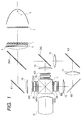
- Fig. 1 shows the optical arrangement of a projecting image display apparatus (projector apparatus) according to the first embodiment of the present invention.
- white illumination light emitted from a light source section 1 of an ultrahigh-pressure mercury-vapor lamp is reflected by a reflector 2 and transmitted through fly-eye lenses 3 and 4.
- the direction of polarization is aligned through a PS conversion element 5 by a mirror which separates light into p-polarized light and s-polarized light and a ⁇ /2-plate which changes the polarization direction.
- the light that emerges from the PS conversion element 5 passes through a condenser lens 6 and the like.
- a red-band light component is transmitted through a dichroic mirror DM1.
- Green- and blue-band light components are reflected by the dichroic mirror DM1.
- the blue-band light component is transmitted through a dichroic mirror DM2.
- the green-band light component is reflected by the dichroic mirror DM2.
- the dichroic mirrors form a color separation optical system.
- Each color light component becomes incident on a corresponding one of liquid crystal display elements 9R, 9G, and 9B to form each color image.
- the color images are synthesized by a dichroic prism 11 serving as a color synthesis optical system and then projected onto a projection surface (screen) (not shown) by a projecting lens 12 serving as a projecting optical system.
- a dichroic prism 11 serving as a color synthesis optical system
- a projecting lens 12 serving as a projecting optical system.
- Each of the above liquid crystal display elements is an image forming panel such as a liquid crystal display panel.
- a transmission-type image forming panel for passing light to form an image is used.
- the red-band light component transmitted through the dichroic mirror DM1 is changed in its optical path by 90° by a reflecting mirror M1, passes through a field lens 7R, and becomes incident on an incident-side polarizing plate 8RI and liquid crystal display element 9R.
- the liquid crystal display element 9R is driven in accordance with image information supplied from an image information supply apparatus (e.g., a personal computer, TV, video tape recorder, or DVD player) (not shown) and modulates the red-band light component incident thereon.
- an image information supply apparatus e.g., a personal computer, TV, video tape recorder, or DVD player
- the modulated red-band light component strikes an exit-side polarizing plate 10RO and dichroic prism 11 in this order.
- the optical path is changed by 90° by the dichroic prism 11.
- the light component becomes incident on the projecting lens 12.
- the dichroic prism 11 is a so-called cross dichroic prism formed by bonding four prisms with adhesive such that it has an almost cross-shaped wavelength selection reflecting (dichroic) layer.
- a so-called 3P (3-piece) or a 4P (4-piece) prism formed by bonding three or four prisms having different shapes may be used.
- the cross dichroic prism, 3P (3-piece) prism, or 4P (4-piece) prism constructs a color synthesis optical system.
- the green- and blue-band light components reflected and changed in their operation paths by 90° by the dichroic mirror DM1 become incident on the dichroic mirror DM2.
- the dichroic mirror DM2 has a characteristic for reflecting a green-band light component G.
- the green-band light component is reflected and changed in its optical path by 90° by the dichroic mirror DM2, transmitted through a field lens 7G, and becomes incident on an incident-side polarizing plate 8GI and liquid crystal display element 9G.
- the liquid crystal display element 9G is driven in accordance with image information supplied from an image information supply apparatus (not shown) and modulates the green-band light component incident thereon.
- the modulated green-band light component strikes an exit-side polarizing plate 10GO and dichroic prism 11 in this order, passes through the dichroic prism 11, and becomes incident on the projecting lens 12.
- the blue-band light component transmitted through the dichroic mirror DM2 is transmitted through a condenser lens 13, changed in its optical path by 90° by a reflecting mirror M2, transmitted through a relay lens 14, changed in its optical path by 90° again by a reflecting mirror M3, transmitted through a field lens 7B, and becomes incident on an incident-side polarizing plate 8BI and liquid crystal display element 9B.
- the liquid crystal display element 9B is driven in accordance with image information supplied from an image information supply apparatus (not shown) and modulates the blue-band light component incident thereon.
- the modulated blue-band light component strikes an exit-side polarizing plate 10BO and dichroic prism 11 in this order, is changed in its optical path by 90° by the dichroic prism 11, and becomes incident on the projecting lens 12.
- the light components in the respective color bands, which are synthesized by the dichroic prism 11, are projected onto the projection surface (screen) (not shown) by the projecting lens 12 and displayed as an enlarged image.
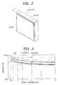
- a polarizer 8b (10b) is bonded to (held by) a transparent substrate 8a (10a) such that a predetermined polarizing characteristic can be exhibited.
- a thickness t of the transparent substrate which passes the red-band light component is set to be larger than that of the transparent substrate of the incident-side polarizing plate 8GI or exit-side polarizing plate 10GO which passes the green-band light component or the incident-side polarizing plate 8BI or exit-side polarizing plate 10BO which passes the blue-band light component.
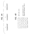
- Fig. 3 shows the relationship between the thickness of a transparent substrate and the temperature of the bonding interface of a polarizer when a polarizer having a predetermined area is bonded to a transparent substrate having a predetermined area, and the polarizer generates predetermined heat.
- the transparent substrates are formed from glass (BK7: heat conductivity: about 1.2 W/(m.K)), the transparent substrates are formed from fluorite (heat conductivity: about 9.7 W/(m ⁇ K)), and the transparent substrates are formed from sapphire (heat conductivity: 42 W/(m.K)).
- the transparent substrates are made of the same material, the maximum temperature becomes lower as the board thickness of the transparent substrate increases. That is, to prevent any degradation in performance due to heat of the polarizer, a large board thickness is more advantageous.
- the result obtained when a polarizer is bonded to a sapphire substrate having a board thickness of 0.5 mm is the same as the result obtained when a polarizer is bonded to a fluorite substrate having a board thickness of 1.1 mm.
- the transparent substrate 8a (10a) of the incident-side polarizing plate 8RI or exit-side polarizing plate 10RO which passes the red-band light component is made of fluorite, the heat load can be sufficiently relaxed by making the board thickness of the transparent substrate larger than those of the remaining transparent substrates. More specifically, when the transparent substrate which passes the red-band light component is thicker than the transparent substrates which pass the remaining band light components by about 20% (about 1.2 times), the difference becomes conspicuous.
- the fluorite transparent substrates used for the incident- and exit-side polarizing plates arranged in the optical path of the red-band light component are made thicker than the fluorite transparent substrates used for the incident- and exit-side polarizing plates arranged in the optical paths of the remaining band light components.
- the transparent substrates of the incident- and exit-side polarizing plates arranged in the optical path of the green- or blue-band light component, for which the heat load increases due to the cooling air channel or the like may be made thicker than those for the remaining band light components.
- the material of the transparent substrate is not limited to fluorite.
- a glass transparent substrate may be used depending on the degree of heat load. In this case as well, when the board thickness is increased by about 20%, the difference becomes conspicuous, as is apparent from Fig. 3 .
- the board thickness of a transparent substrate is changed in accordance with heat load whereby the heat of the polarizing plate can be effectively transmitted to the transparent substrate and efficiently radiated by the transparent substrate.
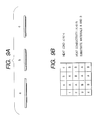
- incident- or exit-side polarizing plates a, b, and c are arranged in three optical paths of light components separated into three colors, respectively.
- a polarizer is bonded to a transparent substrate.
- the heat load on the respective polarizing plates increases in an order of a, b, and c (in the polarizing plates a, b, and c, the polarizing plate a has the highest heat load, and the polarizing plate c has the lowest heat load).
- the transparent substrate of the polarizing plate a is thicker (e.g., thicker by 1.2 times or more) than those of the polarizing plates b and c.
- Fig. 4B shows effective combinations when two or more kinds of materials are used for transparent substrates with the above arrangement.
- Fig. 4B shows a table of combinations when materials A and B (heat conductivity: A > B) are employed for the transparent substrates of the polarizing plates a, b, and c shown in Fig. 4A .
- materials A and B heat conductivity: A > B
- sapphire is used as the material A
- fluorite (and/or glass) is used as the material B.
- sapphire (and/or fluorite) is used as the material A
- glass is used as the material B.
- the transparent substrate used for the polarizing plate a is made of sapphire, i.e., the material A
- the transparent substrates used for the polarizing plates b and c are made of fluorite (or glass), i.e., the material B.
- the transparent substrate used for the polarizing plate a is made of sapphire, i.e., the material A
- the transparent substrate used for the polarizing plate b is made of fluorite, i.e., the material B
- the transparent substrate used for the polarizing plate c is made of glass, i.e., the material B.
- the heat load on a given polarizing plate is very high, a sapphire substrate is used only for the transparent substrate of that polarizing plate, and the board thickness of the transparent substrate is increased. With this arrangement, the polarizing plate can reliably stand the high heat load.
- incident- or exit-side polarizing plates d, e, and f are arranged in three optical paths of light components separated into three colors, respectively.
- a polarizer is bonded to a transparent substrate.
- the heat load on the respective polarizing plates increases in an order of d, e, and f (in the polarizing plates d, e and f, the polarizing plate d has the highest heat load, and the polarizing plate f has the lowest heat load).
- the transparent substrates of the polarizing plates d and e are thicker (e.g., thicker by 1.2 times or more) than that of the polarizing plate f.
- Fig. 5B shows effective combinations when two or more kinds of materials are used for transparent substrates with the above arrangement.
- Fig. 5B shows a table of combinations when materials C and D (heat conductivity: C > D) are employed for the transparent substrates of the polarizing plates d, e, and f shown in Fig. 5A .
- materials C and D heat conductivity: C > D
- sapphire is used as the material C
- fluorite and/or glass
- sapphire (and/or fluorite) is used as the material C
- glass is used as the material D.
- the transparent substrate used for the polarizing plate d is made of sapphire, i.e., the material C
- the transparent substrates used for the polarizing plates e and f are made of fluorite, i.e., the material D.
- the transparent substrate used for the polarizing plate d is made of sapphire, i.e., the material C
- the transparent substrate used for the polarizing plate e is made of fluorite (or glass), i.e., the material D
- the transparent substrate used for the polarizing plate f is made of glass (or fluorite), i.e., the material D.
- the material of a transparent substrate is selected, and the board thickness of the transparent substrate is changed in accordance with heat load whereby the heat of the polarizing plate can be effectively transmitted to the transparent substrate and efficiently radiated by the transparent substrate.
- Fig. 6 shows the optical arrangement of a projecting image display apparatus (projector apparatus) according to the second embodiment of the present invention.
- the same reference numerals as in the first embodiment denote the same components in the second embodiment.
- white light emitted from a light source section 1 of an ultrahigh-pressure mercury-vapor lamp is reflected by a reflector 2 and transmitted through fly-eye lenses 3 and 4.
- the direction of polarization is aligned through a PS conversion element 5 by a mirror which separates light into p-polarized light and s-polarized light and a ⁇ /2-plate which changes the polarization direction.
- the light that emerges from the PS conversion element 5 passes through a condenser lens 6 and the like.
- a dichroic mirror DM1 passes a red-band light component and reflects green- and blue-band light components.
- the blue-band light component is transmitted through a dichroic mirror DM2.
- the green-band light component is reflected by the dichroic mirror DM2.
- the dichroic mirrors form a color separation optical system.
- Each color light component becomes incident on a corresponding one of liquid crystal display elements 9R, 9G, and 9B and is modulated.
- the color light components are synthesized by a dichroic prism 11 serving as a color synthesis optical system and then projected onto a projection surface (screen) (not shown) by a projecting lens 12 serving as a projecting optical system.
- a dichroic prism 11 serving as a color synthesis optical system
- a projecting lens 12 serving as a projecting optical system.
- Each of the above liquid crystal display elements is an image forming panel such as a liquid crystal display panel.
- a transmission-type image forming panel for passing light to form an image is used.
- the red-band light component transmitted through the dichroic mirror DM1 is changed in its optical path by 90° by a reflecting mirror M1, passes through a field lens 7R, and becomes incident on an incident-side polarizing plate 18RI and liquid crystal display element 9R.
- the liquid crystal display element 9R is driven in accordance with image information supplied from an image information supply apparatus (e.g., a personal computer, TV, video tape recorder, or DVD player) (not shown) and modulates the red-band light component incident thereon.
- an image information supply apparatus e.g., a personal computer, TV, video tape recorder, or DVD player
- the modulated red-band light component strikes an exit-side polarizing plate 20RO and dichroic prism 11 in this order.
- the optical path is changed by 90° by the dichroic prism 11.
- the light component becomes incident on the projecting lens 12.
- the dichroic prism 11 is a so-called cross dichroic prism formed by bonding four prisms with adhesive such that it has an almost cross-shaped wavelength selection reflecting (dichroic) layer.
- a so-called 3P (3-piece) or a 4P (4-piece) prism formed by bonding three or four prisms having different shapes may be used.
- the cross dichroic prism, 3P (3-piece) prism, or 4P (4-piece) prism constructs a color synthesis optical system.
- the green- and blue-band light components reflected and changed in their operation paths by 90° by the dichroic mirror DM1 become incident on the dichroic mirror DM2.
- the dichroic mirror DM2 has a characteristic for reflecting a green-band light component G.
- the green-band light component is reflected and changed in its optical path by 90° by the dichroic mirror DM2, transmitted through a field lens 7G, and 5 becomes incident on an incident-side polarizing plate 8GI and liquid crystal display element 9G.
- the liquid crystal display element 9G is driven in accordance with image information supplied from an image information supply apparatus (not shown) and modulates the green-band light component incident thereon.
- the modulated green-band light component strikes an exit-side polarizing plate 10GO and dichroic prism 11 in this order, passes through the dichroic prism 11, and becomes incident on the projecting lens 12.
- the blue-band light component transmitted through the dichroic mirror DM2 is transmitted through a condenser lens 13, changed in its optical path by 90° by a reflecting mirror M2, transmitted through a relay lens 14, changed in its optical path by 90° again by a reflecting mirror M3, transmitted through a field lens 7B, and becomes incident on an incident-side polarizing plate 8BI and liquid crystal display element 9B.
- the liquid crystal display element 9B is driven in accordance with image information supplied from an image information supply apparatus (not shown) and modulates the blue-band light component incident thereon.
- the modulated blue-band light component strikes an exit-side polarizing plate 10BO and dichroic prism 11 in this order, is changed in its optical path by 90° by the dichroic prism 11, and becomes incident on the projecting lens 12.
- the light components in the respective color bands, which are synthesized by the dichroic prism ) 11, are projected onto the projection surface (screen) (not shown) by the projecting lens 12 and displayed as an enlarged image.
- a polarizer 18b (20b) is bonded to a transparent substrate 18a (20a) such that a predetermined polarizing characteristic can be exhibited.
- the transparent substrates corresponding to the red-, green-, and blue-band light components are to be made of the same material such as fluorite
- the area of a surface of the transparent substrate 18a (20a) which passes the red-band light component, to which the polarizer 18b (20b) is to be bonded is set to be larger than that of a surface, to which a polarizer is to be bonded, of the transparent substrate of the incident-side polarizing plate 8GI or exit-side polarizing plate 10GO which passes the green-band light component or the incident-side polarizing plate 8BI or exit-side polarizing plate 10BO which passes the blue-band light component.
- Fig. 8 shows the relationship between the area ratio of a transparent substrate to a polarizer (when a polarizer has a predetermined area, the bonding area of the polarizer) and the temperature of the surface of the transparent substrate, to which the polarizer is bonded when a polarizer having a predetermined area is bonded to each of transparent substrates having thicknesses of 1 mm, 2 mm, and 3 mm, and the polarizer generates predetermined heat.
- the material of a transparent substrate is fluorite.
- Fig. 8 The result shown in Fig. 8 is obtained when only cooling by natural convection of air is executed without forcible cooling.
- the maximum temperature of the bonding interface becomes lower as the ratio of the area of the bonding interface of the transparent substrate to the area of the polarizer (transparent substrate area/polarizer area) increases. That is, to prevent any degradation in performance due to heat of the polarizer, a high area ratio is more advantageous.
- the result obtained when a polarizer is bonded to a fluorite substrate having a thickness of 1 mm and an area ratio of 2.0 is the same as the result obtained when a polarizer is bonded to a fluorite substrate having a thickness of 3 mm and an area ratio of 1.2. Even when the material of a transparent substrate is sapphire or glass, the same characteristic as in fluorite can be exhibited.
- the heat load can be sufficiently relaxed by increasing the area ratio. More specifically, when the area ratio is higher than the area ratios of the transparent substrates which pass the remaining band light components to the polarizers by about 20% (about 1.2 times), the difference becomes conspicuous.
- the area ratio of the fluorite transparent substrates used for the incident- and exit-side polarizing plates arranged in the optical path of the red-band light component to the polarizers bonded to the transparent substrates is made higher than the area ratio of the fluorite transparent substrates used for the incident- and exit-side polarizing plates arranged in the optical paths of the remaining band light components to the polarizers bonded to the transparent substrates.
- the area ratio of the transparent substrates of the incident- and exit-side polarizing plates arranged in the optical path of the green- or blue-band light component, for which the heat load increases due to the cooling air channel or the like, may be made higher than those for the remaining band light components.
- the material of the transparent substrate is not limited to fluorite.
- a glass (or sapphire) transparent substrate may be used depending on the degree of heat load. In this case as well, when the area ratio is increased by about 20%, the difference becomes conspicuous.
- the area of a transparent substrate is changed in accordance with heat load whereby the heat of the polarizing plate can be effectively transmitted to the transparent substrate and efficiently radiated by the transparent substrate.
- incident- or exit-side polarizing plates a, b, and c are arranged in three optical paths of light components separated into three colors, respectively.
- a polarizer is bonded to a transparent substrate.
- the heat load on the respective polarizing plates increases in an order of a, b, and c (in the polarizing plates a, b, and c, the polarizing plate a has the highest heat load, and the polarizing plate c has the lowest heat load).
- the area of the transparent substrate of the polarizing plate a is larger (e.g., larger by 1.2 times or more) than the areas of the transparent substrates of the polarizing plates b and c.
- Fig. 9B shows effective combinations when two or more kinds of materials are used for transparent substrates with the above arrangement.
- Fig. 9B shows a table of combinations when materials A and B (heat conductivity: A > B) are employed for the transparent substrates of the polarizing plates a, b, and shown in Fig. 9A .
- materials A and B heat conductivity: A > B
- sapphire is used as the material A
- fluorite and/or glass
- sapphire (and/or fluorite) is used as the material A
- glass is used as the material B.
- the transparent substrate used for the polarizing plate a is made of sapphire, i.e., the material A
- the transparent substrates used for the polarizing plates b and c are made of fluorite (or glass), i.e., the material B.
- the transparent substrate used for the polarizing plate a is made of sapphire, i.e., the material A
- the transparent substrate used for the polarizing plate b is made of fluorite, i.e., the material B
- the transparent substrate used for the polarizing plate c is made of glass, i.e., the material B.
- the polarizing plate can reliably stand the high heat load.
- incident- or exit-side polarizing plates d, e, and f are arranged in three optical paths of light components separated into three colors, respectively.
- a polarizer is bonded to a transparent substrate.
- the heat load on the respective polarizing plates increases in an order of d, e, and f (in the polarizing plates d, e and f, the polarizing plate d has the highest heat load, and the polarizing plate f has the lowest heat load).
- the area of the transparent substrates of the polarizing plates d and e is larger (e.g., larger by 1.2 times or more) than the area of the transparent substrate of the polarizing plate f.
- Fig. 10B shows effective combinations when two or more kinds of materials are used for transparent substrates with the above arrangement.
- Fig. 10B shows a table of combinations when materials C and D (heat conductivity: C > D) are employed for the transparent substrates of the polarizing plates d, e, and f shown in Fig. 10A .
- materials C and D heat conductivity: C > D
- sapphire is used as the material C
- fluorite and/or glass
- sapphire (and/or fluorite) is used as the material C
- glass is used as the material D.
- the transparent substrate used for the polarizing plate d is made of sapphire, i.e., the material C
- the transparent substrates used for the polarizing plates e and f are made of fluorite (or glass), i.e., the material D.
- the transparent substrate used for the polarizing plate d is made of sapphire, i.e., the material C
- the transparent substrate used for the polarizing plate e is made of fluorite (or glass), i.e., the material D
- the transparent substrate used for the polarizing plate f is made of glass (or fluorite), i.e., the material D.
- the material of a transparent substrate is selected, and the area of the transparent substrate is changed in accordance with heat load whereby the heat of the polarizing plate can be effectively transmitted to the transparent substrate and efficiently radiated by the transparent substrate.
- Fig. 11 shows the optical arrangement of a projecting image display apparatus (projector apparatus) according to the third embodiment of the present invention.
- the same reference numerals as in the first embodiment denote the same components in the third embodiment.
- white light emitted from a light source section 1 of an ultrahigh-pressure mercury-vapor lamp is reflected by a reflector 2 and transmitted through fly-eye lenses 3 and 4.
- the direction of polarization is aligned through a PS conversion element 5 by a mirror which separates light into p-polarized light and s-polarized light and a ⁇ /2-plate which changes the polarization direction.
- the light that emerges from the PS conversion element 5 passes through a condenser lens 6 and the like.
- a dichroic mirror DM1 passes a red-band light component and reflects green- and blue-band light components.
- the blue-band light component is transmitted through a dichroic mirror DM2.
- the green-band light component is reflected by the dichroic mirror DM2.
- the dichroic mirrors form a color separation optical system.
- Each color light component becomes incident on a corresponding one of liquid crystal display elements 9R, 9G, and 9B and is modulated.
- the color light components are synthesized by a dichroic prism 11 serving as a color synthesis optical system and then projected onto a projection surface (screen) (not shown) by a projecting lens 12 serving as a projecting optical system.
- a dichroic prism 11 serving as a color synthesis optical system
- a projecting lens 12 serving as a projecting optical system.
- Each of the above liquid crystal display elements is an image forming panel such as a liquid crystal display panel.
- a transmission-type image forming panel for passing light to form an image is used.
- the red-band light component transmitted through the dichroic mirror DM1 is changed in its optical path by 90° by a reflecting mirror M1, passes through a field lens 28RI with polarizer, and becomes incident on the liquid crystal display element 9R.
- the liquid crystal display element 9R is driven in accordance with image information supplied from an image information supply apparatus (e.g., a personal computer, TV, video tape recorder, or DVD player) (not shown) and modulates the red-band light component incident thereon.
- an image information supply apparatus e.g., a personal computer, TV, video tape recorder, or DVD player
- the modulated red-band light component strikes an exit-side polarizing plate 10RO and dichroic prism 11 in this order.
- the optical path is changed by 90° by the dichroic prism 11.
- the light component becomes incident on the projecting lens 12.
- the dichroic prism 11 is a so-called cross dichroic prism formed by bonding four prisms with adhesive such that it has an almost cross-shaped wavelength selection reflecting (dichroic) layer.
- a so-called 3P (3-piece) or a 4P (4-piece) prism formed by bonding three or four prisms having different shapes may be used.
- the cross dichroic prism, 3P (3-piece) prism, or 4P (4-piece) prism constructs a color synthesis optical system.
- the green- and blue-band light components reflected and changed in their operation paths by 90° by the dichroic mirror DM1 become incident on the dichroic mirror DM2.
- the dichroic mirror DM2 has a characteristic for reflecting a green-band light component G.
- the green-band light component is reflected and changed in its optical path by 90° by the dichroic mirror DM2, transmitted through a field lens 7G, and becomes incident on an incident-side polarizing plate 8GI and liquid crystal display element 9G.
- the liquid crystal display element 9G is driven in accordance with image information supplied from an image information supply apparatus (not shown) and modulates the green-band light component incident thereon.
- the modulated green-band light component strikes an exit-side polarizing plate 10GO and dichroic prism 11 in this order, passes through the dichroic prism 11, and becomes incident on the projecting lens 12.
- the blue-band light component transmitted through the dichroic mirror DM2 is transmitted through a condenser lens 13, relay lens 14, reflecting mirrors M2 and M3, and field lens 7B and becomes incident on an incident-side polarizing plate 8BI and liquid crystal display element 9B.
- the liquid crystal display element 9B is driven in accordance with image information supplied from an image information supply apparatus (not shown) and modulates the blue-band light component incident thereon.
- the modulated blue-band light component strikes an exit-side polarizing plate 10BO and dichroic prism 11 in this order, is changed in its optical path by 90° by the dichroic prism 11, and becomes incident on the projecting lens 12.
- the light components in the respective color bands, which are synthesized by the dichroic prism 11, are projected onto the projection surface (screen) (not shown) by the projecting lens 12 and displayed as an enlarged image.
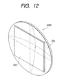
- the field lens 28RI used as the transparent substrate of the polarizing plate which passes a red-band light component is formed by bonding a polarizer 28b to the exit plane of a lens section (corresponding to a transparent substrate) 28a such that a predetermined polarizing characteristic can be exhibited.
- the field lens and transparent substrate are formed from the same material, i.e., fluorite.
- the field lens serving as one transparent substrate has a shape different from the planar shape of each of the remaining transparent substrates.
- the incident surface of the lens section 28a of the field lens is formed from a spherical surface (alternatively, a convex surface, concave surface, aspherical surface, or free-form surface may be possible). Its size or thickness at the center can be relatively freely set. That is, the surface area of one transparent substrate is larger than those of the remaining transparent substrates.
- the shape (the area or thickness of the lens 28a) of the field lens serving as one transparent substrate is set to be different (larger ) in area or thickness) from the planar shape of the transparent substrate of the incident-side polarizing plate 8GI or exit-side polarizing plate 10GO which passes the green-band light component or the incident-side polarizing plate 8BI or exit-side polarizing plate 10BO which passes the blue-band light component. That is, the field lens serving as one transparent substrate has a shape different from those of the remaining transparent substrates (the surface area of one transparent substrate (field lens) is larger than those of the remaining transparent substrates).
- the heat load can be sufficiently relaxed even when fluorite is used as the material of the transparent substrate (lens).
- an incident-side polarizer is bonded to the field lens serving as a transparent substrate arranged in the optical path of the red-band light component, and the shape of the field lens is optimized.
- the transparent substrate of the green or blue band, for which the heat load increases due to the cooling air channel or the like may serve as a field lens, and a polarizer may be bonded to the field lens.
- a polarizer is bonded to a field lens made of fluorite, and the shape of the field lens is optimized.
- a polarizer may be boned to a glass field lens, and the shape of the field lens may be optimized.
- the field lens has a planar surface on one side and a spherical lens section on the other side.
- the polarizer may be held by a planar surface on one side, and the surface on the other side may be formed into a wave shape or grating shape such that the surface area becomes larger than a planar surface.
- incident- or exit-side polarizing plates a, b, and c are arranged in three optical paths of light components separated into three colors, respectively.
- a polarizer is bonded to a transparent substrate.
- the transparent substrate of the polarizing plate a has a shape different from the planar shapes of the polarizing plates b and c and has a larger surface area and volume (a field lens in which one surface has a planar shape and the other surface has a spherical shape is used).
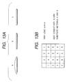
- Fig. 13B shows effective combinations when two or more kinds of materials are used for transparent substrates with the above arrangement.
- Fig. 13B shows a table of combinations when materials A and B (heat conductivity: A > B) are employed for the transparent substrates of the polarizing plates a, b, and c shown in Fig. 13A .
- materials A and B heat conductivity: A > B
- sapphire is used as the material A
- fluorite (and/or glass) is used as the material B.
- sapphire (and/or fluorite) is used as the material A
- glass is used as the material B.
- the transparent substrate used for the polarizing plate a is made of sapphire, i.e., the material A
- the transparent substrates used for the polarizing plates b and c are made of fluorite (or glass), i.e., the material B.
- the transparent substrate used for the polarizing plate a is made of sapphire, i.e., the material A
- the transparent substrate used for the polarizing plate b is made of fluorite, i.e., the material B
- the transparent substrate used for the polarizing plate c is made of glass, i.e., the material B.
- the field lens (the transparent substrate of the polarizing plate) can reliably stand the high heat load.
- incident- or exit-side polarizing plates d, e, and f are arranged in three optical paths of light components separated into three colors, respectively.
- a polarizer is bonded to a transparent substrate.
- the transparent substrates of the polarizing plates d and e have a shape different from the planar shape of the polarizing plate f and has a larger surface area and volume (field lenses in each of which one surface has a planar shape and the other surface has a spherical shape are used).
- Fig. 14B shows effective combinations when two or more kinds of materials are used for transparent substrates with the above arrangement.
- Fig. 14B shows a table of combinations when materials C and D (heat conductivity: C > D) are employed for the transparent substrates of the polarizing plates d, e, and f shown in Fig. 14A .
- materials C and D heat conductivity: C > D
- sapphire is used as the material C
- fluorite and/or glass
- sapphire (and/or fluorite) is used as the material C
- glass is used as the material D.
- the transparent substrate used for the polarizing plate d is made of sapphire (or fluorite), i.e., the material C
- the transparent substrates used for the polarizing plates e and f are made of fluorite (or glass), i.e., the material D.
- the transparent substrate used for the polarizing plate d is made of sapphire, i.e., the material C
- the transparent substrate used for the polarizing plate e is made of fluorite (or glass), i.e., the material D
- the transparent substrate used for the polarizing plate f is made of glass (or fluorite), i.e., the material D.
- the material of a transparent substrate is selected, and the shape (surface area) of the transparent substrate is changed in accordance with heat load whereby the heat of the polarizing plate can be effectively transmitted to the transparent substrate and efficiently radiated by the transparent substrate.
- a transparent substrate that holds a polarizer in the above-described embodiments is used in a projector apparatus in which a transmission-type image forming panel such as a liquid crystal display panel for passing light to form an image is used as an image forming panel.
- a transparent substrate that holds a polarizer in the above-described embodiments may be used in a projector apparatus in which a reflection-type image forming panel such as a liquid crystal display panel for reflecting light to form an image is used.
- the optical system uses a color separation optical system, color synthesis optical system, and a color separation/synthesis optical system having both functions of color separation and color synthesis.
- the material of a transparent substrate is selected, and the surface area (thickness, area, or volume) of the transparent substrate is changed in accordance with heat load whereby the heat of the polarizing plate can be effectively transmitted to the transparent substrate and efficiently radiated by the transparent substrate.
- the heat load on the polarizing plate can be effectively and sufficiently relaxed. Hence, the cost can be reduced while properly preventing any degradation in image quality due to heat.
Landscapes
- Physics & Mathematics (AREA)
- Engineering & Computer Science (AREA)
- Multimedia (AREA)
- Signal Processing (AREA)
- General Physics & Mathematics (AREA)
- Optics & Photonics (AREA)
- Chemical & Material Sciences (AREA)
- Crystallography & Structural Chemistry (AREA)
- Projection Apparatus (AREA)
- Liquid Crystal (AREA)
- Video Image Reproduction Devices For Color Tv Systems (AREA)
- Polarising Elements (AREA)
Applications Claiming Priority (3)
| Application Number | Priority Date | Filing Date | Title |
|---|---|---|---|
| JP2001161340 | 2001-05-29 | ||
| JP2002151625A JP4109901B2 (ja) | 2001-05-29 | 2002-05-24 | 画像表示装置 |
| EP02253731.0A EP1274255B1 (de) | 2001-05-29 | 2002-05-28 | Projektionsvorrichtung |
Related Parent Applications (1)
| Application Number | Title | Priority Date | Filing Date |
|---|---|---|---|
| EP02253731.0 Division | 2002-05-28 |
Publications (3)
| Publication Number | Publication Date |
|---|---|
| EP2384005A2 true EP2384005A2 (de) | 2011-11-02 |
| EP2384005A3 EP2384005A3 (de) | 2012-08-22 |
| EP2384005B1 EP2384005B1 (de) | 2013-10-16 |
Family
ID=26615903
Family Applications (2)
| Application Number | Title | Priority Date | Filing Date |
|---|---|---|---|
| EP11175550.0A Expired - Lifetime EP2384005B1 (de) | 2001-05-29 | 2002-05-28 | Projektionsgerät |
| EP02253731.0A Expired - Lifetime EP1274255B1 (de) | 2001-05-29 | 2002-05-28 | Projektionsvorrichtung |
Family Applications After (1)
| Application Number | Title | Priority Date | Filing Date |
|---|---|---|---|
| EP02253731.0A Expired - Lifetime EP1274255B1 (de) | 2001-05-29 | 2002-05-28 | Projektionsvorrichtung |
Country Status (4)
| Country | Link |
|---|---|
| US (3) | US6619803B2 (de) |
| EP (2) | EP2384005B1 (de) |
| JP (1) | JP4109901B2 (de) |
| CN (1) | CN100390601C (de) |
Families Citing this family (9)
| Publication number | Priority date | Publication date | Assignee | Title |
|---|---|---|---|---|
| JP4109901B2 (ja) | 2001-05-29 | 2008-07-02 | キヤノン株式会社 | 画像表示装置 |
| US20050007556A1 (en) * | 2003-02-04 | 2005-01-13 | Seiko Epson Corporation | Optical device and projector |
| US7073911B2 (en) * | 2003-03-14 | 2006-07-11 | Seiko Epson Corporation | Projector with improved heat radiation |
| JP2005266765A (ja) * | 2004-02-20 | 2005-09-29 | Seiko Epson Corp | プロジェクタ |
| JP4165479B2 (ja) * | 2004-09-08 | 2008-10-15 | セイコーエプソン株式会社 | プロジェクタ |
| JP2007025406A (ja) | 2005-07-19 | 2007-02-01 | Sanyo Electric Co Ltd | プロジェクタ装置 |
| JP2007163726A (ja) * | 2005-12-13 | 2007-06-28 | Seiko Epson Corp | プロジェクタ及び光学部品 |
| JP4442687B2 (ja) * | 2007-12-12 | 2010-03-31 | セイコーエプソン株式会社 | プロジェクタ |
| JP5447783B2 (ja) * | 2008-12-10 | 2014-03-19 | 株式会社リコー | 光走査装置、この光走査装置を備えた画像形成装置 |
Citations (3)
| Publication number | Priority date | Publication date | Assignee | Title |
|---|---|---|---|---|
| JPH11231277A (ja) | 1998-02-12 | 1999-08-27 | Sharp Corp | 液晶プロジェクター |
| EP1274255A1 (de) | 2001-05-29 | 2003-01-08 | Canon Kabushiki Kaisha | Projektionsvorrichtung |
| EP2253731A1 (de) | 2003-04-01 | 2010-11-24 | Nippon Mining & Metals Co., Ltd. | Tantal-Sputtertarget |
Family Cites Families (19)
| Publication number | Priority date | Publication date | Assignee | Title |
|---|---|---|---|---|
| JPH01314286A (ja) * | 1988-06-14 | 1989-12-19 | Seiko Epson Corp | 投写型表示装置の冷却装置 |
| JPH07248480A (ja) | 1994-03-09 | 1995-09-26 | Furukawa Electric Co Ltd:The | 液晶プロジェクタの冷却装置 |
| JPH10123964A (ja) * | 1996-08-30 | 1998-05-15 | Sony Corp | 液晶表示装置 |
| US6111700A (en) * | 1996-09-05 | 2000-08-29 | Fujitsu Limited | Optical display device having a reflection-type polarizer |
| JP3443549B2 (ja) | 1998-03-27 | 2003-09-02 | 京セラ株式会社 | 偏光板 |
| JP2000039584A (ja) * | 1998-07-23 | 2000-02-08 | Fuji Photo Optical Co Ltd | プロジェクタ装置 |
| JP3713969B2 (ja) * | 1998-08-26 | 2005-11-09 | セイコーエプソン株式会社 | 投写型表示装置 |
| JP2000075258A (ja) * | 1998-08-27 | 2000-03-14 | Seiko Epson Corp | 投写型表示装置 |
| JP2000089364A (ja) | 1998-09-09 | 2000-03-31 | Seiko Epson Corp | 光変調装置およびこの光変調装置を利用した投写型表示装置 |
| JP2000098329A (ja) * | 1998-09-25 | 2000-04-07 | Seiko Epson Corp | 投写型表示装置 |
| EP1016894A3 (de) | 1998-12-28 | 2001-03-28 | Kyocera Corporation | Flüssigkristallanzeige |
| US6414781B1 (en) * | 1999-03-30 | 2002-07-02 | Seiko Epson Corporation | Electro-optical device and projection display device including the same |
| JP3697134B2 (ja) * | 1999-03-30 | 2005-09-21 | セイコーエプソン株式会社 | 電気光学装置及びこれを備えた投射型表示装置 |
| JP2000352615A (ja) * | 1999-06-11 | 2000-12-19 | Seiko Epson Corp | ガラス付偏光板及び液晶プロジェクタ |
| JP2001100311A (ja) * | 1999-07-23 | 2001-04-13 | Seiko Epson Corp | プロジェクタ |
| JP2001042424A (ja) * | 1999-07-28 | 2001-02-16 | Seiko Epson Corp | 投写型表示装置 |
| JP2001272513A (ja) * | 2000-03-24 | 2001-10-05 | Seiko Epson Corp | 光学部品およびこれを用いたプロジェクタ |
| JP2001272671A (ja) * | 2000-03-24 | 2001-10-05 | Seiko Epson Corp | プロジェクタ |
| JP2001075070A (ja) | 2000-08-03 | 2001-03-23 | Sharp Corp | 液晶プロジェクター |
-
2002
- 2002-05-24 JP JP2002151625A patent/JP4109901B2/ja not_active Expired - Lifetime
- 2002-05-28 EP EP11175550.0A patent/EP2384005B1/de not_active Expired - Lifetime
- 2002-05-28 EP EP02253731.0A patent/EP1274255B1/de not_active Expired - Lifetime
- 2002-05-29 CN CNB021470359A patent/CN100390601C/zh not_active Expired - Lifetime
- 2002-05-29 US US10/157,556 patent/US6619803B2/en not_active Expired - Lifetime
-
2003
- 2003-07-29 US US10/629,113 patent/US6877858B2/en not_active Expired - Lifetime
-
2004
- 2004-10-01 US US10/957,515 patent/US6988804B2/en not_active Expired - Lifetime
Patent Citations (3)
| Publication number | Priority date | Publication date | Assignee | Title |
|---|---|---|---|---|
| JPH11231277A (ja) | 1998-02-12 | 1999-08-27 | Sharp Corp | 液晶プロジェクター |
| EP1274255A1 (de) | 2001-05-29 | 2003-01-08 | Canon Kabushiki Kaisha | Projektionsvorrichtung |
| EP2253731A1 (de) | 2003-04-01 | 2010-11-24 | Nippon Mining & Metals Co., Ltd. | Tantal-Sputtertarget |
Also Published As
| Publication number | Publication date |
|---|---|
| EP2384005A3 (de) | 2012-08-22 |
| JP2003090982A (ja) | 2003-03-28 |
| US20050057728A1 (en) | 2005-03-17 |
| EP1274255A1 (de) | 2003-01-08 |
| CN1402045A (zh) | 2003-03-12 |
| US6988804B2 (en) | 2006-01-24 |
| US20030007133A1 (en) | 2003-01-09 |
| JP4109901B2 (ja) | 2008-07-02 |
| CN100390601C (zh) | 2008-05-28 |
| US6877858B2 (en) | 2005-04-12 |
| US20040070733A1 (en) | 2004-04-15 |
| EP1274255B1 (de) | 2013-07-17 |
| US6619803B2 (en) | 2003-09-16 |
| EP2384005B1 (de) | 2013-10-16 |
Similar Documents
| Publication | Publication Date | Title |
|---|---|---|
| US7130120B2 (en) | Prism, projection and optical component | |
| US8197067B2 (en) | Projection type display apparatus with means for removing unnecessary polarized components of color lights | |
| US7564505B2 (en) | Optical device and projector equipped with the same | |
| US6678015B2 (en) | Color separating/synthesizing apparatus | |
| JPH0915529A (ja) | 像投写装置 | |
| JP2004020621A (ja) | 反射型映像投射装置と、それを用いた投写型映像ディスプレイ装置、及び、それに用いる光源装置 | |
| US20090135316A1 (en) | Projection image display apparatus and polarization converter | |
| EP2384005B1 (de) | Projektionsgerät | |
| EP1909507B1 (de) | Bildanzeigevorrichtung | |
| US6611381B2 (en) | Display element, polarizing plate, and display apparatus and projecting apparatus using the display element and polarizing plate | |
| CN100437340C (zh) | 图像投影装置 | |
| US7472995B2 (en) | Wavelength-selective polarization conversion element, projection displaying optical system and image projection apparatus | |
| JP3654798B2 (ja) | 画像表示装置および照明装置 | |
| US7237901B2 (en) | Projection type image display device, rear projection type image display device, optical unit, and screen unit | |
| JP2001083604A (ja) | 光束圧縮手段、光学エンジン及びこれを用いた映像表示装置 | |
| EP1445963A1 (de) | Optisches Farbkombinierungssystem für Lichteinfall in weitem Winkel | |
| JPH05150191A (ja) | 直線偏光変換装置 | |
| JP3659209B2 (ja) | 光学ユニット及びそれを用いた映像表示装置 | |
| CN100390604C (zh) | 投影装置 | |
| JP2002098937A (ja) | 3板式反射型液晶プロジェクタ装置 | |
| JP2006106777A (ja) | 画像表示装置 | |
| JP3979106B2 (ja) | 液晶プロジェクタ | |
| JP2004333685A (ja) | 画像表示装置 | |
| JP2004037584A (ja) | 画像表示装置 | |
| JP2000155300A (ja) | 液晶プロジェクタ |
Legal Events
| Date | Code | Title | Description |
|---|---|---|---|
| AC | Divisional application: reference to earlier application |
Ref document number: 1274255 Country of ref document: EP Kind code of ref document: P |
|
| AK | Designated contracting states |
Kind code of ref document: A2 Designated state(s): DE FR GB IT NL |
|
| PUAI | Public reference made under article 153(3) epc to a published international application that has entered the european phase |
Free format text: ORIGINAL CODE: 0009012 |
|
| PUAL | Search report despatched |
Free format text: ORIGINAL CODE: 0009013 |
|
| AK | Designated contracting states |
Kind code of ref document: A3 Designated state(s): DE FR GB IT NL |
|
| RIC1 | Information provided on ipc code assigned before grant |
Ipc: H04N 5/74 20060101ALI20120719BHEP Ipc: G02B 27/10 20060101ALI20120719BHEP Ipc: H04N 9/31 20060101AFI20120719BHEP |
|
| 17P | Request for examination filed |
Effective date: 20130222 |
|
| RIC1 | Information provided on ipc code assigned before grant |
Ipc: G02B 27/10 20060101ALI20130312BHEP Ipc: H04N 9/31 20060101AFI20130312BHEP Ipc: H04N 5/74 20060101ALI20130312BHEP |
|
| GRAP | Despatch of communication of intention to grant a patent |
Free format text: ORIGINAL CODE: EPIDOSNIGR1 |
|
| INTG | Intention to grant announced |
Effective date: 20130429 |
|
| GRAS | Grant fee paid |
Free format text: ORIGINAL CODE: EPIDOSNIGR3 |
|
| GRAA | (expected) grant |
Free format text: ORIGINAL CODE: 0009210 |
|
| AC | Divisional application: reference to earlier application |
Ref document number: 1274255 Country of ref document: EP Kind code of ref document: P |
|
| AK | Designated contracting states |
Kind code of ref document: B1 Designated state(s): DE FR GB IT NL |
|
| REG | Reference to a national code |
Ref country code: GB Ref legal event code: FG4D |
|
| REG | Reference to a national code |
Ref country code: DE Ref legal event code: R096 Ref document number: 60245663 Country of ref document: DE Effective date: 20131212 |
|
| REG | Reference to a national code |
Ref country code: NL Ref legal event code: VDEP Effective date: 20131016 |
|
| PG25 | Lapsed in a contracting state [announced via postgrant information from national office to epo] |
Ref country code: NL Free format text: LAPSE BECAUSE OF FAILURE TO SUBMIT A TRANSLATION OF THE DESCRIPTION OR TO PAY THE FEE WITHIN THE PRESCRIBED TIME-LIMIT Effective date: 20131016 |
|
| REG | Reference to a national code |
Ref country code: DE Ref legal event code: R097 Ref document number: 60245663 Country of ref document: DE |
|
| PLBE | No opposition filed within time limit |
Free format text: ORIGINAL CODE: 0009261 |
|
| STAA | Information on the status of an ep patent application or granted ep patent |
Free format text: STATUS: NO OPPOSITION FILED WITHIN TIME LIMIT |
|
| PG25 | Lapsed in a contracting state [announced via postgrant information from national office to epo] |
Ref country code: IT Free format text: LAPSE BECAUSE OF FAILURE TO SUBMIT A TRANSLATION OF THE DESCRIPTION OR TO PAY THE FEE WITHIN THE PRESCRIBED TIME-LIMIT Effective date: 20131016 |
|
| 26N | No opposition filed |
Effective date: 20140717 |
|
| REG | Reference to a national code |
Ref country code: DE Ref legal event code: R097 Ref document number: 60245663 Country of ref document: DE Effective date: 20140717 |
|
| REG | Reference to a national code |
Ref country code: FR Ref legal event code: PLFP Year of fee payment: 15 |
|
| REG | Reference to a national code |
Ref country code: FR Ref legal event code: PLFP Year of fee payment: 16 |
|
| REG | Reference to a national code |
Ref country code: FR Ref legal event code: PLFP Year of fee payment: 17 |
|
| PGFP | Annual fee paid to national office [announced via postgrant information from national office to epo] |
Ref country code: FR Payment date: 20210421 Year of fee payment: 20 Ref country code: DE Payment date: 20210421 Year of fee payment: 20 |
|
| PGFP | Annual fee paid to national office [announced via postgrant information from national office to epo] |
Ref country code: GB Payment date: 20210422 Year of fee payment: 20 |
|
| REG | Reference to a national code |
Ref country code: DE Ref legal event code: R071 Ref document number: 60245663 Country of ref document: DE |
|
| REG | Reference to a national code |
Ref country code: GB Ref legal event code: PE20 Expiry date: 20220527 |
|
| PG25 | Lapsed in a contracting state [announced via postgrant information from national office to epo] |
Ref country code: GB Free format text: LAPSE BECAUSE OF EXPIRATION OF PROTECTION Effective date: 20220527 |