EP2379995B1 - Wägezelle - Google Patents
Wägezelle Download PDFInfo
- Publication number
- EP2379995B1 EP2379995B1 EP09798883.6A EP09798883A EP2379995B1 EP 2379995 B1 EP2379995 B1 EP 2379995B1 EP 09798883 A EP09798883 A EP 09798883A EP 2379995 B1 EP2379995 B1 EP 2379995B1
- Authority
- EP
- European Patent Office
- Prior art keywords
- load cell
- force
- cell according
- bending beam
- embodied
- Prior art date
- Legal status (The legal status is an assumption and is not a legal conclusion. Google has not performed a legal analysis and makes no representation as to the accuracy of the status listed.)
- Active
Links
Images
Classifications
-
- G—PHYSICS
- G01—MEASURING; TESTING
- G01G—WEIGHING
- G01G3/00—Weighing apparatus characterised by the use of elastically-deformable members, e.g. spring balances
- G01G3/12—Weighing apparatus characterised by the use of elastically-deformable members, e.g. spring balances wherein the weighing element is in the form of a solid body stressed by pressure or tension during weighing
-
- G—PHYSICS
- G01—MEASURING; TESTING
- G01G—WEIGHING
- G01G21/00—Details of weighing apparatus
- G01G21/30—Means for preventing contamination by dust
-
- G—PHYSICS
- G01—MEASURING; TESTING
- G01L—MEASURING FORCE, STRESS, TORQUE, WORK, MECHANICAL POWER, MECHANICAL EFFICIENCY, OR FLUID PRESSURE
- G01L1/00—Measuring force or stress, in general
- G01L1/26—Auxiliary measures taken, or devices used, in connection with the measurement of force, e.g. for preventing influence of transverse components of force, for preventing overload
Definitions
- the invention relates to a load cell, preferably for an aseptic platform scale, according to the preamble of patent claim 1.
- Load cells are special forms of load cells and designed to build weighing devices. Such weighing devices are often used in the food supply, so they often have to comply with special hygiene rules. Therefore, it is necessary for the load cells used there that they are constructed so that no dirt or food residues can accumulate permanently on their surfaces or at least must be easily removable. Furthermore, such load cells often have horizontal surfaces, gaps and depressions which are hardly accessible and therefore difficult to clean, where bacteria, viruses and fungi readily accumulate. Therefore, when using load cells in many areas of the chemical, pharmaceutical, cosmetic and food industries, it is essential that they are easy to clean and as far as possible have no surface areas on which dirt, food residues, chemicals, bacteria, viruses and fungi attach, penetrate or can form.
- a hermetically sealed Meß bodinauf choir which represents a load cell, is from the DE 10 2004 047 508 B3 known, which is designed as horizontally installable bending beam.
- This bending beam consists of a force introduction and a force receiving part, between which a force measuring element is arranged.
- the force measuring element consists of a vertical spiral spring, which was made by two opposite horizontal transverse holes in the middle bending beam part and on the two sides strain gauges as Scherkraftaufillon are applied, which generate a proportional electric signal at a weight load.
- For hermetic sealing cup-shaped metal sheet metal parts are welded in the holes, which close the sensitive electrical measuring elements hermetically sealed.
- this load cell is rod-shaped and equipped with largely flat outer surfaces, but especially on the horizontally extending top surface food or liquid residues can settle, which tend in connection with moisture to increase bacteria or viruses. Furthermore, dirt and food components which are difficult to clean and which could form fungi and bacteria could also adhere to the cup-shaped depressions. Therefore, such a hermetically sealed load cell in aseptic areas according to relevant hygiene regulations is often not applicable.
- a load cell for an electromechanical platform scale which consists essentially of a cylindrical rod from which at least pourable food and liquids would drain by gravity.
- one side of the bending rod is fastened to the balance housing by means of two screws, while the opposite end is connected as a flattened round rod to the weighing platform, wherein the weight force can be introduced transversely to the longitudinal direction.
- the strain gauges are likely to be applied, so that such a weighing cell is not cleaned with aqueous cleaning agents can not always be used in the food industry or in aseptic areas.
- Another load cell with cylindrical horizontally arranged housing is from the DE OS 28 18 140 known to be completely protected from external influences.
- a horizontal round rod is arranged in the housing body, which is fastened in a self-supporting tube at its one end region.
- strain gauges are applied to the outer surface, which generate a strain on the outer surface of the tube with a vertical force introduction into the end point of the rod.
- the self-supporting tube is hermetically sealed by a cylindrical closure sleeve as a housing part.
- the introduction of force via a bolt in an open at least downwardly open chamber in which a force introduction loop surrounds the rod, which is movably guided in this open chamber. Since this chamber is not hermetically sealed, it can penetrate dirt and liquid residues that are hardly removable, so that this load cell is not usable in contact with food.
- the invention is therefore based on the object, a hermetically sealed load cell further so that it is easy to clean and contains no gaps, depressions and horizontal surface parts, in and on which residues, dirt, bacteria, viruses or fungi settle or multiply, so that it can also be used in aseptic environment, in particular in food processing plants.
- the invention has the advantage that, because of the horizontal installation position, it also has only vertically sloping surface parts, so that all foods, cosmetics or pharmaceutical components that come into contact with it are difficult to set, whereby fungus, virus or bacteria formation is largely prevented ,
- the sealed encapsulation of the load cell makes it easy to clean and disinfect with aqueous solutions that such load cells are advantageously used in the aseptic area.
- the force-measuring element is formed as a double bending beam, with which advantageously very high measuring accuracies can be achieved.
- load cells therefore, it is also possible to produce scales that are subject to legal requirements.
- the entire load cell is made of a high-strength stainless steel, so that such a load cell is usable even with high humidity and aggressive environmental influences and therefore represents a very durable design that is not attacked by most chemicals or pharmaceutical commodities.
- the load cell with a protective layer which has a surface which is difficult to adhere, so that free-flowing or liquid materials coming into contact with it flow away without residue and thus prevents nucleation, in particular of pathogens, without significant cleaning measures becomes.
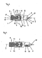
- a hermetically sealed load cell which is rotationally symmetrical, being arranged in the longitudinal direction between the force introduction 1 and Kraftaus effetselement 2 a double bending beam 3, which is closed by two provided at its end portions ring members 5, 6 and a tube sleeve 4 welded thereto , wherein the ring elements 5, 6 concentrically encircling thin points as a membrane 7, 8, which connect the pipe sleeve 4 bendable soft with the force introduction 1 and the Kraftaus effetselement 2 and the double bending beam 3.
- the load cell consists of a central longitudinal body, from which the force introduction element 1, the force diverting element 2, the double bending beam 3 and the two ring elements 5, 6 are worked out.
- the longitudinal body is preferably made of a high-quality stainless bending elastic stainless steel, on the finished Condition, the tube sleeve 4 slipped and welded to the two ring elements 5, 6 airtight.
- the central longitudinal body is preferably 120 mm long and about 40 mm in diameter.
- Between the force introduction element 1 and the force diverting element 2 of the double bending beam 3 is arranged, which contains a cuboid center part 14.
- a horizontal recess 11 is provided in the middle part 14, which has a four-leaf holes a cloverleaf-like cross-section.
- two tapered round connecting pieces 13, 16 are attached, which connect the double bending beam 3 on one side with the force introduction element 1 and on the opposite side with the force diverting element 2.
- a ring element 5, 6 is mounted transversely to the longitudinal axis 9, whose outer diameter corresponds to the inner diameter of the tubular sleeve 4 and is greater than the diameter of the force introduction element 1 and the Kraftaustechnischselements 2, and preferably about 39 mm.
- the two ring elements 5, 6 are concentrically concave on the annular surface facing the double bending beam 3 and thereby form a concentrically encircling first and second membrane 8, whose thickness is preferably 0.3 mm.
- both the force introduction element 1 and the force extraction element 2 are formed identically in their outer shape and both arranged symmetrically to the longitudinal 9 and transverse axis 10.
- a central longitudinal bore 22 is provided in the longitudinal direction, which extends at least to the recess 11 and in which the leads for the strain gauges are performed. Therefore, a connection cable 18 is still sealed in the force receiving element 2, in which the connection lines are guided sealed to the outside.
- two horizontal threaded holes 19 are still mounted on the end face 17 of the Kraftaus effetselements 2, and for fixing a weighing platform 1 two identical threaded holes 19 are also provided on the end face of the force introduction element.
- the two parallel end faces 17 represent vertical attachment surfaces, so that such load cells can be used not only for platform scales, but also for any other weighing devices in which the weight F perpendicular to the longitudinal axis 9 in the end face 17 of the load cell can be introduced.
- the tube sleeve 4 consists preferably also of a high-strength stainless steel, wherein its length corresponds to the distance between the two ring elements 5, 6 and it is welded airtight with the radial outer edges.
- the tube sleeve 4 is formed rigid, with its outer surface has only a small predetermined roughness, which is preferably produced by an electropolishing, so that it has a good running and easy to clean surface.
- FIG. 2 The drawing shows an alternative embodiment of a load cell, which only in the formation of the force introduction element 1 and the Kraftaus effetselements 2 from the load cell to Fig. 1 different from the drawing.
- the load cell is after Fig. 2 the drawing provided for a horizontal mounting in a weighing device. Therefore, on the cylindrical surface of the force introduction element 1 above a flattening 23 and the force discharge element 2 below a flattening 23 is provided as a plane horizontal mounting surface 20, in each of which two threaded holes 19 are introduced transversely to the longitudinal axis 9.
- both versions of the load cells are substantially rotationally symmetrical and preferably provided for horizontal installation.
- both versions By covering the flat or flattened mounting surfaces 17, 20 by fasteners of the weighing device both versions have only downwardly inclined rounded surfaces, where free-flowing or liquid goods can drain down. Since the entire surfaces of the load cells are preferably designed with only a small roughness, no undercut and no narrow gaps, it can hardly adhere to flowable goods or liquids. In a further embodiment is still provided to provide the load cells in addition to a hard-adhering surface coating such. As polytetrafluoroethylene (Teflon), which additionally prevents adhesion and cleaning ability is improved. Therefore, such load cells are preferably used in the food supply, with any nucleation in particular the disease germs or their multiplication must be prevented.
- Teflon polytetrafluoroethylene
Landscapes
- Physics & Mathematics (AREA)
- General Physics & Mathematics (AREA)
- Measurement Of Force In General (AREA)
- Apparatus Associated With Microorganisms And Enzymes (AREA)
Description
- Die Erfindung betrifft eine Wägezelle, vorzugsweise für eine aseptische Plattformwaage, gemäß dem Oberbegriff des Patentanspruchs 1.
- Wägezellen sind Sonderformen der Kraftaufnehmer und zum Aufbau von Wägevorrichtungen vorgesehen. Derartige Wägevorrichtungen werden häufig auch bei der Lebensmittelversorgung eingesetzt, so dass sie oft besonderen Hygienevorschriften genügen müssen. Deshalb ist es auch bei den dort verwendeten Wägezellen notwendig, dass diese so aufgebaut sind, dass sich an ihren Oberflächen kein Schmutz und keine Lebensmittelreste dauerhaft ansammeln kann oder zumindest leicht entfernbar sein muss. Des Weiteren befinden sich an derartigen Wägezellen häufig waagerechte Flächen, Spalten und Vertiefungen, die kaum zugänglich sind und deshalb nur schwer gereinigt werden können, wo sich dann leicht Bakterien, Viren und Pilze festsetzen. Deshalb ist es beim Einsatz von Wägezellen in vielen Bereichen der chemischen, pharmazeutischen, kosmetischen und Lebensmittelindustrie notwendig, dass diese leicht zu reinigen sind und möglichst keine Oberflächenbereiche aufweisen, auf denen sich Schmutz, Lebensmittelreste, Chemikalien, Bakterien, Viren und Pilze festsetzen, eindringen oder bilden können.
- Ein hermetisch dichter Messgrößenaufnehmer, der eine Wägezelle darstellt, ist aus der
DE 10 2004 047 508 B3 bekannt, der als horizontal einbaubarer Biegebalken ausgebildet ist. Dieser Biegebalken besteht aus einem Krafteinleitungs- und einem Kraftaufnahmeteil, zwischen denen ein Kraftmesselement angeordnet ist. Dabei besteht das Kraftmesselement aus einer vertikalen Biegefeder, die durch zwei gegenläufige horizontale Querbohrungen im mittleren Biegebalkenteil hergestellt wurde und an der beidseitig Dehnungsmessstreifen als Scherkraftaufnehmer appliziert sind, die bei einer Gewichtsbelastung ein proportionales elektrisches Signal erzeugen. Zur hermetischen Abdichtung sind dabei in den Bohrungen napfförmige metallische Blechteile eingeschweißt, die die empfindlichen elektrischen Messelemente hermetisch dicht verschließen. Dadurch wird hauptsächlich verhindert, dass Feuchtigkeit und andere korrodierende Schmutzpartikel mit den empfindlichen Messelementen in Berührung kommen, so dass eine langlebige Wägezelle geschaffen wurde. Diese Wägezelle ist zwar stabförmig und mit weitgehend flachen Außenflächen ausgestattet, wobei sich aber insbesondere auf der horizontal verlaufenden Deckfläche Lebensmittel- oder Flüssigkeitsreste absetzen können, die in Verbindung mit Feuchtigkeit zur Vermehrung von Bakterien oder Viren neigen. Des Weiteren könnten auch in den napfförmigen Vertiefungen Schmutz- und Lebensmittelbestandteile anhaften, die nur schwer zu reinigen sind, und in denen sich Pilze und Bakterien bilden könnten. Deshalb ist eine derartige auch hermetisch abgedichtete Wägezelle in aseptischen Bereichen nach einschlägigen Hygienevorschriften oft nicht einsetzbar. - Aus der
DE OS 37 15 572 - Eine weitere Wägezelle mit zylinderförmigem horizontal angeordnetem Gehäuse ist aus der
DE OS 28 18 140 bekannt, die gegenüber Fremdeinflüssen vollkommen geschützt sein soll. Dabei ist im Gehäusekörper ein horizontaler runder Stab angeordnet, der in einem freitragenden Rohr an dessen einem Endbereich befestigt ist. An dem freitragenden Rohr sind auf dessen äußerer Mantelfläche Dehnungsmessstreifen appliziert, die bei einer vertikalen Krafteinleitung in den Endpunkt des Stabes eine Dehnung auf der äußeren Mantelfläche des Rohres erzeugen. Dabei ist das freitragende Rohr von einer zylinderförmigen Verschlusshülse als Gehäuseteil hermetisch dicht verschlossen. Allerdings wird die Krafteinleitung über einen Schraubbolzen in einer mindestens nach unten offenen Kammer ausgeführt, in der eine Krafteinleitungsöse den Stab umgreift, der in dieser offenen Kammer beweglich geführt ist. Da diese Kammer nicht hermetisch verschlossen ist, können darin Schmutz und Flüssigkeitsreste eindringen, die kaum entfernbar sind, so dass diese Wägezelle im Kontakt mit Lebensmitteln nicht verwendbar ist. - Aus der
EP 1 698 871 A1 ist ein Einbausatz für eine Wägezelle vorbekannt, der insbesondere im Bereich der chemischen und pharmazeutischen, der Lebensmittel- und Kosmetikindustrie einsetzbar ist. Dabei enthält dieser Einbausatz eine vertikal angeordnete Wägezelle, die zwischen zwei parallelen horizontal angeordneten Montageplatten angeordnet ist. Als Krafteinleitungs- und Kraftausleitungselemente sind offensichtlich zwei runde Druckstücke vorgesehen, zwischen denen die Wägezelle angeordnet ist. Die Wägezelle ist dabei in einem runden, konisch verlaufenden Gehäuse verschlossen angeordnet, das so in die Druckstücke eingreift oder diese umfasst, dass dieser Einbausatz gut reinigbar ist und offensichtlich wenig Spalten und Hohlräume besitzt, in denen sich Bakterien, Viren und Pilze bilden können. Allerdings sind hierbei die Druckstücke als Krafteinleitungs- oder Kraftausleitungselemente nur lose mit der Wägezelle verbunden, so dass eine derartige Wägezelle nur vertikal einbaubar ist und auch nicht fest mit der Waage verbunden werden kann, so dass stets noch ein Einbausatz zusätzlich benötigt wird. -
US 2004/060372 A1 undUS 4 619 147 A zeigen weitere Wägezellen. - Der Erfindung liegt deshalb die Aufgabe zugrunde, eine hermetisch dichte Wägezelle so weiterzuentwickeln, dass diese leicht zu reinigen ist und keine Spalten, Vertiefungen und waagerechten Flächenteile enthält, in und auf denen sich Rückstände, Schmutz, Bakterien, Viren oder Pilze festsetzen oder vermehren können, so dass sie auch in aseptischer Umgebung, insbesondere in Anlagen zur Lebensmittelverarbeitung, einsetzbar ist.
- Diese Aufgabe wird durch die im Patentanspruch 1 angegebene Erfindung gelöst. Weiterbildungen und vorteilhafte Ausführungsbeispiele der Erfindung sind in den Unteransprüchen angegeben.
- Die Erfindung hat den Vorteil, dass sie wegen der horizontalen Einbaulage auch nur vertikal abfallende Flächenteile aufweist, so dass alle damit in Verbindung kommenden Lebensmittel, Kosmetika- oder Pharmabestandteile sich nur schwer festsetzen können, wodurch eine Pilz-, Viren- oder Bakterienbildung weitgehend verhindert wird.
- Durch die verschweißte Kapselung der Wägezelle ist diese auch gut mit wässrigen Lösungen reinigbar und desinfizierbar, so dass derartige Wägezellen vorteilhafterweise auch im aseptischen Bereich einsetzbar sind.
- Bei einer besonderen Ausführungsart der Erfindung ist vorgesehen, das Kraftmesselement als Doppelbiegebalken auszubilden, mit dem vorteilhafterweise sehr hohe Messgenauigkeiten erzielbar sind. Mit derartigen Wägezellen sind deshalb vorteilhafterweise auch eichpflichtige Waagen herstellbar.
- Bei einer anderen besonderen Ausführungsart besteht die gesamte Wägezelle aus einem hochfesten rostfreien Edelstahl, so dass eine derartige Wägezelle auch bei hoher Luftfeuchtigkeit und aggressiven Umgebungseinflüssen verwendbar ist und deshalb eine sehr langlebige Ausführung darstellt, die auch von den meisten Chemikalien oder pharmazeutischen Grundstoffen nicht angegriffen wird. Dabei ist es insbesondere vorteilhaft, die geschlossenen Ringelemente umlaufend so zu verjüngen, dass sie Membranen bilden, wodurch vorteilhafterweise ein rundum gekapseltes Messelement entsteht, das nach außen glatte abgerundete gut reinigbare Oberflächen aufweist, ohne eine nennenswerte Kraftnebenschlusswirkung auf das eigentliche Messelement auszuüben, wodurch gleichzeitig auch eine hohe Messgenauigkeit gewährleistet wird.
- Durch die spezielle nahezu zylindrische Ausführung der Krafteinleitungs- und Kraftausleitungselemente wird vorteilhafterweise eine Ausführung erreicht, die in flachen Plattformwaagen einsetzbar ist. Dabei sind die Krafteinleitungs- und Kraftausleitungselemente mit parallelen vertikalen oder parallelen horizontalen Befestigungsflächen ausgestattet, so dass sie vorteilhafterweise eine horizontale oder vertikale Befestigung erlauben.
- Bei einer weiteren besonderen Ausführung ist zusätzlich noch vorgesehen, die Wägezelle mit einer Schutzschicht zu versehen, die eine schwer anhaftbare Oberfläche aufweist, so dass damit in Berührung kommende rieselfähige oder flüssige Materialien ohne Rückstände abfließen und so auch ohne nennenswerte Reinigungsmaßnahmen eine Keimbildung insbesondere von Krankheitskeimen verhindert wird.
- Die Erfindung wird anhand eines Ausführungsbeispiels, das in der Zeichnung dargestellt ist, näher erläutert. Es zeigen:
- Fig. 1:
- eine hermetisch dichte Wägezelle mit vertikalen Befestigungsflächen, und
- Fig. 2:
- eine hermetisch abgedichtete Wägezelle mit horizontalen Befestigungsflächen.
- In
Fig. 1 der Zeichnung ist eine hermetisch abgedichtete Wägezelle dargestellt, die rotationssymmetrisch ausgebildet ist, wobei in Längsrichtung zwischen dem Krafteinleitungs- 1 und Kraftausleitungselement 2 ein Doppelbiegebalken 3 angeordnet ist, der durch zwei an seinen Endbereichen vorgesehene Ringelemente 5, 6 und eine damit verschweißte Rohrhülse 4 verschlossen ist, wobei die Ringelemente 5, 6 konzentrisch umlaufende Dünnstellen als Membrane 7, 8 enthalten, die die Rohrhülse 4 biegeweich mit dem Krafteinleitungs- 1 und dem Kraftausleitungselement 2 und dem Doppelbiegebalken 3 verbinden. - Die Wägezelle besteht im Grunde aus einem zentralen Längskörper, aus dem das Krafteinleitungselement 1, das Kraftausleitungselement 2, der Doppelbiegebalken 3 und die beiden Ringelemente 5, 6 herausgearbeitet sind. Der Längskörper besteht dabei vorzugsweise aus einem hochwertigen rostfreien biegeelastischen Edelstahl, über den im fertigen Zustand die Rohrhülse 4 gestülpt und mit den beiden Ringelementen 5, 6 luftdicht verschweißt wird. Bei einer Wägezelle mit 10 kg Nennlast ist der zentrale Längskörper vorzugsweise 120 mm lang und etwa 40 mm im Durchmesser. Zwischen dem Krafteinleitungselement 1 und dem Kraftausleitungselement 2 ist der Doppelbiegebalken 3 angeordnet, der einen quaderförmigen Mittelteil 14 enthält. Symmetrisch zu einer Längsachse 9 und einer Querachse 10 ist im Mittelteil 14 eine horizontale Aussparung 11 vorgesehen, die durch vier horizontale Bohrungen einen kleeblattartigen Querschnitt aufweist. Dadurch entstehen an den beiden parallelen horizontalen Deckflächen des Mittelteils 14 als Biegefedern ausgebildete Stege 12, auf denen vorzugsweise acht Dehnungsmessstreifen appliziert sind, die bei einer vertikalen Kraftbelastung ein elektrisches Signal erzeugen, das der eingeleiteten Gewichtskraft F proportional ist.
- An den beiden Enden des Mittelteils 14 sind zwei verjüngende runde Verbindungsstücke 13, 16 angebracht, die den Doppelbiegebalken 3 an der einen Seite mit dem Krafteinleitungselement 1 und an der gegenüberliegenden Seite mit dem Kraftausleitungselement 2 verbinden. Etwa in der Mitte jedes der axialen Verbindungsstücke 13, 16 ist quer zur Längsachse 9 jeweils ein Ringelement 5, 6 angebracht, dessen Außendurchmesser dem Innendurchmesser der Rohrhülse 4 entspricht und größer ist als der Durchmesser des Krafteinleitungselements 1 und des Kraftausleitungselements 2 und vorzugsweise ca. 39 mm beträgt. Die beiden Ringelemente 5, 6 sind auf der dem Doppelbiegebalken 3 zugewandten Ringfläche konzentrisch konkav verjüngt und bilden dadurch eine konzentrisch umlaufende erste 7 und zweite Membran 8, deren Dicke vorzugsweise 0,3 mm beträgt.
- Im Anschluss an die runden Verbindungsstücke 13, 16, die vorzugsweise einen Durchmesser von 16 mm aufweisen, sind in axialer Richtung seitlich neben dem ersten Verbindungsstück 16 das Krafteinleitungselement 1 und seitlich neben dem zweiten Verbindungsstück 13 das Kraftausleitungselement 2 angebracht, die sich beide durch eine umlaufende Nut 21 nach außen kegelförmig auf vorzugsweise 38 mm Durchmesser erweitern, um dann in eine zylindrische Form von ca. 16 mm Länge überzugehen, die dann in einer flachen Stirnfläche 17 als vertikale Befestigungsfläche endet. Dabei sind sowohl das Krafteinleitungselement 1 als auch das Kraftausleitungselement 2 in ihrer äußeren Form identisch ausgebildet und beide symmetrisch zur Längs- 9 und Querachse 10 angeordnet. Im Kraftausleitungselement 2 ist in Längsrichtung noch eine zentrale Längsbohrung 22 vorgesehen, die mindestens bis zur Aussparung 11 verläuft und in der die Anschlussleitungen für die Dehnungsmessstreifen geführt sind. Deshalb ist in dem Kraftaufnahmeelement 2 noch ein Anschlusskabel 18 abgedichtet befestigt, in dem die Anschlussleitungen nach außen abgedichtet geführt sind.
- Zur Befestigung der Wägezelle an einem Waagengestell sind auf der Stirnfläche 17 des Kraftausleitungselements 2 noch zwei horizontale Gewindebohrungen 19 angebracht, und zur Befestigung einer Wägeplattform sind ebenfalls an der Stirnfläche des Krafteinleitungselements 1 zwei gleichartige Gewindebohrungen 19 vorgesehen. Dabei stellen die beiden parallelen Stirnflächen 17 vertikale Befestigungsflächen dar, so dass derartige Wägezellen nicht nur für Plattformwaagen, sondern auch für jegliche andere Wägevorrichtungen einsetzbar sind, bei denen die Gewichtskraft F senkrecht zur Längsachse 9 in die Stirnfläche 17 der Wägezelle einleitbar ist.
- Nach der Applizierung und Verdrahtung der Dehnungsmessstreifen wird der Doppelbiegebalken mittels einer übergeschobenen Rohrhülse 4 durch eine Verschweißung mit den Ringelementen 5, 6 hermetisch verschlossen. Die Rohrhülse 4 besteht dabei vorzugsweise auch aus einem hochfesten rostfreien Edelstahl, wobei ihre Länge dem Abstand zwischen den beiden Ringelementen 5, 6 entspricht und sie mit deren radialen Außenkanten luftdicht verschweißt wird. Die Rohrhülse 4 ist dabei biegesteif ausgebildet, wobei ihre äußere Mantelfläche nur eine geringe vorgegebene Rauhigkeit aufweist, die vorzugsweise durch eine Elektropolierung herstellbar ist, so dass diese eine gut ablaufende und leicht zu reinigende Oberfläche besitzt.
- In
Fig. 2 der Zeichnung ist eine alternative Ausführung einer Wägezelle dargestellt, die sich lediglich in der Ausbildung des Krafteinleitungselements 1 und des Kraftausleitungselements 2 von der Wägezelle nachFig. 1 der Zeichnung unterscheidet. Dabei ist die Wägezelle nachFig. 2 der Zeichnung für eine horizontale Befestigung in einer Wägevorrichtung vorgesehen. Deshalb sind auf der zylinderförmigen Oberfläche des Krafteinleitungselements 1 oben eine Abflachung 23 und bei dem Kraftausleitungselement 2 unten eine Abflachung 23 als plane horizontale Befestigungsfläche 20 vorgesehen, in die jeweils zwei Gewindebohrungen 19 quer zur Längsachse 9 eingebracht sind. Dadurch kann sich die Wägezelle mit der Abflachung 23 an dem Kraftausleitungselement 2 unten an einem Waagengestell abstützen, und auf der Abflachung 23 oben kann direkt eine Wägeplattform horizontal befestigt werden. Bei entsprechend angepassten Befestigungselementen an der Wägeplattform und dem Waagengestell könnten die Krafteinleitungselemente 1 und Kraftausleitungselemente 2 aber auch ohne Abflachung zylindrisch ausgebildet sein. Deshalb sind beide Ausführungen der Wägezellen im Wesentlichen rotationssymmetrisch ausgebildet und vorzugsweise für einen horizontalen Einbau vorgesehen. - Durch die Abdeckung der flachen oder abgeflachten Befestigungsflächen 17, 20 durch Befestigungselemente der Wägevorrichtung besitzen beide Ausführungen nur nach unten geneigte abgerundete Oberflächen, an denen rieselfähige oder flüssige Güter nach unten ablaufen können. Da die gesamten Oberflächen der Wägezellen vorzugsweise nur mit einer geringen Rauhigkeit ausgeführt werden, keine Hinterschneidung und keine engen Spalten aufweisen, können daran kaum rieselfähige Güter oder Flüssigkeiten anhaften. Bei einer weiteren Ausführung ist noch vorgesehen, die Wägezellen zusätzlich mit einer schwer anhaftenden Oberflächenbeschichtung zu versehen wie z. B. Polytetrafluorethylen (Teflon), wodurch eine Anhaftung zusätzlich verhindert und die Reinigungsmöglichkeit verbessert wird. Deshalb sind derartige Wägezellen vorzugsweise in der Lebensmittelversorgung einsetzbar, wobei jegliche Keimbildung insbesondere der Krankheitskeime oder deren Vermehrung verhindert werden muss.
- Durch die Herstellung der Wägezellen aus Edelstahl und die Verkapselung des Doppelbiegebalkens durch die Verschweißung der Rohrhülse 4 mit den Edelstahlringelementen 5, 6 wird ein Eindringen von keimbildenden Stoffen absolut verhindert, so dass derartige Wägezellen auch in aseptischen Bereichen einsetzbar sind. Dabei wird insbesondere durch die beiden Membranen 7, 8 an den Ringflächen eine Entkopplung der eingeleiteten Gewichtskraft F erreicht, so dass nahezu keine Kraftnebenschlusskopplung zur biegesteifen Rohrhülse 4 auftritt, so dass eine hohe Messgenauigkeit erreichbar ist. Mit derartigen Wägezellen sind deshalb auch hochgenaue eichfähige Waagen herstellbar.
Claims (12)
- Wägezelle, vorzugsweise für eine aseptische Plattformwaage, die stabförmig ausgebildet ist und aus einem Krafteinleitungs- (1) und einem Kraftausleitungselement (2) und einem axial dazwischen angeordneten Kraftmesselement besteht, wobei das Kraftmesselement einen Biegebalken (3) aufweist, dessen innenliegende Messfederteile (12) mit den darauf applizierten Dehnungsmessstreifen durch verschweißte Metallteile (4, 5, 6) hermetisch dicht verschlossen sind, und die zu messende Kraft F quer zur Längsachse (9) einleitbar ist, dadurch gekennzeichnet, dass das Krafteinleitungselement (1), das Kraftmesselement (3) und das Kraftausleitungselement (2) entlang einer Längsachse (9) weitgehend rotationssymmetrisch und abgerundet ausgebildet sind und dass das Kraftmesselement (3) aus einer biegesteifen Rohrhülse (4) mit dem darin angeordneten Biegebalken (3) besteht, wobei die Enden des Biegebalkens (3) mit quer zur Längsachse (9) ausgerichteten Ringelementen (5, 6) verbunden sind, die an ihrem radialen Randbereich mit der Rohrhülse (4) verschweißt sind, wobei die Ringelemente (5, 6) konzentrisch umlaufende biegeweiche Membranen (7, 8) enthalten, die die Rohrhülse (4) kraftnebenschlussfrei mit dem Biegebalken (3) und dem Krafteinleitungselement (1) und dem Kraftausleitungselement (2) verbinden.
- Wägezelle nach Anspruch 1, dadurch gekennzeichnet, dass das entlang der Längsachse (9) angeordnete Krafteinleitungselement (1) und das anschließend um ein erstes Verbindungsstück (16) angeordnete erste Ringelement (5) sowie der damit verbundene Biegebalken (3) und das daran anschließende zweite Verbindungsstück (13) mit dem daran angeordneten zweiten Ringelement (6) und das damit verbundene Kraftausleitungselement (2) einstückig ausgebildet sind.
- Wägezelle nach Anspruch 1 oder 2, dadurch gekennzeichnet, dass der Biegebalken als Doppelbiegebalken (3) ausgebildet ist, der aus einem quaderförmigen Mittelteil (14) besteht, in dem eine Aussparung (11) vorgesehen ist, die zwei horizontale parallele Stege (12) bildet, an denen die Dehnungsmessstreifen appliziert sind.
- Wägezelle nach einem der vorhergehenden Ansprüche, dadurch gekennzeichnet, dass die Ringelemente (5, 6) um die zentral angeordneten Verbindungsstücke (13, 16) scheibenförmig ausgebildet sind und auf mindestens einem konzentrisch umlaufenden Ringflächenteil (7, 8) konzentrisch so verjüngt sind, dass sie jeweils eine biegeweiche Membran bilden.
- Wägezelle nach Anspruch 4, dadurch gekennzeichnet, dass die Ringflächenseiten, die zum Biegebalken (3) gerichtet sind, eine konkav umlaufende Vertiefung (7, 8) aufweisen und dass die zu dem Krafteinleitungselement (1) und dem Kraftausleitungselement (2) gerichteten Ringflächenseiten plan ausgebildet sind.
- Wägezelle nach einem der vorhergehenden Ansprüche, dadurch gekennzeichnet, dass das Krafteinleitungselement (1) und das Kraftausleitungselement (2) gleichartig ausgebildet und symmetrisch zu einer Querachse (10) angeordnet sind und durch eine umlaufende Nut (21) von den Ringelementen (5, 6) beabstandet sind.
- Wägezelle nach einem der vorhergehenden Ansprüche, dadurch gekennzeichnet, dass das Krafteinleitungselement (1) und das Kraftausleitungselement (2) vertikal ebene oder horizontal ebene parallel zueinander angeordnete Befestigungsflächen (17, 20) enthalten, in denen Gewindebohrungen (19) angebracht sind.
- Wägezelle nach einem der vorhergehenden Ansprüche, dadurch gekennzeichnet, dass das Krafteinleitungselement (1), die Verbindungsstücke (13, 16), die Ringelemente (5, 6) und der Biegebalken (3) aus einem hochfesten biegeelastischen rostfreien Edelstahl bestehen.
- Wägezelle nach einem der vorhergehenden Ansprüche, dadurch gekennzeichnet, dass die Rohrhülse (4) aus einem biegesteifen hochfesten rostfreien Edelstahl besteht, dessen äußere Mantelfläche eine glatte Oberfläche aufweist.
- Wägezelle nach einem der vorhergehenden Ansprüche, dadurch gekennzeichnet, dass die äußere Oberfläche der Wägezelle außerhalb der Befestigungsfläche (17, 20) nur abgerundete Flächenteile aufweist, die eine glatte Oberfläche von geringer Rauhigkeit besitzen.
- Wägezelle nach einem der vorhergehenden Ansprüche, dadurch gekennzeichnet, dass die äußere Oberfläche mit einer schwer anhaftenden Beschichtung versehen ist.
- Wägezelle nach einem der vorhergehenden Ansprüche, dadurch gekennzeichnet, dass das Kraftausleitungselement (2) eine zentrale Längsbohrung (22) enthält, die mindestens bis in die Aussparung (11) hineinreicht, wobei in der Längsbohrung (22) ein Anschlusskabel (18) abgedichtet befestigt ist.
Priority Applications (1)
| Application Number | Priority Date | Filing Date | Title |
|---|---|---|---|
| PL09798883T PL2379995T3 (pl) | 2008-12-22 | 2009-12-16 | Ogniwo obciążnikowe |
Applications Claiming Priority (2)
| Application Number | Priority Date | Filing Date | Title |
|---|---|---|---|
| DE102008064169A DE102008064169B4 (de) | 2008-12-22 | 2008-12-22 | Wägezelle |
| PCT/EP2009/009004 WO2010072364A1 (de) | 2008-12-22 | 2009-12-16 | Wägezelle |
Publications (2)
| Publication Number | Publication Date |
|---|---|
| EP2379995A1 EP2379995A1 (de) | 2011-10-26 |
| EP2379995B1 true EP2379995B1 (de) | 2014-02-19 |
Family
ID=41720532
Family Applications (1)
| Application Number | Title | Priority Date | Filing Date |
|---|---|---|---|
| EP09798883.6A Active EP2379995B1 (de) | 2008-12-22 | 2009-12-16 | Wägezelle |
Country Status (10)
| Country | Link |
|---|---|
| US (1) | US9255832B2 (de) |
| EP (1) | EP2379995B1 (de) |
| JP (2) | JP5714502B2 (de) |
| CN (1) | CN101999068B (de) |
| BR (1) | BRPI0923585B1 (de) |
| DE (1) | DE102008064169B4 (de) |
| DK (1) | DK2379995T3 (de) |
| ES (1) | ES2464462T3 (de) |
| PL (1) | PL2379995T3 (de) |
| WO (1) | WO2010072364A1 (de) |
Families Citing this family (10)
| Publication number | Priority date | Publication date | Assignee | Title |
|---|---|---|---|---|
| DE102010014152B4 (de) | 2010-04-07 | 2015-12-24 | Hottinger Baldwin Messtechnik Gmbh | Wägezelle |
| JP2015068721A (ja) * | 2013-09-30 | 2015-04-13 | 株式会社イシダ | 計量ユニット |
| JPWO2015198525A1 (ja) * | 2014-06-27 | 2017-04-20 | パナソニックIpマネジメント株式会社 | 歪センサと、これを用いた荷重検出装置 |
| US9417117B2 (en) * | 2014-12-10 | 2016-08-16 | Ishida Co., Ltd. | Two stage overload protection device for a weighing hopper |
| KR101884759B1 (ko) * | 2016-06-21 | 2018-08-02 | 대우조선해양 주식회사 | 스트레인 게이지를 이용한 펌프 타워의 슬로싱 하중 계측 장치 |
| US10595951B2 (en) * | 2016-08-15 | 2020-03-24 | Covidien Lp | Force sensor for surgical devices |
| EP3441729A1 (de) * | 2017-08-09 | 2019-02-13 | Koninklijke Philips N.V. | Lastbestimmungsvorrichtung und zugehöriges herstellungsverfahren |
| CN107941309A (zh) * | 2017-11-21 | 2018-04-20 | 广东永衡良品科技有限公司 | 一种不需要独立传感器的电子秤 |
| US10816419B2 (en) * | 2019-01-25 | 2020-10-27 | FUTEK Advanced Sensor Technology | Tripedal flexure member and load/torque measurement systems using same |
| CN110132383A (zh) * | 2019-04-01 | 2019-08-16 | 苏州钮曼精密机电科技有限公司 | 密封式称重传感器 |
Family Cites Families (42)
| Publication number | Priority date | Publication date | Assignee | Title |
|---|---|---|---|---|
| GB1106877A (en) | 1965-09-03 | 1968-03-20 | Toledo Scale Corp | Improvements in load cell |
| US3592054A (en) | 1968-12-18 | 1971-07-13 | Teledyne Ind | Structural load cell |
| DE2117424A1 (de) * | 1971-04-08 | 1972-10-12 | Pietzsch Ludwig | Kraftmeßdose |
| US3788133A (en) | 1972-08-25 | 1974-01-29 | Toroid Corp | Force sensing transducer |
| US3917981A (en) * | 1973-06-07 | 1975-11-04 | Colt Ind Operating Corp | Scale lightning protection system |
| US4020686A (en) | 1976-01-05 | 1977-05-03 | Lebow Associates, Inc. | Force measuring apparatus |
| AU515370B2 (en) * | 1977-08-01 | 1981-04-02 | Tokyo Electric Co. Ltd. | Integral beam strain gauge weigher |
| DE2818140A1 (de) | 1978-04-26 | 1979-11-08 | Bizerba Werke Kraut Kg Wilh | Kraftmesszelle, insbesondere waegezelle mit einem auf biegung beanspruchbaren messkoerper |
| US4453422A (en) | 1982-01-22 | 1984-06-12 | Alexander Yorgiadis | Strain gage load cell having improved sensitivity |
| JPS5931026U (ja) * | 1982-08-20 | 1984-02-27 | 株式会社寺岡精工 | ロ−ドセルの取付け構造 |
| DE3331066A1 (de) * | 1983-08-29 | 1985-03-28 | Horst 7539 Kämpfelbach Diener | Verfahren zur herstellung von kunststoffrohrverbindungen und entsprechenden fittings |
| GB2150307B (en) | 1983-11-21 | 1988-09-01 | Kubota Ltd | Load cell having flameproof enclosure |
| US4596155A (en) | 1983-12-27 | 1986-06-24 | Kistler-Morse Corporation | Isotropic strain sensor and load cell employing same |
| US4733571A (en) * | 1986-10-24 | 1988-03-29 | Ormond Alfred N | Linearization of column-type load cell |
| DE3715572A1 (de) | 1987-05-09 | 1988-11-24 | Bizerba Werke Kraut Kg Wilh | Elektromechanische waage |
| US4804053B1 (en) * | 1987-11-10 | 1996-09-03 | Flintab Ab | Rocker pin load cell |
| US4815547A (en) | 1987-11-30 | 1989-03-28 | Toledo Scale Corporation | Load cell |
| DE3824636A1 (de) | 1988-07-20 | 1990-01-25 | Bizerba Werke Kraut Kg Wilh | Kraftaufnehmer, insbesondere fuer waagen |
| US4932253A (en) * | 1989-05-02 | 1990-06-12 | Mccoy James N | Rod mounted load cell |
| US4957177A (en) * | 1989-08-09 | 1990-09-18 | Toledo Scale Corporation | Enclosed moment-insensitive load cell |
| US5509317A (en) | 1994-10-07 | 1996-04-23 | Illinois Tool Works, Inc. | Load cell mounting |
| DE9419696U1 (de) | 1994-12-13 | 1995-02-02 | Hottinger Baldwin Messtechnik GmbH, 64293 Darmstadt | Wägezellenanordnung |
| US5866854A (en) * | 1996-02-12 | 1999-02-02 | Mettler-Toledo Ag | Calibrating device for a balance |
| CN2253469Y (zh) * | 1996-03-18 | 1997-04-30 | 陈明善 | 环形石英谐振式称重传感器 |
| CH690380A5 (de) * | 1996-07-05 | 2000-08-15 | Mettler Toledo Gmbh | Waage. |
| JP3769355B2 (ja) * | 1997-06-10 | 2006-04-26 | 株式会社エー・アンド・デイ | 耐圧防爆型ロードセル |
| JP2001099698A (ja) * | 1999-09-30 | 2001-04-13 | Kubota Corp | ロードセル |
| JP2001343294A (ja) | 2000-05-31 | 2001-12-14 | Ishida Co Ltd | ロードセル及び秤 |
| US6555767B1 (en) | 2000-08-22 | 2003-04-29 | Flintec, Inc. | Composite load cell |
| CA2316660A1 (en) * | 2000-08-24 | 2002-02-24 | Paul A. Mckenna | Double-ended load cell and method for mounting same |
| JP2003021554A (ja) * | 2001-07-09 | 2003-01-24 | Ishida Co Ltd | 計量装置 |
| US6789435B2 (en) | 2002-10-01 | 2004-09-14 | Hottinger Baldwin Measurements, Inc. | Hermetically sealed load cell |
| DE10341482B4 (de) * | 2003-09-05 | 2005-07-21 | Sartorius Hamburg Gmbh | Gehäuselose Wägezelle |
| DE102004027619B4 (de) | 2004-06-05 | 2008-04-03 | Hottinger Baldwin Messtechnik Gmbh | Überlastsicherung für ein Kraftmesselement |
| US7176391B2 (en) * | 2004-09-13 | 2007-02-13 | Hill-Rom Services, Inc. | Load cell to frame interface for hospital bed |
| DE102004047508B3 (de) | 2004-09-28 | 2006-04-20 | Hottinger Baldwin Messtechnik Gmbh | Messgrößenaufnehmer |
| DE102005020888B4 (de) | 2005-03-02 | 2014-04-30 | Sartorius Mechatronics T&H Gmbh | Einbausatz für eine Wägezelle |
| US7411137B2 (en) | 2005-10-25 | 2008-08-12 | Formax, Inc. | Automatic sealing arrangement for weigh scale for food processing apparatus |
| CN201107105Y (zh) | 2007-10-24 | 2008-08-27 | 东莞市华兰海电子有限公司 | 小量程过载保护称重传感器 |
| ATE554371T1 (de) | 2008-05-15 | 2012-05-15 | Mettler Toledo Ag | Gekapselte wägezelle mit eckenlasteinstellung |
| CN201210079Y (zh) | 2008-06-12 | 2009-03-18 | 梅特勒-托利多(常州)精密仪器有限公司 | 带保护功能的称重传感器 |
| DE102010014152B4 (de) | 2010-04-07 | 2015-12-24 | Hottinger Baldwin Messtechnik Gmbh | Wägezelle |
-
2008
- 2008-12-22 DE DE102008064169A patent/DE102008064169B4/de not_active Expired - Fee Related
-
2009
- 2009-12-16 WO PCT/EP2009/009004 patent/WO2010072364A1/de not_active Ceased
- 2009-12-16 PL PL09798883T patent/PL2379995T3/pl unknown
- 2009-12-16 JP JP2011541196A patent/JP5714502B2/ja active Active
- 2009-12-16 EP EP09798883.6A patent/EP2379995B1/de active Active
- 2009-12-16 DK DK09798883.6T patent/DK2379995T3/da active
- 2009-12-16 CN CN2009801129214A patent/CN101999068B/zh active Active
- 2009-12-16 BR BRPI0923585-0A patent/BRPI0923585B1/pt not_active IP Right Cessation
- 2009-12-16 US US13/141,561 patent/US9255832B2/en active Active
- 2009-12-16 ES ES09798883.6T patent/ES2464462T3/es active Active
-
2015
- 2015-01-16 JP JP2015006687A patent/JP5921010B2/ja active Active
Also Published As
| Publication number | Publication date |
|---|---|
| EP2379995A1 (de) | 2011-10-26 |
| WO2010072364A1 (de) | 2010-07-01 |
| JP2015111134A (ja) | 2015-06-18 |
| DE102008064169B4 (de) | 2013-07-18 |
| HK1154651A1 (en) | 2012-04-27 |
| BRPI0923585B1 (pt) | 2019-07-30 |
| US20120061151A1 (en) | 2012-03-15 |
| BRPI0923585A2 (pt) | 2016-01-26 |
| CN101999068B (zh) | 2013-11-13 |
| CN101999068A (zh) | 2011-03-30 |
| DE102008064169A1 (de) | 2010-06-24 |
| JP5921010B2 (ja) | 2016-05-24 |
| US9255832B2 (en) | 2016-02-09 |
| ES2464462T3 (es) | 2014-06-02 |
| JP2012513580A (ja) | 2012-06-14 |
| JP5714502B2 (ja) | 2015-05-07 |
| PL2379995T3 (pl) | 2015-03-31 |
| DK2379995T3 (da) | 2014-05-26 |
Similar Documents
| Publication | Publication Date | Title |
|---|---|---|
| EP2556345B1 (de) | Hermetische wägezelle mit überlastsicherung | |
| DE102008064169B4 (de) | Wägezelle | |
| EP0759547B1 (de) | Drucksensor | |
| EP1327128A1 (de) | Druckmessanordnung | |
| EP2416131A1 (de) | Gehäuse zur Aufnahme von elektronischen Bauteilen einer Waage | |
| EP2569602B1 (de) | Anordnung zur verbindung eines messgeräts mit einem das zu messende medium enthaltenden behältnis | |
| DE102013100158A1 (de) | Vorrichtung zur Bestimmung oder Überwachung einer Prozessgröße eines Mediums in einer Rohrleitung | |
| EP0459947A2 (de) | Holmkraftmessystem an beispielsweise Spritzgiessmaschinen | |
| CH690380A5 (de) | Waage. | |
| EP2920495B1 (de) | Dichtring und druckmessaufnehmer mit mindestens einem solchen dichtring | |
| DE10221219B4 (de) | Drucksensor | |
| EP2926093A1 (de) | Mit einem sichtfenster ausgestattetes gehäuse | |
| DE2951854A1 (de) | Differenzdruck-messumformer | |
| WO2018086888A1 (de) | MESSANORDNUNG ZUR BESTIMMUNG UND/ODER ÜBERWACHUNG ZUMINDEST EINER PROZESSGRÖßE EINES MEDIUMS IN EINER ROHRLEITUNG | |
| WO2019081058A1 (de) | Zählereinrichtung | |
| DE102004033925B4 (de) | Drehmoment-Messaufnehmer | |
| AT507198B1 (de) | Kraftmessring mit einem ringförmigen gehäuse | |
| EP2947443A1 (de) | Manometeranordnung | |
| DE102013113567A1 (de) | Labyrinthdichtung | |
| EP3649449A1 (de) | Korrosionsschutz-element für ein feldgerät | |
| DE19939633C2 (de) | Kraftaufnehmer mit verbesserter Hysterese | |
| DE102004025339A1 (de) | Drucksensor | |
| EP2674105B1 (de) | Intraoral verwendbare Sensorvorrichtung | |
| WO2009135612A1 (de) | Vorrichtung zum messen einer druckdifferenz | |
| DE20217938U1 (de) | Schwimmerschalter |
Legal Events
| Date | Code | Title | Description |
|---|---|---|---|
| PUAI | Public reference made under article 153(3) epc to a published international application that has entered the european phase |
Free format text: ORIGINAL CODE: 0009012 |
|
| 17P | Request for examination filed |
Effective date: 20110720 |
|
| AK | Designated contracting states |
Kind code of ref document: A1 Designated state(s): AT BE BG CH CY CZ DE DK EE ES FI FR GB GR HR HU IE IS IT LI LT LU LV MC MK MT NL NO PL PT RO SE SI SK SM TR |
|
| RIN1 | Information on inventor provided before grant (corrected) |
Inventor name: SCHERER, RALF Inventor name: SCHMITTNER, ARNO |
|
| DAX | Request for extension of the european patent (deleted) | ||
| GRAP | Despatch of communication of intention to grant a patent |
Free format text: ORIGINAL CODE: EPIDOSNIGR1 |
|
| GRAP | Despatch of communication of intention to grant a patent |
Free format text: ORIGINAL CODE: EPIDOSNIGR1 |
|
| INTG | Intention to grant announced |
Effective date: 20130417 |
|
| GRAS | Grant fee paid |
Free format text: ORIGINAL CODE: EPIDOSNIGR3 |
|
| GRAA | (expected) grant |
Free format text: ORIGINAL CODE: 0009210 |
|
| AK | Designated contracting states |
Kind code of ref document: B1 Designated state(s): AT BE BG CH CY CZ DE DK EE ES FI FR GB GR HR HU IE IS IT LI LT LU LV MC MK MT NL NO PL PT RO SE SI SK SM TR |
|
| REG | Reference to a national code |
Ref country code: GB Ref legal event code: FG4D Free format text: NOT ENGLISH |
|
| REG | Reference to a national code |
Ref country code: CH Ref legal event code: EP |
|
| REG | Reference to a national code |
Ref country code: AT Ref legal event code: REF Ref document number: 652891 Country of ref document: AT Kind code of ref document: T Effective date: 20140315 |
|
| REG | Reference to a national code |
Ref country code: IE Ref legal event code: FG4D Free format text: LANGUAGE OF EP DOCUMENT: GERMAN |
|
| REG | Reference to a national code |
Ref country code: DE Ref legal event code: R096 Ref document number: 502009008821 Country of ref document: DE Effective date: 20140410 |
|
| REG | Reference to a national code |
Ref country code: DK Ref legal event code: T3 Effective date: 20140519 |
|
| REG | Reference to a national code |
Ref country code: NL Ref legal event code: T3 |
|
| REG | Reference to a national code |
Ref country code: ES Ref legal event code: FG2A Ref document number: 2464462 Country of ref document: ES Kind code of ref document: T3 Effective date: 20140602 |
|
| REG | Reference to a national code |
Ref country code: LT Ref legal event code: MG4D |
|
| PG25 | Lapsed in a contracting state [announced via postgrant information from national office to epo] |
Ref country code: NO Free format text: LAPSE BECAUSE OF FAILURE TO SUBMIT A TRANSLATION OF THE DESCRIPTION OR TO PAY THE FEE WITHIN THE PRESCRIBED TIME-LIMIT Effective date: 20140519 Ref country code: LT Free format text: LAPSE BECAUSE OF FAILURE TO SUBMIT A TRANSLATION OF THE DESCRIPTION OR TO PAY THE FEE WITHIN THE PRESCRIBED TIME-LIMIT Effective date: 20140219 Ref country code: IS Free format text: LAPSE BECAUSE OF FAILURE TO SUBMIT A TRANSLATION OF THE DESCRIPTION OR TO PAY THE FEE WITHIN THE PRESCRIBED TIME-LIMIT Effective date: 20140619 |
|
| PG25 | Lapsed in a contracting state [announced via postgrant information from national office to epo] |
Ref country code: SE Free format text: LAPSE BECAUSE OF FAILURE TO SUBMIT A TRANSLATION OF THE DESCRIPTION OR TO PAY THE FEE WITHIN THE PRESCRIBED TIME-LIMIT Effective date: 20140219 Ref country code: CY Free format text: LAPSE BECAUSE OF FAILURE TO SUBMIT A TRANSLATION OF THE DESCRIPTION OR TO PAY THE FEE WITHIN THE PRESCRIBED TIME-LIMIT Effective date: 20140219 Ref country code: PT Free format text: LAPSE BECAUSE OF FAILURE TO SUBMIT A TRANSLATION OF THE DESCRIPTION OR TO PAY THE FEE WITHIN THE PRESCRIBED TIME-LIMIT Effective date: 20140619 Ref country code: FI Free format text: LAPSE BECAUSE OF FAILURE TO SUBMIT A TRANSLATION OF THE DESCRIPTION OR TO PAY THE FEE WITHIN THE PRESCRIBED TIME-LIMIT Effective date: 20140219 |
|
| PG25 | Lapsed in a contracting state [announced via postgrant information from national office to epo] |
Ref country code: HR Free format text: LAPSE BECAUSE OF FAILURE TO SUBMIT A TRANSLATION OF THE DESCRIPTION OR TO PAY THE FEE WITHIN THE PRESCRIBED TIME-LIMIT Effective date: 20140219 Ref country code: LV Free format text: LAPSE BECAUSE OF FAILURE TO SUBMIT A TRANSLATION OF THE DESCRIPTION OR TO PAY THE FEE WITHIN THE PRESCRIBED TIME-LIMIT Effective date: 20140219 |
|
| PG25 | Lapsed in a contracting state [announced via postgrant information from national office to epo] |
Ref country code: CZ Free format text: LAPSE BECAUSE OF FAILURE TO SUBMIT A TRANSLATION OF THE DESCRIPTION OR TO PAY THE FEE WITHIN THE PRESCRIBED TIME-LIMIT Effective date: 20140219 Ref country code: EE Free format text: LAPSE BECAUSE OF FAILURE TO SUBMIT A TRANSLATION OF THE DESCRIPTION OR TO PAY THE FEE WITHIN THE PRESCRIBED TIME-LIMIT Effective date: 20140219 Ref country code: RO Free format text: LAPSE BECAUSE OF FAILURE TO SUBMIT A TRANSLATION OF THE DESCRIPTION OR TO PAY THE FEE WITHIN THE PRESCRIBED TIME-LIMIT Effective date: 20140219 |
|
| REG | Reference to a national code |
Ref country code: DE Ref legal event code: R097 Ref document number: 502009008821 Country of ref document: DE |
|
| PG25 | Lapsed in a contracting state [announced via postgrant information from national office to epo] |
Ref country code: SK Free format text: LAPSE BECAUSE OF FAILURE TO SUBMIT A TRANSLATION OF THE DESCRIPTION OR TO PAY THE FEE WITHIN THE PRESCRIBED TIME-LIMIT Effective date: 20140219 |
|
| PLBE | No opposition filed within time limit |
Free format text: ORIGINAL CODE: 0009261 |
|
| STAA | Information on the status of an ep patent application or granted ep patent |
Free format text: STATUS: NO OPPOSITION FILED WITHIN TIME LIMIT |
|
| 26N | No opposition filed |
Effective date: 20141120 |
|
| REG | Reference to a national code |
Ref country code: DE Ref legal event code: R097 Ref document number: 502009008821 Country of ref document: DE Effective date: 20141120 |
|
| REG | Reference to a national code |
Ref country code: PL Ref legal event code: T3 |
|
| PG25 | Lapsed in a contracting state [announced via postgrant information from national office to epo] |
Ref country code: SI Free format text: LAPSE BECAUSE OF FAILURE TO SUBMIT A TRANSLATION OF THE DESCRIPTION OR TO PAY THE FEE WITHIN THE PRESCRIBED TIME-LIMIT Effective date: 20140219 |
|
| PG25 | Lapsed in a contracting state [announced via postgrant information from national office to epo] |
Ref country code: LU Free format text: LAPSE BECAUSE OF FAILURE TO SUBMIT A TRANSLATION OF THE DESCRIPTION OR TO PAY THE FEE WITHIN THE PRESCRIBED TIME-LIMIT Effective date: 20141216 |
|
| REG | Reference to a national code |
Ref country code: CH Ref legal event code: PL |
|
| REG | Reference to a national code |
Ref country code: IE Ref legal event code: MM4A |
|
| PG25 | Lapsed in a contracting state [announced via postgrant information from national office to epo] |
Ref country code: IE Free format text: LAPSE BECAUSE OF NON-PAYMENT OF DUE FEES Effective date: 20141216 Ref country code: LI Free format text: LAPSE BECAUSE OF NON-PAYMENT OF DUE FEES Effective date: 20141231 Ref country code: CH Free format text: LAPSE BECAUSE OF NON-PAYMENT OF DUE FEES Effective date: 20141231 |
|
| REG | Reference to a national code |
Ref country code: FR Ref legal event code: PLFP Year of fee payment: 7 |
|
| PG25 | Lapsed in a contracting state [announced via postgrant information from national office to epo] |
Ref country code: SM Free format text: LAPSE BECAUSE OF FAILURE TO SUBMIT A TRANSLATION OF THE DESCRIPTION OR TO PAY THE FEE WITHIN THE PRESCRIBED TIME-LIMIT Effective date: 20140219 |
|
| PG25 | Lapsed in a contracting state [announced via postgrant information from national office to epo] |
Ref country code: MC Free format text: LAPSE BECAUSE OF FAILURE TO SUBMIT A TRANSLATION OF THE DESCRIPTION OR TO PAY THE FEE WITHIN THE PRESCRIBED TIME-LIMIT Effective date: 20140219 |
|
| PG25 | Lapsed in a contracting state [announced via postgrant information from national office to epo] |
Ref country code: GR Free format text: LAPSE BECAUSE OF FAILURE TO SUBMIT A TRANSLATION OF THE DESCRIPTION OR TO PAY THE FEE WITHIN THE PRESCRIBED TIME-LIMIT Effective date: 20140520 Ref country code: BG Free format text: LAPSE BECAUSE OF FAILURE TO SUBMIT A TRANSLATION OF THE DESCRIPTION OR TO PAY THE FEE WITHIN THE PRESCRIBED TIME-LIMIT Effective date: 20140219 |
|
| PG25 | Lapsed in a contracting state [announced via postgrant information from national office to epo] |
Ref country code: TR Free format text: LAPSE BECAUSE OF FAILURE TO SUBMIT A TRANSLATION OF THE DESCRIPTION OR TO PAY THE FEE WITHIN THE PRESCRIBED TIME-LIMIT Effective date: 20140219 Ref country code: HU Free format text: LAPSE BECAUSE OF FAILURE TO SUBMIT A TRANSLATION OF THE DESCRIPTION OR TO PAY THE FEE WITHIN THE PRESCRIBED TIME-LIMIT; INVALID AB INITIO Effective date: 20091216 Ref country code: MT Free format text: LAPSE BECAUSE OF FAILURE TO SUBMIT A TRANSLATION OF THE DESCRIPTION OR TO PAY THE FEE WITHIN THE PRESCRIBED TIME-LIMIT Effective date: 20140219 |
|
| REG | Reference to a national code |
Ref country code: FR Ref legal event code: PLFP Year of fee payment: 8 |
|
| REG | Reference to a national code |
Ref country code: FR Ref legal event code: PLFP Year of fee payment: 9 |
|
| PGFP | Annual fee paid to national office [announced via postgrant information from national office to epo] |
Ref country code: PL Payment date: 20171218 Year of fee payment: 9 |
|
| PG25 | Lapsed in a contracting state [announced via postgrant information from national office to epo] |
Ref country code: MK Free format text: LAPSE BECAUSE OF FAILURE TO SUBMIT A TRANSLATION OF THE DESCRIPTION OR TO PAY THE FEE WITHIN THE PRESCRIBED TIME-LIMIT Effective date: 20140219 |
|
| PGFP | Annual fee paid to national office [announced via postgrant information from national office to epo] |
Ref country code: NL Payment date: 20191217 Year of fee payment: 11 |
|
| PGFP | Annual fee paid to national office [announced via postgrant information from national office to epo] |
Ref country code: BE Payment date: 20191217 Year of fee payment: 11 Ref country code: DK Payment date: 20191223 Year of fee payment: 11 |
|
| PGFP | Annual fee paid to national office [announced via postgrant information from national office to epo] |
Ref country code: AT Payment date: 20191218 Year of fee payment: 11 |
|
| PGFP | Annual fee paid to national office [announced via postgrant information from national office to epo] |
Ref country code: GB Payment date: 20191220 Year of fee payment: 11 |
|
| PG25 | Lapsed in a contracting state [announced via postgrant information from national office to epo] |
Ref country code: PL Free format text: LAPSE BECAUSE OF NON-PAYMENT OF DUE FEES Effective date: 20181216 |
|
| REG | Reference to a national code |
Ref country code: DE Ref legal event code: R082 Ref document number: 502009008821 Country of ref document: DE Representative=s name: STAUDTE, RALPH, DIPL.-ING., DE Ref country code: DE Ref legal event code: R081 Ref document number: 502009008821 Country of ref document: DE Owner name: HOTTINGER BRUEEL & KJAER GMBH, DE Free format text: FORMER OWNER: HOTTINGER BALDWIN MESSTECHNIK GMBH, 64293 DARMSTADT, DE |
|
| REG | Reference to a national code |
Ref country code: ES Ref legal event code: PC2A Owner name: HOTTINGER BRUEEL & KJAER GMBH Effective date: 20210611 |
|
| REG | Reference to a national code |
Ref country code: DK Ref legal event code: EBP Effective date: 20201231 |
|
| REG | Reference to a national code |
Ref country code: NL Ref legal event code: MM Effective date: 20210101 |
|
| REG | Reference to a national code |
Ref country code: AT Ref legal event code: MM01 Ref document number: 652891 Country of ref document: AT Kind code of ref document: T Effective date: 20201216 |
|
| GBPC | Gb: european patent ceased through non-payment of renewal fee |
Effective date: 20201216 |
|
| REG | Reference to a national code |
Ref country code: BE Ref legal event code: MM Effective date: 20201231 |
|
| PG25 | Lapsed in a contracting state [announced via postgrant information from national office to epo] |
Ref country code: NL Free format text: LAPSE BECAUSE OF NON-PAYMENT OF DUE FEES Effective date: 20210101 |
|
| PG25 | Lapsed in a contracting state [announced via postgrant information from national office to epo] |
Ref country code: AT Free format text: LAPSE BECAUSE OF NON-PAYMENT OF DUE FEES Effective date: 20201216 |
|
| PG25 | Lapsed in a contracting state [announced via postgrant information from national office to epo] |
Ref country code: GB Free format text: LAPSE BECAUSE OF NON-PAYMENT OF DUE FEES Effective date: 20201216 |
|
| PG25 | Lapsed in a contracting state [announced via postgrant information from national office to epo] |
Ref country code: DK Free format text: LAPSE BECAUSE OF NON-PAYMENT OF DUE FEES Effective date: 20201231 |
|
| PG25 | Lapsed in a contracting state [announced via postgrant information from national office to epo] |
Ref country code: BE Free format text: LAPSE BECAUSE OF NON-PAYMENT OF DUE FEES Effective date: 20201231 |
|
| P01 | Opt-out of the competence of the unified patent court (upc) registered |
Effective date: 20230606 |
|
| PGFP | Annual fee paid to national office [announced via postgrant information from national office to epo] |
Ref country code: DE Payment date: 20251126 Year of fee payment: 17 |
|
| PGFP | Annual fee paid to national office [announced via postgrant information from national office to epo] |
Ref country code: IT Payment date: 20251119 Year of fee payment: 17 |
|
| PGFP | Annual fee paid to national office [announced via postgrant information from national office to epo] |
Ref country code: FR Payment date: 20251119 Year of fee payment: 17 |
|
| PGFP | Annual fee paid to national office [announced via postgrant information from national office to epo] |
Ref country code: ES Payment date: 20260102 Year of fee payment: 17 |