EP2377468B1 - System of acquiring multi-energy CT imaging data - Google Patents
System of acquiring multi-energy CT imaging data Download PDFInfo
- Publication number
- EP2377468B1 EP2377468B1 EP11161801.3A EP11161801A EP2377468B1 EP 2377468 B1 EP2377468 B1 EP 2377468B1 EP 11161801 A EP11161801 A EP 11161801A EP 2377468 B1 EP2377468 B1 EP 2377468B1
- Authority
- EP
- European Patent Office
- Prior art keywords
- kvp
- period
- data
- low
- energy
- Prior art date
- Legal status (The legal status is an assumption and is not a legal conclusion. Google has not performed a legal analysis and makes no representation as to the accuracy of the status listed.)
- Active
Links
Images


Classifications
-
- A—HUMAN NECESSITIES
- A61—MEDICAL OR VETERINARY SCIENCE; HYGIENE
- A61B—DIAGNOSIS; SURGERY; IDENTIFICATION
- A61B6/00—Apparatus or devices for radiation diagnosis; Apparatus or devices for radiation diagnosis combined with radiation therapy equipment
- A61B6/40—Arrangements for generating radiation specially adapted for radiation diagnosis
- A61B6/4035—Arrangements for generating radiation specially adapted for radiation diagnosis the source being combined with a filter or grating
-
- A—HUMAN NECESSITIES
- A61—MEDICAL OR VETERINARY SCIENCE; HYGIENE
- A61B—DIAGNOSIS; SURGERY; IDENTIFICATION
- A61B6/00—Apparatus or devices for radiation diagnosis; Apparatus or devices for radiation diagnosis combined with radiation therapy equipment
- A61B6/02—Arrangements for diagnosis sequentially in different planes; Stereoscopic radiation diagnosis
- A61B6/03—Computed tomography [CT]
- A61B6/032—Transmission computed tomography [CT]
-
- A—HUMAN NECESSITIES
- A61—MEDICAL OR VETERINARY SCIENCE; HYGIENE
- A61B—DIAGNOSIS; SURGERY; IDENTIFICATION
- A61B6/00—Apparatus or devices for radiation diagnosis; Apparatus or devices for radiation diagnosis combined with radiation therapy equipment
- A61B6/40—Arrangements for generating radiation specially adapted for radiation diagnosis
- A61B6/405—Source units specially adapted to modify characteristics of the beam during the data acquisition process
-
- A—HUMAN NECESSITIES
- A61—MEDICAL OR VETERINARY SCIENCE; HYGIENE
- A61B—DIAGNOSIS; SURGERY; IDENTIFICATION
- A61B6/00—Apparatus or devices for radiation diagnosis; Apparatus or devices for radiation diagnosis combined with radiation therapy equipment
- A61B6/42—Arrangements for detecting radiation specially adapted for radiation diagnosis
- A61B6/4208—Arrangements for detecting radiation specially adapted for radiation diagnosis characterised by using a particular type of detector
- A61B6/4241—Arrangements for detecting radiation specially adapted for radiation diagnosis characterised by using a particular type of detector using energy resolving detectors, e.g. photon counting
-
- A—HUMAN NECESSITIES
- A61—MEDICAL OR VETERINARY SCIENCE; HYGIENE
- A61B—DIAGNOSIS; SURGERY; IDENTIFICATION
- A61B6/00—Apparatus or devices for radiation diagnosis; Apparatus or devices for radiation diagnosis combined with radiation therapy equipment
- A61B6/48—Diagnostic techniques
- A61B6/482—Diagnostic techniques involving multiple energy imaging
-
- A—HUMAN NECESSITIES
- A61—MEDICAL OR VETERINARY SCIENCE; HYGIENE
- A61B—DIAGNOSIS; SURGERY; IDENTIFICATION
- A61B6/00—Apparatus or devices for radiation diagnosis; Apparatus or devices for radiation diagnosis combined with radiation therapy equipment
- A61B6/52—Devices using data or image processing specially adapted for radiation diagnosis
- A61B6/5258—Devices using data or image processing specially adapted for radiation diagnosis involving detection or reduction of artifacts or noise
-
- A—HUMAN NECESSITIES
- A61—MEDICAL OR VETERINARY SCIENCE; HYGIENE
- A61B—DIAGNOSIS; SURGERY; IDENTIFICATION
- A61B6/00—Apparatus or devices for radiation diagnosis; Apparatus or devices for radiation diagnosis combined with radiation therapy equipment
- A61B6/40—Arrangements for generating radiation specially adapted for radiation diagnosis
- A61B6/4007—Arrangements for generating radiation specially adapted for radiation diagnosis characterised by using a plurality of source units
Definitions
- Embodiments of the invention relate generally to diagnostic imaging and, more particularly, to an apparatus of improving noise in multi-energy CT imaging applications.
- an x-ray source emits a fan-shaped or cone-shaped beam toward a subject or object, such as a patient or a piece of luggage.
- the beam after being attenuated by the subject, impinges upon an array of radiation detectors.
- the intensity of the attenuated beam radiation received at the detector array is typically dependent upon the attenuation of the x-ray beam by the subject.
- Each detector element of the detector array produces a separate electrical signal indicative of the attenuated beam received by each detector element.
- the electrical signals are transmitted to a data processing system for analysis, which ultimately produces an image.
- X-ray sources typically include x-ray tubes, which emit the x-ray beam at a focal point.
- X-ray detectors typically include a collimator for collimating x-ray beams received at the detector, a scintillator for converting x-rays to light energy adjacent the collimator, and photodiodes for receiving the light energy from the adjacent scintillator and producing electrical signals therefrom.
- each scintillator of a scintillator array converts x-rays to light energy.
- Each scintillator discharges light energy to a photodiode adjacent thereto.
- Each photodiode detects the light energy and generates a corresponding electrical signal. The outputs of the photodiodes are then transmitted to the data processing system for image reconstruction.
- a CT imaging system may include an energy sensitive (ES), multi-energy (ME), and/or dual-energy (DE) CT imaging system that may be referred to as an ESCT, MECT, and/or DECT imaging system, in order to acquire data for material decomposition or effective Z or monochromatic image estimation.
- ESCT/MECT/DECT provides energy discrimination. For example, in the absence of object scatter, the system derives the material attenuation at a different energy based on the signal from two relative regions of photon energy from the spectrum: the low-energy and the high-energy portions of the incident x-ray spectrum. In a given energy region relevant to medical CT, two physical processes dominate the x-ray attenuation: (1) Compton scatter and the (2) photoelectric effect.
- the detected signals from two energy regions provide sufficient information to resolve the energy dependence of the material being imaged. Furthermore, detected signals from the two energy regions provide sufficient information to determine material attenuation coefficients in terms of Compton scatter and photoelectric effect.
- the material attenuation may be expressed as the relative composition of an object composed of two hypothetical materials, or the density and effective atomic number with the scanned object.
- energy sensitive attenuation can be expressed in terms of two base materials, densities, effective Z number, or as two monochromatic representations having different keV.
- Such systems may use a direct conversion detector material in lieu of a scintillator.
- One of the ESCT, MECT, and/or DECT imaging systems in an example is configured to be responsive to different x-ray spectra.
- Energy sensitive detectors may be used such that each x-ray photon reaching the detector is recorded with its photon energy.
- One technique to acquire projection data for material decomposition includes using energy sensitive detectors, such as a CZT or other direct conversion material having electronically pixelated structures or anodes attached thereto.
- energy sensitive detectors such as a CZT or other direct conversion material having electronically pixelated structures or anodes attached thereto.
- such systems typically include additional cost and complexity of operation in order separate and distinguish energy content of each received x-ray photon.
- a conventional scintillator-based third-generation CT system may be used to provide energy sensitive measurements.
- Such systems may acquire projections sequentially at different peak kilovoltage (kVp) operating levels of the x-ray tube, which changes the peak and spectrum of energy of the incident photons comprising the emitted x-ray beams.
- kVp peak kilovoltage
- a principle objective of scanning with two distinctive energy spectra is to obtain diagnostic CT images that enhance information (contrast separation, material specificity, etc.) within the image by utilizing two scans at different polychromatic energy states.
- One technique has been proposed to achieve energy sensitive scanning including acquiring two scans at, for instance, 80 kVp and 140 kVp.
- the two scans may be obtained (1) back-to-back sequentially in time where the scans require two rotations of the gantry around the subject that may be hundreds of milliseconds to seconds apart, (2) interleaved as a function of the rotation angle requiring one rotation around the subject, or (3) using a two tube/two detector system with the tubes/detectors mounted ⁇ 90 degrees apart, as examples.
- High frequency, low capacitance generators have made it possible to switch the kVp potential of the high frequency electromagnetic energy projection source on alternating views and interleave datasets.
- data for two energy sensitive scans may be obtained in a temporally interleaved fashion rather than with separate scans made several seconds apart or with a two tube/two detector system.
- high kVp scans may be limited due to system stability at high voltage.
- energy separation may be increased by decreasing energy in low kVp scans.
- x-ray attenuation may occur for low kVp projections to the extent that system noise may swamp a received signal, and x-ray attenuation typically increases as the size of the imaging object increases.
- imaging of some objects at, for instance, up to 120 kVp can cause projection data to be contaminated as detected signals become so weak that they are swamped out by other interfering signals such as electronic system noise and scattered x-ray noise. This can result in a decreased signal-to-noise ratio (SNR).
- SNR signal-to-noise ratio
- poor SNR may result from electronic noise, which may be mitigated, to an extent, by increasing energy separation between the low and high kVp scans, as an example.
- a low signal threshold may be determined below which signals may be corrupted.
- the low signal threshold may be based on, for instance, geometric factors related to the imaging system and other imaging parameters.
- the low signal threshold is determined and used to establish the low kVp energy level.
- SNR and other imaging characteristics may be improved by increasing energy separation between high and low kVp scans.
- energy separation may be increased by directing the generator to apply a greater high kVp energy and to apply a lesser low kVp energy
- the overall benefits may be limited because of high voltage stability issues on the high kVp end and because of electronic and other noise on the low kVp end.
- US 2009/0180585 discusses an X-ray CT apparatus and X-ray CT imaging method.
- the X-ray CT apparatus is operable to generate X-rays with a plurality of X-ray tube voltages.
- Certain embodiments of the invention are directed to a method and apparatus for obtaining imaging data having reduced noise therein.
- a CT system in accordance with appended claim 1 is provided.
- Diagnostics devices comprise x-ray systems, magnetic resonance (MR) systems, ultrasound systems, computed tomography (CT) systems, positron emission tomography (PET) systems, ultrasound, nuclear medicine, and other types of imaging systems.
- Applications of x-ray sources comprise imaging, medical, security, and industrial inspection applications.
- an implementation is employable for the detection and conversion of x-rays.
- an implementation is employable for the detection and conversion of other high frequency electromagnetic energy.
- An implementation is employable with a "third generation" CT scanner and/or other CT systems.
- CT computed tomography
- certain embodiments of the invention are equally applicable for use with other multi-slice configurations, and with systems having a capability of shifting, or "wobbling" the focal spot during operation.
- certain embodiments of the invention will be described with respect to the detection and conversion of x-rays.
- aspects of the invention are equally applicable for the detection and conversion of other high frequency electromagnetic energy.
- Various embodiments of the invention will be described with respect to a "third generation" CT scanner, but is equally applicable with other CT systems.
- Embodiments of the invention support the acquisition of both anatomical detail as well as tissue characterization information for medical CT, and for components within luggage.
- Energy discriminatory information or data may be used to reduce the effects of beam hardening and the like.
- the system supports the acquisition of tissue discriminatory data and therefore provides diagnostic information that is indicative of disease or other pathologies.
- This detector can also be used to detect, measure, and characterize materials that may be injected into the subject such as contrast agents and other specialized materials by the use of optimal energy weighting to boost the contrast of iodine and calcium (and other high atomic or materials).
- Contrast agents can, for example, include iodine that is injected into the blood stream for better visualization.
- the effective atomic number generated from energy sensitive CT principles allows reduction in image artifacts, such as beam hardening, as well as provides addition discriminatory information for false alarm reduction.
- a computed tomography (CT) imaging system 10 is shown as including a gantry 12 representative of a "third generation" CT scanner.
- Gantry 12 has an x-ray source 14 that projects a beam of x-rays 16 toward a detector assembly 18 that includes a collimator on the opposite side of the gantry 12.
- x-ray source 14 includes either a stationary target or a rotating target.
- Detector assembly 18 is formed by a plurality of detectors 20 and data acquisition systems (DAS) 32.
- the plurality of detectors 20 sense the projected x-rays that pass through a medical patient 22, and DAS 32 converts the data to digital signals for subsequent processing.
- Each detector 20 produces an analog electrical signal that represents the intensity of an impinging x-ray beam and hence the attenuated beam as it passes through the patient 22.
- gantry 12 and the components mounted thereon rotate about a center of rotation 24.
- Control mechanism 26 includes an x-ray controller 28 and generator 29 that provides power and timing signals to x-ray source 14 and a gantry motor controller 30 that controls the rotational speed and position of gantry 12.
- An image reconstructor 34 receives sampled and digitized x-ray data from DAS 32 and performs high speed reconstruction. The reconstructed image and the embodiments described herein are applied as an input to a computer 36 which stores the image in a mass storage device 38, which may include computer RAM, discs, and the like.
- Computer 36 also receives commands and scanning parameters from an operator via console 40 that has some form of operator interface, such as a keyboard, mouse, voice activated controller, or any other suitable input apparatus.
- An associated display 42 allows the operator to observe the reconstructed image and other data from computer 36.
- the operator supplied commands and parameters are used by computer 36 to provide control signals and information to DAS 32, x-ray controller 28 and gantry motor controller 30.
- computer 36 operates a table motor controller 44 which controls a motorized table 46 to position patient 22 and gantry 12. Particularly, table 46 moves patients 22 through a gantry opening 48 of FIG. 1 in whole or in part.
- System 10 may be operated in either monopolar or bipolar modes.
- monopolar operation either the anode is grounded and a negative potential is applied to the cathode, or the cathode is grounded and a positive potential is applied to the anode.
- bipolar operation an applied potential is split between the anode and the cathode.
- monopolar or bipolar a potential is applied between the anode and cathode, and electrons emitting from the cathode are caused to accelerate, via the potential, toward the anode.
- the cathode When, for instance, a -140 kV voltage differential is maintained between the cathode and the anode and the tube is a bipolar design, the cathode may be maintained at, for instance, -70 kV, and the anode may be maintained at +70 kV.
- the cathode accordingly is maintained at this higher potential of -140 kV while the anode is grounded and thus maintained at approximately 0 kV. Accordingly, the anode is operated having a net 140 kV difference with the cathode within the tube.
- detector assembly 18 includes rails 17 having collimating blades or plates 19 placed therebetween. Plates 19 are positioned to collimate x-rays 16 before such beams impinge upon, for instance, detector 20 of FIG. 4 positioned on detector assembly 18.
- detector assembly 18 includes 57 detectors 20, such as will be illustrated, each detector 20 having an array size of 64 x 16 of pixel elements 50. As a result, detector assembly 18 has 64 rows and 912 columns (16 x 57 detectors) which allows 64 simultaneous slices of data to be collected with each rotation of gantry 12.
- detector 20 includes DAS 32, with each detector 20 including a number of detector elements 50 arranged in pack 51.
- Detectors 20 include pins 52 positioned within pack 51 relative to detector elements 50.
- Pack 51 is positioned on a backlit diode array 53 having a plurality of diodes 59.
- Backlit diode array 53 is in turn positioned on multi-layer substrate 54.
- Spacers 55 are positioned on multi-layer substrate 54.
- Detector elements 50 are optically coupled to backlit diode array 53, and backlit diode array 53 is in turn electrically coupled to multi-layer substrate 54.
- Flex circuits 56 are attached to face 57 of multi-layer substrate 54 and to DAS 32.
- Detectors 20 are positioned within detector assembly 18 by use of pins 52.
- x-rays impinging within detector elements 50 generate photons which traverse pack 51, thereby generating an analog signal which is detected on a diode within backlit diode array 53.
- the analog signal generated is carried through multi-layer substrate 54, through flex circuits 56, to DAS 32 wherein the analog signal is converted to a digital signal.
- the following discussion refers to an embodiment of the invention that includes high and low kVp projection datasets from a single energy source having a single detector and a single controller.
- the invention is equally applicable to a broad range of systems that include but are not limited to having two more sources and two or more detectors.
- a single controller may be used for controlling the sources and detectors, or multiple controllers may be used.
- the following discussion refers to obtaining low kVp and high kVp projection data, and correcting the low kVp projection data using the high kVp projection data, as will be further described.
- the invention is generally applicable to correction of data obtained at one kVp by using data obtained at another kVp.
- the low kVp data includes a higher level of noise (or worse statistics), that can lead to image artifacts, than the high kVp data, and thus the high kVp data is used to correct the low kVp data.
- this invention is likewise applicable thereto, and a high frequency component of, or statistics from, the low kVp projection data, in this example, could equally be used to correct for high noise and/or poor statistics in the high kVp projection data.
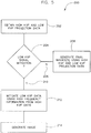
- Technique 200 includes acquiring high and low kVp projection data or datasets at step 202 using, for instance, generator 29 of FIG. 2 to energize source 14, and determining at step 204 whether to apply a low kVp signal mitigation or correction step, according to embodiments of the invention.
- the determination at step 204 may be objectively based on a low signal threshold (LST) value, system characteristics, image acquisition settings, and the like.
- LST low signal threshold
- the determination at step 204 may be subjectively based on a user observation when, for instance, streaking or other artifacts are observed in final images.
- a dual-energy image is generated at step 214 using the acquired high kVp projection data and the adjusted low kVp projection data, according to known methods for dual-energy image reconstruction.
- high frequency resolutions patterns are extracted from high kVp projections and added to acquired low kVp projections, according to embodiments of the invention.
- low kVp signal resolution is enhanced or mitigated by using neighboring high kVp projection data.
- channels of low kVp projections are assessed against an LST and, if one or more channels is below the LST, then adjacent high kVp projections are combined and a high frequency component is extracted therefrom.
- the LST is defined as a point wherein low signal corruption begins, and may be empirically determined relative to a basis phantom and based on operating conditions. For instance, the LST may be determined based on one or more parameters such as a number of views per rotation, focal spot wobble, gantry rotation period, geometric efficiency, component geometry (i.e., source, detector, etc.), detector light output, DAS efficiency, DAS electronic noise, kVp, mA, or the like.
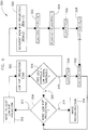
- FIG. 6 represents a loop 300 for low kVp data mitigation that begins at step 302, where a low kVp projection is identified for possible mitigation.
- channels of the identified low kVp projection are assessed against an LST. If not below the LST 306, then a query is made at step 308 as to whether more low kVp datasets should be assessed. If so 310, then the next low kVp projection dataset is considered at step 312. However, if all low kVp projections have been assessed and there are none remaining for consideration 314, then an image is reconstructed using high kVp data and the mitigated low kVp data at step 316 as discussed with respect to FIG. 5 at step 214.
- Low kVp data may be mitigated as further illustrated in FIG. 6 .
- the low kVp projection dataset is corrected, using high frequency data extracted from the high kVp projection data H(n), according to an embodiment of the invention.
- H(n-1) and H(n+1) are determined at step 320 that are adjacent to the low kVp projection data L(n) that is to be mitigated.
- averaging typically includes simple averaging of data, whereas a weighted average includes averaging data with non-equal weighting, as is understood in the art. In other words, as is understood in the art, some data may be weighted more than others. However and regardless, both weighted and non-weighted averaging are included within embodiments of the invention and are encompassed when referring to any type of averaging.
- Scaling factor Sf(n) may be determined by a variety of methods, and will be further illustrated below, according to embodiments of the invention.
- a filtered high kVp projection H sm (n) is formed at step 326 by filtering out high frequency components from the scaled high kVp projection, H s (n).
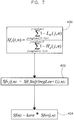
- High frequencies are extracted at step 328 from the scaled high kVp projection, H s (n) by subtracting the filtered high kVp projection H sm (n) therefrom, to form a high frequency projection H ⁇ (n):
- H ⁇ n H s n ⁇ H sm n ;
- scaling factor Sf(n) is determined over a local bin or sub-region.
- a method of determining scaling factor Sf(n) includes calculating a local scale factor for regions of channel bins (for example 75 wide), and creating a channel dependent scale factor vector and low pass filtering the scale factor vector (for example with a 150 point wide hanning kernel). The example is based on a 71 channel single dimensional low pass signal correction filter.
- a local region scaling factor Sf r is determined for regions of channel bins, a channel dependent scale factor having constant values is created in accordance with Sf r (j,n) within each sub-region bin at step 402, and the scale factor is low pass filtered at step 404 using, for instance, a 50 point hanning kernel.
- high and low kVp projection data may be obtained in such a fashion that may reduce the need to mitigate the acquired data using either a conventional or known low signal mitigation scheme, or by using a scheme such as is illustrated in FIG. 5 above.
- high and low kVp projection data may be acquired in asymmetric sampling intervals such that the low kVp integration period is greater than the high kVp integration period.
- a generator such as generator 29 of FIGS. 1 and 2 , may be configured to output low and high kVp 450.
- Low kVp 452 is output for a first period 454, and high kVp 456 is output for a second period 458.
- first period 454 occurs for a time period that is greater than second time period 458.
- Actual or achieved kVp output includes resulting fall times 468 and rise times 470 due to the capacitance of the system and other known effects.
- low and high kVp integration includes low kVp integration periods 474 and high kVp integration periods 476, which are caused to trigger in conjunction with switching from low kVp to high kVp, and vice versa.
- integration of the low kVp signal occurs for a time period that is greater than a time period of integration of the high kVp signal.
- This allows more x-ray photons to be captured and integrated per sample, thereby increasing the desired detected signal above, for instance, electronic noise.
- improvement may be realized by asymmetrically combining fixed trigger intervals.
- data may be sequentially and symmetrically acquired during, for instance, three fixed sample intervals at low kVp and then sequentially during two fixed sample intervals at high kVp.
- low and high kVp integration periods 474, 476 include asymmetrically acquired data, as will be discussed. It is to be understood that signal and cost optimization may be realized by combining embodiments and assessing tradeoffs accordingly.
- total low kVp integration may be set for a time period that exceeds high kVp integration, but such may include symmetrically acquired data, as will be described below.
- the noise benefit of extended integration at low kVp may be offset to an extent by symmetrically obtaining such data.
- embodiments of the invention include weighting the acquired projection data to account for the corresponding locations of the gantry, as understood in the art. For instance, when determining neighboring high kVp projection data at step 320, and subsequently averaging the acquired data as described with respect to Eqn. 1 above, then Eqn. 1 is appropriately modified by weighting the neighboring high kVp projections H(n-1) and H(n+1) to account for the asymmetry of the acquired data. Further, one skilled in the art will recognize that multiple neighboring high kVp projections may be used to obtain the average or weighted average high kVp projection H a (n) at step 322.
- Yet another method that can be used independently or in conjunction with any of the disclosed methods and techniques herein is to increase the low kVp integration interval by decreasing the number of projections. This can be done while taking into account and optimizing for azimuthal resolution loss and view aliasing.
- orthogonal scan projection data is acquired for both lateral and anterior-posterior (AP) scout scans. After accounting for bowtie attenuation, for each Z-width covered per rotation, view averages may be obtained and separated into center and edge zones.
- a projection measure (PM) (attenuation in terms normalized to water) is compared to a low signal threshold (LST) that is a function of operating conditions for the scanner.
- LST low signal threshold
- patient attenuation and LST can be stated directly in terms of pre-log signal intensity or by using post log PM and LST.
- LST-PM can be determined for respective lateral and AP views and, if a LST-PM is below a set limit, then a reduced view rate in corresponding sections or views may be used.
- low kVp data is a general terminology to describe the projection dataset having worse statistics during a dual energy acquisition.
- additional filtration can be applied to the high kVp tube-detector (e.g., additional Sn filter for 140kVp setting) and increased low kVp for the other tube-detector pair (e.g., increase from 80kVp to 100kVp).
- the dataset with lower kVp setting 100kVp
- the correction approach outlined above is applied to the higher kVp setting (140kVp) instead of the lower kVp setting (100kVp).
- nearby channels from k-n to k+n of the "high kVp” data may be used to perform a polynomial fit of the "low kVp" data from k-n to k+n to obtain an estimation of "low kVp" channel k with a fitted "high kVp” channel k.
- filtration parameters e.g., both high-pass and low-pass described in FIG. 6
- filtration parameters can be changed dynamically dependent on measured projection data.
- package/baggage inspection system 510 includes a rotatable gantry 512 having an opening 514 therein through which packages or pieces of baggage may pass.
- the rotatable gantry 512 houses a high frequency electromagnetic energy source 516 as well as a detector assembly 518 having scintillator arrays comprised of scintillator cells similar to that shown in FIG. 4 .
- a conveyor system 520 also is provided and includes a conveyor belt 522 supported by structure 524 to automatically and continuously pass packages or baggage pieces 526 through opening 514 to be scanned. Objects 526 are fed through opening 514 by conveyor belt 522, imaging data is then acquired, and the conveyor belt 522 removes the packages 526 from opening 514 in a controlled and continuous manner.
- postal inspectors, baggage handlers, and other security personnel may non-invasively inspect the contents of packages 526 for explosives, knives, guns, contraband, etc.
- multi-energy data may be acquired during symmetric or asymmetric sampling intervals.
- view data may be symmetrically acquired and combined to generate imaging data at a given kVp.
- an integration period may be divided into three symmetric windows ( FIG. 10 ) or into two symmetric windows ( FIG. 11 ), as examples.
- electronic noise (En) compounds proportionally to the square root of the number of view datasets that are being combined: Noise ⁇ # views ⁇ En ;
- an integration period includes a combination of three view datasets
- electronic noise during this integration period is compounded by a factor of 3 , which equals approximately 1.7.
- any integration period includes a combination of two view datasets
- electronic noise during this integration period is compounded by a factor of 2 , which is approximately 1.4.
- the symmetric intervals will be described and illustrated with respect to FIGS. 10 and 11 .
- an integration period 550 is a period for image data integration that may correspond to, for instance, low kVp integration period 474 or high kVp integration period 476 of FIG. 8 .
- the total electronic noise N is thus approximately 1.7 times the electronic noise or approximately 1.7 X En.
- image data may be acquired asymmetrically, according to embodiments of the invention. That is, a single set of view data may be obtained or sampled during integration period 550. Alternatively, data may be sampled or integrated in a symmetric arrangement. In a symmetric arrangement, view data may be acquired during three distinct and symmetric view windows 552. Each set of view data includes a corresponding level of electronic noise En.
- an integration period 554 may correspond to low kVp integration period 474 or high kVp integration period 476, as illustrated in FIG. 8 .
- total electronic noise N is thus approximately 1.4 times the electronic noise, thus equals approximately 1.4 X En.
- image data may be acquired asymmetrically, according to the invention. That is, a single set of view data may be obtained or sampled during a low kVp integration period that may correspond to, for instance, low kVp integration period 474 or high kVp integration period 476 of FIG. 8 .
- Integration period 554 may be integrated in a symmetrical arrangement or an asymmetric arrangement, both of which are illustrated for discussion purposes.
- view data may be acquired during two distinct view windows 556.
- Each view dataset includes a corresponding level of electronic noise En.
- a single set of view data may be asymmetrically acquired by integrating imaging signals for each respective low kVp and high kVp period.
- embodiments of the invention may include symmetrically acquiring data during, for instance, a high kVp integration period, and asymmetrically acquiring data during a low kVp integration period.
- a longer integration period may affect image resolution to an extent when obtaining CT data.
- the image resolution may play a secondary role when considered against image noise.
- asymmetric integration intervals may be selected by optimizing between image noise and image resolution.
- a low kVp signal may range from 3-8 times less than a high kVp signal, hence a low kVp integration period may be 3-8 times greater than a high kVp integration period.
- integration intervals typically include integration during fall times and rise times, such as fall times 468 and rise times 470 as discussed with respect to FIG. 8 .
- low kVp integration period 474 includes fall time 468
- high kVp integration period 476 includes rise time 470.
- integration during fall and rise times can negatively impact image noise, and it may be desirable to selectively integrate one or both having extended portions of the fall and rise times during, for instance, the high kVp integration periods.
- SNR tends to be higher during a high kVp period as compared to a low kVp period
- trigger points for high kVp and low kVp integration periods may be triggered independently to best optimize noise against, for instance, image resolution.
- the trigger points may be selected by determining an amount of skew between a trigger point of a kVp to be applied and a trigger point for acquiring view data.
- an amount of rise time skew and fall time skew may be selected based on characteristics of a generator.
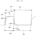
- FIG. 12 illustrates a first pair of high and low kVp applications and represents a repeating pattern of high and low kVp shots as illustrated in FIG. 8 .
- a low kVp is output for a first period 454, and a high kVp is output for a second period 458.
- second period 458 begins at the start of a voltage rise time 470 and ends at the start of a voltage fall time 468.
- First period 454 begins at the start of voltage fall time 468 and ends at the start of the next voltage rise time 470.
- the high and low kVp voltages stabilize to steady state after their respective voltage rise time or fall time 470, 468.
- Low and high kVp signals may be integrated during respective periods 474, 476.
- low and high kVp integration periods 474, 476 in FIG. 12 may be skewed or offset from the start of rise time 470 and fall time 468 in order to have the noise of the fall and rise times that corresponds to the high kVp be included in the high kVp integrated signal, in one example.
- triggering the low and high integration periods 474, 476 may be offset the same amount of time from trigger points where respective low and high kVp is applied via the generator.
- the low and high integration periods 474, 476 may be separately controllable by effectively separately controlling a rise time lag or skew period 558 (skew R) and a fall time lag or skew period 560 (skew F), as illustrated.
- skew R 558 is set to zero, thus noise associated with rise time 470 is preferably included in the high kVp integration data.
- both skew R 558 and skew F 560 may be separately controlled in a fashion that minimizes overall noise, according to embodiments of the invention.
- data may be asymmetrically obtained in order to minimize overall noise during an integration period.
- skews during rise and fall times may be selectively and individually controlled in order that noise associated therewith may be preferentially included in the high kVp integration data, according to one embodiment.
- the skews may be iterated upon, as understood in the art, to optimize noise performance in acquired data and to optimize and balance competing factors that may include noise, resolution, and energy separation, as examples.
- An implementation of embodiments of the invention in an example comprises a plurality of components such as one or more of electronic components, hardware components, and/or computer software components. A number of such components can be combined or divided in an implementation of the embodiments of the invention.
- An exemplary component of an implementation of the embodiments of the invention employs and/or comprises a set and/or series of computer instructions written in or implemented with any of a number of programming languages, as will be appreciated by those skilled in the art.
- An implementation of the embodiments of the invention in an example employs one or more computer readable storage media.
- An example of a computer-readable signal-bearing medium for an implementation of the embodiments of the invention comprises the recordable data storage medium of the image reconstructor 34, and/or the mass storage device 38 of the computer 36.
- a computer-readable storage medium for an implementation of the embodiments of the invention in an example comprises one or more of a magnetic, electrical, optical, biological, and/or atomic data storage medium.
- an implementation of the computer-readable signal-bearing medium comprises floppy disks, magnetic tapes, CD-ROMs, DVD-ROMs, hard disk drives, and/or electronic memory.
- a technical contribution for various of the disclosed methods and apparatus is that it provides for a computer-implemented apparatus and method of acquiring imaging data at more than one energy range using a multi-energy imaging source.
- a CT system includes a rotatable gantry having an opening for receiving an object to be scanned, and a controller configured to apply a first kVp for a first time period, apply a second kVp for a second time period, wherein the second time period is different from the first time period, acquire a first asymmetric view dataset during at least a portion of the first time period, acquire a second asymmetric view dataset during at least a portion of the second time period, and generate an image using the acquired first and second asymmetric view datasets.
- a method of imaging includes selecting a rise time skew period based on characteristics of a generator, selecting a fall time skew period, different from the rise time skew period, based on characteristics of the generator, triggering acquisition of a low kVp dataset during a first timeframe and based on the fall time skew period, triggering acquisition of a high kVp dataset during a second timeframe and based on the rise time skew period, wherein the first timeframe is a time duration that is greater than a time duration of the second timeframe, and generating an image using at least the acquired low kVp dataset and the acquired high kVp dataset.
- a computer readable storage medium having a computer program stored thereon and representing a set of instructions that when executed by a computer causes the computer to optimize an energy separation between imaging data to be acquired at a first energy level and imaging data to be acquired at a second energy level, the optimization based on a rise time characteristic and a fall time characteristic of a generator, acquire a first view of imaging data for at least a portion of a first time period while the first energy level is applied to an imaging source by the generator, acquire a second view of imaging data for at least a portion of a second time period while the second energy level is applied to the imaging source by the generator, and generate an image using the acquired first view of imaging data and the acquired second view of imaging data.
Landscapes
- Health & Medical Sciences (AREA)
- Life Sciences & Earth Sciences (AREA)
- Engineering & Computer Science (AREA)
- Medical Informatics (AREA)
- Radiology & Medical Imaging (AREA)
- Biomedical Technology (AREA)
- Biophysics (AREA)
- High Energy & Nuclear Physics (AREA)
- Veterinary Medicine (AREA)
- Nuclear Medicine, Radiotherapy & Molecular Imaging (AREA)
- Optics & Photonics (AREA)
- Pathology (AREA)
- Public Health (AREA)
- Physics & Mathematics (AREA)
- Heart & Thoracic Surgery (AREA)
- Molecular Biology (AREA)
- Surgery (AREA)
- Animal Behavior & Ethology (AREA)
- General Health & Medical Sciences (AREA)
- Pulmonology (AREA)
- Theoretical Computer Science (AREA)
- Computer Vision & Pattern Recognition (AREA)
- Apparatus For Radiation Diagnosis (AREA)
- Analysing Materials By The Use Of Radiation (AREA)
Applications Claiming Priority (1)
| Application Number | Priority Date | Filing Date | Title |
|---|---|---|---|
| US12/760,862 US8199875B2 (en) | 2009-12-11 | 2010-04-15 | System and method of acquiring multi-energy CT imaging data |
Publications (2)
| Publication Number | Publication Date |
|---|---|
| EP2377468A1 EP2377468A1 (en) | 2011-10-19 |
| EP2377468B1 true EP2377468B1 (en) | 2020-04-01 |
Family
ID=44201924
Family Applications (1)
| Application Number | Title | Priority Date | Filing Date |
|---|---|---|---|
| EP11161801.3A Active EP2377468B1 (en) | 2010-04-15 | 2011-04-11 | System of acquiring multi-energy CT imaging data |
Country Status (4)
| Country | Link |
|---|---|
| US (2) | US8199875B2 (enExample) |
| EP (1) | EP2377468B1 (enExample) |
| JP (1) | JP5763916B2 (enExample) |
| CN (2) | CN102217947B (enExample) |
Families Citing this family (26)
| Publication number | Priority date | Publication date | Assignee | Title |
|---|---|---|---|---|
| WO2010144094A1 (en) * | 2009-06-12 | 2010-12-16 | Analogic Corporation | Correction for source switching in multi energy scanner |
| US8199874B2 (en) * | 2009-12-11 | 2012-06-12 | General Electric Company | System and method of mitigating low signal data for dual energy CT |
| WO2013122763A1 (en) * | 2012-02-14 | 2013-08-22 | American Science And Engineering, Inc. | X-ray inspection using wavelength-shifting fiber-coupled scintillation detectors |
| DE102012222714A1 (de) * | 2012-12-11 | 2014-06-12 | Siemens Aktiengesellschaft | Ermittlung eines Mehrfachenergie-Bildes |
| KR20140092438A (ko) * | 2012-12-27 | 2014-07-24 | 삼성전자주식회사 | 엑스선 검출 패널, 엑스선 촬영 장치 및 엑스선 영상 생성 방법 |
| CN103892859A (zh) * | 2012-12-28 | 2014-07-02 | Ge医疗系统环球技术有限公司 | 基于多模式Scout扫描的CT成像方法和CT系统 |
| JP6325256B2 (ja) * | 2013-01-07 | 2018-05-16 | キヤノンメディカルシステムズ株式会社 | X線コンピュータ断層撮影装置及び医用画像処理装置 |
| DE102013206075B4 (de) * | 2013-04-05 | 2021-11-11 | Siemens Healthcare Gmbh | Verfahren zur Korrektur einer Signalverteilung sowie Verfahren und Tomographiegerät zur Reduktion von Bildartefakten |
| CN103190926A (zh) * | 2013-04-12 | 2013-07-10 | 王宝良 | X光机立体成像装置及成像方法 |
| GB201308876D0 (en) | 2013-05-16 | 2013-07-03 | Ibex Innovations Ltd | X-Ray imaging apparatus and methods |
| GB201308851D0 (en) | 2013-05-16 | 2013-07-03 | Ibex Innovations Ltd | Multi-spectral x-ray detection apparatus |
| GB201308818D0 (en) | 2013-05-16 | 2013-07-03 | Ibex Innovations Ltd | X-ray detector apparatus |
| US8965095B2 (en) * | 2013-05-30 | 2015-02-24 | Kabushiki Kaisha Toshiba | Noise balance pre-reconstruction data decomposition in spectral CT |
| DE102013218692B4 (de) | 2013-09-18 | 2022-09-08 | Siemens Healthcare Gmbh | Detektion von Röntgenstrahlung |
| US9320481B2 (en) | 2014-03-31 | 2016-04-26 | General Electric Company | Systems and methods for X-ray imaging |
| JP6523825B2 (ja) * | 2014-07-02 | 2019-06-05 | キヤノンメディカルシステムズ株式会社 | X線ct装置及び画像処理装置 |
| WO2016059527A2 (en) | 2014-10-13 | 2016-04-21 | Koninklijke Philips N.V. | Spectral imaging |
| WO2017019554A1 (en) * | 2015-07-24 | 2017-02-02 | Photo Diagnostic Systems, Inc. | Method and apparatus for performing multi-energy (including dual energy) computed tomography (ct) imaging |
| CA2998364A1 (en) | 2015-09-10 | 2017-03-16 | American Science And Engineering, Inc. | Backscatter characterization using interlinearly adaptive electromagnetic x-ray scanning |
| US10165996B2 (en) * | 2015-09-30 | 2019-01-01 | General Electric Company | Systems and methods for dual-energy computed tomography imaging |
| US10646176B2 (en) * | 2015-09-30 | 2020-05-12 | General Electric Company | Layered radiation detector |
| US10573030B2 (en) | 2017-04-07 | 2020-02-25 | Photo Diagnostic Systems, Inc. | Method for artifact reduction using monoenergetic data in computed tomography |
| WO2020002174A1 (en) * | 2018-06-29 | 2020-01-02 | Koninklijke Philips N.V. | Imaging system configured to generate non-spectral volumetric image data from a kvp switching multi-energy acquisition |
| JP7490333B2 (ja) * | 2018-12-17 | 2024-05-27 | キヤノンメディカルシステムズ株式会社 | X線ctシステム及び処理プログラム |
| US11193898B1 (en) | 2020-06-01 | 2021-12-07 | American Science And Engineering, Inc. | Systems and methods for controlling image contrast in an X-ray system |
| CN112712572B (zh) * | 2021-01-11 | 2023-10-24 | 明峰医疗系统股份有限公司 | Ct扫描设备的低信号噪声的抑制方法、系统及计算机可读存储介质 |
Family Cites Families (23)
| Publication number | Priority date | Publication date | Assignee | Title |
|---|---|---|---|---|
| US4541106A (en) * | 1984-02-22 | 1985-09-10 | General Electric Company | Dual energy rapid switching imaging system |
| US4780897A (en) * | 1986-05-06 | 1988-10-25 | General Electric Company | Dual energy imaging with kinestatic charge detector |
| US6343112B1 (en) * | 2000-12-14 | 2002-01-29 | Ge Medical Systems Global Technology Company, Llc | Method and apparatus for reducing photoconductive effects in dual energy applications of solid state digital X-ray detectors |
| US6393097B1 (en) * | 2000-12-22 | 2002-05-21 | Ge Medical Systems Global Technology Company, Llc | Digital detector method for dual energy imaging |
| US6621887B2 (en) * | 2001-10-15 | 2003-09-16 | General Electric Company | Method and apparatus for processing a fluoroscopic image |
| JP2003144427A (ja) * | 2001-11-06 | 2003-05-20 | Ge Medical Systems Global Technology Co Llc | X線ctシステム、操作コンソールおよびその制御方法、ならびにプログラム |
| US6931098B2 (en) * | 2002-03-08 | 2005-08-16 | Ge Medical Systems Global Technology Company, Llc | Method and system for dual or multiple energy imaging |
| US7272429B2 (en) * | 2002-11-27 | 2007-09-18 | Ge Medical Systems Global Technology Company, Llc | Methods and apparatus for facilitating a reduction in artifacts |
| US7616799B2 (en) * | 2004-06-18 | 2009-11-10 | Siemens Medical Solutions Usa, Inc. | System and method for monitoring disease progression or response to therapy using multi-modal visualization |
| DE102004063995A1 (de) * | 2004-10-25 | 2006-08-17 | Siemens Ag | Tomographiegerät und Verfahren für ein Tomographiegerät zur Erzeugung von Mehrfachenergie-Bildern |
| US7054407B1 (en) | 2005-02-08 | 2006-05-30 | General Electric Company | Methods and apparatus to facilitate reconstruction of images |
| JP5058517B2 (ja) | 2005-06-14 | 2012-10-24 | キヤノン株式会社 | 放射線撮像装置及びその制御方法並びに放射線撮像システム |
| CN100471453C (zh) * | 2005-06-14 | 2009-03-25 | 佳能株式会社 | 放射线成像装置、其控制方法和放射线成像系统 |
| CN101370430A (zh) * | 2006-01-24 | 2009-02-18 | 株式会社岛津制作所 | X射线摄像装置 |
| DE102006014624B4 (de) * | 2006-03-29 | 2008-04-10 | Siemens Ag | Verfahren zur Aufnahme von Projektionsbildern |
| JP5389324B2 (ja) * | 2006-12-18 | 2014-01-15 | ジーイー・メディカル・システムズ・グローバル・テクノロジー・カンパニー・エルエルシー | X線断層撮影装置 |
| JP5248031B2 (ja) * | 2007-04-23 | 2013-07-31 | ジーイー・メディカル・システムズ・グローバル・テクノロジー・カンパニー・エルエルシー | X線ct装置 |
| JP2008279153A (ja) * | 2007-05-14 | 2008-11-20 | Ge Medical Systems Global Technology Co Llc | X線ct装置 |
| JP5106978B2 (ja) | 2007-10-15 | 2012-12-26 | ジーイー・メディカル・システムズ・グローバル・テクノロジー・カンパニー・エルエルシー | X線ct装置 |
| JP5229865B2 (ja) * | 2007-11-30 | 2013-07-03 | ジーイー・メディカル・システムズ・グローバル・テクノロジー・カンパニー・エルエルシー | X線ct装置 |
| JP5179268B2 (ja) * | 2008-06-17 | 2013-04-10 | ジーイー・メディカル・システムズ・グローバル・テクノロジー・カンパニー・エルエルシー | X線ct装置 |
| JP5405229B2 (ja) * | 2008-08-11 | 2014-02-05 | 株式会社東芝 | X線コンピュータ断層撮影装置 |
| US7995702B2 (en) * | 2009-08-25 | 2011-08-09 | General Electric Company | System and method of data interpolation in fast kVp switching dual energy CT |
-
2010
- 2010-04-15 US US12/760,862 patent/US8199875B2/en active Active
- 2010-12-20 JP JP2010282501A patent/JP5763916B2/ja active Active
- 2010-12-27 CN CN201010625184.2A patent/CN102217947B/zh active Active
- 2010-12-27 CN CN201610239910.4A patent/CN105943069B/zh active Active
-
2011
- 2011-04-11 EP EP11161801.3A patent/EP2377468B1/en active Active
-
2012
- 2012-05-31 US US13/484,707 patent/US8363779B2/en active Active
Non-Patent Citations (1)
| Title |
|---|
| None * |
Also Published As
| Publication number | Publication date |
|---|---|
| US8363779B2 (en) | 2013-01-29 |
| JP2011224341A (ja) | 2011-11-10 |
| US20120236984A1 (en) | 2012-09-20 |
| CN105943069B (zh) | 2019-07-12 |
| JP5763916B2 (ja) | 2015-08-12 |
| CN102217947A (zh) | 2011-10-19 |
| CN105943069A (zh) | 2016-09-21 |
| CN102217947B (zh) | 2016-05-18 |
| EP2377468A1 (en) | 2011-10-19 |
| US20110142194A1 (en) | 2011-06-16 |
| US8199875B2 (en) | 2012-06-12 |
Similar Documents
| Publication | Publication Date | Title |
|---|---|---|
| EP2377468B1 (en) | System of acquiring multi-energy CT imaging data | |
| US8199874B2 (en) | System and method of mitigating low signal data for dual energy CT | |
| US7826587B1 (en) | System and method of fast kVp switching for dual energy CT | |
| US9135728B2 (en) | System and method for multi-energy computed tomography imaging | |
| US7792241B2 (en) | System and method of fast KVP switching for dual energy CT | |
| US7724865B2 (en) | System and method of optimizing a monochromatic representation of basis material decomposed CT images | |
| EP2296551B1 (en) | Spectral ct | |
| US8315352B2 (en) | System and method of spectral calibration and basis material decomposition for X-ray CT systems | |
| US7813474B2 (en) | Method and apparatus for performing dual-spectrum CT with fast KV modulation at multiple-view intervals | |
| US7852979B2 (en) | Dual-focus X-ray tube for resolution enhancement and energy sensitive CT | |
| US8363917B2 (en) | System and method of image artifact reduction in fast kVp switching CT | |
| US9320477B2 (en) | Method and apparatus for adaptive scatter correction | |
| US8488854B2 (en) | System and apparatus for classifying x-ray energy into discrete levels | |
| EP2370836B1 (en) | Spectral imaging | |
| US8548118B2 (en) | Apparatus and method for spectral projection imaging with fast KV switching |
Legal Events
| Date | Code | Title | Description |
|---|---|---|---|
| AK | Designated contracting states |
Kind code of ref document: A1 Designated state(s): AL AT BE BG CH CY CZ DE DK EE ES FI FR GB GR HR HU IE IS IT LI LT LU LV MC MK MT NL NO PL PT RO RS SE SI SK SM TR |
|
| AX | Request for extension of the european patent |
Extension state: BA ME |
|
| PUAI | Public reference made under article 153(3) epc to a published international application that has entered the european phase |
Free format text: ORIGINAL CODE: 0009012 |
|
| 17P | Request for examination filed |
Effective date: 20120419 |
|
| 17Q | First examination report despatched |
Effective date: 20150317 |
|
| STAA | Information on the status of an ep patent application or granted ep patent |
Free format text: STATUS: EXAMINATION IS IN PROGRESS |
|
| RIC1 | Information provided on ipc code assigned before grant |
Ipc: A61B 6/03 20060101AFI20190529BHEP Ipc: A61B 6/00 20060101ALI20190529BHEP |
|
| GRAP | Despatch of communication of intention to grant a patent |
Free format text: ORIGINAL CODE: EPIDOSNIGR1 |
|
| STAA | Information on the status of an ep patent application or granted ep patent |
Free format text: STATUS: GRANT OF PATENT IS INTENDED |
|
| INTG | Intention to grant announced |
Effective date: 20190725 |
|
| GRAJ | Information related to disapproval of communication of intention to grant by the applicant or resumption of examination proceedings by the epo deleted |
Free format text: ORIGINAL CODE: EPIDOSDIGR1 |
|
| STAA | Information on the status of an ep patent application or granted ep patent |
Free format text: STATUS: EXAMINATION IS IN PROGRESS |
|
| GRAP | Despatch of communication of intention to grant a patent |
Free format text: ORIGINAL CODE: EPIDOSNIGR1 |
|
| STAA | Information on the status of an ep patent application or granted ep patent |
Free format text: STATUS: GRANT OF PATENT IS INTENDED |
|
| INTC | Intention to grant announced (deleted) | ||
| INTG | Intention to grant announced |
Effective date: 20191121 |
|
| GRAS | Grant fee paid |
Free format text: ORIGINAL CODE: EPIDOSNIGR3 |
|
| GRAA | (expected) grant |
Free format text: ORIGINAL CODE: 0009210 |
|
| STAA | Information on the status of an ep patent application or granted ep patent |
Free format text: STATUS: THE PATENT HAS BEEN GRANTED |
|
| AK | Designated contracting states |
Kind code of ref document: B1 Designated state(s): AL AT BE BG CH CY CZ DE DK EE ES FI FR GB GR HR HU IE IS IT LI LT LU LV MC MK MT NL NO PL PT RO RS SE SI SK SM TR |
|
| REG | Reference to a national code |
Ref country code: GB Ref legal event code: FG4D |
|
| REG | Reference to a national code |
Ref country code: AT Ref legal event code: REF Ref document number: 1250300 Country of ref document: AT Kind code of ref document: T Effective date: 20200415 Ref country code: CH Ref legal event code: EP |
|
| REG | Reference to a national code |
Ref country code: DE Ref legal event code: R096 Ref document number: 602011065935 Country of ref document: DE |
|
| REG | Reference to a national code |
Ref country code: IE Ref legal event code: FG4D |
|
| PG25 | Lapsed in a contracting state [announced via postgrant information from national office to epo] |
Ref country code: BG Free format text: LAPSE BECAUSE OF FAILURE TO SUBMIT A TRANSLATION OF THE DESCRIPTION OR TO PAY THE FEE WITHIN THE PRESCRIBED TIME-LIMIT Effective date: 20200701 |
|
| REG | Reference to a national code |
Ref country code: NL Ref legal event code: MP Effective date: 20200401 |
|
| REG | Reference to a national code |
Ref country code: LT Ref legal event code: MG4D |
|
| PG25 | Lapsed in a contracting state [announced via postgrant information from national office to epo] |
Ref country code: PT Free format text: LAPSE BECAUSE OF FAILURE TO SUBMIT A TRANSLATION OF THE DESCRIPTION OR TO PAY THE FEE WITHIN THE PRESCRIBED TIME-LIMIT Effective date: 20200817 Ref country code: FI Free format text: LAPSE BECAUSE OF FAILURE TO SUBMIT A TRANSLATION OF THE DESCRIPTION OR TO PAY THE FEE WITHIN THE PRESCRIBED TIME-LIMIT Effective date: 20200401 Ref country code: CZ Free format text: LAPSE BECAUSE OF FAILURE TO SUBMIT A TRANSLATION OF THE DESCRIPTION OR TO PAY THE FEE WITHIN THE PRESCRIBED TIME-LIMIT Effective date: 20200401 Ref country code: NO Free format text: LAPSE BECAUSE OF FAILURE TO SUBMIT A TRANSLATION OF THE DESCRIPTION OR TO PAY THE FEE WITHIN THE PRESCRIBED TIME-LIMIT Effective date: 20200701 Ref country code: IS Free format text: LAPSE BECAUSE OF FAILURE TO SUBMIT A TRANSLATION OF THE DESCRIPTION OR TO PAY THE FEE WITHIN THE PRESCRIBED TIME-LIMIT Effective date: 20200801 Ref country code: GR Free format text: LAPSE BECAUSE OF FAILURE TO SUBMIT A TRANSLATION OF THE DESCRIPTION OR TO PAY THE FEE WITHIN THE PRESCRIBED TIME-LIMIT Effective date: 20200702 Ref country code: LT Free format text: LAPSE BECAUSE OF FAILURE TO SUBMIT A TRANSLATION OF THE DESCRIPTION OR TO PAY THE FEE WITHIN THE PRESCRIBED TIME-LIMIT Effective date: 20200401 Ref country code: NL Free format text: LAPSE BECAUSE OF FAILURE TO SUBMIT A TRANSLATION OF THE DESCRIPTION OR TO PAY THE FEE WITHIN THE PRESCRIBED TIME-LIMIT Effective date: 20200401 Ref country code: SE Free format text: LAPSE BECAUSE OF FAILURE TO SUBMIT A TRANSLATION OF THE DESCRIPTION OR TO PAY THE FEE WITHIN THE PRESCRIBED TIME-LIMIT Effective date: 20200401 |
|
| REG | Reference to a national code |
Ref country code: AT Ref legal event code: MK05 Ref document number: 1250300 Country of ref document: AT Kind code of ref document: T Effective date: 20200401 |
|
| PG25 | Lapsed in a contracting state [announced via postgrant information from national office to epo] |
Ref country code: LV Free format text: LAPSE BECAUSE OF FAILURE TO SUBMIT A TRANSLATION OF THE DESCRIPTION OR TO PAY THE FEE WITHIN THE PRESCRIBED TIME-LIMIT Effective date: 20200401 Ref country code: HR Free format text: LAPSE BECAUSE OF FAILURE TO SUBMIT A TRANSLATION OF THE DESCRIPTION OR TO PAY THE FEE WITHIN THE PRESCRIBED TIME-LIMIT Effective date: 20200401 Ref country code: RS Free format text: LAPSE BECAUSE OF FAILURE TO SUBMIT A TRANSLATION OF THE DESCRIPTION OR TO PAY THE FEE WITHIN THE PRESCRIBED TIME-LIMIT Effective date: 20200401 |
|
| REG | Reference to a national code |
Ref country code: CH Ref legal event code: PL |
|
| PG25 | Lapsed in a contracting state [announced via postgrant information from national office to epo] |
Ref country code: AL Free format text: LAPSE BECAUSE OF FAILURE TO SUBMIT A TRANSLATION OF THE DESCRIPTION OR TO PAY THE FEE WITHIN THE PRESCRIBED TIME-LIMIT Effective date: 20200401 |
|
| REG | Reference to a national code |
Ref country code: DE Ref legal event code: R097 Ref document number: 602011065935 Country of ref document: DE |
|
| PG25 | Lapsed in a contracting state [announced via postgrant information from national office to epo] |
Ref country code: EE Free format text: LAPSE BECAUSE OF FAILURE TO SUBMIT A TRANSLATION OF THE DESCRIPTION OR TO PAY THE FEE WITHIN THE PRESCRIBED TIME-LIMIT Effective date: 20200401 Ref country code: LI Free format text: LAPSE BECAUSE OF NON-PAYMENT OF DUE FEES Effective date: 20200430 Ref country code: SM Free format text: LAPSE BECAUSE OF FAILURE TO SUBMIT A TRANSLATION OF THE DESCRIPTION OR TO PAY THE FEE WITHIN THE PRESCRIBED TIME-LIMIT Effective date: 20200401 Ref country code: LU Free format text: LAPSE BECAUSE OF NON-PAYMENT OF DUE FEES Effective date: 20200411 Ref country code: DK Free format text: LAPSE BECAUSE OF FAILURE TO SUBMIT A TRANSLATION OF THE DESCRIPTION OR TO PAY THE FEE WITHIN THE PRESCRIBED TIME-LIMIT Effective date: 20200401 Ref country code: ES Free format text: LAPSE BECAUSE OF FAILURE TO SUBMIT A TRANSLATION OF THE DESCRIPTION OR TO PAY THE FEE WITHIN THE PRESCRIBED TIME-LIMIT Effective date: 20200401 Ref country code: AT Free format text: LAPSE BECAUSE OF FAILURE TO SUBMIT A TRANSLATION OF THE DESCRIPTION OR TO PAY THE FEE WITHIN THE PRESCRIBED TIME-LIMIT Effective date: 20200401 Ref country code: CH Free format text: LAPSE BECAUSE OF NON-PAYMENT OF DUE FEES Effective date: 20200430 Ref country code: MC Free format text: LAPSE BECAUSE OF FAILURE TO SUBMIT A TRANSLATION OF THE DESCRIPTION OR TO PAY THE FEE WITHIN THE PRESCRIBED TIME-LIMIT Effective date: 20200401 Ref country code: IT Free format text: LAPSE BECAUSE OF FAILURE TO SUBMIT A TRANSLATION OF THE DESCRIPTION OR TO PAY THE FEE WITHIN THE PRESCRIBED TIME-LIMIT Effective date: 20200401 Ref country code: RO Free format text: LAPSE BECAUSE OF FAILURE TO SUBMIT A TRANSLATION OF THE DESCRIPTION OR TO PAY THE FEE WITHIN THE PRESCRIBED TIME-LIMIT Effective date: 20200401 |
|
| REG | Reference to a national code |
Ref country code: BE Ref legal event code: MM Effective date: 20200430 |
|
| PLBE | No opposition filed within time limit |
Free format text: ORIGINAL CODE: 0009261 |
|
| STAA | Information on the status of an ep patent application or granted ep patent |
Free format text: STATUS: NO OPPOSITION FILED WITHIN TIME LIMIT |
|
| PG25 | Lapsed in a contracting state [announced via postgrant information from national office to epo] |
Ref country code: BE Free format text: LAPSE BECAUSE OF NON-PAYMENT OF DUE FEES Effective date: 20200430 Ref country code: PL Free format text: LAPSE BECAUSE OF FAILURE TO SUBMIT A TRANSLATION OF THE DESCRIPTION OR TO PAY THE FEE WITHIN THE PRESCRIBED TIME-LIMIT Effective date: 20200401 Ref country code: SK Free format text: LAPSE BECAUSE OF FAILURE TO SUBMIT A TRANSLATION OF THE DESCRIPTION OR TO PAY THE FEE WITHIN THE PRESCRIBED TIME-LIMIT Effective date: 20200401 |
|
| 26N | No opposition filed |
Effective date: 20210112 |
|
| PG25 | Lapsed in a contracting state [announced via postgrant information from national office to epo] |
Ref country code: IE Free format text: LAPSE BECAUSE OF NON-PAYMENT OF DUE FEES Effective date: 20200411 Ref country code: FR Free format text: LAPSE BECAUSE OF NON-PAYMENT OF DUE FEES Effective date: 20200601 |
|
| PG25 | Lapsed in a contracting state [announced via postgrant information from national office to epo] |
Ref country code: SI Free format text: LAPSE BECAUSE OF FAILURE TO SUBMIT A TRANSLATION OF THE DESCRIPTION OR TO PAY THE FEE WITHIN THE PRESCRIBED TIME-LIMIT Effective date: 20200401 |
|
| PG25 | Lapsed in a contracting state [announced via postgrant information from national office to epo] |
Ref country code: TR Free format text: LAPSE BECAUSE OF FAILURE TO SUBMIT A TRANSLATION OF THE DESCRIPTION OR TO PAY THE FEE WITHIN THE PRESCRIBED TIME-LIMIT Effective date: 20200401 Ref country code: MT Free format text: LAPSE BECAUSE OF FAILURE TO SUBMIT A TRANSLATION OF THE DESCRIPTION OR TO PAY THE FEE WITHIN THE PRESCRIBED TIME-LIMIT Effective date: 20200401 Ref country code: CY Free format text: LAPSE BECAUSE OF FAILURE TO SUBMIT A TRANSLATION OF THE DESCRIPTION OR TO PAY THE FEE WITHIN THE PRESCRIBED TIME-LIMIT Effective date: 20200401 |
|
| PG25 | Lapsed in a contracting state [announced via postgrant information from national office to epo] |
Ref country code: MK Free format text: LAPSE BECAUSE OF FAILURE TO SUBMIT A TRANSLATION OF THE DESCRIPTION OR TO PAY THE FEE WITHIN THE PRESCRIBED TIME-LIMIT Effective date: 20200401 |
|
| P01 | Opt-out of the competence of the unified patent court (upc) registered |
Effective date: 20230528 |
|
| PGFP | Annual fee paid to national office [announced via postgrant information from national office to epo] |
Ref country code: GB Payment date: 20250319 Year of fee payment: 15 |
|
| PGFP | Annual fee paid to national office [announced via postgrant information from national office to epo] |
Ref country code: DE Payment date: 20250319 Year of fee payment: 15 |
|
| REG | Reference to a national code |
Ref country code: DE Ref legal event code: R081 Ref document number: 602011065935 Country of ref document: DE Owner name: GE PRECISION HEALTHCARE LLC, WAUKESHA, US Free format text: FORMER OWNER: GENERAL ELECTRIC COMPANY, SCHENECTADY, NY, US |
|
| REG | Reference to a national code |
Ref country code: GB Ref legal event code: 732E Free format text: REGISTERED BETWEEN 20250807 AND 20250813 |