EP2377425B1 - Dispositif et procédé de fabrication de brosses - Google Patents
Dispositif et procédé de fabrication de brosses Download PDFInfo
- Publication number
- EP2377425B1 EP2377425B1 EP20100003938 EP10003938A EP2377425B1 EP 2377425 B1 EP2377425 B1 EP 2377425B1 EP 20100003938 EP20100003938 EP 20100003938 EP 10003938 A EP10003938 A EP 10003938A EP 2377425 B1 EP2377425 B1 EP 2377425B1
- Authority
- EP
- European Patent Office
- Prior art keywords
- bristles
- base part
- tool
- trimmed
- bristle
- Prior art date
- Legal status (The legal status is an assumption and is not a legal conclusion. Google has not performed a legal analysis and makes no representation as to the accuracy of the status listed.)
- Active
Links
- 238000000034 method Methods 0.000 title claims description 36
- 238000004519 manufacturing process Methods 0.000 title claims description 6
- 238000005520 cutting process Methods 0.000 claims description 35
- 238000009966 trimming Methods 0.000 claims description 8
- 238000003466 welding Methods 0.000 claims description 5
- 238000012545 processing Methods 0.000 claims description 2
- 238000000465 moulding Methods 0.000 claims 1
- 230000032258 transport Effects 0.000 description 17
- 238000004026 adhesive bonding Methods 0.000 description 3
- 230000000295 complement effect Effects 0.000 description 2
- 238000011161 development Methods 0.000 description 2
- 238000001746 injection moulding Methods 0.000 description 2
- 238000003780 insertion Methods 0.000 description 2
- 230000037431 insertion Effects 0.000 description 2
- 229920001169 thermoplastic Polymers 0.000 description 2
- 239000004416 thermosoftening plastic Substances 0.000 description 2
- 238000012546 transfer Methods 0.000 description 2
- 238000007664 blowing Methods 0.000 description 1
- 238000005266 casting Methods 0.000 description 1
- 238000004140 cleaning Methods 0.000 description 1
- 238000013461 design Methods 0.000 description 1
- 230000000694 effects Effects 0.000 description 1
- 238000005538 encapsulation Methods 0.000 description 1
- 238000002474 experimental method Methods 0.000 description 1
- 238000007765 extrusion coating Methods 0.000 description 1
- 238000002347 injection Methods 0.000 description 1
- 239000007924 injection Substances 0.000 description 1
- 238000004382 potting Methods 0.000 description 1
- 238000007789 sealing Methods 0.000 description 1
- 238000000926 separation method Methods 0.000 description 1
- 238000009732 tufting Methods 0.000 description 1
Images

Classifications
-
- A—HUMAN NECESSITIES
- A46—BRUSHWARE
- A46D—MANUFACTURE OF BRUSHES
- A46D3/00—Preparing, i.e. Manufacturing brush bodies
- A46D3/04—Machines for inserting or fixing bristles in bodies
- A46D3/045—Machines for inserting or fixing bristles in bodies for fixing bristles by fusing or gluing to a body
-
- A—HUMAN NECESSITIES
- A46—BRUSHWARE
- A46B—BRUSHES
- A46B9/00—Arrangements of the bristles in the brush body
- A46B9/02—Position or arrangement of bristles in relation to surface of the brush body, e.g. inclined, in rows, in groups
- A46B9/026—Position or arrangement of bristles in relation to surface of the brush body, e.g. inclined, in rows, in groups where the surface of the brush body or carrier is not in one plane, e.g. not flat
-
- A—HUMAN NECESSITIES
- A46—BRUSHWARE
- A46D—MANUFACTURE OF BRUSHES
- A46D1/00—Bristles; Selection of materials for bristles
- A46D1/08—Preparing uniform tufts of bristles
-
- A—HUMAN NECESSITIES
- A46—BRUSHWARE
- A46D—MANUFACTURE OF BRUSHES
- A46D9/00—Machines for finishing brushes
Definitions
- the invention relates to a method and an apparatus for producing brushes, with a base part which forms at least a portion of the brush and are fastened to the bristles.
- a brush body is provided with an array of holes ("hole pattern") corresponding to the desired arrangement of bristles. Bundles or tufts of bristles are then inserted into the holes of the brush body and anchored therein by means of impressed small metallic anchors or by means of loops.
- the bristle tufts are attached to a small brush head plate without the use of loops or anchors. and the carrier plate is then inserted into or attached to a brush body or handle.
- brush handles are made with a hole pattern that corresponds to the desired tuft pattern. Bristle tufts are then inserted into these holes and attached to the brush handles. The attachment ends of the tufts are then covered with a small plate.
- the bristles are trimmed on the front side (that is to say in the direction of the brush surface, which represents the working surface of the brush) and / or on the back side.
- the trimming is done either before the bristles are attached to the base part or after fixing to the base part.
- bristles are tufted in tufts from the front side into openings of the base part and / or of a guide part adjacent to the back of the base part in order to project out of the guide part at the rear.
- a sharp knife is then moved along the guide member to cut off the bristles at the back.
- the guide part serves as a counter knife and as Support for the moving knife. Overall, this leads to high blade wear.
- bristles are also trimmed on the front side, especially after they have been attached to the base part by anchor plates.
- This front trimming is used in particular for profiling the brush surface so that the brush surface, for example, receives a toothed profile in side view.
- This front trimming which must be done as accurately as possible, is usually done in several stages from coarse to fine. In this case, successively connected profile cutters are used. This applies in particular to very deep cutting profiles.
- Cropping on the front is used in particular for brush blanks with bristles or bristle bundles fixed in advance on the brush body.
- the shows DE 32 37 885 A1 a method and an apparatus for cutting a screw in a cylindrical roller brush or the GB 2 286 519 a method and a device for cutting bristle bundles already fastened to a brush body to different lengths, in which the bristles are respectively cut with heated tools.
- the object of the invention is to provide a method and a device with which a brush can be produced in a cheaper way.
- the method according to the invention provides for a so-called hot knife, which contacts the bristles and, on the basis of its heat development alone or due to the heat development and the cutting geometry, separates before it is fastened to the base part.
- the bristles can also be cut after fixing to the base part with the heated tool.
- the hot knife may also be used for cutting the bristles or bristle tufts prior to feeding to the base part, e.g. generally for cutting the bristles outside the device for making the brushes or for cutting the bristles in a bristle magazine.
- the cutting should be carried out on bristled base parts.
- the heated tool works practically wear-free and can be moved with a high cutting speed across the bristles.
- the cutting speed in the preferred embodiment is about 1 to 2.5 m / minute.
- the temperature of the heated tool in the cutting area is about 500 ° C +/- 70 ° C.
- the bristles are made of thermoplastic.
- the heated tool in the cutting area comprises an electrical resistance heater or itself forms an electrical resistance heater.
- One way to implement such a tool is to work with a heated wire that cuts the bristles.
- the heated wire can in principle have any cross-sectional shape.
- the variant which has proved to be an optimized embodiment in experiments consists in the use of a flat wire.
- This flat wire is in particular obliquely moved obliquely to the bristles to lead away the cut ends of the trimmed ends.
- the bristles before their attachment to the base part of the openings in the base part protrude the back and be trimmed on the back of the base part.
- This embodiment is particularly advantageous in brushes in which the bristle tufts are first inserted into the openings of the base part and are moved over a profiled pressure part to different degrees in the openings to produce a profiled brush surface.
- the tool geometry (in the case of a wire, the wire geometry) and the temperature of the tool are to be matched to the bristle geometry such that bristles, in particular bristles of a tuft, or neighboring bristle tufts are also welded together by the cutting.
- the trimmed ends become so soft when cutting and stick together. This can have advantages, for example in that the not yet fixed bristles are already fixed in position.
- the base part can be aligned during cutting so that the cut bristle ends fall past the bristles. It is to be avoided that the partially soft bristle sections fall on the bristle ends on the base part in order to bond with them.
- the cutting process is performed overhead, that is, projecting downwards with the bristle ends to be cut off, or with bristles lying substantially horizontally, so that the cut ends fall laterally along the bristle tufts. In the latter case, the tool is moved vertically along the side of the base part along.
- the heated tool can be moved away from the base part and without supporting body when cutting transversely to the bristles.
- a supporting part which acts as a counter knife contacted by the knife and absorbs, for example, bristle ends to be circumcised, would be worn away by the tool traveling along it, which can be avoided by the invention.
- a first cut is performed with the heated tool, and then further trimmed over an unheated cutting tool, so to speak a fine cut performed. That the trimmed bristle ends easily stick together when processed by the hot tool may be advantageous for subsequent trimming since adjacent bristles support the bristle to be cut, which lessens bristles overall and provides a cleaner cut.
- the attachment of the bristles or bristle tufts on the base part can be done by means of separate anchor plates, by gluing, welding and / or encapsulation on the base part.
- the base part having a perforated field may be a separate, in particular platelet-shaped part, which is located on the rest of the body Brush body is attached or can be embedded in the injection of the brush body in this, or that the base part is a one-piece, that is from the beginning an integral part of the brush body and thus represents only a portion thereof. Yet another possibility is that the base part is welded to the rest of the brush body.
- the brush body usually comprises a handle and a head portion, wherein in the / on the head portion, the base part is provided.
- the device according to the invention for producing a brush in particular for carrying out the abovementioned method according to the invention, comprises a removal device for bristle tufts or bristles (bristle separating device), a transport device for bristle tufts or bristles to form a base part forming at least part of a brush body and a heated tool for trimming the brush bristles. Again, there must be contact between the tool and the bristles to be trimmed to transfer the heat directly from body to body (tool to bristle).
- the device according to the invention also comprises a fastening device in which the trimmed bristles are fastened, in particular in tufts, to the base part.
- the device according to the invention has a plurality of processing stations, which are traversed successively from the base part.
- an index table generally speaking a ring or a rotating circle with brackets, a circumferential chain with brackets or the like is advantageous.
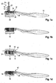
- the brush has a brush body 10 with a brush head, which in the following forms a base part 12.
- the base part 12 has numerous passage openings 14, which are filled with bristle tufts 16, which are fastened to the base part 12.
- FIG. 1 It can be seen that a transport device 18, which will be explained in more detail below, conveys individual bristle tufts 16, which are pushed by a device from the transport device 18 into the openings 14 from the rear side of the base part 12.
- the transport device 18 has a receiving opening 22 which is filled with a bristle tuft 16 and moved to the base part 12.
- the device 20 comprises a linearly movable plunger 24, which is inserted axially into the receiving opening 22 in order to push the bristle tufts 16 into the opening 14 of the base part 12 aligned with the receiving opening 22.
- the base part is moved along two axes and aligned with the opening to be filled 14 on the bristle tufts 16 to be introduced.
- a device-side guide part 26 preferably in contact with the front side of the base part 12, is arranged, whose through-holes 28 are aligned with the openings 14 to be populated.
- the bristle tufts 16 are so deeply into the base member 12 and the guide member 26 from the back of the base member 12, that is, from the back of the brush 10, pushed in that they protrude from the front of the guide member 16 again and abut against the stop member 30.
- the stop member 30 is removed. Instead, a pressure member 32 is moved from the front axially to the bristle tufts 16 upwards, so that it contacts all the bristle tufts 16. The top of the pressure member 32 is profiled to form a complementary brush surface (formed by the front ends of the bristle tufts 16).
- the bristle tufts 16 are pressed back up in part and are unevenly back against the base member 12 out.
- a counterpressure part 36 complementary to the pressure part can be provided on this rear side so that the bristle tufts 16 can be axially fixed between the pressure part 32 and counterpressure part 36 as far as possible without play.
- one of the pressure parts 32, 36 either elastically or elastically mounted.
- the front ends of the bristle tufts 16 have an exact alignment with the base part 12.
- bristle tufts 16 are attached at the back. This attachment is done for example by welding.
- FIG. 1e One way of welding is in Figure 1e shown in which a hot plate 38 is pressed against the bristle tufts 16.
- the back ends of the thermoplastic bristles fuse together, preferably to form a continuous layer 40 (see FIG FIG. 1f ).
- the pressure part 32 preferably remains on the bristle tufts 16.
- the pressure part 32 can now be removed (FIG. Figure 1g ), and then a rear lid part 40 is applied to the back of the base part 12, at least in the region of the ends of the bristle tufts 16 welded together.
- This cover part 40 may be a prefabricated part.
- the lid member 40 may also be made by injection molding to the base member 12 or to the brush body.
- the aforementioned use of sacrificial structures on the lid or on the brush body can also be used.
- the guide member 26 it is preferable (not limiting) for the guide member 26 to be supported on the base member 12 to provide support and sealing.
- FIG. 2 Further details of a possible embodiment of the station of the device according to the invention, in which the bristle tufts 16 are separated and transported to the base part 12.
- the device has its own station with a magazine 42, in which a bristle supply 44 is housed.
- the bristles are aligned in magazine 42 parallel and ungrouped housed. They are pressed by adapted pressure means in the direction of the transport device 18.
- the transport device 18 includes in the present, also not limiting embodiment to be pivoted about a pivot axis 46 to be pivoted removal device 48 with a plate-shaped bundle pickup, in the illustrated embodiment, a so-called circular arc having a receiving opening 50 for a bristle tufts 16.
- the receiving opening 50 is open on the side facing the brush holder 44 side. If the bundle taker to the right, based on FIG. 2 , is pivoted, the receiving opening 50 comes in contact with the bristle supply 44. Due to the bias of the bristle supply 44 in the direction of this receiving opening 50, so many bristles press into the receiving opening 50, that it is completely filled.
- the separation of the bristle tufts 16 thus takes place laterally to the longitudinal extension of the bristles, which in the present case would be perpendicular to the plane of the drawing.
- the receiving opening 50 When the receiving opening 50 is filled with bristles, it is pivoted clockwise and in the in FIG. 2 shown position moves.
- a guide plate 52 which conforms to the shape of the plate 48, ensures that no bristles can fall out of the receiving opening 50.
- a linear method can also be used.
- the bristle tufts 16 are pushed directly into the base part 12 directly, without the interposition of a carrier plate or the like. It should be noted that the individual bristle tufts are removed sequentially from the magazine 42 and transported with the tuft picker to their final position before impact. A transfer to subcarrier is avoided here.
- the base portion 12 has numerous openings 14 which must be successively filled with bristle tufts 16, the base portion 12 is moved in two directions X, Y. In order to be filled openings 14 are aligned with the receiving opening 50 and the next bristle tufts 16 to be injected.
- the corresponding station preferably has a so-called X-Y carriage, on which the base parts 12 can be fastened and moved in one plane.
- a so-called X-Y carriage is a simple embodiment of a freely programmable industrial robot, here a 2-axis industrial robot.
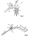
- FIG. 3 shows the magazine 42 with the tuft stock 44 in perspective view. To clarify the entire station several parts have been omitted.
- FIG. 3 further shows a bristle tufts 16, which is being pushed by the device 20 into an opening of the base part 12.
- a holder 54 positions and locks the guide member 26 to an alignment unit, such as an XY carriage, through which alignment of the base member 12 with the receiving aperture 50 occurs.
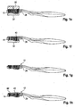
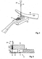
- FIG. 4 shows that the bristle tufts 16 project from the guide member 26 on the front side after being pushed into the openings 14 of the base part 12. However, the bristle tufts 16 are also in front of the base part 12, either directly after the impact or after the start of the pressure part 32.
- the loading with the bristle tufts 16 is in FIG. 5 shown in more detail. It can be seen that the bristle tufts 16 accommodated in the transport device 18 are spaced from the rear side of the base part 12 before being inserted into the openings 14. The transport device is spaced from the base part 12 in the region of the openings 14 via a gap 60 with the gap thickness d. This gap 60 is bridged by no guide member or the like.
- the transport device 18 is spaced.
- a corresponding gap D shows the smallest distance between the transport device 18 and the rear side of the base part 12.
- this gap D could also be zero, but the gap 60 is always present.
- the openings 14 are preferably provided on the back with a flared chamfer 62.
- the base part 12 has a depression 64 in the region of the openings 14 on the rear side. In this recess 64, the lid member 14 is introduced or molded.
- the transport device 18 is designed so that during the insertion of the bristles into the openings 14 in the transport device 18 exclusively axial pressure (that is, pressure in the bristle longitudinal direction) is exerted on the bristle tufts 16 to be introduced. That is, the wall around the receiving opening 50 is rigid, no radial clamping force is exerted on the bristles. The only clamping force is achieved by the bias in the bristle supply 44, which is forwarded so to speak in the receiving opening 50 when separating the bristles.
- the cutting of the bristle tufts 16 preferably takes place in a separate station of the device according to the invention, preferably by means of a heated tool.
- the cutting region is formed as an electrical resistance heater, i. this area is current-carrying.
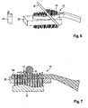
- FIG. 6 shows an embodiment of such a heated tool 70, which comprises a current-carrying, hot wire.
- This wire is moved substantially parallel to the back of the base part 12, as close as possible to the base part 12 along and separates the protruding bristle ends.
- bristles or neighboring bristle tufts 16 also partially merge with each other.
- FIG. 7 shows the effects of heat on not yet cut bristle tufts 16, which merge together. In addition, however, the already separated ends of remaining in the base part 12 bristle tufts 16 merge, which is advantageous for positioning and attachment.
- FIGS. 8a to 8c While in the Figures 5 and 6 a substantially circular cross-section wire as a tool 70 is shown in the FIGS. 8a to 8c to see an alternative embodiment with a so-called flat wire.
- heated wire is knife-like obliquely placed to the bristles to be separated.
- the inclination of the wire is chosen so that its pointing away from the base part inclined surface in Movement direction is inclined away from the base part. This supports a removal of the cut bristle ends away from the base part.
- the bristle tufts 16 are not laterally supported in the region of their interface.
- the tool 70 is not supported in the region of the base part 12, so that no wear occurs during cutting. The cutting takes place, so to speak, without support.
- the bristle tufts 16 are either laterally only through the base part 12 (see FIGS. 8a to 8c ) or held by the base part 12 and the guide member 26. In the axial direction, the bristle tufts 16 are positioned between the pressure part 32 and the counter-pressure part 36. This positioning should, but not in a limiting sense, be ensured even during cutting.
- the cutting is preferably carried out over the head, that is to say with the back side downwards (see, for example, FIG. 8 ) or with at least greatly skewed base part 12.
- the severed ends 72 simply fall down.
- the fastening of the bristle tufts 16 on the base part 12 takes place, as stated, either by welding and / or by gluing and / or by casting, for example during the production of the cover part 40.
- the cover part 40 can in particular rear projecting cleaning projections 80 have to form a tongue cleaner.
- the supplied cover part 40 can be subsequently pressed or glued, even using the aforementioned sacrificial structures.
- openings 14 must be closed by a bristle tufts 16. It may, as already mentioned, even one or the other opening 14 remain unfilled. When later gluing or potting or injection molding, the corresponding opening 14 is then closed.
- FIG. 6 it is also possible that some openings with an elastomeric profile member 82 are fitted, as exemplified in FIG. 6 is shown.
- the corresponding opening 14 in the base part 12 corresponds to this one-piece profile part, whose cross section is significantly larger than that of a bristle tufts 16.
- the profile part 82 can serve as a massage extension for gums or the like.
- the profile part 82 may either be prefabricated and then be mounted in the opening or sprayed immediately into / at the opening.
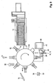
- FIG. 9 a device for producing the brush according to the method described above is shown.
- This device is designed as a tool, for example with a rotating table 100.
- each bristle tuft 16 is moved individually to the base part 12 (in this case the brush body 10) via the removal device 48 and the transport device 18, wherein previously the brush body 10 is placed on the guide member 26.
- a magazine with empty guide parts 26 may be present and is not shown here for clarity.
- each individual bristle tuft 16 is stuffed into the associated opening 14 by moving the laterally held guide part 26 in the X and Y directions.
- the finished assembled base 12 is then moved to the tool table 100 and attached to this.
- the rotating tool table 100 transports one or more of the base parts 12 to a station in which Figure 1 c Pressure and counterpressure 32, 36 align the tufts.
- the tufts are cut off at the back by means of the tool 70. This cutting can take place in a subsequent station or in the station in which the pressure and counterpressure parts 32, 36 are applied for the first time.
- the bristle tufts 16 are attached on the back, for example under the action of heat.
- lid part 40 is sprayed on.
- the finished brushes are removed and stacked, for example.
- the transport of the guide members 26 into the first station is not explicitly shown.
- the device mentioned above is slightly modified.
- the bristle tufts 16 is thereby bent in a U-shape to form two tuft ends.
- the anchor plate 80 presses or cuts into the wall 82 which defines the opening 14.
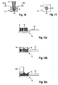
- FIGS. 12a to 12c are sequential process steps for trimming a brush body 10 already completed with bristle tufts 16 shown.
- the bristle tufts 16 can either be attached to the base part 12 via anchor plates 80 or else by other methods, for example the AFT method or the aforementioned method.
- a flat surface A formed by the front free ends of the bristles, is present after the placement and fastening of the bristle tufts ( FIG. 12a ).
- the hot tool 70 is moved obliquely inwards and outwards in order to cut off bristle ends in one or more work steps and to give the brush a profiled brush surface ( FIG. 12b ).
- a freely programmable positioning device can be used, by which the wire is moved along an arbitrarily pre-programmable path.
- a profile cutter 84 is used to form the already roughly worked with the hot tool 70 structure even finer and make a final cut on the bristles.
- the profile cutter 84 is an unheated cutting tool.
- the larger part of the bristles is cut off with the hot tool 70 and only a smaller part with the unheated, cutting cutting tool.
- a kind of device-side guide member may be present on the front side of the base member 12, from which the bristle tufts 16 protrude far enough to be edited and trimmed here without support.
- individual bristles, the elastomeric profile parts 82 or molded profile parts can be cut with the hot tool.
- the bristle ends could also be rounded or sharpened, if so desired.
- the wire used in the invention preferably has a thickness of about 0.2 mm and a width of 2 mm.
Landscapes
- Engineering & Computer Science (AREA)
- Manufacturing & Machinery (AREA)
- Brushes (AREA)
Claims (15)
- Procédé pour fabriquer des brosses au moyen d'un dispositif, les brosses comprenant une embase (12) formant au moins une portion d'un corps de brosse (10) et sur laquelle sont fixées des soies, caractérisé par les étapes suivantes :on coupe les soies au moyen d'un outil chauffé (70) avant de fixer les soies sur l'embase (12), l'outil chauffé (70) venant en contact avec les soies à couper, eton fixe les soies coupées, en particulier par touffes, sur l'embase (12).
- Procédé selon la revendication 1, caractérisé en ce que l'outil chauffé (70) comprend un fil chauffé qui coupe les brosses.
- Procédé selon la revendication 2, caractérisé en ce que le fil est un fil plat.
- Procédé selon la revendication 3, caractérisé en ce que le fil plat est déplacé en étant incliné en oblique par rapport aux soies.
- Procédé selon l'une des revendications précédentes, caractérisé en ce que les soies sont enfilées dans des ouvertures (14) de l'embase (12) et ensuite elles sont coupées au moyen de l'outil chauffé (70).
- Procédé selon l'une des revendications précédentes, caractérisé en ce qu'avant leur fixation sur l'embase (12), les soies font saillie du côté arrière des ouvertures (14) prévues dans l'embase et elles sont coupées sur le côté arrière.
- Procédé selon l'une des revendications précédentes, caractérisé en ce que la géométrie de l'outil et la température de l'outil (70) sont adaptées à la géométrie des soies de telle sorte que des soies, en particulier d'une touffe de soies (16), ou des touffes de soies (16) voisines sont soudées ensemble par la coupe.
- Procédé selon l'une des revendications précédentes, caractérisé en ce que lors de la coupe, l'embase (12) est orientée de telle sorte que les extrémités coupées (72) des soies tombent vers le bas en passant à côté des soies.
- Procédé selon l'une quelconque des revendications précédentes, caractérisé en ce que lors de la coupe, l'outil est déplacé transversalement aux soies à distance de l'embase (12) et sans corps d'appui.
- Procédé selon l'une quelconque des revendications précédentes, caractérisé en ce que des soies coupées par l'outil chauffé (70) continuent d'être coupées ensuite par un outil de coupe non chauffé.
- Procédé selon la revendication 10, caractérisé en ce qu'au moyen de l'outil chauffé (70), une surface de soie est pré-coupée et continue d'être coupée ensuite au moyen de l'outil de coupe non chauffé, en particulier au moyen d'une fraise profilée (84), en vue de créer une surface de brosse profilée.
- Procédé selon l'une quelconque des revendications précédentes, caractérisé en ce que les soies sont fixées sur l'embase (12) au moyen de plaquettes d'ancrage (80), par collage, par soudage ou par surmoulage.
- Dispositif pour fabriquer des brosses par un procédé selon l'une des revendications précédentes, caractérisé par
un dispositif de prélèvement (48) pour des touffes de soies (16) ou des soies,
un dispositif de transport (18) pour transporter des touffes de soies (16) ou des soies jusqu'à une embase (12) formant au moins une partie du corps de brosse (10),
un outil chauffé (70) destiné à couper des soies avant la fixation des soies sur l'embase (12), et
un poste de fixation dans lequel les soies coupées par l'outil chauffé (70) sont fixées, en particulier par touffes, sur l'embase (12). - Dispositif selon la revendication 13, caractérisé en ce qu'il comprend plusieurs postes de traitement qui sont parcourus successivement lors de la fabrication de la brosse.
- Dispositif selon la revendication 13 ou 14, caractérisé en ce que l'outil chauffé (70) est réalisé de telle sorte que les soies sont coupées sur le côté arrière de l'embase (12) avant d'être fixées sur l'embase (12).
Priority Applications (2)
| Application Number | Priority Date | Filing Date | Title |
|---|---|---|---|
| EP20100003938 EP2377425B1 (fr) | 2010-04-13 | 2010-04-13 | Dispositif et procédé de fabrication de brosses |
| CN201110092609.2A CN102258267B (zh) | 2010-04-13 | 2011-04-12 | 制造刷子的方法和装置 |
Applications Claiming Priority (1)
| Application Number | Priority Date | Filing Date | Title |
|---|---|---|---|
| EP20100003938 EP2377425B1 (fr) | 2010-04-13 | 2010-04-13 | Dispositif et procédé de fabrication de brosses |
Publications (2)
| Publication Number | Publication Date |
|---|---|
| EP2377425A1 EP2377425A1 (fr) | 2011-10-19 |
| EP2377425B1 true EP2377425B1 (fr) | 2013-10-23 |
Family
ID=42760344
Family Applications (1)
| Application Number | Title | Priority Date | Filing Date |
|---|---|---|---|
| EP20100003938 Active EP2377425B1 (fr) | 2010-04-13 | 2010-04-13 | Dispositif et procédé de fabrication de brosses |
Country Status (2)
| Country | Link |
|---|---|
| EP (1) | EP2377425B1 (fr) |
| CN (1) | CN102258267B (fr) |
Families Citing this family (3)
| Publication number | Priority date | Publication date | Assignee | Title |
|---|---|---|---|---|
| DE202012002332U1 (de) * | 2012-03-05 | 2012-03-22 | Gb Boucherie Nv | Vorrichtung zum Herstellen von Bürsten, insbesondere Zahnbürsten |
| AU2012396865B2 (en) | 2012-12-10 | 2015-11-19 | Colgate-Palmolive Company | Oral care implement |
| CA2909171A1 (fr) * | 2014-11-11 | 2016-05-11 | L G Harris & Co Limited | Ameliorations portant sur des pinceaux |
Family Cites Families (5)
| Publication number | Priority date | Publication date | Assignee | Title |
|---|---|---|---|---|
| GB863447A (en) * | 1958-12-08 | 1961-03-22 | Sarah Elizabeth Mortimer | Method of finishing nylon type tufts of brushes |
| DE3237885C2 (de) * | 1982-10-13 | 1986-01-16 | Krones Ag Hermann Kronseder Maschinenfabrik, 8402 Neutraubling | Verfahren und Vorrichtung zum Herstellen einer Förderschnecke für Gefäße |
| GB2286519B (en) * | 1994-02-18 | 1998-03-18 | Sanderson J & W Ltd | Two level tuft trimming of brush bristles |
| BE1013968A3 (nl) * | 2001-02-13 | 2003-01-14 | Boucherie Nv G B | Werkwijze voor het vervaardigen van borstels en inrichting voor het snijden van borstelvezels hierbij aangewend. |
| BE1017018A3 (nl) * | 2006-02-02 | 2007-12-04 | Boucherie Nv G B | Werkwijze voor het vervaardigen van borstels. |
-
2010
- 2010-04-13 EP EP20100003938 patent/EP2377425B1/fr active Active
-
2011
- 2011-04-12 CN CN201110092609.2A patent/CN102258267B/zh not_active Expired - Fee Related
Also Published As
| Publication number | Publication date |
|---|---|
| EP2377425A1 (fr) | 2011-10-19 |
| CN102258267A (zh) | 2011-11-30 |
| CN102258267B (zh) | 2015-05-27 |
Similar Documents
| Publication | Publication Date | Title |
|---|---|---|
| EP0346646B2 (fr) | Dispositif et procédé pour fabriquer des brosses | |
| DE69906425T2 (de) | Verfahren zum Herstellen von Bürsten sowie Bürstenherstellungsmaschine zur Durchführung dieses Verfahrens | |
| EP2130454A1 (fr) | Procédé de fabrication de brosses à dents à poils non ancrés | |
| DD281541A5 (de) | Verfahren und vorrichtung zur herstellung von aus borstentraeger und borsten aus kunststoff bestehenden borstenwaren | |
| CH641333A5 (de) | Verfahren und formwerkzeug zur herstellung eines mit stiftborsten versehenen borstentraegers fuer eine buerste, insbesondere haarbuerste. | |
| EP2377424B1 (fr) | Dispositif et procédé de fabrication de brosses | |
| EP2587959B1 (fr) | Procédé et dispositif de production de brosses | |
| DE102011013621B4 (de) | Verfahren und Vorrichtung zum Herstellen von Bürsten | |
| DE102012008536B4 (de) | Verfahren zum Herstellen von Bürsten sowie Bürste | |
| BE1022545B1 (de) | Bürstenherstellungsmaschine und Verfahren zum Einbringen von Borstenbündeln in Öffnungen eines Bündelträgers | |
| EP2377425B1 (fr) | Dispositif et procédé de fabrication de brosses | |
| DE102012021311A1 (de) | Vorrichtung und Verfahren zur Herstellung von Bürstenkörpern oder Teil-Bürstenkörpern | |
| DE102006057241A1 (de) | Maschine zum Herstellen von gedrehten Bürsten | |
| EP1060862B1 (fr) | Methode de moulage par injection et moule pour utiliser cette méthode de moulage | |
| DE19528834B4 (de) | Verfahren und Vorrichtung zum Profilieren und Nachbearbeiten von Borstenfeldern | |
| DE102005004661B4 (de) | Verfahren und Maschine zum Herstellen von Bürsten | |
| DE102004054839A1 (de) | Verfahren und Vorrichtung zum Herstellen von Bürsten | |
| EP2763567B1 (fr) | Procédé et dispositif pour la fabrication de brosses et brosse | |
| DE3742441C2 (de) | Hilfseinrichtung zum Beseitigen von Mängeln an Bürsten | |
| DE10017465B4 (de) | Verfahren und Vorrichtung zur Herstellung von Borstenwaren | |
| DE102006051356A1 (de) | Verfahren und Vorrichtung zum Herstellen von Bürsten | |
| DE1532795B2 (de) | Spritzgiessform zum herstellen von buersten | |
| DE3914821A1 (de) | Verfahren zum herstellen von buersten sowie buerstenherstellungsmaschine zur durchfuehrung des verfahrens | |
| DE29613940U1 (de) | Vorrichtung zur Herstellung von Borstenwaren | |
| DE29706613U1 (de) | Vorrichtung zur Herstellung von Borstenwaren, wie Bürsten und Besen o.dgl. |
Legal Events
| Date | Code | Title | Description |
|---|---|---|---|
| AK | Designated contracting states |
Kind code of ref document: A1 Designated state(s): AT BE BG CH CY CZ DE DK EE ES FI FR GB GR HR HU IE IS IT LI LT LU LV MC MK MT NL NO PL PT RO SE SI SK SM TR |
|
| AX | Request for extension of the european patent |
Extension state: AL BA ME RS |
|
| PUAI | Public reference made under article 153(3) epc to a published international application that has entered the european phase |
Free format text: ORIGINAL CODE: 0009012 |
|
| RAP1 | Party data changed (applicant data changed or rights of an application transferred) |
Owner name: GB BOUCHERIE NV |
|
| 17P | Request for examination filed |
Effective date: 20120416 |
|
| GRAP | Despatch of communication of intention to grant a patent |
Free format text: ORIGINAL CODE: EPIDOSNIGR1 |
|
| INTG | Intention to grant announced |
Effective date: 20130506 |
|
| GRAS | Grant fee paid |
Free format text: ORIGINAL CODE: EPIDOSNIGR3 |
|
| GRAA | (expected) grant |
Free format text: ORIGINAL CODE: 0009210 |
|
| AK | Designated contracting states |
Kind code of ref document: B1 Designated state(s): AT BE BG CH CY CZ DE DK EE ES FI FR GB GR HR HU IE IS IT LI LT LU LV MC MK MT NL NO PL PT RO SE SI SK SM TR |
|
| REG | Reference to a national code |
Ref country code: GB Ref legal event code: FG4D Free format text: NOT ENGLISH |
|
| REG | Reference to a national code |
Ref country code: CH Ref legal event code: EP Ref country code: CH Ref legal event code: NV Representative=s name: BUGNION S.A., CH |
|
| REG | Reference to a national code |
Ref country code: AT Ref legal event code: REF Ref document number: 637067 Country of ref document: AT Kind code of ref document: T Effective date: 20131115 |
|
| REG | Reference to a national code |
Ref country code: IE Ref legal event code: FG4D Free format text: LANGUAGE OF EP DOCUMENT: GERMAN |
|
| REG | Reference to a national code |
Ref country code: DE Ref legal event code: R096 Ref document number: 502010005129 Country of ref document: DE Effective date: 20131219 |
|
| REG | Reference to a national code |
Ref country code: NL Ref legal event code: VDEP Effective date: 20131023 |
|
| REG | Reference to a national code |
Ref country code: LT Ref legal event code: MG4D |
|
| PG25 | Lapsed in a contracting state [announced via postgrant information from national office to epo] |
Ref country code: SE Free format text: LAPSE BECAUSE OF FAILURE TO SUBMIT A TRANSLATION OF THE DESCRIPTION OR TO PAY THE FEE WITHIN THE PRESCRIBED TIME-LIMIT Effective date: 20131023 Ref country code: NO Free format text: LAPSE BECAUSE OF FAILURE TO SUBMIT A TRANSLATION OF THE DESCRIPTION OR TO PAY THE FEE WITHIN THE PRESCRIBED TIME-LIMIT Effective date: 20140123 Ref country code: LT Free format text: LAPSE BECAUSE OF FAILURE TO SUBMIT A TRANSLATION OF THE DESCRIPTION OR TO PAY THE FEE WITHIN THE PRESCRIBED TIME-LIMIT Effective date: 20131023 Ref country code: HR Free format text: LAPSE BECAUSE OF FAILURE TO SUBMIT A TRANSLATION OF THE DESCRIPTION OR TO PAY THE FEE WITHIN THE PRESCRIBED TIME-LIMIT Effective date: 20131023 Ref country code: NL Free format text: LAPSE BECAUSE OF FAILURE TO SUBMIT A TRANSLATION OF THE DESCRIPTION OR TO PAY THE FEE WITHIN THE PRESCRIBED TIME-LIMIT Effective date: 20131023 Ref country code: FI Free format text: LAPSE BECAUSE OF FAILURE TO SUBMIT A TRANSLATION OF THE DESCRIPTION OR TO PAY THE FEE WITHIN THE PRESCRIBED TIME-LIMIT Effective date: 20131023 Ref country code: IS Free format text: LAPSE BECAUSE OF FAILURE TO SUBMIT A TRANSLATION OF THE DESCRIPTION OR TO PAY THE FEE WITHIN THE PRESCRIBED TIME-LIMIT Effective date: 20140223 |
|
| PG25 | Lapsed in a contracting state [announced via postgrant information from national office to epo] |
Ref country code: LV Free format text: LAPSE BECAUSE OF FAILURE TO SUBMIT A TRANSLATION OF THE DESCRIPTION OR TO PAY THE FEE WITHIN THE PRESCRIBED TIME-LIMIT Effective date: 20131023 Ref country code: CY Free format text: LAPSE BECAUSE OF FAILURE TO SUBMIT A TRANSLATION OF THE DESCRIPTION OR TO PAY THE FEE WITHIN THE PRESCRIBED TIME-LIMIT Effective date: 20131023 Ref country code: ES Free format text: LAPSE BECAUSE OF FAILURE TO SUBMIT A TRANSLATION OF THE DESCRIPTION OR TO PAY THE FEE WITHIN THE PRESCRIBED TIME-LIMIT Effective date: 20131023 |
|
| PG25 | Lapsed in a contracting state [announced via postgrant information from national office to epo] |
Ref country code: PT Free format text: LAPSE BECAUSE OF FAILURE TO SUBMIT A TRANSLATION OF THE DESCRIPTION OR TO PAY THE FEE WITHIN THE PRESCRIBED TIME-LIMIT Effective date: 20140224 |
|
| REG | Reference to a national code |
Ref country code: DE Ref legal event code: R097 Ref document number: 502010005129 Country of ref document: DE |
|
| PG25 | Lapsed in a contracting state [announced via postgrant information from national office to epo] |
Ref country code: EE Free format text: LAPSE BECAUSE OF FAILURE TO SUBMIT A TRANSLATION OF THE DESCRIPTION OR TO PAY THE FEE WITHIN THE PRESCRIBED TIME-LIMIT Effective date: 20131023 |
|
| PG25 | Lapsed in a contracting state [announced via postgrant information from national office to epo] |
Ref country code: RO Free format text: LAPSE BECAUSE OF FAILURE TO SUBMIT A TRANSLATION OF THE DESCRIPTION OR TO PAY THE FEE WITHIN THE PRESCRIBED TIME-LIMIT Effective date: 20131023 Ref country code: PL Free format text: LAPSE BECAUSE OF FAILURE TO SUBMIT A TRANSLATION OF THE DESCRIPTION OR TO PAY THE FEE WITHIN THE PRESCRIBED TIME-LIMIT Effective date: 20131023 Ref country code: SK Free format text: LAPSE BECAUSE OF FAILURE TO SUBMIT A TRANSLATION OF THE DESCRIPTION OR TO PAY THE FEE WITHIN THE PRESCRIBED TIME-LIMIT Effective date: 20131023 Ref country code: CZ Free format text: LAPSE BECAUSE OF FAILURE TO SUBMIT A TRANSLATION OF THE DESCRIPTION OR TO PAY THE FEE WITHIN THE PRESCRIBED TIME-LIMIT Effective date: 20131023 |
|
| PLBE | No opposition filed within time limit |
Free format text: ORIGINAL CODE: 0009261 |
|
| STAA | Information on the status of an ep patent application or granted ep patent |
Free format text: STATUS: NO OPPOSITION FILED WITHIN TIME LIMIT |
|
| PG25 | Lapsed in a contracting state [announced via postgrant information from national office to epo] |
Ref country code: DK Free format text: LAPSE BECAUSE OF FAILURE TO SUBMIT A TRANSLATION OF THE DESCRIPTION OR TO PAY THE FEE WITHIN THE PRESCRIBED TIME-LIMIT Effective date: 20131023 |
|
| 26N | No opposition filed |
Effective date: 20140724 |
|
| REG | Reference to a national code |
Ref country code: DE Ref legal event code: R097 Ref document number: 502010005129 Country of ref document: DE Effective date: 20140724 |
|
| PG25 | Lapsed in a contracting state [announced via postgrant information from national office to epo] |
Ref country code: MC Free format text: LAPSE BECAUSE OF FAILURE TO SUBMIT A TRANSLATION OF THE DESCRIPTION OR TO PAY THE FEE WITHIN THE PRESCRIBED TIME-LIMIT Effective date: 20131023 Ref country code: LU Free format text: LAPSE BECAUSE OF FAILURE TO SUBMIT A TRANSLATION OF THE DESCRIPTION OR TO PAY THE FEE WITHIN THE PRESCRIBED TIME-LIMIT Effective date: 20140413 |
|
| GBPC | Gb: european patent ceased through non-payment of renewal fee |
Effective date: 20140413 |
|
| REG | Reference to a national code |
Ref country code: FR Ref legal event code: ST Effective date: 20141231 |
|
| REG | Reference to a national code |
Ref country code: IE Ref legal event code: MM4A |
|
| PG25 | Lapsed in a contracting state [announced via postgrant information from national office to epo] |
Ref country code: GB Free format text: LAPSE BECAUSE OF NON-PAYMENT OF DUE FEES Effective date: 20140413 |
|
| PG25 | Lapsed in a contracting state [announced via postgrant information from national office to epo] |
Ref country code: SI Free format text: LAPSE BECAUSE OF FAILURE TO SUBMIT A TRANSLATION OF THE DESCRIPTION OR TO PAY THE FEE WITHIN THE PRESCRIBED TIME-LIMIT Effective date: 20131023 Ref country code: FR Free format text: LAPSE BECAUSE OF NON-PAYMENT OF DUE FEES Effective date: 20140430 |
|
| PG25 | Lapsed in a contracting state [announced via postgrant information from national office to epo] |
Ref country code: IE Free format text: LAPSE BECAUSE OF NON-PAYMENT OF DUE FEES Effective date: 20140413 |
|
| PG25 | Lapsed in a contracting state [announced via postgrant information from national office to epo] |
Ref country code: MT Free format text: LAPSE BECAUSE OF FAILURE TO SUBMIT A TRANSLATION OF THE DESCRIPTION OR TO PAY THE FEE WITHIN THE PRESCRIBED TIME-LIMIT Effective date: 20131023 |
|
| PG25 | Lapsed in a contracting state [announced via postgrant information from national office to epo] |
Ref country code: SM Free format text: LAPSE BECAUSE OF FAILURE TO SUBMIT A TRANSLATION OF THE DESCRIPTION OR TO PAY THE FEE WITHIN THE PRESCRIBED TIME-LIMIT Effective date: 20131023 |
|
| REG | Reference to a national code |
Ref country code: AT Ref legal event code: MM01 Ref document number: 637067 Country of ref document: AT Kind code of ref document: T Effective date: 20150413 |
|
| PG25 | Lapsed in a contracting state [announced via postgrant information from national office to epo] |
Ref country code: GR Free format text: LAPSE BECAUSE OF FAILURE TO SUBMIT A TRANSLATION OF THE DESCRIPTION OR TO PAY THE FEE WITHIN THE PRESCRIBED TIME-LIMIT Effective date: 20140124 Ref country code: BG Free format text: LAPSE BECAUSE OF FAILURE TO SUBMIT A TRANSLATION OF THE DESCRIPTION OR TO PAY THE FEE WITHIN THE PRESCRIBED TIME-LIMIT Effective date: 20131023 |
|
| PG25 | Lapsed in a contracting state [announced via postgrant information from national office to epo] |
Ref country code: HU Free format text: LAPSE BECAUSE OF FAILURE TO SUBMIT A TRANSLATION OF THE DESCRIPTION OR TO PAY THE FEE WITHIN THE PRESCRIBED TIME-LIMIT; INVALID AB INITIO Effective date: 20100413 Ref country code: TR Free format text: LAPSE BECAUSE OF FAILURE TO SUBMIT A TRANSLATION OF THE DESCRIPTION OR TO PAY THE FEE WITHIN THE PRESCRIBED TIME-LIMIT Effective date: 20131023 |
|
| PGFP | Annual fee paid to national office [announced via postgrant information from national office to epo] |
Ref country code: CH Payment date: 20160420 Year of fee payment: 7 |
|
| PG25 | Lapsed in a contracting state [announced via postgrant information from national office to epo] |
Ref country code: AT Free format text: LAPSE BECAUSE OF NON-PAYMENT OF DUE FEES Effective date: 20150413 |
|
| PGFP | Annual fee paid to national office [announced via postgrant information from national office to epo] |
Ref country code: BE Payment date: 20160420 Year of fee payment: 7 |
|
| REG | Reference to a national code |
Ref country code: CH Ref legal event code: PL |
|
| PG25 | Lapsed in a contracting state [announced via postgrant information from national office to epo] |
Ref country code: CH Free format text: LAPSE BECAUSE OF NON-PAYMENT OF DUE FEES Effective date: 20170430 Ref country code: LI Free format text: LAPSE BECAUSE OF NON-PAYMENT OF DUE FEES Effective date: 20170430 |
|
| REG | Reference to a national code |
Ref country code: BE Ref legal event code: MM Effective date: 20170430 |
|
| PG25 | Lapsed in a contracting state [announced via postgrant information from national office to epo] |
Ref country code: BE Free format text: LAPSE BECAUSE OF NON-PAYMENT OF DUE FEES Effective date: 20170430 |
|
| PG25 | Lapsed in a contracting state [announced via postgrant information from national office to epo] |
Ref country code: MK Free format text: LAPSE BECAUSE OF FAILURE TO SUBMIT A TRANSLATION OF THE DESCRIPTION OR TO PAY THE FEE WITHIN THE PRESCRIBED TIME-LIMIT Effective date: 20131023 |
|
| PGFP | Annual fee paid to national office [announced via postgrant information from national office to epo] |
Ref country code: DE Payment date: 20240418 Year of fee payment: 15 |
|
| PGFP | Annual fee paid to national office [announced via postgrant information from national office to epo] |
Ref country code: IT Payment date: 20240424 Year of fee payment: 15 |