EP2375937B1 - Chaise - Google Patents
Chaise Download PDFInfo
- Publication number
- EP2375937B1 EP2375937B1 EP09832176.3A EP09832176A EP2375937B1 EP 2375937 B1 EP2375937 B1 EP 2375937B1 EP 09832176 A EP09832176 A EP 09832176A EP 2375937 B1 EP2375937 B1 EP 2375937B1
- Authority
- EP
- European Patent Office
- Prior art keywords
- shuttle
- chair
- recess
- recline
- seat
- Prior art date
- Legal status (The legal status is an assumption and is not a legal conclusion. Google has not performed a legal analysis and makes no representation as to the accuracy of the status listed.)
- Active
Links
- 230000007246 mechanism Effects 0.000 claims description 68
- 230000008261 resistance mechanism Effects 0.000 claims description 50
- 230000009471 action Effects 0.000 claims description 12
- 230000006835 compression Effects 0.000 claims description 10
- 238000007906 compression Methods 0.000 claims description 10
- 239000000463 material Substances 0.000 description 53
- 229920000139 polyethylene terephthalate Polymers 0.000 description 25
- 239000005020 polyethylene terephthalate Substances 0.000 description 25
- 239000011521 glass Substances 0.000 description 16
- 229920000728 polyester Polymers 0.000 description 14
- 239000004677 Nylon Substances 0.000 description 12
- 229920001778 nylon Polymers 0.000 description 12
- -1 polyethylene terephthalate Polymers 0.000 description 12
- 230000000712 assembly Effects 0.000 description 10
- 238000000429 assembly Methods 0.000 description 10
- 229910000831 Steel Inorganic materials 0.000 description 7
- 239000010959 steel Substances 0.000 description 7
- 229920001707 polybutylene terephthalate Polymers 0.000 description 6
- 230000007704 transition Effects 0.000 description 6
- 229920011687 Hytrel® 6356 Polymers 0.000 description 5
- 235000004443 Ricinus communis Nutrition 0.000 description 5
- 240000000528 Ricinus communis Species 0.000 description 4
- 125000002777 acetyl group Chemical group [H]C([H])([H])C(*)=O 0.000 description 4
- 238000010276 construction Methods 0.000 description 4
- 238000000034 method Methods 0.000 description 4
- 238000000465 moulding Methods 0.000 description 4
- 239000004814 polyurethane Substances 0.000 description 4
- HCHKCACWOHOZIP-UHFFFAOYSA-N Zinc Chemical compound [Zn] HCHKCACWOHOZIP-UHFFFAOYSA-N 0.000 description 3
- 230000000295 complement effect Effects 0.000 description 3
- 238000002347 injection Methods 0.000 description 3
- 239000007924 injection Substances 0.000 description 3
- 239000007769 metal material Substances 0.000 description 3
- 238000004064 recycling Methods 0.000 description 3
- 230000000007 visual effect Effects 0.000 description 3
- 229910052725 zinc Inorganic materials 0.000 description 3
- 239000011701 zinc Substances 0.000 description 3
- 229910000639 Spring steel Inorganic materials 0.000 description 2
- DHKHKXVYLBGOIT-UHFFFAOYSA-N acetaldehyde Diethyl Acetal Natural products CCOC(C)OCC DHKHKXVYLBGOIT-UHFFFAOYSA-N 0.000 description 2
- 229920001971 elastomer Polymers 0.000 description 2
- NJPPVKZQTLUDBO-UHFFFAOYSA-N novaluron Chemical compound C1=C(Cl)C(OC(F)(F)C(OC(F)(F)F)F)=CC=C1NC(=O)NC(=O)C1=C(F)C=CC=C1F NJPPVKZQTLUDBO-UHFFFAOYSA-N 0.000 description 2
- 229920003023 plastic Polymers 0.000 description 2
- 239000004033 plastic Substances 0.000 description 2
- 229920000642 polymer Polymers 0.000 description 2
- 229920002635 polyurethane Polymers 0.000 description 2
- 229920002261 Corn starch Polymers 0.000 description 1
- 229920011461 Hytrel® 4069 Polymers 0.000 description 1
- 239000000853 adhesive Substances 0.000 description 1
- 230000001070 adhesive effect Effects 0.000 description 1
- WYTGDNHDOZPMIW-RCBQFDQVSA-N alstonine Natural products C1=CC2=C3C=CC=CC3=NC2=C2N1C[C@H]1[C@H](C)OC=C(C(=O)OC)[C@H]1C2 WYTGDNHDOZPMIW-RCBQFDQVSA-N 0.000 description 1
- 229910052782 aluminium Inorganic materials 0.000 description 1
- XAGFODPZIPBFFR-UHFFFAOYSA-N aluminium Chemical compound [Al] XAGFODPZIPBFFR-UHFFFAOYSA-N 0.000 description 1
- 230000008859 change Effects 0.000 description 1
- 235000009508 confectionery Nutrition 0.000 description 1
- 239000008120 corn starch Substances 0.000 description 1
- 239000013536 elastomeric material Substances 0.000 description 1
- 230000007613 environmental effect Effects 0.000 description 1
- 239000006260 foam Substances 0.000 description 1
- 238000003197 gene knockdown Methods 0.000 description 1
- 210000004705 lumbosacral region Anatomy 0.000 description 1
- 239000012528 membrane Substances 0.000 description 1
- 229910052751 metal Inorganic materials 0.000 description 1
- 239000002184 metal Substances 0.000 description 1
- 238000012986 modification Methods 0.000 description 1
- 230000004048 modification Effects 0.000 description 1
- 238000012856 packing Methods 0.000 description 1
- 230000008569 process Effects 0.000 description 1
- 230000000452 restraining effect Effects 0.000 description 1
- 238000000926 separation method Methods 0.000 description 1
- 239000007787 solid Substances 0.000 description 1
- 238000005728 strengthening Methods 0.000 description 1
- 229920006346 thermoplastic polyester elastomer Polymers 0.000 description 1
Images


Classifications
-
- A—HUMAN NECESSITIES
- A47—FURNITURE; DOMESTIC ARTICLES OR APPLIANCES; COFFEE MILLS; SPICE MILLS; SUCTION CLEANERS IN GENERAL
- A47C—CHAIRS; SOFAS; BEDS
- A47C1/00—Chairs adapted for special purposes
- A47C1/02—Reclining or easy chairs
- A47C1/022—Reclining or easy chairs having independently-adjustable supporting parts
- A47C1/024—Reclining or easy chairs having independently-adjustable supporting parts the parts, being the back-rest, or the back-rest and seat unit, having adjustable and lockable inclination
- A47C1/027—Reclining or easy chairs having independently-adjustable supporting parts the parts, being the back-rest, or the back-rest and seat unit, having adjustable and lockable inclination by means of clamps or friction locking members
-
- A—HUMAN NECESSITIES
- A47—FURNITURE; DOMESTIC ARTICLES OR APPLIANCES; COFFEE MILLS; SPICE MILLS; SUCTION CLEANERS IN GENERAL
- A47C—CHAIRS; SOFAS; BEDS
- A47C1/00—Chairs adapted for special purposes
- A47C1/02—Reclining or easy chairs
- A47C1/022—Reclining or easy chairs having independently-adjustable supporting parts
- A47C1/03—Reclining or easy chairs having independently-adjustable supporting parts the parts being arm-rests
-
- A—HUMAN NECESSITIES
- A47—FURNITURE; DOMESTIC ARTICLES OR APPLIANCES; COFFEE MILLS; SPICE MILLS; SUCTION CLEANERS IN GENERAL
- A47C—CHAIRS; SOFAS; BEDS
- A47C1/00—Chairs adapted for special purposes
- A47C1/02—Reclining or easy chairs
- A47C1/031—Reclining or easy chairs having coupled concurrently adjustable supporting parts
- A47C1/032—Reclining or easy chairs having coupled concurrently adjustable supporting parts the parts being movably-coupled seat and back-rest
- A47C1/03255—Reclining or easy chairs having coupled concurrently adjustable supporting parts the parts being movably-coupled seat and back-rest with a central column, e.g. rocking office chairs
-
- A—HUMAN NECESSITIES
- A47—FURNITURE; DOMESTIC ARTICLES OR APPLIANCES; COFFEE MILLS; SPICE MILLS; SUCTION CLEANERS IN GENERAL
- A47C—CHAIRS; SOFAS; BEDS
- A47C1/00—Chairs adapted for special purposes
- A47C1/02—Reclining or easy chairs
- A47C1/031—Reclining or easy chairs having coupled concurrently adjustable supporting parts
- A47C1/032—Reclining or easy chairs having coupled concurrently adjustable supporting parts the parts being movably-coupled seat and back-rest
- A47C1/03261—Reclining or easy chairs having coupled concurrently adjustable supporting parts the parts being movably-coupled seat and back-rest characterised by elastic means
- A47C1/03277—Reclining or easy chairs having coupled concurrently adjustable supporting parts the parts being movably-coupled seat and back-rest characterised by elastic means with bar or leaf springs
-
- A—HUMAN NECESSITIES
- A47—FURNITURE; DOMESTIC ARTICLES OR APPLIANCES; COFFEE MILLS; SPICE MILLS; SUCTION CLEANERS IN GENERAL
- A47C—CHAIRS; SOFAS; BEDS
- A47C1/00—Chairs adapted for special purposes
- A47C1/02—Reclining or easy chairs
- A47C1/031—Reclining or easy chairs having coupled concurrently adjustable supporting parts
- A47C1/032—Reclining or easy chairs having coupled concurrently adjustable supporting parts the parts being movably-coupled seat and back-rest
- A47C1/03261—Reclining or easy chairs having coupled concurrently adjustable supporting parts the parts being movably-coupled seat and back-rest characterised by elastic means
- A47C1/03288—Reclining or easy chairs having coupled concurrently adjustable supporting parts the parts being movably-coupled seat and back-rest characterised by elastic means with resilient blocks
-
- A—HUMAN NECESSITIES
- A47—FURNITURE; DOMESTIC ARTICLES OR APPLIANCES; COFFEE MILLS; SPICE MILLS; SUCTION CLEANERS IN GENERAL
- A47C—CHAIRS; SOFAS; BEDS
- A47C3/00—Chairs characterised by structural features; Chairs or stools with rotatable or vertically-adjustable seats
- A47C3/20—Chairs or stools with vertically-adjustable seats
-
- A—HUMAN NECESSITIES
- A47—FURNITURE; DOMESTIC ARTICLES OR APPLIANCES; COFFEE MILLS; SPICE MILLS; SUCTION CLEANERS IN GENERAL
- A47C—CHAIRS; SOFAS; BEDS
- A47C31/00—Details or accessories for chairs, beds, or the like, not provided for in other groups of this subclass, e.g. upholstery fasteners, mattress protectors, stretching devices for mattress nets
- A47C31/02—Upholstery attaching means
-
- A—HUMAN NECESSITIES
- A47—FURNITURE; DOMESTIC ARTICLES OR APPLIANCES; COFFEE MILLS; SPICE MILLS; SUCTION CLEANERS IN GENERAL
- A47C—CHAIRS; SOFAS; BEDS
- A47C7/00—Parts, details, or accessories of chairs or stools
- A47C7/002—Chair or stool bases
- A47C7/004—Chair or stool bases for chairs or stools with central column, e.g. office chairs
-
- A—HUMAN NECESSITIES
- A47—FURNITURE; DOMESTIC ARTICLES OR APPLIANCES; COFFEE MILLS; SPICE MILLS; SUCTION CLEANERS IN GENERAL
- A47C—CHAIRS; SOFAS; BEDS
- A47C7/00—Parts, details, or accessories of chairs or stools
- A47C7/02—Seat parts
- A47C7/14—Seat parts of adjustable shape; elastically mounted ; adaptable to a user contour or ergonomic seating positions
-
- A—HUMAN NECESSITIES
- A47—FURNITURE; DOMESTIC ARTICLES OR APPLIANCES; COFFEE MILLS; SPICE MILLS; SUCTION CLEANERS IN GENERAL
- A47C—CHAIRS; SOFAS; BEDS
- A47C7/00—Parts, details, or accessories of chairs or stools
- A47C7/02—Seat parts
- A47C7/28—Seat parts with tensioned springs, e.g. of flat type
- A47C7/282—Seat parts with tensioned springs, e.g. of flat type with mesh-like supports, e.g. elastomeric membranes
-
- A—HUMAN NECESSITIES
- A47—FURNITURE; DOMESTIC ARTICLES OR APPLIANCES; COFFEE MILLS; SPICE MILLS; SUCTION CLEANERS IN GENERAL
- A47C—CHAIRS; SOFAS; BEDS
- A47C7/00—Parts, details, or accessories of chairs or stools
- A47C7/36—Support for the head or the back
- A47C7/40—Support for the head or the back for the back
- A47C7/44—Support for the head or the back for the back with elastically-mounted back-rest or backrest-seat unit in the base frame
- A47C7/445—Support for the head or the back for the back with elastically-mounted back-rest or backrest-seat unit in the base frame with bar or leaf springs
-
- A—HUMAN NECESSITIES
- A47—FURNITURE; DOMESTIC ARTICLES OR APPLIANCES; COFFEE MILLS; SPICE MILLS; SUCTION CLEANERS IN GENERAL
- A47C—CHAIRS; SOFAS; BEDS
- A47C7/00—Parts, details, or accessories of chairs or stools
- A47C7/02—Seat parts
- A47C7/16—Seats made of wooden, plastics, or metal sheet material; Panel seats
-
- Y—GENERAL TAGGING OF NEW TECHNOLOGICAL DEVELOPMENTS; GENERAL TAGGING OF CROSS-SECTIONAL TECHNOLOGIES SPANNING OVER SEVERAL SECTIONS OF THE IPC; TECHNICAL SUBJECTS COVERED BY FORMER USPC CROSS-REFERENCE ART COLLECTIONS [XRACs] AND DIGESTS
- Y10—TECHNICAL SUBJECTS COVERED BY FORMER USPC
- Y10T—TECHNICAL SUBJECTS COVERED BY FORMER US CLASSIFICATION
- Y10T29/00—Metal working
- Y10T29/49—Method of mechanical manufacture
- Y10T29/49826—Assembling or joining
Definitions
- aspects of the invention relate generally to chairs and associated components. More particularly, although not exclusively, some aspects of the invention relate to office chairs.
- reclining chairs have required a large number of separate interacting parts to provide reclining motion.
- the chairs often have a plurality of actuators to be gripped by a user to enable the chair to be adjusted.
- the chairs may require separate actuators for adjusting the height of the seat, the depth position of the seat, and recline of the back. Having a plurality of actuators can make the chairs difficult to adjust, and often require an occupant to visually inspect the actuators before they are able to make a desired adjustment. Otherwise, the occupant may adjust an incorrect actuator.
- Some supports of chairs have a frame and a cover attached to the frame.
- To attach the cover to the frame separate components or fasteners are generally required, such as screws or attachment strips for example.
- fasteners are generally required, such as screws or attachment strips for example.
- EP 0801913 , CA 1001966 , US 5090770 , US 5069496 , and US 4743065 disclose adjustable chairs.
- a chair comprising:
- the recline resistance mechanism applies no resistance against movement of the back portion toward the generally reclined position.
- the shuttle does not slide in the recess as the back portion of the chair is reclined.
- the recline resistance mechanism also resists movement of the back portion of the chair from the generally reclined position toward the generally upright position.
- the recess comprises a first engagement surface
- the recline resistance mechanism is configured such that as a portion of the shuttle engages the first engagement surface upon initial recline of the back portion toward the generally reclined position, the first engagement surface causes a first portion of said at least part of the shuttle to be compressed.
- the shuttle comprises a first engagement surface configured to engage with the first engagement surface of the recess.
- the first engagement surface of the shuttle is a leading surface of the shuttle, in the direction of sliding movement of the shuttle in the recess upon recline of the back portion.
- the recess comprises a second engagement surface
- the recline resistance mechanism is configured such that as a portion of the shuttle engages the second engagement surface upon further recline of the back portion toward the generally reclined position, the second engagement surface causes a second portion of said at least part of the shuttle to be compressed.
- the shuttle comprises a second engagement surface configured to engage with the second engagement surface of die recess.
- the second engagement surface of the shuttle is a trailing surface of the shuttle, in the direction of sliding movement of the shuttle in the recess upon recline of the back portion.
- first engagement surface of the shuttle could be a trailing surface of the shuttle and the second engagement surface of the shuttle could be a leading surface of the shuttle.
- the first portion of said at least part of the shuttle remains compressed when the second portion of said at least part of the shuttle is compressed.
- the total amount of compression of said at least part of the shuttle is greater, and thereby frictional force between the shuttle and the recess is greater, when the second portion of said at least part of the shuttle is also compressed than when only the first portion of said at least part of the shuttle is compressed.
- the frictional force that must be overcome to move the shuttle in the recess is between about 1177 Newtons (about 120 kg) and about 1471 Newtons (about 150 kg), when the first and second portions of said at least part of the shuttle is compressed.
- the force applied by said at least part of the shuttle, in a direction perpendicular to the direction of travel of the shuttle in the recess is between about 3922 Newtons (about 400 kg) and about 4413 Newtons (about 450 kg), when the first and second portions of said at least part of the shuttle is compressed.
- the recess can be in any suitable form.
- the sides of the recess could be closed or open, as could the upper end of the recess.
- the recess could be in the form of a channel having one open side, or could be substantially tubular having no open sides.
- the first and/or second engagement surfaces of the recess can be of any suitable shape and configuration.
- the first and second engagement surfaces of the recess comprise arcuate surfaces.
- the first and second engagement surfaces of the recess could comprise relatively sharp steps.
- the first and second engagement surfaces of the shuttle can be of any suitable shape and configuration.
- the first and second engagement surfaces of the shuttle comprise arcuate surfaces.
- the first and second engagement surfaces of the shuttle could comprise relatively sharp steps.
- the recess has a first portion having a relatively large dimension, a second portion having a relatively small dimension, and the first engagement surface of the recess comprises a transition surface between said first portion and said second portion, and the recline resistance mechanism is configured such that as part of the shuttle moves from the first portion to the second portion of the recess upon initial recline of the back portion toward the generally reclined position, frictional force between the shuttle and the recess increases due to compression of said at least part of the shuttle.
- the recess has a third portion of a relatively larger dimension than the first portion and second portion of the recess, with the first portion of the recess positioned between the second portion and third portion of the recess, and the recline resistance mechanism is configured such that as part of the shuttle moves from the third portion to the second portion of the recess upon further recline of the back portion toward the generally reclined position, frictional force between the shuttle and the recess increases further due to further compression of said at least part of the shuttle.
- substantially the entire shuttle could be resilient.
- at least the part of the shuttle having the engagement surface(s) is substantially rigid, so the engagement surface(s) don't deform upon engagement with the engagement surface(s) of the recess. Therefore, a side of the shuttle having the engagement surface(s) is preferably substantially rigid, with said at least part of the shuttle being an opposite side of the shuttle.
- said at least part of the shuttle comprises a resilient member that is housed at least partly within a body portion of the shuttle.
- part of the resilient member projects from the body portion of the shuttle.
- the resilient member preferably contacts a surface of the recess to provide frictional contact therebetween.
- the resilient member preferably contacts a wall of the recess to provide frictional contact therebetween.
- a suitable frictional surface may be attached to the resilient member, with at least part of the frictional surface projecting from the body portion of the shuttle and contacting the surface of the recess to provide frictional contact therebetween.
- the resilient member can be made from any suitable material, such as rubber or polyurethane for example.
- the resilient member is made from an elastomeric material, and preferably a thermoplastic polyester elastomer, such as HYTREL which is a polymer available from Du Pont.
- the resilient member could comprise a spring member, such as a compression spring or leaf spring for example, with a frictional pad attached to the spring.
- the spring could comprise a suitable polymeric material such as acetyl or nylon for example, or could comprise a metallic material.
- the remainder of the shuttle may be injection moulded from a suitable relatively rigid polymeric material, such as nylon for example.
- the part of the shuttle comprising the engagement surface(s) is substantially rigid, to prevent or minimise deformation of the engagement surfaces.
- the first and second chair components can be any suitable components, provided the first and second chair components move relative to each other upon reclining of the back portion.
- one of the components may be a supporting frame of the chair, and the other component may be any component that is adapted to move upon recline of the back portion toward the generally reclined position, such as a seat portion, seat support, or the back portion for example.
- said seat portion is slidable relative to the seat support to provide selective forward and rearward movement of the seat portion, and said first component comprises said seat support and said second component comprises said supporting frame.
- said first component comprises said seat support and said second component comprises said supporting frame.
- said first component may be one of the supporting frame and the back portion
- said second component may be the other of the supporting frame and the back portion
- the engaging member is pivoted to the second component.
- the engaging member and the shuttle preferably comprise complementary engagement features.
- the engagement features comprise respective hook features, but any other suitable configuration could be used.
- the chair preferably comprises an actuator that enables a user to engage or disengage the recline resistance mechanism.
- the actuator is preferably operatively connected to the engaging member by an overload protection device.
- the overload protection device can be any suitable form, but in a preferred embodiment the overload protection device comprises a biasing device such as a torsion spring. A different type of biasing device, such as a different type of spring could alternatively be used.
- the torsion spring is preferably connected directly to the actuator and the engaging member. Alternatively, one or more flexible elongate members, such as cables, could connect the torsion spring to the actuator and the engaging member.
- the actuator is movable between an engaging position corresponding to an engaged position of the engaging member and the shuttle, and a disengaging position corresponding to the disengaged position of the engaging member and the shuttle.
- the engaging member can only be disengaged from the shuttle when the back is in the generally upright configuration and is substantially unloaded.
- the overload protection device is preferably configured to bias the engaging member toward a disengaged position from the shuttle when the actuator is in the disengaging position, so that when the back portion returns to the generally upright configuration and is substantially unloaded, the engaging member will disengage from the shuttle.
- the engaging member can only be engaged with the shuttle when the back is in the generally upright configuration and is substantially unloaded.
- the overload protection device is preferably configured to bias the engaging member toward an engaged position with the shuttle when the actuator is in the engaging position, so that when the back portion returns to the generally upright configuration and is substantially unloaded, the engaging member will engage with the shuttle.
- the chair comprises a single actuator for actuating the recline resistance mechanism and a height adjust mechanism of the chair.
- the single actuator comprises a lever positioned generally beneath a seating surface of the chair.
- the lever is pivotable about a first axis to control the height adjust mechanism and is pivotable about a second axis to control the recline resistance mechanism.
- the first and second axes are substantially perpendicular.
- the first axis is a substantially horizontal axis
- the second axis is a substantially vertical axis.
- the movement about the second axis is indexed.
- the first chair component may be the seat portion or a seat support, and the chair may comprise a recline mechanism configured to move the seat portion or seat support upwardly upon a reclining action of the back portion.
- the recline mechanism is configured to lift the seat portion or seat support upon a reclining action of the back portion.
- the seat portion or seat support lifts and moves rearwardly upon a reclining action of the back portion.
- the seat portion or seat support may increase in rearward tilt angle as it lifts and moves rearwardly, or may maintain a substantially constant angle.
- the recline mechanism comprises a deformable member operatively connecting a portion of the seat support and the supporting frame, with the recline mechanism configured such that as the back portion of the chair is reclined, the deformable member deforms.
- the recline mechanism may comprise a puller that pulls the seat portion rearwardly upon a reclining action of the back portion.
- the recline resistance mechanism could be used in a chair having a different type of recline mechanism.
- the preferred form chairs may incorporate or use one or more of the features of the chairs described in our PCT application number PCT/NZ2007/000289 (published as WO 2008/041868 ), and the content of that specification is incorporated herein in its entirety by way of reference.
- PCT/NZ2007/000289 published as WO 2008/041868
- present specification does not repeat all of the features that are already described in the referenced PCT application. The reader should refer to that earlier specification for further explanation of features that are not described fully here.
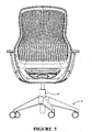
- Figures 1 to 7 illustrate a preferred form office task chair including a main assembly having a seat portion 13 and a back portion 15.
- the seat portion 13 and the back portion 15 are operatively supported above the ground by a supporting frame including a wheeled or castored base 11 having a central support column 17 which forms a height adjustment mechanism for selective height adjustment of the main assembly.
- the base 11 and height adjustment mechanism 17 form a height adjustment pedestal.
- An upper end of the height adjustment mechanism is connected to the main transom 21 of the chair.
- the castored base 11, height adjustment mechanism 17, and main transom 21 all form part of the supporting frame.
- the back portion 15 has a back frame 25.
- the overall frame width is relatively wide in a lower portion 27, relatively narrow in an intermediate region 29, and an upper portion 31 is wider than the intermediate region 29 but is generally narrower than the lower portion 27.
- the lower portion 27 is adapted to extend across and support at least a major part of a lower region of a seated adult occupant's back
- the upper portion is adapted to extend across and support at least a major part of an upper region of the occupant's back.
- the back frame 25 has a compliant cover 61 pulled taut and operatively connected to the upper and lower ends of the back frame and to the sides of the back frame to provide a supporting surface for the back of the seated occupant.
- the back portion has two spaced apart side members S1, S2.
- the lower portion 27 has a transversely extending lower member 33, and in that region the two spaced apart generally upright side members extend upwardly from the lower member 33 to form side member portions 35a, 35b.
- the portions 35a, 35b are each positioned at a respective end of the lower transverse member. From the transverse lower member 33, the portions 35a, 35b of side members S1, S2 initially extend upward, outward, and forward, and above that they subsequently extend upward, inward, and reward to form portions 36a, 36b.
- the transition between the initial part and the subsequent part forms a region 37a, 37b of the side members that has a convex curvature when viewed from the front of the back portion, and a convex curvature when viewed from a respective side of the back frame.
- the curvature of the side frame members changes to a concave curvature when viewed from die front of the back portion, and a concave curvature when viewed from a respective side of the back frame.
- the side frame members extend upwardly into the upper portion 31 of the back frame to form portions 41a, 41b. Those portions maintain a gently convex curvature when viewed from the front of the back portion and a gently convex curvature when viewed from a respective side of the back portion, for most of their lengths.
- the side members have a generally serpentine or sinuous shape in side view.
- the upper end of the frame is defined by a transverse cross member 43, which may extend rearwardly as shown in Figure 24 .
- the upper end of the back frame may be provided with a surface that enables a user's arm to be supported, such as the type described in our above-referenced PCT application for example.
- the lower portion of the back frame is relatively wide, to support a seated occupant when they are side- or angle-sitting.
- Portions 37a, 37b of the side frame members are configured to be positioned generally in the region of a seated adult occupant's lumbar region.
- the upper 43 and lower 33 members are generally concave when viewed from the front of the seat, with the concave curvature of the lower frame member being greater than that of the upper frame member.
- the lower portion of the back frame "cups" the lower back of the seated occupant.
- the upper portion 31 may also "cup" the back of adult seated occupant, although to a lesser extent than the lower portion 27 as an adult's upper back region is typically flatter and wider than their lower back region.
- the intermediate region 29 is of a resiliently flexible construction, to provide a flexing movement in a rearward direction of the upper portion 31 relative to the lower portion 27, as indicated by arrow R in Figure 3a .
- the back portion comprises at least one support member extending from the lower portion 27, to provide a means of supporting the back portion from another part of the chair, such as the main transom 21 of the supporting frame, the seat portion 13, or from both the seat portion and supporting frame.
- two horizontally spaced support members 45a, 45b extend downward, inward, and forward from the ends of lower transverse member 33.
- the support members have a concave curvature when viewed from the front of the back frame, and a concave curvature when viewed from a position between the members.
- the support members 45a, 45b are of a substantially rigid construction.
- the horizontally spaced support members 45a, 45b are adjoined at lower ends thereof by an integral transverse connector member 49.
- the transverse connector member incorporates an upper mounting region 49a for mounting a puller member 97 of the recline mechanism, and a lower mounting region 49b for mounting a lower deformable member 95 of the recline mechanism (see Figures 3d , 3e ).
- the puller and lower deformable member are preferably mounted to the mounting regions using screws that tap directly into the polymeric material of the frame. The recline mechanism will be described in more detail below.
- the side frame members S1, S2 preferably have the cross-sectional configuration shown in Figures 25 to 28 .
- side frame members are complex moulded articles that require internal cross-ribbing in the frame that adds to their moulding and visual complexity.
- cross-ribbing is not required for the frame.
- the side frame members are substantially L-shaped in cross-section as shown.
- the L shape comprises a main frame portion SA that forms a front face and a rearwardly extending side flange SB that is positioned at the outer edge of the main frame portion.
- the side flanges resist the majority of the loading applied to the back frame.
- the main frame portion SA and flange SB can have parallel walls, yet can still be moulded.
- the length of the flange SB is longer for a lower portion of the frame than for the upper portion of the frame.
- a similar design could be used for a seat frame that has a stretched cover in the manner described herein to form a seating surface for the occupant.
- the main frame portion SA would be a top portion of the frame that faces the seated occupant in use, and the flanges SB would extend downwardly therefrom.
- the front, rear, and side members may have the configuration shown in Figures 27, 28 .
- the back frame and support members are of a unitary construction, and may be moulded from a polymeric material for example, and preferably from a recyclable polymeric material.
- the back frame is moulded from a polymeric material having a polyester base.
- the recyclable polymeric material comprises one or more selected from the group comprising: polyethylene terephthalate, polybutylene terephthalate, polyester, recycled polyethylene terephthalate, recycled polybutylene terephthalate, recycled polyester, glass filled polyethylene terephthalate, and recycled glass filled polyethylene terephthalate.
- the cover is also moulded from a polymeric material having a polyester base, such as one of the materials outlined above for example.
- the cover is moulded from Hytrel.
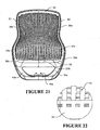
- the resiliently flexible compliant cover 61 shown in Figure 18 is pulled taut and connected to the back frame to provide a supporting surface for the back of the seated occupant.
- the cover extends over opening O between the upper, lower, and side members of the back frame.
- the cover is held in tension between the upper and lower and side members, and is suspended between the members.
- the cover is a resilient membrane or skin and is preferably generally of the type described in our above-referenced PCT application, and is stretched so that strain orientation of at least part of the cover occurs.
- the cover is preferably in form of a mesh as shown, but alternatively could be substantially solid.
- the cover is preferably moulded using the method described in our patent application numbers US 61/043283 (filed 8 April 2008 ) and 61/059036 (filed 5 June 2008 ) and PCT/NZ2009/000053 (published as WO 2009/126051 ), and the content of those specifications are incorporated herein in their entirety by way of reference.
- the cover could be formed using another technique, such as by extruding and die cutting die cover for example. Again, this type of cover is preferably stretched so that strain orientation of at least part of the cover occurs.
- the cover extends over the opening O between the side, upper, and lower members of the back frame, and is connected to the front faces of the side, upper, and lower members of the back frame so that outer parts of those members are exposed and not covered by the cover. That is, the outer edges of the back frame are not covered by the cover. Additionally, cover material usage is minimised by having the lower member 33 positioned reasonably high in the back frame, and by having the upper portion 31 of the back frame generally narrower than the lower portion 27 of the back frame.
- the cover is provided with attachment features that are integrally formed with the cover as part of the moulding process, and that are used to attach the cover to the frame.
- the frame has complementary attachment features to attach the cover to the frame.
- a preferred form seat depth adjustment mechanism is shown in Figures 29 to 36 and is indicated generally by reference numeral 401.
- the seat support 101 forms a seat slide that slidably supports the seat portion 13.
- the seat portion is preferably manufactured as a single injection moulded component, and preferably includes a seat panel 421, a plurality of resilient supports 423 that support the seat portion, and part of the seat depth engagement (which in the embodiment shown are channels 407 having left and right forward members 407a and left and right rear members 407b).
- the seat panel may be attached to the supports by suitable features such as clips for example.
- the seat panel 421 preferably also comprises zones of increased flexibility 425 for receiving an occupant's ischial protruberosities.
- the seat panel is preferably tiltable on the resilient supports 423 when a user's weight is offset, and the sides and front portion of the seat are preferably resiliently flexible to flex downward under the weight of an occupant's legs.
- the reader is referred to our above-referenced PCT application for further detail on the panel tilting and flexibility.
- the seat portion 13 is selectively moveable in a forward and rearward direction relative to the supporting frame.
- the seat portion has a locked configuration, shown in Figures 33a and 33d , and a released configuration, shown in Figure 33b and 33c .
- In the locked configuration forward and rearward movement relative to the supporting frame is minimised, and is preferably prevented.
- In the released configuration forward and rearward movement relative to the supporting frame is enabled.
- the chair has a seat support 101 and the seat portion 13 is slidable relative to the seat support to provide the selective forward and rearward movement of the seat portion.
- the seat portion 13 is adjustable from the locked configuration to the released configuration by raising a forward portion 403 of the seat portion relative to the seat support. In the embodiment shown, the forward portion 403 of the seat portion is lifted relative to the seat support 101 to release the seat portion from the locked configuration.
- the seat support has a pair of rails 405 with one rail 405 extending outwardly from each side.
- the seat portion comprises members in the form of channels 407 that slidably receive the rails.
- the channels may comprise continuous walls or, as shown, may comprise multiple members making up the channels. The configuration could be reversed, with the rails provided on the seat portion and members or channels formed on the seat support.
- the members 407a, 407b and rails 405 have a closer fit toward a rear portion 409 of the seat portion than toward a forward portion 403 of the seat portion.
- the closer fit may be provided by protrusions that extend into the channels or a narrowing of the channels towards the rear portion.
- the closer fit toward the rear portion allows sufficient movement between rails and channels at the forward portion of the seat portion and the seat support, to enable the seat portion to be adjusted to the released configuration by raising the forward portion of the seat portion 13 relative to the seat support 101.
- Figures 33a and 33b show the dimensions of a preferred embodiment configuration.
- D2 the spacing in the channel at a forward end of the mechanism
- D3 the spacing in the channel at a rear end of the mechanism
- D4 the length of the rails
- D5 the length of the lower end of the channel
- D6 the length of the upper end of the channel
- the chair comprises optional bearing members that provide a sliding interface between the members 407a, 407b and the rails 405.
- the bearing members 408a, 408b comprise liners made from a suitable material, such as nylon, Acetal, or polyester for example.
- the chair comprises two front bearing members 408a (which are preferably in the form of channels having side walls and upper and lower walls) and two rear bearing members 408b (which are preferably in the form of channels having side walls and upper and lower walls).
- the front bearing members 408a are mounted in the front members 407a and the rear bearing members 408b are mounted in the rear members 407b.
- the mounting can be of any suitable type, such as fasteners or adhesive for example.
- the front bearing members provide a sliding interface between the members and rails at a forward part of the seat portion and the rear bearing members provide a sliding interface between the members and rails at a rearward part of the seat portion.
- the bearing members may be mounted to the rails.
- the bearing members slidably engage the other of the members and the rails.
- each front bearing member 408a comprises an integrally formed leaf spring 408c.
- the leaf springs 408c act on the rails 405 to bias the forward portion of the seat portion downwardly relative to the seat support, to bias the seat portion into the locked configuration.
- One of the seat portion and die seat support comprises at least one projection 413, and the other of the seat portion and the seat support comprises a plurality of engagement features 415 for the projection(s).
- the seat portion comprises two engagement features 415 which, in the form shown, are recesses, and the seat support comprises a row of projections 413.
- the projections could instead be provided in the seat portion and the engagement features in the seat support.
- Two of the projections 413 engage in the recesses 415 when the seat portion is in the locked configuration, and do not engage with any of the recesses when the seat portion is in the released configuration.
- the chair may comprise two groups of engagement features that are each selectively engageable with at least one respective projection when the seat portion is in the locked configuration.
- the projections and engagement features are offset toward respective sides of the chair from a centre of the chair, so that at least one projection remains in engagement with an engagement feature if the seat portion is in a locked configuration and side loading is applied to the seat portion.
- the engagement features can comprise any suitable type, such as comprise a plurality of recesses or apertures 415 for example.
- the seat portion 13 is adjustable from the locked configuration to the released configuration by lifting the forward portion of the seat portion relative to the supporting frame, which releases the projections 413 from the apertures 415. The seat portion may then be moved forwardly or rearwardly to the new selected position. The seat portion is then lowered so that the projections 413 will engage the apertures corresponding to the new selected position.
- the seat portion may also have an indicator 417 to indicate the portion of the seat portion that should be raised to move the seat portion to the released configuration.
- the indicator may be a visual indicator, a tactile indicator, or a combination thereof.
- the indicator comprises a tactile indicator.
- the tactile indicator is provided on the underside of the front of the seat portion, and comprises a recess to receive a plurality of a user's fingers.
- a visual indicator may be provided in a front or upper surface of the seat portion, such as in a cushion cover for example.
- Figure 33a shows the seat portion in a most forward position.
- the forward portion of the seat lifted, as shown in Figure 33b .
- the projections 413 are clear of the recesses 415.
- the seat portion can then be moved to a rearward position.
- Figure 33c is a view similar to Figure 33b , but with the seat portion moved to a most rearward position.
- the leaf springs 408c have been flattened (against the bias of the spring) by lifting the forward portion of the seat portion.
- Figure 33d shows the forward portion of the seat portion lowered so the seat depth is locked. In that position, the projections 413 engage the recesses 415.
- the seat portion has a forward position, a rearward position, and at least one intermediate position.
- the front of the seat portion is resiliently flexible downwardly under the weight of an occupant's legs as the chair is reclined, in an upward direction the front of the seat portion is sufficiently rigid that a user can lift the front edge to enable depth adjustment of the seat portion.
- a cushion of any suitable type may be supported by the seat panel.
- a cushion cover may also be provided.
- the cushion and cushion cover are preferably recyclable polymeric material, such as the types described herein for example.
- the chair comprises a recline mechanism (described below) that is configured to move the seat support (and thereby the seat portion) upon recline of the back portion.
- seat depth adjustment could be incorporated into a different type of chair in which the seat support is a fixed part of the supporting frame.
- the seat support may, for example, be integrally moulded with a remainder of the supporting frame.
- the chair may be provided with arm assemblies 201.
- the arm assemblies are preferably attachable to another part of the chair, so that the chair can readily be configured with or without arm rests as desired.
- the features of the recline mechanism are most clearly seen in Figures 3a to 3e and 8a to 8f .
- the recline mechanism is generally similar to the type described in our above-referenced PCT application, and comprises two rear deformable members 91 extending between a relatively rearward portion of a seat support 101 and a relatively rearward portion of the transom 21, thereby operatively connecting a rearward portion of the seat portion and the supporting frame.
- the recline mechanism has some features that differ from that described and shown in the above-referenced PCT application.
- the mechanism further comprises two front deformable members 93 extending between a relatively forward portion of the seat support 101 and a relatively forward portion of the transom 21, thereby operatively connecting a more forward portion of the seat portion and the supporting frame.
- the mechanism further comprises a lower deformable member 95 connecting a lower part 49 of the back portion to the transom 21, and a puller member 97 above the lower deformable member, with the recline mechanism configured such that as the back portion of the chair is reclined, the lower deformable 95 member deforms and the puller member applies a rearward pulling action which causes the seat portion to move and the front 93 and rear 91 deformable members to deform.
- the lower deformable member 95 extends rearwardly from the main transom 21 of the chair to portion 49 of the back support, thereby operatively connecting a lower part of the back portion and the supporting frame.
- the lower deformable member can be connected to the back support and transom by any suitable means, but is preferably connected by screws that self-tap into the polymeric material of the back frame.
- the lower deformable member is in the form of a panel which extends substantially the width of the main transom.
- the puller member 97 extends from a rearward part of the seat support 101 to portion 49a of the back support, thereby operatively connecting the back portion to the seat portion.
- the puller member can be connected to the back support and seat support 101 by any suitable means, but is preferably connected by screws that self-tap into the polymeric materials of the back portion and seat portion.
- the front 93 and rear 91 deformable members are connected to the transom 21 and seat support 101 by screws.
- the front deformable members 93 are elongate members having a forward portion 93a connected to the seat support 101 and a rear portion 93b connected to the transom 21, and the two front deformable members extend predominantly in a forward-rearward direction of the chair but diverge from their rear portions 93b to their forward portions 93a such that their forward portions 93a are spaced further apart than their rear portions 93b.
- the front deformable members diverging as shown they twist as the seat portion is lifted during recline of the back portion. That provides greater stiffness in the front deformable members than if they extended only in a forward-rearward direction.
- the angle between a forward/rearward centreline of the chair and each front deformable member is between about 10 degrees and about 30 degrees, more preferably between about 20 degrees and about 30 degrees, more preferably about 26 degrees. That is, the included angle between the front deformable members may be between about 20 degrees and about 60 degrees, more preferably between about 40 and about 60 degrees, more preferably about 52 degrees.
- the rear flexing members 91 also diverge, but to a lesser extent than the front deformable members.
- the pulling action caused by the puller 97 causes the seat portion 13 to lift and move rearwardly.
- the puller member is preferably also deformable, although that is not essential. Because at least a major part - namely at least the rearward part - of the seat portion lifts and moves rearwardly as the back portion is reclined, the occupant's weight compensates the reclining action of the back portion. Accordingly, as the rearward force is removed from the back portion, the occupant's weight will cause the back portion to return to the upright position.
- the front and rear deformable members may increase in angle by between about 15 and about 16 degrees (measured between the mounting points at each end of the deformable members) as the back portion is reclined.
- recline mechanism may otherwise be of the type described in our above-referenced PCT application.
- the transom 21 is provided with two stops 103 to at least partly support the weight of the seated occupant on the seat portion 13 via the supporting frame when the back portion is not being reclined.
- the stops 103 are elongate members having a forward portion to support the seat portion and a rear portion operatively connected to the supporting frame (via the transom 21), and the stops extend predominantly in a forward-rearward direction of the chair but diverge from their rear portions to their forward portions.
- the stops are preferably integrally formed as part of the transom 21, and are suitably substantially rigid. Alternatively, the stops could be separate components connected to the transom.
- the stops 103 have a convex curvature relative to a position beneath the stops.
- the stops 103 are positioned adjacent the front deformable members, and in the form shown are positioned inwardly of the front deformable members 93. Alternatively, the stops could be provided outwardly of the front deformable members 93.
- the configuration of the stops directs loading from a seated occupant toward the height adjustment pedestal 17, which is received in cavity 21a of the transom.
- the transom 21 also includes two additional stops 104 that are formed by the upper surfaces of upright wall portions of the transom.
- the additional stops 104 support a more rearward part of the seat support 101, and thereby a more rearward part of the seat portion 13, when the back portion of the chair is not being reclined.
- the stops could be formed in any other suitable configuration, such as a single continuous surface for example.
- Upright wall portions 21 b extend across the back of the transom, and are integrally formed therewith.
- the upright wall portions 21b support a rear part 96 of the Hytrel over-moulding that incorporates the rear deformable members 91, the forward deformable members 93, and the bottom deformable member 95.
- forward deformable members 93 are connected to rear deformable members 91 by separator components 94, that comprise generally horizontal portion 94a and generally vertical portion 94b.
- the upright wall portions 21b also cooperate with part of the back portion, to define maximum recline position of the back portion.
- a forward portion of the back portion immediately below region 49a comprises an engagement face, that engages with the upright wall portions 21b to define the maximum recline position of the back portion.
- the front deformable members and the rear deformable member(s) are configured to deform into a generally sinuous shape as the back portion of the chair is reclined.
- this recline mechanism can be incorporated into a chair that does not have a depth adjustable seat portion.
- the mechanism can be tuned to obtain a desirable reclining action.
- the deformable members can be formed to provide variable resistance throughout the reclining action - such as greater resistance toward the reclined position for example.
- the members can be formed to provide a seat movement with or without a change in seat angle, and with or without an arcuate movement, depending on the action required.
- the recline mechanism preferably incorporates a recline resistance mechanism 301.
- a preferred form is shown in Figures 8a to 17b .
- the recline resistance mechanism is indicated generally by reference numeral 301.
- the back portion is reclinable relative to the supporting frame between a generally upright position GU and a generally reclined GR position.
- Figure 3c shows those positions.
- Figure 3c also shows the position of the seat when the back portion is in the upright position (and is labelled as SGU), and the seat when the back portion is in the reclined position (and is labelled SGR).
- the recline resistance mechanism 301 assists with maintaining the back portion in the generally upright position by providing a resistance force.
- the recline resistance mechanism is provided between the seat support 101 of the seat portion 13 and the transom 21 of the supporting frame.
- the recline resistance mechanism comprises a recess 311 in a first chair component - in this case in the seat support 101.
- the recess 311 has a first surface provided by a wall 313, and a second opposed surface provided by a wall 315.
- the first surface 313 is planar, and the opposed surface 315 is stepped.
- the recess opposed surface has a first portion having a relatively large dimension between a first wall 315a and the first surface 313, a second portion having a relatively small dimension between a second wall 315b and the first surface 313, and a transition surface 315c between the first wall 315a and the second wall 315b.
- the first wall 315a and second wall 315b are preferably substantially parallel to the opposed first surface 313.
- the transition surface 315c form a first engagement surface of the recess, that engages with a corresponding first engagement surface on the shuttle, as will be described below.
- the recess has a third portion of a relatively larger dimension than the first portion and second portion of the recess, the third portion being formed between a third wall 315d and the first surface 313.
- the first portion of the recess is positioned between the second portion and third portion of the recess.
- a transition surface 315e is positioned between the third wall 315d and the first wall 315a.
- the third wall 315d is preferably substantially parallel to the opposed first surface 313.
- the transition surface 315e forms a second engagement surface of the recess, that engages with a corresponding second engagement surface on the shuttle, as will be described below.
- the first engagement surface 315c and second engagement surface 315e of the recess can be of any suitable shape and configuration.
- the first and second engagement surfaces of the recess comprise arcuate surfaces.
- the first and second engagement surfaces of the recess could comprise relatively sharp steps.
- the recess can be in any suitable form.
- the sides of the recess could be closed or open, as could the upper end of the recess.
- the recess could be in the form of a channel having one open side, or could be substantially tubular having no open sides.
- a shuttle 351 is slidably engaged with the recess 311 in the seat support 101. At least part of the shuttle is resilient and configured such that as the shuttle slides through at least part of the recess, said at least part of the shuttle is compressed. Friction between the shuttle and the recess resist movement of the shuttle in the recess.
- the shuttle comprises a body 353 that may be injection moulded from a suitable relatively rigid polymeric material, such as Nylon for example.
- the shuttle body comprises a first engagement surface 355a and a second engagement surface 355b, which engage with the first engagement surface 315c and second engagement surface 315e respectively of the recess, when die shuttle slides in the recess.
- the first engagement surface 355a and second engagement surface 355b of the shuttle can be of any suitable shape and configuration.
- the first and second engagement surfaces of the shuttle comprise arcuate surfaces.
- the first and second engagement surfaces of the shuttle could comprise relatively sharp steps.
- the shuttle comprises a resilient member 357 in the form of a block that is housed at least partly within a body portion the shuttle.
- the resilient member is mounted in a recess 359 of the housing, and part of the resilient member 357 projects from the body portion of the shuttle to contact the first surface 313 of the recess.
- the resilient member 357 contacts the first surface 313 of the recess to provide frictional contact therebetween.
- a suitable frictional surface may be attached to the resilient member, with at least part of the frictional surface projecting from the body 353 of the shuttle and contacting the surface 313 of the recess to provide frictional contact therebetween.
- the resilient member can be made from any suitable material, such as rubber or polyurethane for example.
- the resilient member could comprise a spring member, such as a compression spring or leaf spring for example, with a frictional pad attached to the spring.
- the spring could comprise a suitable polymeric material such as acetyl or nylon for example, or could comprise a metallic material.
- the part of the shuttle comprising the engagement surface(s) 355a, 355b is substantially rigid, to prevent or minimise deformation of the engagement surfaces.
- substantially the entire shuttle could be resilient.
- An engaging member 371 is operatively connected to a second chair component - in this case to the transom 21.
- the engaging member 371 is actuable to selectively operatively engage the shuttle 351 or to selectively release the shuttle 351.
- the engaging member 371 is selectively operatively engaged with the shuttle as shown in Figure 11a for example, movement between the shuttle 351 and the transom 21 is restrained, so that upon movement of the back portion of the chair toward the generally reclined position GR, the shuttle 351 is caused to slide S in the recess 311, with friction between die resilient member 357 of the shuttle and the surface 313 of the recess applying a resistance against movement of the back portion toward the generally reclined GR position.
- the recline resistance mechanism applies no resistance against movement of the back portion toward the generally reclined GR position.
- the shuttle does not slide in the recess as the back portion of the chair is reclined, as shown in Figure 10b .
- the shuttle 351 is free to move with the seat support 101, and is not restrained by the engaging member.
- the engaging member 371 is pivoted to the transom 21 via pivot features 381a, 381b.
- the engaging member 371 and the shuttle 351 comprise complementary engagement features.
- the engagement features comprise respective hook features 373, 359, but any other suitable configuration could be used.
- the chair comprises an actuator 1201 that enables a user to engage or disengage the recline resistance mechanism.
- the actuator 1201 is operatively connected to the engaging member 371 by an overload protection device as will be described below.
- the actuator 1201 is movable between an engaging position corresponding to an engaged position of the engaging member and the shuttle (shown in Figure 11a ), and a disengaging position corresponding to the disengaged position of the engaging member and the shuttle (shown in Figure 10a ).
- the chair comprises a single actuator 1201 for actuating the recline resistance mechanism 301 and a height adjust mechanism 17 of the chair.
- the single actuator comprises a lever positioned generally beneath a seating surface of the chair.
- the lever is pivotable about a first axis to control the height adjust mechanism and is pivotable about a second axis to control die recline resistance mechanism. As shown in Figure 15b , movement of the lever 1201 in direction A will actuate the recline resistance mechanism.
- the lever 1201 has a paddle portion 1201a for receiving an occupant's fingers, and an actuating portion 1201b for actuating the height adjust mechanism.
- the paddle portion is lifted (direction B in Figure 15b )
- the lever moves about a generally horizontal axis and the actuating portion 1201b pushes down on a release member of the height adjust mechanism, to enable the height of the seat portion to be adjusted.
- the lever 1201 further has a second actuating portion 1201c for receiving the end of a member that operatively connects the lever to the engaging member 371.
- that member comprises a torsion spring 391.
- One end of the torsion spring 391 is received in the actuating portion 1201c of the lever, and the other end of the torsion spring is received in an aperture 375 in the engaging member 371.
- a body of the torsion spring 391 is mounted on an upstand 21u in the transom, as shown in Figure 9c .
- the lever is preferably provided as two separable components.
- the portion of the lever 1201b is positioned within the transom. That portion carries the two horizontally extending projections that can be seen in Figure 15a between portion 1201a and 1201b.
- the transom comprises a cavity for receipt of the projections.
- the portion 1201a can then be inserted through an aperture in the transom and connected to portion 1201b.
- the two horizontal projections on the lever define a horizontal axis for the lever.
- One of the horizontal projections will be a relatively tight fit in the cavity in the transom.
- the other horizontal projection will be a relatively loose fit, which provides the movement about a vertical axis.
- Detents will be provided in the transom to index movement of the projection that is a relatively loose fit.
- the recline resistance mechanism resists movement of the back portion of the chair from the generally upright position GU toward the generally reclined position GR, as well as from the reclined position GR toward the generally upright position GU, due to friction between the shuttle and recess.
- Figure 10a shows the engaging member 371 in a disengaged position.
- the shuttle 351 is not restrained by the engaging member 371 and therefore the shuttle 351 is not caused to slide in the recess 311 as the back portion of the chair is reclined to the generally reclined position represented by Figure 10b .
- Figure 11 shows the engagement member 371 is engaged with the shuttle 351. That figure represents the back portion being in the generally upright position GU. In that figure, the shuttle is positioned at an upper portion of the recess.
- Figure 12c shows the recline resistance mechanism when the back portion of the chair is in the generally reclined position GR. It can be seen that the shuttle 351 has been pulled downwardly within the recess, as a result of the engaging member 371 restraining movement of the shuttle 351 away from the transom 21.
- Figures 12a-12c show the staged movement of the shuttle 351 in the recess 311.
- Figure 12a shows the recline resistance mechanism upon initial recline of the back portion from the generally upright position GU toward the generally reclined position GR.
- the first engagement surfaces 315c, 355a cause a first portion 357a of the resilient member 357 to be compressed.
- the frictional force between the member 357 of the shuttle 351 and the first surface 313 of the recess 311 increases due to compression of that first part 357a of the member.
- the second engagement surfaces 335b, 315e cause a second portion 357b of the resilient member 357 to be compressed, as shown in Figure 12b .
- the frictional force between the shuttle and the recess increases further due to that further compression of the resilient member 351.
- the first portion 357a of the resilient member remains compressed when the second portion 357b is compressed. Therefore, the total amount of compression of the resilient member is greater, and thereby the frictional force between the shuttle 351 and the recess 311 is greater, when the second portion 357b of said at least part of the shuttle is also compressed than when only the first portion 357a of said at least part of the shuttle is compressed.
- me frictional force that must be overcome to move the shuttle 351 in the recess 311 is between about 1177 Newtons (about 120 kg) and about 1471 Newtons (about 150 kg), when the first 357a and second portions 357b of said at least part of the shuttle is compressed.
- the force applied by said at least part of the shuttle 353, in a direction perpendicular to die direction of travel of the shuttle in the recess is between about 3922 Newtons (about 400 kg) and about 4413 Newtons (about 450 kg), when the first 357a and second portions 357b of said at least part of the shuttle is compressed.
- the engagement of the first engagement surface of the shuttle with the first engagement surface of the recess, and of the second engagement surface of the shuttle with the second engagement surface of the recess, occurs during only the initial movement of the back portion from the generally upright position GU toward the generally reclined position GR.
- the generally reclined position GR of the chair is determined by stop(s) in the chair, rather than by movement of the shuttle in the recess. Therefore, the chair stop(s) will prevent further recline of the back portion before the second engagement surface 355b of the shuttle contacts the first engagement surface 315c of the recess.
- a projection 358 at the base of the shuttle engages on the transom 21, to cause the shuttle to slide upwardly in the recess as the back portion is moved from the generally reclined position GR back to the generally upright position GU. Again, there will be frictional restraint caused by the resilient member 357 sliding on the first surface 313 of the recess, as die recline resistance mechanism returns to the position shown in Figure 10a .
- the shuttle and recess may be configured as shown, such that the first engagement surfaces cause a leading portion of the resilient member to be compressed, in the direction of sliding movement of the shuttle in the recess upon recline of the back portion.
- a trailing portion of the resilient member could be compressed before the leading portion.
- the torsion spring 391 acts as an overload protection device.
- die overload protection device 391 is configured to bias the engaging member toward a disengaged position from the shuttle when the actuator is in the disengaging position. That biasing is represented by arrow B1 in Figure 14a . However, it is not until the back portion returns to the generally upright configuration GU and is substantially unloaded, that the biasing B1 will disengage the engaging member 371 from the shuttle 351.
- the engaging member 371 can only be engaged with the shuttle 351 when the back portion is in the generally upright configuration GU and is substantially unloaded.
- the overload protection device 391 is configured to bias the engaging member 371 toward an engaged position with the shuttle 351 when the actuator is in the engaging position. That biasing is represented by arrow B2 in Figure 13a .
- the biasing B2 will engage the engaging member 371 with the shuttle 351.
- the engaging member will engage with the shuttle (as shown in Figure 11a ).
- the overload protection device could be any other suitable form, such as a different type of biasing device, or a different type.
- one or more flexible elongate members such as cables, could connect the torsion spring to the actuator and the engaging member.
- the recess and shuttle are provided in the seat support 101, and the engaging member 371 is mounted to the transom.
- the seat support represents a first chair component
- the transom represents a second chair component.
- the first and second chair components can be any suitable components, provided the first and second chair components move relative to each other upon reclining of the back portion.
- one of the components may be a supporting frame of the chair, and the other component may be any component that is adapted to move upon recline of the back portion toward the generally reclined position, such as a seat portion, seat support, or the back portion for example.
- said first chair component may be one of the supporting frame and the back portion
- said second chair component may be the other of the supporting frame and the back portion
- the recline resistance mechanism could be used in a chair having a different type of recline mechanism to that described herein.
- the preferred embodiment chair is provided as a kit of parts that can be assembled into a chair by an end user.
- the kit comprises a number of separate components, as represented schematically in Figure 37a .
- the first component comprises the transom 21, recline mechanism, seat support 101, and back portion 15.
- the second component comprises the seat portion 13.
- the third component comprises the castored base 11.
- the fourth component comprises the height adjustment mechanism 17.
- the first, second, third, and fourth components can be assembled into a chair by an end user by mounting the fourth component to die third component, mounting the first component to the fourth component, and mounting the second component to the first component.
- the first, second, third, and fourth components will preferably each be pre-assembled or pre-formed components, with the four components being provided separately in the kit.
- the seat portion 13 as a separate component in the kit, the packing size can be significantly reduced over the size that would be required if the seat was preassembled with the seat support, recline mechanism, transom, and back.
- the kit may be provided in one or more package.
- the first component also comprises an actuator 1201 for use by a seated occupant to adjust the height of the height adjustment mechanism.
- the actuator 1201 is a lever.
- the actuator is preferably in the form of an elongate polymeric material lever 1201 that is pivotally mounted to the transom 21.
- the actuator self-adjusts to a desired position relative to the height adjustment mechanism 17 when the first component is mounted to the fourth component.
- the inner end of the actuator 1201 will move to sit against the top of the height adjustment mechanism release member 17a.
- the user will pull upwardly on the outer end of the lever, which will cause the inner end to push on the member 17a to actuate the height adjustment mechanism.
- the lever will be biased to the released position by the member 17a.
- the chair may be provided with arm assemblies 201.
- the kit will include a pair of arm assemblies.
- the arm assemblies will be pre-attached to the back portion and form part of the first component.
- the chair can be assembled from the kit parts in any suitable order.
- the second component is mountable to the first component
- the fourth component is mountable to the third component
- the first component is mountable to the fourth component, without the use of tools.
- substantially the entire first component, substantially the entire second component, and substantially the entire fourth component comprise recyclable polymeric materials as described below.
- the fourth component is mounted to the third component ( Figure 37b ), the first component is mounted to the fourth component ( Figure 37c ), and the second component is mounted to the first component ( Figure 37d ).
- the components can be assembled in any desired order.
- the second component may be mounted to the first component prior to mounting the first component to the fourth component
- the first component may be mounted to the fourth component prior to mounting the fourth component to the third component.
- the steps are carried out in the order outlined in the paragraph above.
- the chair may be disassembled so that such that substantially the entire chair can be recycled.
- die second component is separated from the first component
- the first component is separated from the fourth component
- the fourth component is separated from the third component.
- the step of disassembling the chair is preferably carried out without the use of tools or using standard hand tool(s).
- the screws that attach the front 93 and rear 95 deformable members of the recline mechanism to the seat support 101 will be removed, and the back portion 15 will be unscrewed from the lower deformable member 95 and the puller member 97.
- the screws that attach the puller member 97 to the seat support 101 will be removed.
- the metallic insert 1101 will be removed from the transom 21, and the castors and pins will be removed from the castored base. If necessary the back cover 61 will be removed from the back frame. Parts of the recline resistance mechanism will be removed.
- the arm rests 201 will be disconnected from the back portion by removing the fasteners. All of these steps can be carried out without tools or using standard hand tool(s) such as a screwdriver and hammer.
- the majority of the polymeric components (in the preferred embodiment, all that have a polyester base) can be recycled together, and the metallic components can be recycled together.
- At least a major part of the chair is manufactured from one or more materials that contain(s) recycled or renewably sourced content.
- "Renewably sourced content” is content that is sourced from a renewable resource, such as a renewable crop for example. Renewably sourced content differs from petrochemical-sourced content that is generally not renewable.
- One example of renewably sourced content is corn starch.
- At least a major part of the chair is manufactured from one or more materials that contain(s) content from a rapidly renewable resource.
- a rapidly renewable resource is a resource that can be harvested in less than 5 years from planting.
- the materials having recycled or renewably sourced content may also contain some virgin or non-recycled, non-renewably sourced content.
- the virgin or non-recycled, non-renewably sourced content may be petrochemical-sourced content.
- a major part of the chair uses compatible recyclable polymeric material(s) having a common base, so that significant parts of the chair can be recycled together without requiring excessive disassembly.
- the supporting frame, the recline mechanism, the seat portion, and the back portion are each substantially manufactured from one or more compatible recyclable polymeric materials.
- the supporting frame has a castored base.
- at least a major part of the castored base is manufactured from one or more recyclable polymeric materials.
- the central portion and integrally formed legs and flanges are manufactured from a recyclable polymeric material having a polyester base or from nylon for example.
- the castors or wheels of the base may necessarily have metal pins or shafts, and may need to be separated prior to recycling of the base. Alternatively, those components may be manufactured from one or more recyclable polymeric materials.
- the supporting frame further comprises a height adjustment mechanism.
- the height adjustment mechanism will generally not be recyclable with the remainder of the chair; although the metallic components of the height adjustment mechanism can be recycled with the metallic screws that are used to hold together other parts of the chair, as well as castor axles and any other metallic components.
- the supporting frame comprises a transom 21 having a cavity.
- the upper end of the height adjustment mechanism is received in a metallic insert in the cavity in the transom.
- the insert is removable from the transom by removing fasteners such as screws or by unscrewing the insert from the transom , to enable the transom and components connected to the transom to be recycled.
- the insert may be formed from a suitable metallic material, such as zinc, aluminum, or steel.
- the chair may be provided with height adjustable arm assemblies.
- the arm assemblies are formed from one or more recyclable polymeric materials.
- the arm assemblies are separable from the remainder of the chair, for example, by removing fasteners.
- the arm assemblies are made from one or more recyclable polymeric materials so that once the arm assemblies have been separated from the remainder of the chair, each arm assembly, other than the arm rest cushion, can be recycled as one unit without further disassembly.
- the arm rest cushion can be recycled with the remainder of the arm assembly.
- the recyclable polymeric material(s) used for at least a major part of the chair can be recycled together.
- the recyclable polymeric material(s) comprise material(s) having a polyester base.
- the recyclable polymeric material(s) comprise one or more selected from the group comprising: polyethylene terephthalate (PET), polybutylene terephthalate (PBT), polyester (PE), recycled polyethylene terephthalate, recycled polybutylene terephthalate, recycled polyester, glass filled polyethylene terephthalate, and recycled glass filled polyethylene terephthalate.
- At least about 60% of the chair, by weight comprises one or more polymeric materials that contain(s) recycled or renewably sourced content.
- at least about 70% of the chair, by weight comprises one or more polymeric materials that contain(s) recycled or renewably sourced content.
- at least about 80% of the chair, by weight comprises one or more polymeric materials that contain(s) recycled or renewably sourced content.
- the amount of recycled or renewably sourced content in the chair is at least about 40%, by weight.
- the amount of recycled or renewably sourced content in the chair is at least about 50%, by weight.
- the chair comprises about 46% recycled content by weight and about 6% of renewably sourced content by weight.
- the above describe two possible preferred embodiment material configurations.
- the second table describes a configuration that has a higher overall recycled/renewably sourced content than the first table.
- the materials used in the chair may be varied. However, it will be understood that in preferred embodiments of the chair, a major part of the chair is formed from one or more polymers that contain(s) recycled or renewably sourced content, and that are preferably compatible for recycling.
Claims (12)
- Chaise comprenant :un châssis de support (11, 17, 21) ;une portion d'assise (13) pour supporter un occupant ;et une portion de dossier (15) pour supporter le dos d'un occupant assis, la portion de dossier (15) pouvant être inclinée relativement au châssis de support (11, 17, 21) entre une position généralement redressée (GU) et une position généralement inclinée (GR) ;et un mécanisme de résistance à l'inclinaison (301) qui peut être mis en prise sélectivement pour résister à un mouvement de la portion de dossier (15) vers la position généralement inclinée (GR), le mécanisme de résistance à l'inclinaison (301) comprenant :un évidement (311) dans un premier composant de chaise ;une navette (351) qui est en prise de coulissement avec l'évidement (311) dans ledit premier composant de chaise, au moins une partie de la navette (351) étant résiliente et configurée de telle sorte que lorsque la navette (351) coulisse à travers au moins une partie de l'évidement (311), ladite au moins une partie de la navette (351) est compressée, avec une friction entre la navette (351) et l'évidement (311) résistant à un mouvement de la navette (351) dans l'évidement (311) ;un élément d'engagement (371) fonctionnellement relié à un deuxième composant de chaise, l'élément d'engagement (371) étant actionnable pour venir en prise fonctionnelle sélectivement avec la navette (351) ou pour libérer sélectivement la navette (351) ;dans laquelle, lorsque l'élément d'engagement (371) est fonctionnellement mis en prise avec la navette (351), un mouvement entre la navette (351) et le deuxième composant de chaise est résisté, de sorte que lors d'un mouvement de la portion de dossier (15) vers la position généralement inclinée (GR), la navette (351) est amenée à coulisser dans l'évidement (311), avec une friction entre la navette (351) et l'évidement (311) opposant une résistance à un mouvement de la portion de dossier (15) vers la position généralement inclinée (GR) ;et où le premier composant de chaise comprend un parmi le châssis de support (11, 17, 21), la portion d'assise (13) ou la portion de dossier (15), et où le deuxième composant de chaise comprend un autre parmi le châssis de support (11, 17, 21), la portion de siège (13) ou la portion de dossier (15), et où le premier composant de chaise et le deuxième composant de chaise sont configurés pour se déplacer l'un relativement à l'autre lors de l'inclinaison de la portion de dossier (15).
- Chaise selon la revendication 1, dans lequel, lorsque l'élément d'engagement (371) est libéré de la navette (351), le mécanisme de résistance à l'inclinaison (301) n'oppose pas de résistance au mouvement de la portion de dossier (15) vers la position généralement inclinée (GR).
- Chaise selon la revendication 1, dans laquelle, lorsque l'élément d'engagement (371) est sélectivement fonctionnellement mise en prise avec la navette (351), le mécanisme de résistance à l'inclinaison (301) résiste également à un mouvement de la portion de dossier (15) de la chaise de la position généralement inclinée (GR) vers la position généralement debout (GU).
- Chaise selon l'une quelconque des revendications 1 à 3, dans laquelle l'évidement (311) comprend une première surface d'engagement (315c), et le mécanisme de résistance à l'inclinaison (301) est configuré de telle sorte que lorsqu'une portion de la navette (351) vient en prise avec la première surface d'engagement (315c) lors d'une inclinaison initiale de la portion de dossier (15) vers la position généralement inclinée, la première surface d'engagement (315c) amène une première portion de ladite au moins une partie de la navette (351) à être compressée.
- Chaise selon la revendication 4, dans laquelle l'évidement comprend une deuxième surface d'engagement (315c), et le mécanisme de résistance à l'inclinaison (301) est configuré de telle sorte que lorsqu'une portion de la navette (351) vient en prise avec la deuxième surface d'engagement (315c) lors d'une poursuite de l'inclinaison de la portion de dossier (15) vers la position généralement inclinée, la deuxième surface d'engagement (315c) amène une deuxième portion de ladite au moins une partie de la navette (351) à être compressée.
- Chaise selon la revendication 5, dans laquelle la quantité de compression totale de ladite au moins une partie de la navette (351) est plus grande, et de ce fait la force de friction entre la navette (351) et l'évidement (311) est plus grande lorsque la deuxième portion de ladite au moins une partie de la navette (351) est également compressée que lorsque seulement la première portion de ladite au moins une partie de la navette (351) est compressée.
- Chaise selon l'une quelconque des revendications 1 à 6, dans laquelle ladite au moins une partie de la navette (351) comprend un élément résilient (357) qui est logé au moins partiellement dans une portion de corps (353) de la navette (351).
- Chaise selon la revendication 7, dans laquelle une partie de l'élément résilient (357) fait saillie de la portion de corps (353) de la navette et vient en contact avec une surface de l'évidement (311) pour réaliser un contact frictionnel entre celles-ci.
- Chaise selon l'une quelconque des revendications 1 à 8, dans laquelle la chaise comprend un actionneur (1201) qui permet à un utilisateur de mettre en ou hors prise le mécanisme de résistance à l'inclinaison (301), et l'actionneur est fonctionnellement relié à l'élément d'engagement (371) par un dispositif de protection contre une surcharge (391).
- Chaise selon l'une quelconque des revendications 1 à 9, dans laquelle un des composants est le châssis de support (11, 17, 21) de la chaise, et l'autre composant est la portion d'assise (13) ou la portion de dossier (15).
- Chaise selon la revendication 10, dans laquelle ladite portion d'assise (13) comprend un support de siège (101) pour réaliser un mouvement sélectif avant et arrière de la portion d'assise (13), et où ledit premier composant comprend ledit support de siège (101), et ledit deuxième composant comprend ledit châssis de support (11, 17, 21).
- Chaise selon l'une quelconque des revendications 1 à 11, où la chaise comprend un mécanisme d'inclinaison configuré pour déplacer la portion d'assise (13) ou le support de siège (101) vers le haut lors d'une action d'inclinaison de la portion de dossier (15), et le mécanisme d'inclinaison comprend un élément déformable (91, 93) reliant fonctionnellement une portion du support de siège (101) et le châssis de support (11, 17, 21) au mécanisme d'inclinaison configuré de telle sorte que lorsque la portion de dossier (15) de la chaise est inclinée, l'élément déformable se déforme.
Priority Applications (1)
| Application Number | Priority Date | Filing Date | Title |
|---|---|---|---|
| EP15167401.7A EP2939568B1 (fr) | 2008-12-12 | 2009-12-11 | Chaise |
Applications Claiming Priority (2)
| Application Number | Priority Date | Filing Date | Title |
|---|---|---|---|
| US12228308P | 2008-12-12 | 2008-12-12 | |
| PCT/NZ2009/000282 WO2010068122A1 (fr) | 2008-12-12 | 2009-12-11 | Chaise, support et composants |
Related Child Applications (2)
| Application Number | Title | Priority Date | Filing Date |
|---|---|---|---|
| EP15167401.7A Division-Into EP2939568B1 (fr) | 2008-12-12 | 2009-12-11 | Chaise |
| EP15167401.7A Division EP2939568B1 (fr) | 2008-12-12 | 2009-12-11 | Chaise |
Publications (3)
| Publication Number | Publication Date |
|---|---|
| EP2375937A1 EP2375937A1 (fr) | 2011-10-19 |
| EP2375937A4 EP2375937A4 (fr) | 2014-08-13 |
| EP2375937B1 true EP2375937B1 (fr) | 2015-07-29 |
Family
ID=42242926
Family Applications (2)
| Application Number | Title | Priority Date | Filing Date |
|---|---|---|---|
| EP15167401.7A Active EP2939568B1 (fr) | 2008-12-12 | 2009-12-11 | Chaise |
| EP09832176.3A Active EP2375937B1 (fr) | 2008-12-12 | 2009-12-11 | Chaise |
Family Applications Before (1)
| Application Number | Title | Priority Date | Filing Date |
|---|---|---|---|
| EP15167401.7A Active EP2939568B1 (fr) | 2008-12-12 | 2009-12-11 | Chaise |
Country Status (9)
| Country | Link |
|---|---|
| US (2) | US9033421B2 (fr) |
| EP (2) | EP2939568B1 (fr) |
| JP (3) | JP5552491B2 (fr) |
| AU (1) | AU2009325216B2 (fr) |
| CA (2) | CA2950118C (fr) |
| MX (1) | MX2011006225A (fr) |
| NZ (2) | NZ593679A (fr) |
| RU (1) | RU2518280C2 (fr) |
| WO (1) | WO2010068122A1 (fr) |
Families Citing this family (79)
| Publication number | Priority date | Publication date | Assignee | Title |
|---|---|---|---|---|
| US8251448B2 (en) | 2007-03-13 | 2012-08-28 | Hni Technologies Inc. | Dynamic chair back lumbar support system |
| EP2689693B1 (fr) | 2007-09-20 | 2016-09-14 | Herman Miller, Inc. | Structure de support |
| AU2009234514B2 (en) * | 2008-04-08 | 2014-05-01 | Formway Furniture Limited | Injection moulding method |
| CA2798444C (fr) | 2010-05-05 | 2023-02-28 | Eberhard Von Huene & Associates Inc. | Systeme de panneaux muraux mobile et demontable destine aux panneaux muraux vitres bout a bout |
| GB2481625B (en) * | 2010-07-01 | 2012-08-08 | James Lucas | Seat |
| KR101495243B1 (ko) * | 2011-05-02 | 2015-02-24 | 도요타 지도샤(주) | 차량용 시트 및 시트 백 보드 |
| US8991922B2 (en) | 2011-06-02 | 2015-03-31 | Formway Furniture Limited | Lumbar support for a chair |
| DE102011104972B4 (de) * | 2011-06-08 | 2015-03-05 | Haworth, Inc. | Sitzmöbel, insbesondere Bürostuhl |
| US8991921B2 (en) | 2012-07-20 | 2015-03-31 | Steelcase Inc. | Seating unit with seat position and depth adjustment assembly |
| US8998339B2 (en) | 2012-09-20 | 2015-04-07 | Steelcase Inc. | Chair assembly with upholstery covering |
| US11229294B2 (en) | 2012-09-20 | 2022-01-25 | Steelcase Inc. | Chair assembly with upholstery covering |
| US11304528B2 (en) | 2012-09-20 | 2022-04-19 | Steelcase Inc. | Chair assembly with upholstery covering |
| SG11201503010WA (en) | 2012-10-17 | 2015-05-28 | Formway Furniture Ltd | A chair and supports |
| WO2014144143A1 (fr) | 2013-03-15 | 2014-09-18 | Hni Technologies Inc. | Chaise ayant une flexion arrière activée |
| JP2014217545A (ja) * | 2013-05-08 | 2014-11-20 | タカノ株式会社 | 作業用椅子 |
| US10064493B2 (en) | 2014-04-17 | 2018-09-04 | Hni Technologies Inc. | Flex lumbar support |
| USD731833S1 (en) | 2014-04-17 | 2015-06-16 | Allsteel Inc. | Chair |
| WO2015172062A1 (fr) * | 2014-05-08 | 2015-11-12 | World Class Prototypes, Inc. | Ensemble substrat flexible et mobilier associé utilisant celui-ci |
| GB201412733D0 (en) * | 2014-07-17 | 2014-09-03 | Boss Design Ltd | Chair |
| CH710131B1 (de) * | 2014-09-19 | 2018-04-30 | Sitag Ag | Stuhl. |
| USD743180S1 (en) | 2014-10-15 | 2015-11-17 | Hni Technologies Inc. | Chair |
| US9801470B2 (en) | 2014-10-15 | 2017-10-31 | Hni Technologies Inc. | Molded chair with integrated support and method of making same |
| US20160128481A1 (en) * | 2014-11-11 | 2016-05-12 | Pro-Cord S.P.A. | Chair with seat and backrest movable in a synchronized way |
| US9883746B2 (en) * | 2014-11-11 | 2018-02-06 | Pro-Cord S.P.A. | Chair with seat and backrest movable in a synchronized way |
| WO2016115488A1 (fr) | 2015-01-16 | 2016-07-21 | Herman Miller, Inc. | Structure de siège à suspension par zones |
| US11596235B2 (en) * | 2015-02-11 | 2023-03-07 | Aaron DeJule | Apparatus with weight responsive changeable adjusting characteristics |
| US10292498B2 (en) | 2015-02-11 | 2019-05-21 | Aaron DeJule | Apparatus with weight responsive changeable adjusting characteristics |
| US10194750B2 (en) | 2015-04-13 | 2019-02-05 | Steelcase Inc. | Seating arrangement |
| US11259637B2 (en) * | 2015-04-13 | 2022-03-01 | Steelcase Inc. | Seating arrangement |
| MY189850A (en) | 2015-04-13 | 2022-03-14 | Steelcase Inc | Seating arrangement |
| US9770112B2 (en) * | 2015-06-26 | 2017-09-26 | Yao-Chuan Wu | Chair and furniture set with the chair |
| US20170291524A1 (en) * | 2016-04-11 | 2017-10-12 | Lear Corporation | Comfort system for seating backs with reduction in pur volume and environmentally friendly construction |
| US10463153B2 (en) | 2016-06-09 | 2019-11-05 | Steelcase Inc. | Seating arrangement |
| GB2551829B (en) * | 2016-06-30 | 2019-12-11 | Posturite Ltd | Chair with adjustable armrest |
| WO2018064029A1 (fr) | 2016-09-29 | 2018-04-05 | Steelcase Inc. | Structure d'assise souple |
| EP3387956B1 (fr) * | 2017-04-12 | 2019-05-22 | L&P Property Management Company | Chaise avec mécanisme d'actionnement de levier ayant un arbre à vis |
| US10315294B2 (en) * | 2017-05-09 | 2019-06-11 | Snap-On Incorporated | Inertial socket adaptor for torque application tools |
| US10561249B2 (en) | 2017-05-23 | 2020-02-18 | Yeti Coolers, Llc | Portable chair and cup holder assembly |
| US10743670B2 (en) * | 2017-05-23 | 2020-08-18 | Yeti Coolers, Llc | Portable chair and cup holder assembly |
| US10194749B1 (en) | 2017-05-23 | 2019-02-05 | Yeti Coolers, Llc | Portable chair and methods of forming a portable chair |
| US10966527B2 (en) * | 2017-06-09 | 2021-04-06 | Steelcase Inc. | Seating arrangement and method of construction |
| AU2018344896A1 (en) * | 2017-10-05 | 2020-05-21 | Godrej & Boyce Mfg. Co. Ltd., | Posture adaptive work chair |
| WO2019112956A1 (fr) * | 2017-12-05 | 2019-06-13 | Steelcase Inc. | Dossier souple |
| US10813463B2 (en) | 2017-12-05 | 2020-10-27 | Steelcase Inc. | Compliant backrest |
| US11291305B2 (en) | 2017-12-05 | 2022-04-05 | Steelcase Inc. | Compliant backrest |
| USD850810S1 (en) | 2018-01-10 | 2019-06-11 | Yeti Coolers, Llc | Portable chair |
| USD843152S1 (en) | 2018-01-10 | 2019-03-19 | Yeti Coolers, Llc | Portable chair |
| USD843151S1 (en) | 2018-01-10 | 2019-03-19 | Yeti Coolers, Llc | Portable chair |
| USD843150S1 (en) | 2018-01-10 | 2019-03-19 | Yeti Coolers, Llc | Portable chair |
| WO2019204714A1 (fr) * | 2018-04-19 | 2019-10-24 | Cramer Llc | Chaise dotée d'un dossier pliable et procédé associés |
| US11083301B2 (en) | 2018-06-01 | 2021-08-10 | Steelcase Inc. | Seating arrangement |
| CN113165560B (zh) * | 2018-08-03 | 2024-01-19 | 伊利诺斯工具制品有限公司 | 座椅和制造座椅的方法 |
| USD907382S1 (en) * | 2018-10-11 | 2021-01-12 | Knoll, Inc. | Chair |
| JP7251944B2 (ja) * | 2018-10-19 | 2023-04-04 | 株式会社オカムラ | 背凭れおよび椅子 |
| US11109683B2 (en) * | 2019-02-21 | 2021-09-07 | Steelcase Inc. | Body support assembly and method for the use and assembly thereof |
| EP3741258A1 (fr) * | 2019-05-20 | 2020-11-25 | BOCK 1 GmbH & Co. KG | Chaise pourvue de mécanisme d'inclinaison de l'assise |
| CN114502039A (zh) | 2019-09-18 | 2022-05-13 | 斯迪尔科斯公司 | 具有格架构造的身体支撑构件 |
| US11357329B2 (en) | 2019-12-13 | 2022-06-14 | Steelcase Inc. | Body support assembly and methods for the use and assembly thereof |
| CA3164328A1 (fr) * | 2019-12-13 | 2021-06-17 | Steelcase Inc. | Ensemble de support de corps et ses procedes d'utilisation et d'assemblage |
| USD924593S1 (en) * | 2019-12-20 | 2021-07-13 | Heping Chen | Chair |
| IT202000002332A1 (it) * | 2020-02-06 | 2021-08-06 | Donati Spa | Meccanismo di oscillazione per una sedia o una poltroncina |
| RU197561U1 (ru) * | 2020-02-13 | 2020-05-13 | Алексей Алексеевич Сибилев | Эргономичное кресло с индивидуальной настройкой опоры для спины пользователя |
| USD935824S1 (en) | 2020-02-19 | 2021-11-16 | Steelcase Inc. | Seat |
| USD961280S1 (en) | 2020-02-19 | 2022-08-23 | Steelcase Inc. | Chair |
| USD936985S1 (en) | 2020-02-19 | 2021-11-30 | Steelcase Inc. | Chair |
| USD961281S1 (en) | 2020-02-19 | 2022-08-23 | Steelcase Inc. | Chair |
| USD936984S1 (en) | 2020-02-19 | 2021-11-30 | Steelcase Inc. | Chair |
| USD961317S1 (en) | 2020-02-19 | 2022-08-23 | Steelcase Inc. | Backrest |
| USD937024S1 (en) | 2020-02-19 | 2021-11-30 | Steelcase Inc. | Backrest |
| USD937595S1 (en) | 2020-02-19 | 2021-12-07 | Steelcase Inc. | Chair |
| WO2021178206A1 (fr) | 2020-03-02 | 2021-09-10 | Steelcase Inc. | Ensemble de support de corps et ses procédés d'utilisation et d'assemblage |
| US11690455B2 (en) * | 2020-09-18 | 2023-07-04 | Dinkar Chellaram | Synchronous-tilt reclining chair |
| USD995179S1 (en) | 2021-01-20 | 2023-08-15 | Steelcase Inc. | Chair with lumbar support |
| USD988048S1 (en) | 2021-01-20 | 2023-06-06 | Steelcase Inc. | Lumbar support |
| WO2022173799A1 (fr) | 2021-02-10 | 2022-08-18 | Steelcase Inc. | Structures de support corporel |
| WO2022187667A1 (fr) * | 2021-03-04 | 2022-09-09 | Hni Technologies Inc. | Chaise présentant des caractéristiques de mouvement dynamique |
| USD995180S1 (en) | 2021-05-12 | 2023-08-15 | Steelcase Inc. | Chair with lumbar support |
| USD988049S1 (en) | 2021-05-12 | 2023-06-06 | Steelcase Inc. | Lumbar support |
| US11622631B1 (en) * | 2022-09-15 | 2023-04-11 | Jay A. Berkowitz | Apparatus and method for assembling a modular ergonomic chair without using fasteners |
Family Cites Families (112)
| Publication number | Priority date | Publication date | Assignee | Title |
|---|---|---|---|---|
| US3197789A (en) * | 1961-07-17 | 1965-08-03 | Joseph A Ashkouti | Folding furniture |
| US3235308A (en) | 1964-07-27 | 1966-02-15 | Flexible Air Seat Corp | Adjustable seat apparatus |
| US3709559A (en) | 1971-03-22 | 1973-01-09 | Rowland David L | Furniture for seating people |
| CA1001966A (en) * | 1972-04-03 | 1976-12-21 | Clyde R. Porter | Friction brake mechanism |
| CA975281A (en) * | 1972-11-15 | 1975-09-30 | Melvin A. Textoris | Chair base |
| US4340250A (en) | 1976-09-29 | 1982-07-20 | Minnesota Mining And Manufacturing Company | Platform rocking chair springs |
| US4119343A (en) | 1977-01-17 | 1978-10-10 | Kroehler Mfg. Co. | Platform rocker structure |
| US4183494A (en) | 1978-11-13 | 1980-01-15 | Trendler Metal Products, Inc. | Swiveled leaf-spring undercarriage for rocking chair |
| US4411468A (en) | 1981-03-05 | 1983-10-25 | Homecrest Industries Incorporated | Rocking chair |
| DE3119399C2 (de) | 1981-05-15 | 1986-04-10 | Keiper Recaro GmbH & Co, 7312 Kirchheim | Fahrzeugsitz |
| ATE12168T1 (de) | 1981-08-19 | 1985-04-15 | Giroflex Entwicklungs Ag | Stuhl. |
| EP0107627B1 (fr) | 1982-10-22 | 1986-01-02 | Castelli S.P.A. | Chaise dont le dossier comporte plusieurs segments articulés |
| US4582361A (en) | 1983-11-30 | 1986-04-15 | Kennel Stephen W | Lightweight seat frame for vehicles |
| CA1184108A (fr) | 1984-04-09 | 1985-03-19 | David W. Smith | Suspension de fauteuil basculant |
| US5050931A (en) | 1986-04-10 | 1991-09-24 | Steelcase Inc. | Controlled deflection front lip for seating |
| DE3617539C1 (de) | 1986-05-24 | 1987-07-23 | Grammer Sitzsysteme Gmbh | Sitz mit verstellbarer Sitzplatte und neigbarer Rueckenlehne |
| CH672237A5 (en) | 1986-10-14 | 1989-11-15 | Giroflex Entwicklungs Ag | Relaxing chair |
| DE3835003A1 (de) | 1988-10-14 | 1990-04-19 | Guenther Kuhn | Sessel oder stuhl, insbesondere buerosessel oder -stuhl |
| DE3913849A1 (de) * | 1989-04-27 | 1990-10-31 | Stabilus Gmbh | Sitzmoebel, insbesondere buerostuhl |
| US4911501A (en) | 1989-06-09 | 1990-03-27 | Harter Corporation | Suspension mechanism for connecting chair backs and seats to a pedestal |
| DE3930361C2 (de) | 1989-09-12 | 1993-11-04 | Simon Desanta | Stuhl, insbesondere buerostuhl |
| US5338091A (en) * | 1991-11-07 | 1994-08-16 | Miller Elmo E | Welt lock furniture construction |
| EP0856270A3 (fr) * | 1992-06-15 | 2000-08-30 | Herman Miller, Inc. | Colonne de support pour siège |
| US5409295A (en) | 1993-05-25 | 1995-04-25 | Omniflex Specialties | Omnidirectional tilting mechanism |
| US5439271A (en) * | 1993-11-08 | 1995-08-08 | Hoover Universal, Inc. | Vehicle seat with extruded frame members |
| JP2753964B2 (ja) * | 1994-07-20 | 1998-05-20 | 有限会社鳴戸木工 | 椅子の角度調節装置 |
| IT236832Y1 (it) * | 1995-04-21 | 2000-08-17 | Giuseppe Seroldi | Piano di sedile per poltrone divani sedie o simili con dispositividi fissaggio delle cinghie che sfruttano la tensione delle stesse |
| US5599064A (en) | 1995-07-27 | 1997-02-04 | Telescope Casual Furniture Co. | Swivel rocker |
| US5899530A (en) | 1995-08-23 | 1999-05-04 | Global Upholstery Company | Control mechanism for a chair |
| DE29601154U1 (de) * | 1996-01-24 | 1997-05-28 | Bayer Ag | Bürostuhl und Ellenbogenstützpolster für Bürostuhl |
| EP0801913A1 (fr) * | 1996-04-16 | 1997-10-22 | Cke Technologies Inc. | Dossier pour une chaise |
| DE19638075C1 (de) * | 1996-08-29 | 1998-02-26 | Jungjohann Thomas | Bremseinrichtung für ein bewegliches Bauteil eines Möbelelementes, insbesondere Polstermöbelelementes |
| US5755488A (en) | 1997-03-06 | 1998-05-26 | Steelcase Inc. | Chair with adjustable seat |
| JP3457496B2 (ja) * | 1997-04-11 | 2003-10-20 | 株式会社コトブキ | 椅子の背部構造 |
| US5934758A (en) | 1997-04-30 | 1999-08-10 | Haworth, Inc. | Membrane chair |
| TW381996B (en) * | 1997-10-21 | 2000-02-11 | Delta Tooling Co Ltd | Cushion and seat having a net-shaped skin |
| US6086153A (en) * | 1997-10-24 | 2000-07-11 | Steelcase Inc. | Chair with reclineable back and adjustable energy mechanism |
| US6375269B1 (en) * | 1997-11-25 | 2002-04-23 | Ts Tech Co., Ltd. | Seat having seating face made of sheet resilient material |
| US6250715B1 (en) * | 1998-01-21 | 2001-06-26 | Herman Miller, Inc. | Chair |
| JP4228355B2 (ja) * | 1998-03-19 | 2009-02-25 | テイ・エス テック株式会社 | 面状弾性体による座面部を有するシート |
| JP3200409B2 (ja) * | 1998-04-06 | 2001-08-20 | 愛知株式会社 | シート張設方法、椅子の座、および背凭 |
| US5984567A (en) * | 1998-07-09 | 1999-11-16 | Gollin & Co., Inc. | Molded split sleeve bushing for chair base |
| SE512805C2 (sv) | 1998-09-10 | 2000-05-15 | Bertil Jonsson | Stol |
| JP2000316664A (ja) * | 1999-05-06 | 2000-11-21 | T S Tec Kk | 面状弾性体による座面部を有するシート |
| US6168236B1 (en) * | 2000-01-10 | 2001-01-02 | Su-Jan Chen | Easy-to-assemble/recycle armrest |
| US6543843B1 (en) * | 2000-03-16 | 2003-04-08 | Johnson Controls Technology Company | Fastener strip |
| NZ504871A (en) | 2000-05-22 | 2002-04-26 | Miller Herman Inc | A chair with a preload mechanism to assist in the manufacture of reclining chairs so that the spring mechanism may be easily inserted |
| US6439665B1 (en) | 2000-06-09 | 2002-08-27 | Stylex | Ergonomic chair with mesh seat and back |
| US6540950B1 (en) * | 2000-09-20 | 2003-04-01 | Dahti, Inc. | Carrier and attachment method for load bearing fabric |
| AU783829B2 (en) | 2000-09-28 | 2005-12-08 | Formway Furniture Limited | A reclinable chair |
| AUPR054400A0 (en) * | 2000-09-29 | 2000-10-26 | Formway Furniture Limited | A castor |
| US6588843B1 (en) | 2000-10-06 | 2003-07-08 | Ghsp, Incorporated | Chair control |
| US6669301B1 (en) | 2000-11-28 | 2003-12-30 | Steelcase Development Corporation | Furniture article having panel and integral perimeter frame |
| JP4903328B2 (ja) * | 2000-12-28 | 2012-03-28 | タカノ株式会社 | 膜状部材取付構造 |
| US6842959B2 (en) * | 2001-01-25 | 2005-01-18 | Dahti, Inc. | Load bearing fabric attachment and associated method |
| DE10106792A1 (de) | 2001-02-12 | 2002-08-14 | Interstuhl Bueromoebel Gmbh | Sitzmöbel |
| DE10109624C1 (de) * | 2001-02-28 | 2002-09-12 | Interstuhl Bueromoebel Gmbh | Stuhl, insbesondere Bürostuhl |
| US6609755B2 (en) | 2001-06-15 | 2003-08-26 | Hon Technology Inc. | Ergonomic chair |
| US6983997B2 (en) * | 2001-06-29 | 2006-01-10 | Haworth, Inc. | Chair having a suspension seat assembly |
| UA49513C2 (en) * | 2001-12-18 | 2005-03-15 | Hennadii Yakovych Pryvalov | Supporting chair |
| NO317791B1 (no) * | 2002-01-04 | 2004-12-13 | Stokke As | Bevegelig ledd |
| US6550866B1 (en) * | 2002-01-24 | 2003-04-22 | Tung-Hua Su | Chair backrest with ventilating function |
| JP3967150B2 (ja) * | 2002-02-28 | 2007-08-29 | 株式会社イトーキ | 椅子 |
| JP4061147B2 (ja) * | 2002-07-23 | 2008-03-12 | 株式会社岡村製作所 | 椅子の座構造 |
| US6869142B2 (en) | 2002-09-12 | 2005-03-22 | Steelcase Development Corporation | Seating unit having motion control |
| US7334845B2 (en) * | 2002-09-12 | 2008-02-26 | Steelcase Development Corporation | Comfort surface for seating |
| US7226130B2 (en) * | 2002-09-12 | 2007-06-05 | Steelcase Development Corporation | Seating with comfort surface |
| US6742843B2 (en) | 2002-10-25 | 2004-06-01 | Knoll, Inc. | Cable control with overload protection device |
| FR2851524B1 (fr) * | 2003-02-21 | 2005-05-06 | Faurecia Sieges Automobile | Dossier de siege de vehicule automobile. |
| US7055911B2 (en) * | 2003-05-08 | 2006-06-06 | Haworth, Inc. | Mesh chair |
| IL157632A0 (en) * | 2003-08-28 | 2004-03-28 | Keter Plastic Ltd | Furniture item and a method for attaching webbing thereto |
| WO2005047057A2 (fr) * | 2003-11-11 | 2005-05-26 | Johnson Controls Technology Company | Mecanisme de reglage de dossier de siege |
| EP1541059A1 (fr) * | 2003-12-09 | 2005-06-15 | Chung-Li Shieh | Structure d'une chaise améliorée |
| US7066538B2 (en) | 2003-12-30 | 2006-06-27 | Hni Technologies, Inc. | Chair with tilt lock mechanism |
| US7147285B2 (en) | 2004-01-20 | 2006-12-12 | Tung Yu Oa Co., Ltd. | Reclining apparatus for chair |
| US7234777B2 (en) * | 2004-03-16 | 2007-06-26 | Kimball International, Inc. | Chair with adjustable armrests and backrest |
| US6979059B1 (en) | 2004-09-16 | 2005-12-27 | Hc Holdings, Llc | Rocking chair construction |
| JP4629395B2 (ja) * | 2004-09-22 | 2011-02-09 | 株式会社岡村製作所 | リクライニング椅子における背凭れの傾動装置 |
| US7108321B2 (en) * | 2004-10-04 | 2006-09-19 | Barton Brett Davis | Portable forward leaning stadium seat |
| JP4818601B2 (ja) * | 2004-10-13 | 2011-11-16 | 株式会社岡村製作所 | ハンガー付き椅子 |
| JP4875304B2 (ja) | 2005-02-09 | 2012-02-15 | 株式会社イトーキ | 椅子 |
| DE102005009419A1 (de) * | 2005-03-02 | 2006-09-07 | Recaro Aircraft Seating Gmbh & Co. Kg | Sitz |
| DE202005005947U1 (de) * | 2005-04-13 | 2005-09-29 | Tepe, Rainald | Hocker mit federweichen, beweglichen Füßen |
| US20070102987A1 (en) * | 2005-11-04 | 2007-05-10 | Su-Ming Chen | Meshed seat cushion for chair |
| US20070152488A1 (en) * | 2005-12-30 | 2007-07-05 | York Julie L | Arm rest using vertical lapped fiber |
| US20070170756A1 (en) * | 2006-01-25 | 2007-07-26 | Ming-Shiang Kang | Chair seat and back structure |
| US8465007B2 (en) * | 2006-03-22 | 2013-06-18 | Illinois Tool Works Inc. | Load bearing assembly with elastomeric edge |
| WO2007110729A2 (fr) | 2006-03-24 | 2007-10-04 | Herman Miller Inc. | Agencement de siege |
| WO2007110732A2 (fr) | 2006-03-24 | 2007-10-04 | Herman Miller Inc. | Meuble |
| US7543893B2 (en) | 2006-04-14 | 2009-06-09 | La-Z-Boy Incorporated | Rocking reclining chair |
| US7481495B2 (en) * | 2006-06-01 | 2009-01-27 | Agio International Company, Limited | System and method for mounting wicker |
| CN200953958Y (zh) * | 2006-09-30 | 2007-10-03 | 苏同华 | 座椅椅背 |
| NZ597812A (en) * | 2006-10-04 | 2013-04-26 | Formway Furniture Ltd | Back portion for a chair including upper section which folds rearwardly to reduce height of back portion and provide arm rest |
| JP4948975B2 (ja) * | 2006-11-10 | 2012-06-06 | 株式会社岡村製作所 | 椅子の背凭れ装置 |
| US7425039B2 (en) * | 2006-12-29 | 2008-09-16 | Peter Lin | Body-supporting device |
| DE202007000676U1 (de) * | 2007-01-14 | 2007-07-05 | Tepe-Walser, Silvia | Stuhlfuss |
| US7730594B2 (en) * | 2007-02-12 | 2010-06-08 | Yun-Chien Hsiao | Connector for stretch straps of a chair |
| TWM324454U (en) * | 2007-02-15 | 2008-01-01 | Hun Tai Plastic Co Ltd | Improved structure of chair-back |
| JP5154095B2 (ja) * | 2007-02-27 | 2013-02-27 | 株式会社岡村製作所 | 椅子における支基の構造 |
| ITMI20070718A1 (it) * | 2007-04-06 | 2008-10-07 | L & P Property Management Co | Dispositivo di regolazione per sedie regolabili e simili. |
| JP5013969B2 (ja) * | 2007-05-29 | 2012-08-29 | 株式会社イトーキ | ロッキング椅子 |
| US7604299B2 (en) | 2007-12-08 | 2009-10-20 | Tung-Hua Su | Backrest assembly |
| CN201189002Y (zh) * | 2008-03-24 | 2009-02-04 | 潘勇生 | 升降椅的支撑座 |
| AU2009234514B2 (en) | 2008-04-08 | 2014-05-01 | Formway Furniture Limited | Injection moulding method |
| US20100133893A1 (en) * | 2008-05-23 | 2010-06-03 | William Raftery | Chair having elastic bands for support surfaces and device for securing the bands to the chair |
| JP4695165B2 (ja) * | 2008-06-20 | 2011-06-08 | 株式会社岡村製作所 | 椅子における座の前後摺動装置 |
| JP5365167B2 (ja) * | 2008-11-28 | 2013-12-11 | トヨタ紡織株式会社 | 乗物シート用緩衝体 |
| JP5434211B2 (ja) * | 2009-04-09 | 2014-03-05 | トヨタ紡織株式会社 | 車両用シートの面状弾性体の組み付け構造 |
| US8109576B2 (en) * | 2010-01-25 | 2012-02-07 | Uei Yuang Enterprise Co., Ltd. | Seat assembly |
| US8622477B2 (en) * | 2011-02-10 | 2014-01-07 | L & P Property Management Company | Adjustable armrest for a seating unit |
| JP6122607B2 (ja) * | 2012-05-02 | 2017-04-26 | 株式会社岡村製作所 | 什器における高さ調節装置、およびそれを備える椅子の肘掛け装置 |
| SG11201503010WA (en) * | 2012-10-17 | 2015-05-28 | Formway Furniture Ltd | A chair and supports |
-
2009
- 2009-12-11 MX MX2011006225A patent/MX2011006225A/es active IP Right Grant
- 2009-12-11 AU AU2009325216A patent/AU2009325216B2/en active Active
- 2009-12-11 US US13/133,347 patent/US9033421B2/en active Active
- 2009-12-11 NZ NZ593679A patent/NZ593679A/xx unknown
- 2009-12-11 CA CA2950118A patent/CA2950118C/fr active Active
- 2009-12-11 EP EP15167401.7A patent/EP2939568B1/fr active Active
- 2009-12-11 NZ NZ61395709A patent/NZ613957A/en unknown
- 2009-12-11 CA CA2744491A patent/CA2744491C/fr active Active
- 2009-12-11 JP JP2011540624A patent/JP5552491B2/ja active Active
- 2009-12-11 RU RU2011121016/12A patent/RU2518280C2/ru not_active IP Right Cessation
- 2009-12-11 WO PCT/NZ2009/000282 patent/WO2010068122A1/fr active Application Filing
- 2009-12-11 EP EP09832176.3A patent/EP2375937B1/fr active Active
-
2014
- 2014-04-04 JP JP2014077469A patent/JP5823557B2/ja active Active
-
2015
- 2015-04-16 US US14/688,873 patent/US9622579B2/en active Active
- 2015-10-07 JP JP2015199112A patent/JP2016025956A/ja active Pending
Also Published As
| Publication number | Publication date |
|---|---|
| AU2009325216B2 (en) | 2015-12-10 |
| RU2011121016A (ru) | 2013-01-20 |
| EP2939568B1 (fr) | 2019-01-30 |
| RU2518280C2 (ru) | 2014-06-10 |
| US20120025574A1 (en) | 2012-02-02 |
| EP2939568A1 (fr) | 2015-11-04 |
| CA2744491C (fr) | 2017-01-10 |
| CA2744491A1 (fr) | 2010-06-17 |
| NZ613957A (en) | 2015-03-27 |
| EP2375937A4 (fr) | 2014-08-13 |
| MX2011006225A (es) | 2011-06-28 |
| CA2950118C (fr) | 2019-04-23 |
| EP2375937A1 (fr) | 2011-10-19 |
| AU2009325216A1 (en) | 2011-07-07 |
| NZ593679A (en) | 2013-08-30 |
| US9033421B2 (en) | 2015-05-19 |
| JP5552491B2 (ja) | 2014-07-16 |
| WO2010068122A9 (fr) | 2010-11-04 |
| CA2950118A1 (fr) | 2010-06-17 |
| US9622579B2 (en) | 2017-04-18 |
| JP2012511389A (ja) | 2012-05-24 |
| JP5823557B2 (ja) | 2015-11-25 |
| JP2016025956A (ja) | 2016-02-12 |
| US20150216308A1 (en) | 2015-08-06 |
| JP2014128734A (ja) | 2014-07-10 |
| WO2010068122A1 (fr) | 2010-06-17 |
Similar Documents
| Publication | Publication Date | Title |
|---|---|---|
| EP2375937B1 (fr) | Chaise | |
| US8029060B2 (en) | Chair | |
| CA2699914C (fr) | Structure de support de charge | |
| AU2004245064B2 (en) | Comfort surface for seating | |
| WO2009134451A1 (fr) | Mécanisme de tension pour une chaise sensible au poids | |
| US20240008651A1 (en) | Seating arrangement | |
| AU2015252092B2 (en) | A chair, a support, and components | |
| AU2013202886B2 (en) | A chair |
Legal Events
| Date | Code | Title | Description |
|---|---|---|---|
| PUAI | Public reference made under article 153(3) epc to a published international application that has entered the european phase |
Free format text: ORIGINAL CODE: 0009012 |
|
| 17P | Request for examination filed |
Effective date: 20110712 |
|
| AK | Designated contracting states |
Kind code of ref document: A1 Designated state(s): AT BE BG CH CY CZ DE DK EE ES FI FR GB GR HR HU IE IS IT LI LT LU LV MC MK MT NL NO PL PT RO SE SI SK SM TR |
|
| DAX | Request for extension of the european patent (deleted) | ||
| A4 | Supplementary search report drawn up and despatched |
Effective date: 20140714 |
|
| RIC1 | Information provided on ipc code assigned before grant |
Ipc: A47C 5/00 20060101ALI20140708BHEP Ipc: A47C 1/023 20060101AFI20140708BHEP Ipc: A47C 1/032 20060101ALI20140708BHEP Ipc: A47C 7/00 20060101ALI20140708BHEP Ipc: A47C 1/022 20060101ALI20140708BHEP Ipc: A47C 1/024 20060101ALI20140708BHEP Ipc: A47C 1/02 20060101ALI20140708BHEP Ipc: A47C 7/54 20060101ALI20140708BHEP Ipc: A47C 3/20 20060101ALI20140708BHEP Ipc: A47C 7/14 20060101ALI20140708BHEP |
|
| GRAP | Despatch of communication of intention to grant a patent |
Free format text: ORIGINAL CODE: EPIDOSNIGR1 |
|
| RIC1 | Information provided on ipc code assigned before grant |
Ipc: A47C 7/14 20060101ALI20150309BHEP Ipc: A47C 3/20 20060101ALI20150309BHEP Ipc: A47C 7/00 20060101ALI20150309BHEP Ipc: A47C 1/032 20060101ALI20150309BHEP Ipc: A47C 1/02 20060101ALI20150309BHEP Ipc: A47C 1/022 20060101ALI20150309BHEP Ipc: A47C 1/024 20060101ALI20150309BHEP Ipc: A47C 5/00 20060101ALI20150309BHEP Ipc: A47C 7/54 20060101ALI20150309BHEP Ipc: A47C 1/023 20060101AFI20150309BHEP |
|
| INTG | Intention to grant announced |
Effective date: 20150331 |
|
| RAP1 | Party data changed (applicant data changed or rights of an application transferred) |
Owner name: FORMWAY FURNITURE LIMITED |
|
| GRAP | Despatch of communication of intention to grant a patent |
Free format text: ORIGINAL CODE: EPIDOSNIGR1 |
|
| GRAS | Grant fee paid |
Free format text: ORIGINAL CODE: EPIDOSNIGR3 |
|
| GRAA | (expected) grant |
Free format text: ORIGINAL CODE: 0009210 |
|
| INTG | Intention to grant announced |
Effective date: 20150612 |
|
| RAP1 | Party data changed (applicant data changed or rights of an application transferred) |
Owner name: FORMWAY FURNITURE LIMITED |
|
| AK | Designated contracting states |
Kind code of ref document: B1 Designated state(s): AT BE BG CH CY CZ DE DK EE ES FI FR GB GR HR HU IE IS IT LI LT LU LV MC MK MT NL NO PL PT RO SE SI SK SM TR |
|
| REG | Reference to a national code |
Ref country code: GB Ref legal event code: FG4D |
|
| REG | Reference to a national code |
Ref country code: CH Ref legal event code: EP |
|
| REG | Reference to a national code |
Ref country code: AT Ref legal event code: REF Ref document number: 738591 Country of ref document: AT Kind code of ref document: T Effective date: 20150815 |
|
| REG | Reference to a national code |
Ref country code: IE Ref legal event code: FG4D |
|
| REG | Reference to a national code |
Ref country code: DE Ref legal event code: R096 Ref document number: 602009032590 Country of ref document: DE |
|
| REG | Reference to a national code |
Ref country code: FR Ref legal event code: PLFP Year of fee payment: 7 |
|
| REG | Reference to a national code |
Ref country code: AT Ref legal event code: MK05 Ref document number: 738591 Country of ref document: AT Kind code of ref document: T Effective date: 20150729 |
|
| REG | Reference to a national code |
Ref country code: LT Ref legal event code: MG4D |
|
| REG | Reference to a national code |
Ref country code: NL Ref legal event code: MP Effective date: 20150729 |
|
| PG25 | Lapsed in a contracting state [announced via postgrant information from national office to epo] |
Ref country code: LV Free format text: LAPSE BECAUSE OF FAILURE TO SUBMIT A TRANSLATION OF THE DESCRIPTION OR TO PAY THE FEE WITHIN THE PRESCRIBED TIME-LIMIT Effective date: 20150729 Ref country code: FI Free format text: LAPSE BECAUSE OF FAILURE TO SUBMIT A TRANSLATION OF THE DESCRIPTION OR TO PAY THE FEE WITHIN THE PRESCRIBED TIME-LIMIT Effective date: 20150729 Ref country code: LT Free format text: LAPSE BECAUSE OF FAILURE TO SUBMIT A TRANSLATION OF THE DESCRIPTION OR TO PAY THE FEE WITHIN THE PRESCRIBED TIME-LIMIT Effective date: 20150729 Ref country code: NO Free format text: LAPSE BECAUSE OF FAILURE TO SUBMIT A TRANSLATION OF THE DESCRIPTION OR TO PAY THE FEE WITHIN THE PRESCRIBED TIME-LIMIT Effective date: 20151029 Ref country code: GR Free format text: LAPSE BECAUSE OF FAILURE TO SUBMIT A TRANSLATION OF THE DESCRIPTION OR TO PAY THE FEE WITHIN THE PRESCRIBED TIME-LIMIT Effective date: 20151030 |
|
| PG25 | Lapsed in a contracting state [announced via postgrant information from national office to epo] |
Ref country code: PL Free format text: LAPSE BECAUSE OF FAILURE TO SUBMIT A TRANSLATION OF THE DESCRIPTION OR TO PAY THE FEE WITHIN THE PRESCRIBED TIME-LIMIT Effective date: 20150729 Ref country code: ES Free format text: LAPSE BECAUSE OF FAILURE TO SUBMIT A TRANSLATION OF THE DESCRIPTION OR TO PAY THE FEE WITHIN THE PRESCRIBED TIME-LIMIT Effective date: 20150729 Ref country code: HR Free format text: LAPSE BECAUSE OF FAILURE TO SUBMIT A TRANSLATION OF THE DESCRIPTION OR TO PAY THE FEE WITHIN THE PRESCRIBED TIME-LIMIT Effective date: 20150729 Ref country code: AT Free format text: LAPSE BECAUSE OF FAILURE TO SUBMIT A TRANSLATION OF THE DESCRIPTION OR TO PAY THE FEE WITHIN THE PRESCRIBED TIME-LIMIT Effective date: 20150729 Ref country code: SE Free format text: LAPSE BECAUSE OF FAILURE TO SUBMIT A TRANSLATION OF THE DESCRIPTION OR TO PAY THE FEE WITHIN THE PRESCRIBED TIME-LIMIT Effective date: 20150729 Ref country code: IS Free format text: LAPSE BECAUSE OF FAILURE TO SUBMIT A TRANSLATION OF THE DESCRIPTION OR TO PAY THE FEE WITHIN THE PRESCRIBED TIME-LIMIT Effective date: 20151129 Ref country code: PT Free format text: LAPSE BECAUSE OF FAILURE TO SUBMIT A TRANSLATION OF THE DESCRIPTION OR TO PAY THE FEE WITHIN THE PRESCRIBED TIME-LIMIT Effective date: 20151130 |
|
| PG25 | Lapsed in a contracting state [announced via postgrant information from national office to epo] |
Ref country code: NL Free format text: LAPSE BECAUSE OF FAILURE TO SUBMIT A TRANSLATION OF THE DESCRIPTION OR TO PAY THE FEE WITHIN THE PRESCRIBED TIME-LIMIT Effective date: 20150729 |
|
| PG25 | Lapsed in a contracting state [announced via postgrant information from national office to epo] |
Ref country code: CZ Free format text: LAPSE BECAUSE OF FAILURE TO SUBMIT A TRANSLATION OF THE DESCRIPTION OR TO PAY THE FEE WITHIN THE PRESCRIBED TIME-LIMIT Effective date: 20150729 Ref country code: SK Free format text: LAPSE BECAUSE OF FAILURE TO SUBMIT A TRANSLATION OF THE DESCRIPTION OR TO PAY THE FEE WITHIN THE PRESCRIBED TIME-LIMIT Effective date: 20150729 Ref country code: EE Free format text: LAPSE BECAUSE OF FAILURE TO SUBMIT A TRANSLATION OF THE DESCRIPTION OR TO PAY THE FEE WITHIN THE PRESCRIBED TIME-LIMIT Effective date: 20150729 Ref country code: DK Free format text: LAPSE BECAUSE OF FAILURE TO SUBMIT A TRANSLATION OF THE DESCRIPTION OR TO PAY THE FEE WITHIN THE PRESCRIBED TIME-LIMIT Effective date: 20150729 |
|
| REG | Reference to a national code |
Ref country code: DE Ref legal event code: R097 Ref document number: 602009032590 Country of ref document: DE |
|
| PG25 | Lapsed in a contracting state [announced via postgrant information from national office to epo] |
Ref country code: RO Free format text: LAPSE BECAUSE OF FAILURE TO SUBMIT A TRANSLATION OF THE DESCRIPTION OR TO PAY THE FEE WITHIN THE PRESCRIBED TIME-LIMIT Effective date: 20150729 |
|
| PLBE | No opposition filed within time limit |
Free format text: ORIGINAL CODE: 0009261 |
|
| STAA | Information on the status of an ep patent application or granted ep patent |
Free format text: STATUS: NO OPPOSITION FILED WITHIN TIME LIMIT |
|
| 26N | No opposition filed |
Effective date: 20160502 |
|
| PG25 | Lapsed in a contracting state [announced via postgrant information from national office to epo] |
Ref country code: LU Free format text: LAPSE BECAUSE OF FAILURE TO SUBMIT A TRANSLATION OF THE DESCRIPTION OR TO PAY THE FEE WITHIN THE PRESCRIBED TIME-LIMIT Effective date: 20151211 Ref country code: MC Free format text: LAPSE BECAUSE OF FAILURE TO SUBMIT A TRANSLATION OF THE DESCRIPTION OR TO PAY THE FEE WITHIN THE PRESCRIBED TIME-LIMIT Effective date: 20150729 |
|
| REG | Reference to a national code |
Ref country code: CH Ref legal event code: PL |
|
| PG25 | Lapsed in a contracting state [announced via postgrant information from national office to epo] |
Ref country code: SI Free format text: LAPSE BECAUSE OF FAILURE TO SUBMIT A TRANSLATION OF THE DESCRIPTION OR TO PAY THE FEE WITHIN THE PRESCRIBED TIME-LIMIT Effective date: 20150729 |
|
| PG25 | Lapsed in a contracting state [announced via postgrant information from national office to epo] |
Ref country code: CH Free format text: LAPSE BECAUSE OF NON-PAYMENT OF DUE FEES Effective date: 20151231 Ref country code: LI Free format text: LAPSE BECAUSE OF NON-PAYMENT OF DUE FEES Effective date: 20151231 |
|
| REG | Reference to a national code |
Ref country code: FR Ref legal event code: PLFP Year of fee payment: 8 |
|
| PG25 | Lapsed in a contracting state [announced via postgrant information from national office to epo] |
Ref country code: HU Free format text: LAPSE BECAUSE OF FAILURE TO SUBMIT A TRANSLATION OF THE DESCRIPTION OR TO PAY THE FEE WITHIN THE PRESCRIBED TIME-LIMIT; INVALID AB INITIO Effective date: 20091211 Ref country code: SM Free format text: LAPSE BECAUSE OF FAILURE TO SUBMIT A TRANSLATION OF THE DESCRIPTION OR TO PAY THE FEE WITHIN THE PRESCRIBED TIME-LIMIT Effective date: 20150729 Ref country code: BG Free format text: LAPSE BECAUSE OF FAILURE TO SUBMIT A TRANSLATION OF THE DESCRIPTION OR TO PAY THE FEE WITHIN THE PRESCRIBED TIME-LIMIT Effective date: 20150729 |
|
| PG25 | Lapsed in a contracting state [announced via postgrant information from national office to epo] |
Ref country code: CY Free format text: LAPSE BECAUSE OF FAILURE TO SUBMIT A TRANSLATION OF THE DESCRIPTION OR TO PAY THE FEE WITHIN THE PRESCRIBED TIME-LIMIT Effective date: 20150729 |
|
| PG25 | Lapsed in a contracting state [announced via postgrant information from national office to epo] |
Ref country code: MT Free format text: LAPSE BECAUSE OF FAILURE TO SUBMIT A TRANSLATION OF THE DESCRIPTION OR TO PAY THE FEE WITHIN THE PRESCRIBED TIME-LIMIT Effective date: 20150729 Ref country code: TR Free format text: LAPSE BECAUSE OF FAILURE TO SUBMIT A TRANSLATION OF THE DESCRIPTION OR TO PAY THE FEE WITHIN THE PRESCRIBED TIME-LIMIT Effective date: 20150729 |
|
| REG | Reference to a national code |
Ref country code: FR Ref legal event code: PLFP Year of fee payment: 9 |
|
| PG25 | Lapsed in a contracting state [announced via postgrant information from national office to epo] |
Ref country code: MK Free format text: LAPSE BECAUSE OF FAILURE TO SUBMIT A TRANSLATION OF THE DESCRIPTION OR TO PAY THE FEE WITHIN THE PRESCRIBED TIME-LIMIT Effective date: 20150729 |
|
| PGFP | Annual fee paid to national office [announced via postgrant information from national office to epo] |
Ref country code: IE Payment date: 20181211 Year of fee payment: 10 |
|
| PGFP | Annual fee paid to national office [announced via postgrant information from national office to epo] |
Ref country code: BE Payment date: 20181221 Year of fee payment: 10 |
|
| REG | Reference to a national code |
Ref country code: BE Ref legal event code: MM Effective date: 20191231 |
|
| PG25 | Lapsed in a contracting state [announced via postgrant information from national office to epo] |
Ref country code: IE Free format text: LAPSE BECAUSE OF NON-PAYMENT OF DUE FEES Effective date: 20191211 |
|
| PG25 | Lapsed in a contracting state [announced via postgrant information from national office to epo] |
Ref country code: BE Free format text: LAPSE BECAUSE OF NON-PAYMENT OF DUE FEES Effective date: 20191231 |
|
| PGFP | Annual fee paid to national office [announced via postgrant information from national office to epo] |
Ref country code: DE Payment date: 20221223 Year of fee payment: 14 |
|
| P01 | Opt-out of the competence of the unified patent court (upc) registered |
Effective date: 20230502 |
|
| PGFP | Annual fee paid to national office [announced via postgrant information from national office to epo] |
Ref country code: GB Payment date: 20231206 Year of fee payment: 15 |
|
| PGFP | Annual fee paid to national office [announced via postgrant information from national office to epo] |
Ref country code: IT Payment date: 20231204 Year of fee payment: 15 Ref country code: FR Payment date: 20231218 Year of fee payment: 15 |