EP2375137A2 - Beleuchtungsmodul und Beleuchtungsvorrichtung damit - Google Patents
Beleuchtungsmodul und Beleuchtungsvorrichtung damit Download PDFInfo
- Publication number
- EP2375137A2 EP2375137A2 EP11161333A EP11161333A EP2375137A2 EP 2375137 A2 EP2375137 A2 EP 2375137A2 EP 11161333 A EP11161333 A EP 11161333A EP 11161333 A EP11161333 A EP 11161333A EP 2375137 A2 EP2375137 A2 EP 2375137A2
- Authority
- EP
- European Patent Office
- Prior art keywords
- light
- lighting module
- case
- source unit
- light source
- Prior art date
- Legal status (The legal status is an assumption and is not a legal conclusion. Google has not performed a legal analysis and makes no representation as to the accuracy of the status listed.)
- Granted
Links
Images


Classifications
-
- F—MECHANICAL ENGINEERING; LIGHTING; HEATING; WEAPONS; BLASTING
- F21—LIGHTING
- F21S—NON-PORTABLE LIGHTING DEVICES; SYSTEMS THEREOF; VEHICLE LIGHTING DEVICES SPECIALLY ADAPTED FOR VEHICLE EXTERIORS
- F21S2/00—Systems of lighting devices, not provided for in main groups F21S4/00 - F21S10/00 or F21S19/00, e.g. of modular construction
-
- G—PHYSICS
- G02—OPTICS
- G02B—OPTICAL ELEMENTS, SYSTEMS OR APPARATUS
- G02B6/00—Light guides; Structural details of arrangements comprising light guides and other optical elements, e.g. couplings
- G02B6/0001—Light guides; Structural details of arrangements comprising light guides and other optical elements, e.g. couplings specially adapted for lighting devices or systems
- G02B6/0011—Light guides; Structural details of arrangements comprising light guides and other optical elements, e.g. couplings specially adapted for lighting devices or systems the light guides being planar or of plate-like form
- G02B6/0033—Means for improving the coupling-out of light from the light guide
- G02B6/005—Means for improving the coupling-out of light from the light guide provided by one optical element, or plurality thereof, placed on the light output side of the light guide
- G02B6/0051—Diffusing sheet or layer
-
- F—MECHANICAL ENGINEERING; LIGHTING; HEATING; WEAPONS; BLASTING
- F21—LIGHTING
- F21S—NON-PORTABLE LIGHTING DEVICES; SYSTEMS THEREOF; VEHICLE LIGHTING DEVICES SPECIALLY ADAPTED FOR VEHICLE EXTERIORS
- F21S8/00—Lighting devices intended for fixed installation
- F21S8/04—Lighting devices intended for fixed installation intended only for mounting on a ceiling or the like overhead structures
-
- F—MECHANICAL ENGINEERING; LIGHTING; HEATING; WEAPONS; BLASTING
- F21—LIGHTING
- F21V—FUNCTIONAL FEATURES OR DETAILS OF LIGHTING DEVICES OR SYSTEMS THEREOF; STRUCTURAL COMBINATIONS OF LIGHTING DEVICES WITH OTHER ARTICLES, NOT OTHERWISE PROVIDED FOR
- F21V13/00—Producing particular characteristics or distribution of the light emitted by means of a combination of elements specified in two or more of main groups F21V1/00 - F21V11/00
-
- F—MECHANICAL ENGINEERING; LIGHTING; HEATING; WEAPONS; BLASTING
- F21—LIGHTING
- F21V—FUNCTIONAL FEATURES OR DETAILS OF LIGHTING DEVICES OR SYSTEMS THEREOF; STRUCTURAL COMBINATIONS OF LIGHTING DEVICES WITH OTHER ARTICLES, NOT OTHERWISE PROVIDED FOR
- F21V15/00—Protecting lighting devices from damage
- F21V15/02—Cages
-
- F—MECHANICAL ENGINEERING; LIGHTING; HEATING; WEAPONS; BLASTING
- F21—LIGHTING
- F21V—FUNCTIONAL FEATURES OR DETAILS OF LIGHTING DEVICES OR SYSTEMS THEREOF; STRUCTURAL COMBINATIONS OF LIGHTING DEVICES WITH OTHER ARTICLES, NOT OTHERWISE PROVIDED FOR
- F21V19/00—Fastening of light sources or lamp holders
- F21V19/001—Fastening of light sources or lamp holders the light sources being semiconductors devices, e.g. LEDs
-
- G—PHYSICS
- G02—OPTICS
- G02B—OPTICAL ELEMENTS, SYSTEMS OR APPARATUS
- G02B6/00—Light guides; Structural details of arrangements comprising light guides and other optical elements, e.g. couplings
- G02B6/0001—Light guides; Structural details of arrangements comprising light guides and other optical elements, e.g. couplings specially adapted for lighting devices or systems
- G02B6/0011—Light guides; Structural details of arrangements comprising light guides and other optical elements, e.g. couplings specially adapted for lighting devices or systems the light guides being planar or of plate-like form
- G02B6/0066—Light guides; Structural details of arrangements comprising light guides and other optical elements, e.g. couplings specially adapted for lighting devices or systems the light guides being planar or of plate-like form characterised by the light source being coupled to the light guide
- G02B6/0068—Arrangements of plural sources, e.g. multi-colour light sources
-
- G—PHYSICS
- G02—OPTICS
- G02B—OPTICAL ELEMENTS, SYSTEMS OR APPARATUS
- G02B6/00—Light guides; Structural details of arrangements comprising light guides and other optical elements, e.g. couplings
- G02B6/0001—Light guides; Structural details of arrangements comprising light guides and other optical elements, e.g. couplings specially adapted for lighting devices or systems
- G02B6/0011—Light guides; Structural details of arrangements comprising light guides and other optical elements, e.g. couplings specially adapted for lighting devices or systems the light guides being planar or of plate-like form
- G02B6/0075—Arrangements of multiple light guides
- G02B6/0078—Side-by-side arrangements, e.g. for large area displays
-
- G—PHYSICS
- G02—OPTICS
- G02B—OPTICAL ELEMENTS, SYSTEMS OR APPARATUS
- G02B6/00—Light guides; Structural details of arrangements comprising light guides and other optical elements, e.g. couplings
- G02B6/0001—Light guides; Structural details of arrangements comprising light guides and other optical elements, e.g. couplings specially adapted for lighting devices or systems
- G02B6/0011—Light guides; Structural details of arrangements comprising light guides and other optical elements, e.g. couplings specially adapted for lighting devices or systems the light guides being planar or of plate-like form
- G02B6/0081—Mechanical or electrical aspects of the light guide and light source in the lighting device peculiar to the adaptation to planar light guides, e.g. concerning packaging
- G02B6/0086—Positioning aspects
- G02B6/0088—Positioning aspects of the light guide or other optical sheets in the package
-
- F—MECHANICAL ENGINEERING; LIGHTING; HEATING; WEAPONS; BLASTING
- F21—LIGHTING
- F21S—NON-PORTABLE LIGHTING DEVICES; SYSTEMS THEREOF; VEHICLE LIGHTING DEVICES SPECIALLY ADAPTED FOR VEHICLE EXTERIORS
- F21S8/00—Lighting devices intended for fixed installation
- F21S8/03—Lighting devices intended for fixed installation of surface-mounted type
- F21S8/033—Lighting devices intended for fixed installation of surface-mounted type the surface being a wall or like vertical structure, e.g. building facade
-
- F—MECHANICAL ENGINEERING; LIGHTING; HEATING; WEAPONS; BLASTING
- F21—LIGHTING
- F21S—NON-PORTABLE LIGHTING DEVICES; SYSTEMS THEREOF; VEHICLE LIGHTING DEVICES SPECIALLY ADAPTED FOR VEHICLE EXTERIORS
- F21S8/00—Lighting devices intended for fixed installation
- F21S8/04—Lighting devices intended for fixed installation intended only for mounting on a ceiling or the like overhead structures
- F21S8/06—Lighting devices intended for fixed installation intended only for mounting on a ceiling or the like overhead structures by suspension
- F21S8/061—Lighting devices intended for fixed installation intended only for mounting on a ceiling or the like overhead structures by suspension with a non-rigid pendant, i.e. a cable, wire or chain
-
- F—MECHANICAL ENGINEERING; LIGHTING; HEATING; WEAPONS; BLASTING
- F21—LIGHTING
- F21V—FUNCTIONAL FEATURES OR DETAILS OF LIGHTING DEVICES OR SYSTEMS THEREOF; STRUCTURAL COMBINATIONS OF LIGHTING DEVICES WITH OTHER ARTICLES, NOT OTHERWISE PROVIDED FOR
- F21V15/00—Protecting lighting devices from damage
- F21V15/01—Housings, e.g. material or assembling of housing parts
- F21V15/015—Devices for covering joints between adjacent lighting devices; End coverings
-
- F—MECHANICAL ENGINEERING; LIGHTING; HEATING; WEAPONS; BLASTING
- F21—LIGHTING
- F21Y—INDEXING SCHEME ASSOCIATED WITH SUBCLASSES F21K, F21L, F21S and F21V, RELATING TO THE FORM OR THE KIND OF THE LIGHT SOURCES OR OF THE COLOUR OF THE LIGHT EMITTED
- F21Y2105/00—Planar light sources
-
- F—MECHANICAL ENGINEERING; LIGHTING; HEATING; WEAPONS; BLASTING
- F21—LIGHTING
- F21Y—INDEXING SCHEME ASSOCIATED WITH SUBCLASSES F21K, F21L, F21S and F21V, RELATING TO THE FORM OR THE KIND OF THE LIGHT SOURCES OR OF THE COLOUR OF THE LIGHT EMITTED
- F21Y2115/00—Light-generating elements of semiconductor light sources
- F21Y2115/10—Light-emitting diodes [LED]
-
- G—PHYSICS
- G02—OPTICS
- G02B—OPTICAL ELEMENTS, SYSTEMS OR APPARATUS
- G02B6/00—Light guides; Structural details of arrangements comprising light guides and other optical elements, e.g. couplings
- G02B6/0001—Light guides; Structural details of arrangements comprising light guides and other optical elements, e.g. couplings specially adapted for lighting devices or systems
- G02B6/0011—Light guides; Structural details of arrangements comprising light guides and other optical elements, e.g. couplings specially adapted for lighting devices or systems the light guides being planar or of plate-like form
- G02B6/0013—Means for improving the coupling-in of light from the light source into the light guide
- G02B6/0023—Means for improving the coupling-in of light from the light source into the light guide provided by one optical element, or plurality thereof, placed between the light guide and the light source, or around the light source
- G02B6/0031—Reflecting element, sheet or layer
-
- G—PHYSICS
- G02—OPTICS
- G02B—OPTICAL ELEMENTS, SYSTEMS OR APPARATUS
- G02B6/00—Light guides; Structural details of arrangements comprising light guides and other optical elements, e.g. couplings
- G02B6/0001—Light guides; Structural details of arrangements comprising light guides and other optical elements, e.g. couplings specially adapted for lighting devices or systems
- G02B6/0011—Light guides; Structural details of arrangements comprising light guides and other optical elements, e.g. couplings specially adapted for lighting devices or systems the light guides being planar or of plate-like form
- G02B6/0033—Means for improving the coupling-out of light from the light guide
- G02B6/0035—Means for improving the coupling-out of light from the light guide provided on the surface of the light guide or in the bulk of it
- G02B6/004—Scattering dots or dot-like elements, e.g. microbeads, scattering particles, nanoparticles
- G02B6/0043—Scattering dots or dot-like elements, e.g. microbeads, scattering particles, nanoparticles provided on the surface of the light guide
-
- G—PHYSICS
- G02—OPTICS
- G02B—OPTICAL ELEMENTS, SYSTEMS OR APPARATUS
- G02B6/00—Light guides; Structural details of arrangements comprising light guides and other optical elements, e.g. couplings
- G02B6/0001—Light guides; Structural details of arrangements comprising light guides and other optical elements, e.g. couplings specially adapted for lighting devices or systems
- G02B6/0011—Light guides; Structural details of arrangements comprising light guides and other optical elements, e.g. couplings specially adapted for lighting devices or systems the light guides being planar or of plate-like form
- G02B6/0033—Means for improving the coupling-out of light from the light guide
- G02B6/005—Means for improving the coupling-out of light from the light guide provided by one optical element, or plurality thereof, placed on the light output side of the light guide
- G02B6/0055—Reflecting element, sheet or layer
-
- G—PHYSICS
- G02—OPTICS
- G02B—OPTICAL ELEMENTS, SYSTEMS OR APPARATUS
- G02B6/00—Light guides; Structural details of arrangements comprising light guides and other optical elements, e.g. couplings
- G02B6/0001—Light guides; Structural details of arrangements comprising light guides and other optical elements, e.g. couplings specially adapted for lighting devices or systems
- G02B6/0011—Light guides; Structural details of arrangements comprising light guides and other optical elements, e.g. couplings specially adapted for lighting devices or systems the light guides being planar or of plate-like form
- G02B6/0066—Light guides; Structural details of arrangements comprising light guides and other optical elements, e.g. couplings specially adapted for lighting devices or systems the light guides being planar or of plate-like form characterised by the light source being coupled to the light guide
- G02B6/0073—Light emitting diode [LED]
-
- G—PHYSICS
- G02—OPTICS
- G02B—OPTICAL ELEMENTS, SYSTEMS OR APPARATUS
- G02B6/00—Light guides; Structural details of arrangements comprising light guides and other optical elements, e.g. couplings
- G02B6/0001—Light guides; Structural details of arrangements comprising light guides and other optical elements, e.g. couplings specially adapted for lighting devices or systems
- G02B6/0011—Light guides; Structural details of arrangements comprising light guides and other optical elements, e.g. couplings specially adapted for lighting devices or systems the light guides being planar or of plate-like form
- G02B6/0081—Mechanical or electrical aspects of the light guide and light source in the lighting device peculiar to the adaptation to planar light guides, e.g. concerning packaging
- G02B6/0085—Means for removing heat created by the light source from the package
-
- G—PHYSICS
- G02—OPTICS
- G02B—OPTICAL ELEMENTS, SYSTEMS OR APPARATUS
- G02B6/00—Light guides; Structural details of arrangements comprising light guides and other optical elements, e.g. couplings
- G02B6/0001—Light guides; Structural details of arrangements comprising light guides and other optical elements, e.g. couplings specially adapted for lighting devices or systems
- G02B6/0011—Light guides; Structural details of arrangements comprising light guides and other optical elements, e.g. couplings specially adapted for lighting devices or systems the light guides being planar or of plate-like form
- G02B6/0081—Mechanical or electrical aspects of the light guide and light source in the lighting device peculiar to the adaptation to planar light guides, e.g. concerning packaging
- G02B6/0086—Positioning aspects
- G02B6/0091—Positioning aspects of the light source relative to the light guide
Definitions
- This embodiment relates to a lighting module including at least light source unit and creating light, and to a lighting apparatus including the same.
- an electric bulb or a fluorescent lamp is commonly used as an indoor or outdoor lighting lamp.
- the electric bulb or the fluorescent lamp has a short life span, so that it should be frequently changed.
- a conventional fluorescent lamp is degraded due to elapse of time for its use. As a result, it is often that its illuminance is gradually decreased.
- the LED is easy to control and has a rapid response speed, high electro-optic conversion efficiency, a long life span, low power consumption and high luminance.
- the LED is also used to create emotional lighting.
- the technical problem underlying the present embodiment is that of providing a lighting module which has high degree of freedom in usage or space is required.
- a lighting module including a lighting module comprising: a case including an opening where a light emits from, a base portion corresponding to the opening, and a seat on at least one side of the base portion; a light source unit disposed on the seat; a light guide plate placed within the case and optically connected with the light source unit; and a diffusing plate placed within the case and placed below the light guide plate.
- the case in another aspect of the light module, includes a first and a second extending portion respectively extended from the both ends of the base portion along the perpendicular direction; and a first and a second flange portion respectively extended from the ends of the first and the second extending portion.
- a face of the first and the second flange portion of the case may be bent at an acute angle with respect to the first and the second extending portions.
- the base portion of the case includes at least one projection, and the projection fixes and supports the light guide plate. Then, at least one projection may be disposed along the longitudinal direction of the case or spot wise.
- One side of the base portion may include at least one connector electrically connected to an external power supply or connected to another lighting module.
- the lighting module further comprises a luminescent film placed between the light source unit and the light guide plate.
- the light source unit may be adapted to emit blue or white light.
- the light source unit may include first light source unit placed in a seat at one side of said opening and a second light source unit placed in a seat at another side of said opening, the color of the light emitted from the first light source unit is different from the color of the light emitted from the second light source unit.
- the lighting module may further comprise a reflector which is placed between the light guide plate and the base portion and reflects the light emitted from the light source unit to the direction of the diffusing plate.
- the lighting source unit may include a substrate, a plurality of light emitting devices disposed on the substrate, and a sub-reflector disposed on the substrate and covering the plurality of the light emitting devices. Furthermore, the distance between the substrate and the end of the sub-reflector may be greater than the distance between the substrate and the end of the light emitting device.
- the lighting module may comprise an end cap connected with an end of the case.
- the lighting source unit may include a substrate, a plurality of light emitting devices disposed on the substrate, and a sub-reflector disposed on the substrate and covering the plurality of the light emitting devices. At least 90% of the light emitted from the light emitting device may be directly irradiated onto the light guide plate.
- the light having an outmost orientation angle among the light emitted from the light emitting device is directly irradiated onto the light guide plate. That is, the sub-reflector may be disposed so that the light emitted from the light emitting devices is not blocked by sub-reflector.
- the base portion of the case comprises a plurality of grooves.
- the present embodiment also provides a lighting apparatus comprises at least one lighting module according to any one of the preceding claims.
- Fig. 1 is a perspective view for describing a structure of a lighting module according to an embodiment of the present invention
- Fig. 2 is a cross sectional view for describing a structure of a lighting module according to an embodiment of the present invention.
- a lighting module 400 includes a case 200, a first light source unit 150A, a second light source unit 150B, a first luminescent film 170a, a second luminescent film 170b, a light guide plate 110, a diffusing plate 190, a reflector 130, a first connector 300A, and a second connector 300B.
- the case 200 may be manufactured by assembling a plurality of flanges or may be manufactured in the form of a plate by using an extrusion molding method.
- a first and a second seat 202a, 202b where the light source unit can be placed on are formed on the case 200 by bending twice the both ends of the plate of the plate respectively as Fig. 6a .
- the both ends of the plate face each other, and an opening 201 is defined by the both ends of the plate.
- the case 200 has a constant cross section of which both sides are parallel with each other in the longitudinal direction thereof.
- the case 200 may include at least one or more projection 250a extended from one side.
- Such projection fixes and supports the light guide plate seated within the case. As a result, it can prevent displacement of the light guide plate due to external impact and improve alignment characteristic between internal structures of the case.
- the first light source unit 150A and the second light source unit 150B each have a substrate 151a, 151b, a light emitting diode 152a, 152b disposed on the substrate, and a sub-reflector 153a, 153b covers the plurality of the light emitting diodes, and are inserted into the first and a second seat 202a, 202b of the case so as to place a side of the substrate the light emitting diode is disposed on to face each other.
- the end of the surface of the sub-reflector 153a, 153b is projected further toward the direction the light is irradiated onto than the end of the light emitting diode 152a, 152b disposed on the substrate 151a, 151b. That is, the distance d1 between the substrate 151a, 151b and the end of the surface of the sub-reflector 153a, 153b is greater than the distance d2 between the substrate 151a, 151b and the end of the light emitting diode 152a, 152b.
- the reason for this is to prevent the light reflected from the light guide plate 110 from being irradiated onto the light emitting diode 152a, 152b when the light emitted from the light emitting diode 152a, 152b is irradiated onto the light guide plate 110 through the luminescent film 170a, 170b or is irradiated onto the light guide plate 110 directly without the luminescent film 170a, 170b. That is, the sub-reflector 153a, 153b blocks the possible path of the light irradiated onto the light emitting diode 152a, 152b in advance to reflect the reflected light from the light guide plate 110 back to the light guide plate 110. Therefore, the optical efficiency of the lighting module will be improved.
- the light emitting diodes included in the first light source unit 150A and the second light source unit 150B emit a light with same color, but they may emit a light with different color. Therefore, creating light with various colors can be done by combination of two different colors, so that emotional lighting apparatus can be created.
- the light emitting diode 152a, 152b may emit a light with at least one of blue, red, and green.
- translucent resin seal the light emitting diode at the top portion of the light emitting diode, so as to enable the light emitting diode to emit a light with its own color.
- the fluorescent material included in the translucent resin may include at least one or more of a garnet based material (YAG, TAG), a silicate based material, a nitride based material, and an oxynitride based material.
- the natural light can be created by including a yellow fluorescent material in the translucent resin. However, it may further include a green fluorescent material or a red fluorescent material so as to increase the color rendering index and decrease color temperature.
- the green fluorescent material may used more than the red fluorescent material
- the yellow fluorescent material may used more than the green fluorescent material
- YAG of a garnet based material, a silicate based material, and an oxynitride based material may be used as a yellow fluorescent material
- a silicate based material and an oxynitride based material may be used as a green fluorescent material
- a nitride based material may be used as a red fluorescent material.
- the translucent resin may consist of separately divided layers of a layer with a red fluorescent material, a layer with a green fluorescent material, and a yellow fluorescent material.
- Such a light emitting diode may be lateral type or vertical type, and may emit a light with blue, red, yellow, or green.
- Such fluorescent material may be applied to the first luminescent film 170a, and the second luminescent film 170b described later.
- the light guide plate 110 is placed along the direction of the path of the light emitted from the first light source unit 150A and the second light source unit 150B, and inserted within the case along the longitudinal direction of the case 200.
- the both ends of the light guide plate 110 are inserted into the first and the second seat 202a, 202b, and emit the light emitted from the first light source unit 150A and the second light source unit 150B toward the opening 201.
- the first luminescent film 170a and the second luminescent film 170b is placed respectively between the first light source unit 150A and the second light source unit 150B, and include various fluorescent material inside.
- Such a first luminescent film 170a and a second luminescent film 170b may convert a part of the wavelength of the light emitted from the first light source unit 150A and the second light source unit 150B so as to convert the color of the light.
- the first luminescent film 170a and the second luminescent film 170b may include translucent resin and a fluorescent material contained within the translucent resin.
- a curing agent or an additive agent may be included within the transparent resin. The curing agent cures the transparent resin. The additive agent disperses uniformly the fluorescent material within the transparent resin.
- a diffusing agent may be included within the transparent resin. The diffusing agent improves the refractive index of a light source, thus increasing the excitation ratio of the fluorescent material.
- the light diffusing plate 190 is placed between the light guide plate 110 and the opening 201 and inserted within the case 200 to diffuse and emit the light emitted from the light guide plate 110.
- the both ends of the diffusing plate 190 are inserted into the first and the second seat 202a, 202b of the case.
- the end of the diffusing plate 190 is substantially aligned with the end of the light guide plate 110.
- the reason for this is to have a stable support structure among the light guide plate 110, the luminescent film 170a, 170b, the diffusing plate 190, and the sub-reflector 153a, 153b. That is because the end of the diffusing plate is contact with the end of the sub-reflector and the end of the light guide plate is contact with the luminescent film at a same time so as to substantially fix each element stably.
- the diffusing plate 190 it is to irradiate the irradiated light to the light guide plate 100 and the diffusing plate 190 and emit the irradiated light to the opening 201 without optical loss due to irradiation to the case when the end of the diffusing plate 190 is substantially contact with at least the sub-reflector and the light emitted from the light emitting diode is irradiated onto the light guide plate 100 through the luminescent film or is irradiated onto the light guide plate directly without the luminescent film.
- the optical efficiency characteristic is improved.
- the reflector 130 is placed above the light guide plate 110, reflects the emitted light from the light guide plate 110 to the direction to the diffusing plate 190, and the both ends of the reflector 130 is inserted into the first and the second seat 202a, 202b of the case like the both ends of the diffusing plate.
- the end of the reflector is also aligned with the end of the light guide plate so as to have a stable support structure among the light guide plate 110, the luminescent film 170a, 170b, the diffusing plate 190, the sub-reflector 153a, 153b, and the reflector 130.
- Such a reflector may be omitted from a lighting module if the reflection characteristic of the inner surface of the case is good.
- the first connector 300A and the second connector 300B are disposed on the external side face of the case 200.
- the external side face of the case can be an external side face of a base portion 250 of the case or an external side face of a first and the second extending portion 210a, 210b as described later in Fig. 4 .
- the first connector 300A and the second connector 300B are disposed on the external side face of the base portion 250 of the case along the longitudinal direction of the case at the middle of the both ends.
- the first connector 300A and the second connector 300B respectively include a plurality of connection pins 301a, 301b arranged inside thereof and an external case 303a, 303b covering the plurality of connection pins.
- At least one of such a first connector 300A and a second connector 300B functions as connection member to connect with another lighting module 400 including the case 200.
- the lighting module according to the embodiment of the present invention consists of a single module to emit a light
- the lighting module itself can be used as a lighting apparatus.
- the first connector 300A and/or the second connector 300B may be electrically connected to an external power supply.
- Fig. 3 is an embodiment of the present invention for describing optical efficiency according to allocation structure of a sub-reflector.
- the emitted light from the light emitting diode 152a is irradiated onto the direction to the light guide plate 110 with an orientation angle.
- the sub-reflector 153a is placed to protrude from the substrate with predetermined distance so as to irradiate 90% of the emitted light to the light guide plate directly. That is, most of the emitted light from the light emitting diode is not irradiated onto the sub-reflector 153 covering the light emitting diode disposed on the substrate 151a.
- the sub-reflector prevents the light irradiated onto the light guide plate from reflecting and irradiating onto the light emitting diode in advance and reflects the light back to the light guide plate, the optical efficiency can be improved.
- the light having an outermost orientation angle among the light emitted from the light emitting diode is not irradiated onto the sub-reflector but is irradiated onto the light guide plate directly so as to maximize the optical efficiency.
- one of the first connector and the second connector can be an electrical connection path supplying power to the lighting module, however, when a plurality of lighting modules placed and connected in a line, the connector disposed on the end of the case of the lighting module placed outermost can be an electrical connection path supplying power.
- a plurality of lighting modules becomes a lighting apparatus so as to enlarging the light emitting range.
- the lighting module according to the embodiment of the present invention consists of a single module to emit a light, the lighting module itself can be used as a lighting apparatus.
- Fig. 4 is an embodiment of the present invention for describing a connection structure of a plurality of lighting modules
- Fig. 5 is an embodiment of the present invention for describing an intermediate connection member to connect a plurality of lighting modules.
- a first lighting module and a second lighting module of the lighting apparatus are contacted and connected to each other. Because the structures of the first lighting module and the second lighting module are described above, descriptions of them are omitted.
- the first connector 300A disposed on the outside of the base portion of the case 200 included in the first lighting module and the second connector 300B disposed on the external side face of the base portion of the case 200' included in the second lighting module are connected with the intermediate connection member 500.
- the intermediate connection member 500 has a first insertion recess 511 and a second insertion recess 511', and a first connection recess 513 and a second connection recess 513' formed within the first insertion recess 511 and the second insertion recess 511' respectively.
- An outer case 303a and a connection pin 301a of the first connector 300A are inserted into the first insertion recess 511 and the first connection recess 513 respectively, and an outer case 303b' and a connection pin 301b' of the second connector are inserted into the second insertion recess 511' and the second connection recess 513' respectively so as to mechanically connect and fix the first lighting module and the second lighting module.
- Fig. 6a and 6b are embodiments of the present invention for describing a structure of a case.
- the case 200 includes a first and a second extending portion 210a, 210b, a first flange portion 230a and a second flange portion 230b bent and extended respectively from a side of the first and the second extending portion 210a, 210b, and a base portion 250 bent and extended from the first extending portion 210a and connected to the other side of the second extending portion 210b.
- the first and the second seat 202a, 202b are formed at both sides of the inside of the case 200, and the first flange portion 230a and the second flange portion 230b face each other with a distance so as to have the opening 201.
- the base portion 250 of the case 200 has one or more projection 250a extended from the internal side face, and the projection 250a increase an adhesion force among the reflector, the light guide plate, and the diffusing plate so as to fix and support the structures more stably.
- the projection 250a may have a line shape along the longitudinal direction of the case.
- the projection 250a may have a dot shape locally arranged at the front side of the base portion of the case. That is to say, the projection 250a is disposed along the longitudinal direction of the case 200 or spot wise.
- the first flange portion 230a and the second flange portion 230b are extended and bent along the direction parallel to the base portion 250 with respect to the first and the second extending portion 210a, 210b respectively.
- the material of the case 200 can be metal, for example, aluminum or iron, and it is more desirable that the case can have elasticity.
- the device including the first light source unit 150A, the second light source unit 150B, the first luminescent film 170a, the second luminescent film 170b, the light guide plate 110, the diffusing plate 190, and the reflector 130 is referred to as a light source module.
- Fig. 7 is an embodiment of the present invention for describing a structure and a principle of operation of a light source module placed within a case.
- the light source module 100 includes the light guide plate 110, the reflector 130, the light source unit 150A, 150B, the luminescent film 170a, 170b, and the diffusing plate 190.
- the light guide plate 110 converts a point light source into a surface light source, and a specific pattern 111 is formed on a side so as to emit the light incident on the inside to the outside.
- the specific pattern 111 functions to diffuse or scatter the light and to emit the light to the outside.
- Such a light guide plate is made of transparent resin, and can be printed through the silk screen process.
- the diffusing plate 190 can be placed above the light guide plate 110.
- the diffusing plate functions to uniformly emit the light incident on the inside of the light guide plate 110.
- the reflector 130 is placed below the light guide plate 110, and prevents the light incident on the inside of the light guide plate 110 from emitting rearward of the light guide plate.
- the light source unit 150A, 150B is placed by the side of the light guide plate 110.
- the light source unit 150A, 150B can be every possible device able to emit a light, and in the embodiment of the present invention, a light emitting diode 152a, 152b is used as the light emitting device.
- a light source unit 150A, 150B includes the substrate 151a, 151b and a plurality of light emitting diodes 152a, 152b disposed on the substrate 151a, 151b, and is optically connected to the light guide plate so as to irradiate the light emitted from the light source unit 150A, 150B onto the inside of the light guide plate 110.
- the luminescent film 170a, 170b is placed between the light guide plate 110 and the light source unit 150A, 150B, and may includes various kinds of fluorescent material inside. In the case of including such a fluorescent material, a luminescent film 170a, 170b convert a part of the wavelength of the emitted light from the light source unit 150A, 150B to change the color of the light.
- the light source unit 150A, 150B and the luminescent film 170a, 170b are placed respectively on the seat 202a, 202b of the inside of the case 200 described in the Fig. 2 .
- the both respective ends of the light guide plate 110, the diffusing plate 190, and the reflector 130 are placed to be inserted into the seat 202a, 202b of the inside of the case 200.
- Fig. 8 is an embodiment of the present invention for describing another structure of a lighting module.
- the lighting module includes the case 200 including the light source module inside thereof and a end cap 350 connected to the both ends of the case 200 and bent and extended along the opposite direction the light is irradiated.
- the case 200 has a heat radiating groove 200a formed on a side of the base portion 250, and the end cap 350 has a projection 351 on an end thereof.
- the case 200 has a receiving recess 351a corresponding to the projection 351, and the end cap has a recess 350a.
- the base portion 250 of the case may have a convex shape to enlarge the surface area of a side of the base portion for effective heat radiating of the inner light source.
- the end cap 350 bent and extended rearward is connected to the both ends of the case 200. It is desirable that the end cap 350 is bent at a right angle, and is formed continuously to connect with the case 200.
- the heat radiating groove 200a is formed continuously to connect with a side of the case 200, and the size of the end cap 350 is the same as a side face of the case 200.
- the projection 351 is disposed on the side connected to the case 200 of the end cap 350, and can be connected to the corresponding receiving recess 351a disposed on the front, rear, and side face of the case 200 by insertion.
- the end cap 350 has the recess 350a so as to be used for various attachments to the wall or ceiling.
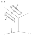
- Fig. 9 is showing installation status of a lighting module 400 according to the present invention, and the lighting module can be installed to the surface of a wall or ceiling.
- the installed surface and the case 200 or the lighting module 400 are a predetermined distant apart by the end cap 350 being bent towards the rear side of the lighting module 400.
- the secured space as such can be used for placing a ballast stabilizer or can include heat radiating structure having a volume not exceeding the space to help heat radiation of the inner light source of the lighting module 400.
- the lighting module can be installed to the ceiling in pendent form as Fig. 10 .
- a plurality of the lighting modules 400 can be connected by using predetermined connection member (not shown) and a receiving recess 351a, and can be used as an extended form by connecting the end cap 350 to the both ends when it reached the intended length.
Landscapes
- Physics & Mathematics (AREA)
- General Physics & Mathematics (AREA)
- Optics & Photonics (AREA)
- Engineering & Computer Science (AREA)
- General Engineering & Computer Science (AREA)
- Non-Portable Lighting Devices Or Systems Thereof (AREA)
- Planar Illumination Modules (AREA)
- Arrangement Of Elements, Cooling, Sealing, Or The Like Of Lighting Devices (AREA)
- Fastening Of Light Sources Or Lamp Holders (AREA)
Priority Applications (1)
| Application Number | Priority Date | Filing Date | Title |
|---|---|---|---|
| EP13174944.2A EP2648024B1 (de) | 2010-04-10 | 2011-04-06 | Leuchtmodul und Leuchte mit selbigem |
Applications Claiming Priority (5)
| Application Number | Priority Date | Filing Date | Title |
|---|---|---|---|
| KR1020100033051A KR101652833B1 (ko) | 2010-04-10 | 2010-04-10 | 조명장치 |
| KR1020100033030A KR101652012B1 (ko) | 2010-04-10 | 2010-04-10 | 조명 모듈 |
| KR1020100033031A KR101694996B1 (ko) | 2010-04-10 | 2010-04-10 | 조명 장치 |
| KR1020100092982A KR101798565B1 (ko) | 2010-09-27 | 2010-09-27 | 조명 모듈 |
| KR1020100122751A KR101810920B1 (ko) | 2010-12-03 | 2010-12-03 | 조명 모듈 |
Related Child Applications (2)
| Application Number | Title | Priority Date | Filing Date |
|---|---|---|---|
| EP13174944.2A Division EP2648024B1 (de) | 2010-04-10 | 2011-04-06 | Leuchtmodul und Leuchte mit selbigem |
| EP13174944.2 Division-Into | 2013-07-03 |
Publications (3)
| Publication Number | Publication Date |
|---|---|
| EP2375137A2 true EP2375137A2 (de) | 2011-10-12 |
| EP2375137A3 EP2375137A3 (de) | 2011-11-02 |
| EP2375137B1 EP2375137B1 (de) | 2013-08-28 |
Family
ID=44201096
Family Applications (2)
| Application Number | Title | Priority Date | Filing Date |
|---|---|---|---|
| EP11161333.7A Not-in-force EP2375137B1 (de) | 2010-04-10 | 2011-04-06 | Beleuchtungsmodul und Beleuchtungsvorrichtung damit |
| EP13174944.2A Active EP2648024B1 (de) | 2010-04-10 | 2011-04-06 | Leuchtmodul und Leuchte mit selbigem |
Family Applications After (1)
| Application Number | Title | Priority Date | Filing Date |
|---|---|---|---|
| EP13174944.2A Active EP2648024B1 (de) | 2010-04-10 | 2011-04-06 | Leuchtmodul und Leuchte mit selbigem |
Country Status (4)
| Country | Link |
|---|---|
| US (2) | US8231258B2 (de) |
| EP (2) | EP2375137B1 (de) |
| JP (2) | JP5755484B2 (de) |
| CN (2) | CN102252180A (de) |
Cited By (1)
| Publication number | Priority date | Publication date | Assignee | Title |
|---|---|---|---|---|
| CN104676500A (zh) * | 2013-11-26 | 2015-06-03 | 潘文莘 | 一种导光单元及具有该导光单元的发光装置 |
Families Citing this family (58)
| Publication number | Priority date | Publication date | Assignee | Title |
|---|---|---|---|---|
| US8231258B2 (en) * | 2010-04-10 | 2012-07-31 | Lg Innotek Co., Ltd. | Lighting module and lighting apparatus including the same |
| EP2431654B1 (de) | 2010-09-17 | 2018-11-14 | LG Innotek Co., Ltd. | Beleuchtungsmodul und Beleuchtungsvorrichtung |
| US9563008B2 (en) | 2010-09-17 | 2017-02-07 | Lg Innotek Co., Ltd. | Lighting module and lighting apparatus including the same |
| US8192051B2 (en) * | 2010-11-01 | 2012-06-05 | Quarkstar Llc | Bidirectional LED light sheet |
| US8314566B2 (en) | 2011-02-22 | 2012-11-20 | Quarkstar Llc | Solid state lamp using light emitting strips |
| US8410726B2 (en) | 2011-02-22 | 2013-04-02 | Quarkstar Llc | Solid state lamp using modular light emitting elements |
| USRE48690E1 (en) | 2011-09-09 | 2021-08-17 | Lg Innotek Co., Ltd. | Light unit and a LCD liquid crystal display comprising the light unit |
| JP5716623B2 (ja) * | 2011-09-27 | 2015-05-13 | 豊田合成株式会社 | 線状光源装置および面状光源装置 |
| FR2981434B1 (fr) * | 2011-10-14 | 2017-12-01 | Oya Sourcing | Luminaire |
| CN103574355B (zh) * | 2012-08-10 | 2017-11-17 | Lg伊诺特有限公司 | 照明装置 |
| US9188318B2 (en) * | 2012-09-12 | 2015-11-17 | Cooper Technologies Company | Light-emitting diode wave guide down light retrofit fixtures |
| WO2014043138A1 (en) | 2012-09-12 | 2014-03-20 | Cooper Technologies Company | Light-emitting diode light retrofit fixtures |
| JP2014063600A (ja) | 2012-09-20 | 2014-04-10 | Mitsubishi Electric Corp | 線状光源装置 |
| CN103836436A (zh) * | 2012-11-21 | 2014-06-04 | 深圳市海洋王照明工程有限公司 | 灯具 |
| CN103836438A (zh) * | 2012-11-21 | 2014-06-04 | 深圳市海洋王照明工程有限公司 | 灯具 |
| USD706483S1 (en) * | 2012-11-27 | 2014-06-03 | Johnson Wai Aquarium Supply Co., Ltd. | Light |
| CN103104843B (zh) * | 2013-01-24 | 2015-03-25 | 杭州纳晶照明技术有限公司 | 照明装置 |
| US9291320B2 (en) | 2013-01-30 | 2016-03-22 | Cree, Inc. | Consolidated troffer |
| US9625638B2 (en) | 2013-03-15 | 2017-04-18 | Cree, Inc. | Optical waveguide body |
| US9690029B2 (en) | 2013-01-30 | 2017-06-27 | Cree, Inc. | Optical waveguides and luminaires incorporating same |
| US9366396B2 (en) | 2013-01-30 | 2016-06-14 | Cree, Inc. | Optical waveguide and lamp including same |
| US9442243B2 (en) | 2013-01-30 | 2016-09-13 | Cree, Inc. | Waveguide bodies including redirection features and methods of producing same |
| US9869432B2 (en) | 2013-01-30 | 2018-01-16 | Cree, Inc. | Luminaires using waveguide bodies and optical elements |
| US9581751B2 (en) | 2013-01-30 | 2017-02-28 | Cree, Inc. | Optical waveguide and lamp including same |
| EP2767753A1 (de) * | 2013-02-18 | 2014-08-20 | LD Lichtdominanz GmbH | Auf der Basis von Leuchtdioden-Chips arbeitendes Lichtpanel |
| US10209429B2 (en) | 2013-03-15 | 2019-02-19 | Cree, Inc. | Luminaire with selectable luminous intensity pattern |
| US10400984B2 (en) | 2013-03-15 | 2019-09-03 | Cree, Inc. | LED light fixture and unitary optic member therefor |
| US10379278B2 (en) * | 2013-03-15 | 2019-08-13 | Ideal Industries Lighting Llc | Outdoor and/or enclosed structure LED luminaire outdoor and/or enclosed structure LED luminaire having outward illumination |
| US9645303B2 (en) | 2013-03-15 | 2017-05-09 | Cree, Inc. | Luminaires utilizing edge coupling |
| US9366799B2 (en) | 2013-03-15 | 2016-06-14 | Cree, Inc. | Optical waveguide bodies and luminaires utilizing same |
| US10436970B2 (en) | 2013-03-15 | 2019-10-08 | Ideal Industries Lighting Llc | Shaped optical waveguide bodies |
| US9920901B2 (en) | 2013-03-15 | 2018-03-20 | Cree, Inc. | LED lensing arrangement |
| US9798072B2 (en) | 2013-03-15 | 2017-10-24 | Cree, Inc. | Optical element and method of forming an optical element |
| US10502899B2 (en) * | 2013-03-15 | 2019-12-10 | Ideal Industries Lighting Llc | Outdoor and/or enclosed structure LED luminaire |
| US10036517B2 (en) * | 2013-05-16 | 2018-07-31 | 3M Innovative Properties Company | Lightguide as luminaire |
| USD717990S1 (en) * | 2013-10-03 | 2014-11-18 | Nitto Denko Corporation | Organic light emitting diode device |
| USD751237S1 (en) * | 2014-04-30 | 2016-03-08 | Pinnacle Architectural Lighting | Suspended light fixture |
| US10288263B2 (en) * | 2014-08-08 | 2019-05-14 | Kaneka Corporation | Planar light-emitting panel and elastic jacket |
| USD792016S1 (en) * | 2015-03-31 | 2017-07-11 | Artemide S.P.A. | Lighting fixture |
| USD782722S1 (en) * | 2015-07-20 | 2017-03-28 | Hubbardton Forge, Llc. | Lamp |
| US9964692B2 (en) * | 2015-10-06 | 2018-05-08 | Focal Point, Llc | Illuminated feature for an LED luminaire |
| WO2020073318A1 (zh) * | 2018-10-12 | 2020-04-16 | 瑞仪光电(苏州)有限公司 | 灯具、灯具系统、及灯具系统的组装方法 |
| CN106885186B (zh) * | 2015-12-15 | 2019-03-15 | 瑞仪光电(苏州)有限公司 | 灯具 |
| US11759993B2 (en) | 2016-01-20 | 2023-09-19 | Nissan Ringel | Panel device and method of manufacturing |
| US20190261788A1 (en) * | 2016-01-20 | 2019-08-29 | Nissan Ringel | Lighting Units |
| US11719882B2 (en) | 2016-05-06 | 2023-08-08 | Ideal Industries Lighting Llc | Waveguide-based light sources with dynamic beam shaping |
| US10416377B2 (en) | 2016-05-06 | 2019-09-17 | Cree, Inc. | Luminaire with controllable light emission |
| CN206975364U (zh) * | 2016-07-22 | 2018-02-06 | 矽创电子股份有限公司 | 显示设备及其具光路弯折的背光装置 |
| US11680699B2 (en) | 2018-10-12 | 2023-06-20 | Radiant Opto-Electronics (Suzhou) Co., Ltd. | Lamp, lamp system, method for assembling lamp system, and method for disassembling lamp system |
| US10775018B1 (en) * | 2019-09-17 | 2020-09-15 | Abl Ip Holding Llc | Direct/indirect luminaire systems and methods |
| CN110675741B (zh) * | 2019-09-29 | 2021-10-08 | 厦门天马微电子有限公司 | 背光模组和显示装置 |
| NL2024980B1 (en) * | 2020-02-24 | 2021-10-14 | Schreder Sa | Modular luminaire assemblies for tunnels |
| EP3875840B1 (de) * | 2020-03-03 | 2022-06-29 | Prosperous (Ningbo) Lighting Appliance Co., Ltd. | Unabhängige und spleissbare schranklampe |
| CN111750321A (zh) * | 2020-06-24 | 2020-10-09 | 上海摩勤智能技术有限公司 | 可发光组件、壳体及电子设备 |
| CN111623302A (zh) * | 2020-06-29 | 2020-09-04 | 欧普照明股份有限公司 | 照明灯具 |
| WO2022001956A1 (zh) * | 2020-06-29 | 2022-01-06 | 苏州欧普照明有限公司 | 照明灯具 |
| TWI749713B (zh) * | 2020-08-14 | 2021-12-11 | 群光電能科技股份有限公司 | 背光模組及其發光觸控裝置 |
| WO2022116928A1 (zh) * | 2020-12-04 | 2022-06-09 | 苏州欧普照明有限公司 | 照明灯具 |
Family Cites Families (44)
| Publication number | Priority date | Publication date | Assignee | Title |
|---|---|---|---|---|
| DE19644875A1 (de) | 1996-10-29 | 1998-04-30 | Willing Gmbh Dr Ing | Großflächenleuchte |
| DE19755658A1 (de) | 1997-12-15 | 1999-06-17 | Zumtobel Staff Gmbh | Leuchte mit einem scheibenförmigen Lichtleiter |
| JP3114805B2 (ja) * | 1998-04-15 | 2000-12-04 | 日亜化学工業株式会社 | 面状光源及びそれを用いたディスプレイのバックライト、照光式操作スイッチ |
| JP2000207917A (ja) * | 1999-01-14 | 2000-07-28 | Samsung Electronics Co Ltd | 液晶表示装置モジュ―ル用バックライトアセンブリ |
| JP3792498B2 (ja) * | 2000-10-26 | 2006-07-05 | 株式会社エンプラス | 面光源装置及び画像表示装置 |
| ES2232680T3 (es) | 2000-12-22 | 2005-06-01 | Thomas Emde | Elemento de placa tipo sandwich. |
| JP2003203515A (ja) * | 2002-01-09 | 2003-07-18 | Sharp Corp | 照明装置、照明装置の設計方法、照明装置の製造方法、表示装置および導光体 |
| JP4130100B2 (ja) * | 2002-07-05 | 2008-08-06 | アルプス電気株式会社 | 面発光装置及び液晶表示装置 |
| WO2004027314A1 (ja) * | 2002-09-19 | 2004-04-01 | Matsushita Electric Industrial Co., Ltd. | 照明ユニット及びそれを用いた液晶表示装置 |
| KR100962641B1 (ko) * | 2003-07-07 | 2010-06-11 | 삼성전자주식회사 | 백라이트 어셈블리와 이를 갖는 액정 표시 장치 및 백라이트 어셈블리의 제조 방법 |
| JP2005339881A (ja) * | 2004-05-25 | 2005-12-08 | Hitachi Displays Ltd | 照明装置、照明モジュール及び液晶表示装置 |
| CN100395623C (zh) * | 2005-06-10 | 2008-06-18 | 清华大学 | 背光模组 |
| TWI288852B (en) * | 2005-07-22 | 2007-10-21 | Innolux Display Corp | Backlight module and liquid crystal display device using the same |
| CA2626448C (en) * | 2005-10-26 | 2010-11-30 | Fawoo Technology Co., Ltd. | Backlight unit capable of easily forming curved and three-dimensional shape |
| EP1942302A1 (de) * | 2005-10-28 | 2008-07-09 | Takiron Co., Ltd. | Oberflächenemissionsvorrichtung und lichtemissionsverfahren für eine oberflächenemissionsvorrichtung |
| US20070127144A1 (en) * | 2005-12-06 | 2007-06-07 | Eastman Kodak Company | Optical film and frame with high resistance to thermal distortion |
| US7547112B2 (en) | 2005-12-12 | 2009-06-16 | Led Folio Corporation | Low-clearance light emitting diode lighting |
| CN101331356B (zh) * | 2005-12-16 | 2012-04-25 | 皇家飞利浦电子股份有限公司 | 包括可相互连接的照明模块的照明系统 |
| JP2007178797A (ja) * | 2005-12-28 | 2007-07-12 | Optrex Corp | 液晶表示装置 |
| JP4659640B2 (ja) * | 2006-02-24 | 2011-03-30 | オスラム・メルコ株式会社 | 発光ダイオードを利用した照明器具 |
| WO2007115736A1 (de) | 2006-04-04 | 2007-10-18 | Thomas Emde | Beleuchtbare plattenanordnung |
| US20080037284A1 (en) | 2006-04-21 | 2008-02-14 | Rudisill Charles A | Lightguide tile modules and modular lighting system |
| JP4388042B2 (ja) * | 2006-08-11 | 2009-12-24 | 勝華科技股▲ふん▼有限公司 | 液晶ディスプレイ及びそのフレーム |
| JP2008066143A (ja) * | 2006-09-07 | 2008-03-21 | Nidec Copal Corp | 面発光装置 |
| WO2008041185A2 (en) | 2006-10-05 | 2008-04-10 | Koninklijke Philips Electronics N.V. | Lighting device comprising a light tile with variable color temperature |
| JP2008175926A (ja) * | 2007-01-17 | 2008-07-31 | Hitachi Displays Ltd | 液晶表示モジュール |
| JP4973213B2 (ja) * | 2007-01-31 | 2012-07-11 | 三菱電機株式会社 | 光源装置、面状光源装置および表示装置 |
| KR101283129B1 (ko) * | 2007-04-03 | 2013-07-05 | 엘지이노텍 주식회사 | 도광판, 면 광원 장치 및 이를 갖는 표시 장치 |
| US20090010022A1 (en) * | 2007-07-03 | 2009-01-08 | Tsai Tzung-Shiun | Multi-functional led lamp |
| US20090086504A1 (en) | 2007-10-02 | 2009-04-02 | Led Folio Corporation | Backlit erasable writing board |
| JP2009117235A (ja) * | 2007-11-08 | 2009-05-28 | Yamaha Motor Electronics Co Ltd | バックライトモジュールおよびデジタルメーター |
| US7549784B1 (en) | 2007-12-06 | 2009-06-23 | New Horizon Designs, Inc. | LED lighting for glass tiles |
| JP5168626B2 (ja) * | 2008-01-16 | 2013-03-21 | 日本精機株式会社 | バックライト装置 |
| JP2009199924A (ja) * | 2008-02-22 | 2009-09-03 | Okamura Corp | 照明装置 |
| US20090237958A1 (en) | 2008-03-21 | 2009-09-24 | Led Folio Corporation | Low-clearance light-emitting diode lighting |
| JP5149668B2 (ja) * | 2008-03-26 | 2013-02-20 | パナソニック株式会社 | 照明器具の取付装置 |
| CN101603665A (zh) * | 2008-06-13 | 2009-12-16 | 先进开发光电股份有限公司 | 发光二极管光源模块 |
| EP2161600A1 (de) * | 2008-09-09 | 2010-03-10 | TPO Displays Corp. | Flüssigkristallanzeigevorrichtung mit Lichtwellenleiter |
| DE102008047010A1 (de) | 2008-09-12 | 2010-03-18 | Zumtobel Lighting Gmbh | System zur Aufhellung der Decke eines Raumes |
| TWI394921B (zh) | 2008-09-22 | 2013-05-01 | Sinology Entpr Ltd | 具模組化光源之燈箱結構及其模組化光源結構 |
| CN101684926A (zh) * | 2008-09-26 | 2010-03-31 | 上海莹亮照明科技有限公司 | Led导光板 |
| CN201434302Y (zh) * | 2009-05-07 | 2010-03-31 | 陈铿胜 | 高位刹车灯 |
| CN201425205Y (zh) * | 2009-05-21 | 2010-03-17 | 潘文莘 | 能够产生均匀条状光源的发光二极管照明装置及照明模块 |
| US8231258B2 (en) * | 2010-04-10 | 2012-07-31 | Lg Innotek Co., Ltd. | Lighting module and lighting apparatus including the same |
-
2011
- 2011-04-05 US US13/080,440 patent/US8231258B2/en not_active Expired - Fee Related
- 2011-04-06 EP EP11161333.7A patent/EP2375137B1/de not_active Not-in-force
- 2011-04-06 EP EP13174944.2A patent/EP2648024B1/de active Active
- 2011-04-08 JP JP2011085860A patent/JP5755484B2/ja not_active Expired - Fee Related
- 2011-04-11 CN CN2011100923821A patent/CN102252180A/zh active Pending
- 2011-04-11 CN CN201510555698.8A patent/CN105065952B/zh active Active
-
2012
- 2012-05-15 US US13/471,967 patent/US8382354B2/en not_active Expired - Fee Related
-
2015
- 2015-05-27 JP JP2015107785A patent/JP6189361B2/ja active Active
Non-Patent Citations (1)
| Title |
|---|
| None |
Cited By (1)
| Publication number | Priority date | Publication date | Assignee | Title |
|---|---|---|---|---|
| CN104676500A (zh) * | 2013-11-26 | 2015-06-03 | 潘文莘 | 一种导光单元及具有该导光单元的发光装置 |
Also Published As
| Publication number | Publication date |
|---|---|
| JP2011222516A (ja) | 2011-11-04 |
| US20110205758A1 (en) | 2011-08-25 |
| US8382354B2 (en) | 2013-02-26 |
| EP2375137B1 (de) | 2013-08-28 |
| EP2648024B1 (de) | 2022-10-26 |
| CN105065952B (zh) | 2019-01-11 |
| JP5755484B2 (ja) | 2015-07-29 |
| EP2375137A3 (de) | 2011-11-02 |
| EP2648024A3 (de) | 2014-01-08 |
| EP2648024A2 (de) | 2013-10-09 |
| JP6189361B2 (ja) | 2017-08-30 |
| US20120224392A1 (en) | 2012-09-06 |
| CN102252180A (zh) | 2011-11-23 |
| US8231258B2 (en) | 2012-07-31 |
| JP2015179681A (ja) | 2015-10-08 |
| CN105065952A (zh) | 2015-11-18 |
Similar Documents
| Publication | Publication Date | Title |
|---|---|---|
| EP2375137B1 (de) | Beleuchtungsmodul und Beleuchtungsvorrichtung damit | |
| US8573823B2 (en) | Solid-state luminaire | |
| WO2010001604A1 (ja) | 照明装置 | |
| EP2314911A2 (de) | Lichtquellenvorrichtung | |
| WO2013128761A1 (ja) | 照明モジュールおよびそれを備えた照明装置 | |
| US9605814B2 (en) | Lighting module | |
| JP2007234385A (ja) | バックライト装置 | |
| WO2018196564A1 (zh) | 一种发光模组及应用该发光模组的照明装置 | |
| KR20220098713A (ko) | 조명 장치 | |
| KR101780426B1 (ko) | 조명 모듈 | |
| KR101683586B1 (ko) | 조명 모듈 결합용 접속 장치 및 이를 포함하는 조명 장치 | |
| KR101652012B1 (ko) | 조명 모듈 | |
| KR101810920B1 (ko) | 조명 모듈 | |
| KR101788840B1 (ko) | 조명 모듈 | |
| KR101824150B1 (ko) | 조명 장치 | |
| KR101815135B1 (ko) | 조명 모듈 | |
| KR101694996B1 (ko) | 조명 장치 | |
| KR101798565B1 (ko) | 조명 모듈 | |
| KR101272689B1 (ko) | 조명 모듈 | |
| KR20120069837A (ko) | 조명 모듈 | |
| KR20120052525A (ko) | 조명 모듈 | |
| KR20130044621A (ko) | 조명 모듈 | |
| KR20150089246A (ko) | 조명장치 및 이를 포함하는 차량용 램프 |
Legal Events
| Date | Code | Title | Description |
|---|---|---|---|
| PUAI | Public reference made under article 153(3) epc to a published international application that has entered the european phase |
Free format text: ORIGINAL CODE: 0009012 |
|
| PUAL | Search report despatched |
Free format text: ORIGINAL CODE: 0009013 |
|
| 17P | Request for examination filed |
Effective date: 20110406 |
|
| AK | Designated contracting states |
Kind code of ref document: A2 Designated state(s): AL AT BE BG CH CY CZ DE DK EE ES FI FR GB GR HR HU IE IS IT LI LT LU LV MC MK MT NL NO PL PT RO RS SE SI SK SM TR |
|
| AX | Request for extension of the european patent |
Extension state: BA ME |
|
| AK | Designated contracting states |
Kind code of ref document: A3 Designated state(s): AL AT BE BG CH CY CZ DE DK EE ES FI FR GB GR HR HU IE IS IT LI LT LU LV MC MK MT NL NO PL PT RO RS SE SI SK SM TR |
|
| AX | Request for extension of the european patent |
Extension state: BA ME |
|
| RIC1 | Information provided on ipc code assigned before grant |
Ipc: F21S 10/00 20060101AFI20110928BHEP Ipc: G02B 6/00 20060101ALI20110928BHEP |
|
| 17Q | First examination report despatched |
Effective date: 20120717 |
|
| GRAP | Despatch of communication of intention to grant a patent |
Free format text: ORIGINAL CODE: EPIDOSNIGR1 |
|
| GRAS | Grant fee paid |
Free format text: ORIGINAL CODE: EPIDOSNIGR3 |
|
| GRAA | (expected) grant |
Free format text: ORIGINAL CODE: 0009210 |
|
| AK | Designated contracting states |
Kind code of ref document: B1 Designated state(s): AL AT BE BG CH CY CZ DE DK EE ES FI FR GB GR HR HU IE IS IT LI LT LU LV MC MK MT NL NO PL PT RO RS SE SI SK SM TR |
|
| REG | Reference to a national code |
Ref country code: GB Ref legal event code: FG4D |
|
| REG | Reference to a national code |
Ref country code: CH Ref legal event code: EP |
|
| REG | Reference to a national code |
Ref country code: AT Ref legal event code: REF Ref document number: 629565 Country of ref document: AT Kind code of ref document: T Effective date: 20130915 |
|
| REG | Reference to a national code |
Ref country code: IE Ref legal event code: FG4D |
|
| REG | Reference to a national code |
Ref country code: DE Ref legal event code: R096 Ref document number: 602011002779 Country of ref document: DE Effective date: 20131024 |
|
| REG | Reference to a national code |
Ref country code: NL Ref legal event code: T3 |
|
| REG | Reference to a national code |
Ref country code: AT Ref legal event code: MK05 Ref document number: 629565 Country of ref document: AT Kind code of ref document: T Effective date: 20130828 |
|
| REG | Reference to a national code |
Ref country code: LT Ref legal event code: MG4D |
|
| PG25 | Lapsed in a contracting state [announced via postgrant information from national office to epo] |
Ref country code: IS Free format text: LAPSE BECAUSE OF FAILURE TO SUBMIT A TRANSLATION OF THE DESCRIPTION OR TO PAY THE FEE WITHIN THE PRESCRIBED TIME-LIMIT Effective date: 20131228 Ref country code: SE Free format text: LAPSE BECAUSE OF FAILURE TO SUBMIT A TRANSLATION OF THE DESCRIPTION OR TO PAY THE FEE WITHIN THE PRESCRIBED TIME-LIMIT Effective date: 20130828 Ref country code: NO Free format text: LAPSE BECAUSE OF FAILURE TO SUBMIT A TRANSLATION OF THE DESCRIPTION OR TO PAY THE FEE WITHIN THE PRESCRIBED TIME-LIMIT Effective date: 20131128 Ref country code: HR Free format text: LAPSE BECAUSE OF FAILURE TO SUBMIT A TRANSLATION OF THE DESCRIPTION OR TO PAY THE FEE WITHIN THE PRESCRIBED TIME-LIMIT Effective date: 20130828 Ref country code: LT Free format text: LAPSE BECAUSE OF FAILURE TO SUBMIT A TRANSLATION OF THE DESCRIPTION OR TO PAY THE FEE WITHIN THE PRESCRIBED TIME-LIMIT Effective date: 20130828 Ref country code: PT Free format text: LAPSE BECAUSE OF FAILURE TO SUBMIT A TRANSLATION OF THE DESCRIPTION OR TO PAY THE FEE WITHIN THE PRESCRIBED TIME-LIMIT Effective date: 20131230 Ref country code: CY Free format text: LAPSE BECAUSE OF FAILURE TO SUBMIT A TRANSLATION OF THE DESCRIPTION OR TO PAY THE FEE WITHIN THE PRESCRIBED TIME-LIMIT Effective date: 20130619 Ref country code: AT Free format text: LAPSE BECAUSE OF FAILURE TO SUBMIT A TRANSLATION OF THE DESCRIPTION OR TO PAY THE FEE WITHIN THE PRESCRIBED TIME-LIMIT Effective date: 20130828 |
|
| PG25 | Lapsed in a contracting state [announced via postgrant information from national office to epo] |
Ref country code: LV Free format text: LAPSE BECAUSE OF FAILURE TO SUBMIT A TRANSLATION OF THE DESCRIPTION OR TO PAY THE FEE WITHIN THE PRESCRIBED TIME-LIMIT Effective date: 20130828 Ref country code: BE Free format text: LAPSE BECAUSE OF FAILURE TO SUBMIT A TRANSLATION OF THE DESCRIPTION OR TO PAY THE FEE WITHIN THE PRESCRIBED TIME-LIMIT Effective date: 20130828 Ref country code: GR Free format text: LAPSE BECAUSE OF FAILURE TO SUBMIT A TRANSLATION OF THE DESCRIPTION OR TO PAY THE FEE WITHIN THE PRESCRIBED TIME-LIMIT Effective date: 20131129 Ref country code: PL Free format text: LAPSE BECAUSE OF FAILURE TO SUBMIT A TRANSLATION OF THE DESCRIPTION OR TO PAY THE FEE WITHIN THE PRESCRIBED TIME-LIMIT Effective date: 20130828 Ref country code: SI Free format text: LAPSE BECAUSE OF FAILURE TO SUBMIT A TRANSLATION OF THE DESCRIPTION OR TO PAY THE FEE WITHIN THE PRESCRIBED TIME-LIMIT Effective date: 20130828 Ref country code: FI Free format text: LAPSE BECAUSE OF FAILURE TO SUBMIT A TRANSLATION OF THE DESCRIPTION OR TO PAY THE FEE WITHIN THE PRESCRIBED TIME-LIMIT Effective date: 20130828 |
|
| PG25 | Lapsed in a contracting state [announced via postgrant information from national office to epo] |
Ref country code: CY Free format text: LAPSE BECAUSE OF FAILURE TO SUBMIT A TRANSLATION OF THE DESCRIPTION OR TO PAY THE FEE WITHIN THE PRESCRIBED TIME-LIMIT Effective date: 20130828 |
|
| PG25 | Lapsed in a contracting state [announced via postgrant information from national office to epo] |
Ref country code: RO Free format text: LAPSE BECAUSE OF FAILURE TO SUBMIT A TRANSLATION OF THE DESCRIPTION OR TO PAY THE FEE WITHIN THE PRESCRIBED TIME-LIMIT Effective date: 20130828 Ref country code: CZ Free format text: LAPSE BECAUSE OF FAILURE TO SUBMIT A TRANSLATION OF THE DESCRIPTION OR TO PAY THE FEE WITHIN THE PRESCRIBED TIME-LIMIT Effective date: 20130828 Ref country code: DK Free format text: LAPSE BECAUSE OF FAILURE TO SUBMIT A TRANSLATION OF THE DESCRIPTION OR TO PAY THE FEE WITHIN THE PRESCRIBED TIME-LIMIT Effective date: 20130828 Ref country code: SK Free format text: LAPSE BECAUSE OF FAILURE TO SUBMIT A TRANSLATION OF THE DESCRIPTION OR TO PAY THE FEE WITHIN THE PRESCRIBED TIME-LIMIT Effective date: 20130828 Ref country code: EE Free format text: LAPSE BECAUSE OF FAILURE TO SUBMIT A TRANSLATION OF THE DESCRIPTION OR TO PAY THE FEE WITHIN THE PRESCRIBED TIME-LIMIT Effective date: 20130828 |
|
| PG25 | Lapsed in a contracting state [announced via postgrant information from national office to epo] |
Ref country code: ES Free format text: LAPSE BECAUSE OF FAILURE TO SUBMIT A TRANSLATION OF THE DESCRIPTION OR TO PAY THE FEE WITHIN THE PRESCRIBED TIME-LIMIT Effective date: 20130828 Ref country code: IT Free format text: LAPSE BECAUSE OF FAILURE TO SUBMIT A TRANSLATION OF THE DESCRIPTION OR TO PAY THE FEE WITHIN THE PRESCRIBED TIME-LIMIT Effective date: 20130828 |
|
| REG | Reference to a national code |
Ref country code: DE Ref legal event code: R097 Ref document number: 602011002779 Country of ref document: DE |
|
| PLBE | No opposition filed within time limit |
Free format text: ORIGINAL CODE: 0009261 |
|
| STAA | Information on the status of an ep patent application or granted ep patent |
Free format text: STATUS: NO OPPOSITION FILED WITHIN TIME LIMIT |
|
| 26N | No opposition filed |
Effective date: 20140530 |
|
| REG | Reference to a national code |
Ref country code: DE Ref legal event code: R097 Ref document number: 602011002779 Country of ref document: DE Effective date: 20140530 |
|
| PG25 | Lapsed in a contracting state [announced via postgrant information from national office to epo] |
Ref country code: MC Free format text: LAPSE BECAUSE OF FAILURE TO SUBMIT A TRANSLATION OF THE DESCRIPTION OR TO PAY THE FEE WITHIN THE PRESCRIBED TIME-LIMIT Effective date: 20130828 Ref country code: LU Free format text: LAPSE BECAUSE OF FAILURE TO SUBMIT A TRANSLATION OF THE DESCRIPTION OR TO PAY THE FEE WITHIN THE PRESCRIBED TIME-LIMIT Effective date: 20140406 |
|
| REG | Reference to a national code |
Ref country code: CH Ref legal event code: PL |
|
| REG | Reference to a national code |
Ref country code: IE Ref legal event code: MM4A |
|
| PG25 | Lapsed in a contracting state [announced via postgrant information from national office to epo] |
Ref country code: CH Free format text: LAPSE BECAUSE OF NON-PAYMENT OF DUE FEES Effective date: 20140430 Ref country code: LI Free format text: LAPSE BECAUSE OF NON-PAYMENT OF DUE FEES Effective date: 20140430 |
|
| PG25 | Lapsed in a contracting state [announced via postgrant information from national office to epo] |
Ref country code: IE Free format text: LAPSE BECAUSE OF NON-PAYMENT OF DUE FEES Effective date: 20140406 |
|
| REG | Reference to a national code |
Ref country code: FR Ref legal event code: PLFP Year of fee payment: 6 |
|
| PG25 | Lapsed in a contracting state [announced via postgrant information from national office to epo] |
Ref country code: MT Free format text: LAPSE BECAUSE OF FAILURE TO SUBMIT A TRANSLATION OF THE DESCRIPTION OR TO PAY THE FEE WITHIN THE PRESCRIBED TIME-LIMIT Effective date: 20130828 |
|
| PG25 | Lapsed in a contracting state [announced via postgrant information from national office to epo] |
Ref country code: SM Free format text: LAPSE BECAUSE OF FAILURE TO SUBMIT A TRANSLATION OF THE DESCRIPTION OR TO PAY THE FEE WITHIN THE PRESCRIBED TIME-LIMIT Effective date: 20130828 |
|
| PG25 | Lapsed in a contracting state [announced via postgrant information from national office to epo] |
Ref country code: BG Free format text: LAPSE BECAUSE OF FAILURE TO SUBMIT A TRANSLATION OF THE DESCRIPTION OR TO PAY THE FEE WITHIN THE PRESCRIBED TIME-LIMIT Effective date: 20130828 Ref country code: RS Free format text: LAPSE BECAUSE OF FAILURE TO SUBMIT A TRANSLATION OF THE DESCRIPTION OR TO PAY THE FEE WITHIN THE PRESCRIBED TIME-LIMIT Effective date: 20130828 |
|
| PG25 | Lapsed in a contracting state [announced via postgrant information from national office to epo] |
Ref country code: HU Free format text: LAPSE BECAUSE OF FAILURE TO SUBMIT A TRANSLATION OF THE DESCRIPTION OR TO PAY THE FEE WITHIN THE PRESCRIBED TIME-LIMIT; INVALID AB INITIO Effective date: 20110406 Ref country code: TR Free format text: LAPSE BECAUSE OF FAILURE TO SUBMIT A TRANSLATION OF THE DESCRIPTION OR TO PAY THE FEE WITHIN THE PRESCRIBED TIME-LIMIT Effective date: 20130828 |
|
| REG | Reference to a national code |
Ref country code: FR Ref legal event code: PLFP Year of fee payment: 7 |
|
| PGFP | Annual fee paid to national office [announced via postgrant information from national office to epo] |
Ref country code: NL Payment date: 20170308 Year of fee payment: 7 Ref country code: FR Payment date: 20170309 Year of fee payment: 7 |
|
| PG25 | Lapsed in a contracting state [announced via postgrant information from national office to epo] |
Ref country code: MK Free format text: LAPSE BECAUSE OF FAILURE TO SUBMIT A TRANSLATION OF THE DESCRIPTION OR TO PAY THE FEE WITHIN THE PRESCRIBED TIME-LIMIT Effective date: 20130828 |
|
| PG25 | Lapsed in a contracting state [announced via postgrant information from national office to epo] |
Ref country code: AL Free format text: LAPSE BECAUSE OF FAILURE TO SUBMIT A TRANSLATION OF THE DESCRIPTION OR TO PAY THE FEE WITHIN THE PRESCRIBED TIME-LIMIT Effective date: 20130828 |
|
| REG | Reference to a national code |
Ref country code: NL Ref legal event code: MM Effective date: 20180501 |
|
| PG25 | Lapsed in a contracting state [announced via postgrant information from national office to epo] |
Ref country code: NL Free format text: LAPSE BECAUSE OF NON-PAYMENT OF DUE FEES Effective date: 20180501 |
|
| PG25 | Lapsed in a contracting state [announced via postgrant information from national office to epo] |
Ref country code: FR Free format text: LAPSE BECAUSE OF NON-PAYMENT OF DUE FEES Effective date: 20180430 |
|
| REG | Reference to a national code |
Ref country code: GB Ref legal event code: 732E Free format text: REGISTERED BETWEEN 20210722 AND 20210728 |
|
| REG | Reference to a national code |
Ref country code: DE Ref legal event code: R081 Ref document number: 602011002779 Country of ref document: DE Owner name: SUZHOU LEKIN SEMICONDUCTOR CO. LTD., TAICANG, CN Free format text: FORMER OWNER: LG INNOTEK CO., LTD., SEOUL/SOUL, KR |
|
| PGFP | Annual fee paid to national office [announced via postgrant information from national office to epo] |
Ref country code: GB Payment date: 20230309 Year of fee payment: 13 |
|
| PGFP | Annual fee paid to national office [announced via postgrant information from national office to epo] |
Ref country code: DE Payment date: 20230314 Year of fee payment: 13 |
|
| REG | Reference to a national code |
Ref country code: DE Ref legal event code: R119 Ref document number: 602011002779 Country of ref document: DE |
|
| GBPC | Gb: european patent ceased through non-payment of renewal fee |
Effective date: 20240406 |
|
| PG25 | Lapsed in a contracting state [announced via postgrant information from national office to epo] |
Ref country code: DE Free format text: LAPSE BECAUSE OF NON-PAYMENT OF DUE FEES Effective date: 20241105 |
|
| PG25 | Lapsed in a contracting state [announced via postgrant information from national office to epo] |
Ref country code: GB Free format text: LAPSE BECAUSE OF NON-PAYMENT OF DUE FEES Effective date: 20240406 |
|
| PG25 | Lapsed in a contracting state [announced via postgrant information from national office to epo] |
Ref country code: GB Free format text: LAPSE BECAUSE OF NON-PAYMENT OF DUE FEES Effective date: 20240406 Ref country code: DE Free format text: LAPSE BECAUSE OF NON-PAYMENT OF DUE FEES Effective date: 20241105 |