EP2371748B1 - Procédé de détermination d'au moins un paramètre de régulation d'un élément de régulation d'une position de danseuse - Google Patents
Procédé de détermination d'au moins un paramètre de régulation d'un élément de régulation d'une position de danseuse Download PDFInfo
- Publication number
- EP2371748B1 EP2371748B1 EP11001033.7A EP11001033A EP2371748B1 EP 2371748 B1 EP2371748 B1 EP 2371748B1 EP 11001033 A EP11001033 A EP 11001033A EP 2371748 B1 EP2371748 B1 EP 2371748B1
- Authority
- EP
- European Patent Office
- Prior art keywords
- dancer
- controller parameter
- controller
- web
- clamping point
- Prior art date
- Legal status (The legal status is an assumption and is not a legal conclusion. Google has not performed a legal analysis and makes no representation as to the accuracy of the status listed.)
- Revoked
Links
Images


Classifications
-
- B—PERFORMING OPERATIONS; TRANSPORTING
- B65—CONVEYING; PACKING; STORING; HANDLING THIN OR FILAMENTARY MATERIAL
- B65H—HANDLING THIN OR FILAMENTARY MATERIAL, e.g. SHEETS, WEBS, CABLES
- B65H23/00—Registering, tensioning, smoothing or guiding webs
- B65H23/04—Registering, tensioning, smoothing or guiding webs longitudinally
- B65H23/18—Registering, tensioning, smoothing or guiding webs longitudinally by controlling or regulating the web-advancing mechanism, e.g. mechanism acting on the running web
- B65H23/188—Registering, tensioning, smoothing or guiding webs longitudinally by controlling or regulating the web-advancing mechanism, e.g. mechanism acting on the running web in connection with running-web
- B65H23/1888—Registering, tensioning, smoothing or guiding webs longitudinally by controlling or regulating the web-advancing mechanism, e.g. mechanism acting on the running web in connection with running-web and controlling web tension
-
- B—PERFORMING OPERATIONS; TRANSPORTING
- B65—CONVEYING; PACKING; STORING; HANDLING THIN OR FILAMENTARY MATERIAL
- B65H—HANDLING THIN OR FILAMENTARY MATERIAL, e.g. SHEETS, WEBS, CABLES
- B65H23/00—Registering, tensioning, smoothing or guiding webs
- B65H23/04—Registering, tensioning, smoothing or guiding webs longitudinally
- B65H23/18—Registering, tensioning, smoothing or guiding webs longitudinally by controlling or regulating the web-advancing mechanism, e.g. mechanism acting on the running web
- B65H23/182—Registering, tensioning, smoothing or guiding webs longitudinally by controlling or regulating the web-advancing mechanism, e.g. mechanism acting on the running web in unwinding mechanisms or in connection with unwinding operations
- B65H23/1825—Registering, tensioning, smoothing or guiding webs longitudinally by controlling or regulating the web-advancing mechanism, e.g. mechanism acting on the running web in unwinding mechanisms or in connection with unwinding operations and controlling web tension
-
- B—PERFORMING OPERATIONS; TRANSPORTING
- B65—CONVEYING; PACKING; STORING; HANDLING THIN OR FILAMENTARY MATERIAL
- B65H—HANDLING THIN OR FILAMENTARY MATERIAL, e.g. SHEETS, WEBS, CABLES
- B65H23/00—Registering, tensioning, smoothing or guiding webs
- B65H23/04—Registering, tensioning, smoothing or guiding webs longitudinally
- B65H23/18—Registering, tensioning, smoothing or guiding webs longitudinally by controlling or regulating the web-advancing mechanism, e.g. mechanism acting on the running web
- B65H23/182—Registering, tensioning, smoothing or guiding webs longitudinally by controlling or regulating the web-advancing mechanism, e.g. mechanism acting on the running web in unwinding mechanisms or in connection with unwinding operations
- B65H23/185—Registering, tensioning, smoothing or guiding webs longitudinally by controlling or regulating the web-advancing mechanism, e.g. mechanism acting on the running web in unwinding mechanisms or in connection with unwinding operations motor-controlled
-
- B—PERFORMING OPERATIONS; TRANSPORTING
- B65—CONVEYING; PACKING; STORING; HANDLING THIN OR FILAMENTARY MATERIAL
- B65H—HANDLING THIN OR FILAMENTARY MATERIAL, e.g. SHEETS, WEBS, CABLES
- B65H23/00—Registering, tensioning, smoothing or guiding webs
- B65H23/04—Registering, tensioning, smoothing or guiding webs longitudinally
- B65H23/18—Registering, tensioning, smoothing or guiding webs longitudinally by controlling or regulating the web-advancing mechanism, e.g. mechanism acting on the running web
- B65H23/188—Registering, tensioning, smoothing or guiding webs longitudinally by controlling or regulating the web-advancing mechanism, e.g. mechanism acting on the running web in connection with running-web
- B65H23/192—Registering, tensioning, smoothing or guiding webs longitudinally by controlling or regulating the web-advancing mechanism, e.g. mechanism acting on the running web in connection with running-web motor-controlled
-
- B—PERFORMING OPERATIONS; TRANSPORTING
- B65—CONVEYING; PACKING; STORING; HANDLING THIN OR FILAMENTARY MATERIAL
- B65H—HANDLING THIN OR FILAMENTARY MATERIAL, e.g. SHEETS, WEBS, CABLES
- B65H2404/00—Parts for transporting or guiding the handled material
- B65H2404/10—Rollers
- B65H2404/14—Roller pairs
-
- B—PERFORMING OPERATIONS; TRANSPORTING
- B65—CONVEYING; PACKING; STORING; HANDLING THIN OR FILAMENTARY MATERIAL
- B65H—HANDLING THIN OR FILAMENTARY MATERIAL, e.g. SHEETS, WEBS, CABLES
- B65H2511/00—Dimensions; Position; Numbers; Identification; Occurrences
- B65H2511/10—Size; Dimensions
- B65H2511/14—Diameter, e.g. of roll or package
-
- B—PERFORMING OPERATIONS; TRANSPORTING
- B65—CONVEYING; PACKING; STORING; HANDLING THIN OR FILAMENTARY MATERIAL
- B65H—HANDLING THIN OR FILAMENTARY MATERIAL, e.g. SHEETS, WEBS, CABLES
- B65H2513/00—Dynamic entities; Timing aspects
- B65H2513/10—Speed
- B65H2513/11—Speed angular
-
- B—PERFORMING OPERATIONS; TRANSPORTING
- B65—CONVEYING; PACKING; STORING; HANDLING THIN OR FILAMENTARY MATERIAL
- B65H—HANDLING THIN OR FILAMENTARY MATERIAL, e.g. SHEETS, WEBS, CABLES
- B65H2515/00—Physical entities not provided for in groups B65H2511/00 or B65H2513/00
- B65H2515/30—Forces; Stresses
- B65H2515/31—Tensile forces
-
- B—PERFORMING OPERATIONS; TRANSPORTING
- B65—CONVEYING; PACKING; STORING; HANDLING THIN OR FILAMENTARY MATERIAL
- B65H—HANDLING THIN OR FILAMENTARY MATERIAL, e.g. SHEETS, WEBS, CABLES
- B65H2801/00—Application field
- B65H2801/03—Image reproduction devices
- B65H2801/21—Industrial-size printers, e.g. rotary printing press
Definitions
- the present invention relates to a method for determining at least one controller parameter of a dancer position control element and to a computing unit configured for carrying out the method.
- the web can be made of paper, cloth, cardboard, plastic, metal, rubber, in foil form, etc.
- the present invention relates to the field of web tension control in processing machines.
- processing machines in particular printing machines, a web is moved along driven axes (web transport axes), such as draw rolls or feed rolls, and non-driven axes, such as deflection, guide, drying or cooling rolls.
- driven axes web transport axes
- non-driven axes such as deflection, guide, drying or cooling rolls.
- the web will be at the same time processed by means of mostly likewise driven processing axes, for example printed, punched, cut, folded, etc.
- a known possibility for web tension adjustment in particular for a winder (winding or unwinding device), uses a dancer, in which a movable dancer roll impresses the web tension.
- the position of the dancer roll is kept at a setpoint value by the dancer position control.
- the dancer is within its mobile mechanical limits, the web tension is essentially maintained by the impression of force, for example, a pneumatic. Dynamic processes will not be explained further here.
- the dancer has the advantageous property of being able to absorb irregularities in the web run within relatively large limits, without there being any significant change in the web tension.
- Known regulators such as P controllers, D controllers, I controllers, etc., and any combinations thereof, include controller parameters that must be set. Usual controller parameters, the proportional gain K P, the integral gain K I, the differential gain K D, the reset time T N, derivative-action time T V, the delays T, etc.
- the EP 1 693 323 A1 describes a dancer position control, wherein in the formation of a speed controller setpoint the roll diameter is calculated as a size with. Furthermore, the roller diameter is used to achieve a mass of inertia-dependent feedforward control of the current regulator.
- a controller parameter depending on at least one parameter characterizing the web, such as the modulus of elasticity and / or cross-section, at least one parameter characterizing the machine, such as the web speed and / or the section length, and at least one, in particular constant (ie not web speed-dependent) and / or speed-dependent, dead time, such as a transmission time and / or a measurement time described.
- the invention is essentially based on the recognition that a dancer position control element can be parameterized automatically if the diameter of the axis or roller controlled by the dancer position controller is taken into account for determining at least one controller parameter.
- a dancer position control element can be parameterized automatically if the diameter of the axis or roller controlled by the dancer position controller is taken into account for determining at least one controller parameter.
- this can be achieved by changing the diameter of the winding device during the winding process, i. Up or unwinding device, or on the other hand, in a web tension control with dancer position control the constant diameter of a web transport roller.
- the latter case can be found, for example, in the regulation of a collection or withdrawal plant.
- the parameterization can be automated, so that the operator of the machine no longer has to have control technical expertise.
- the dancer position control element expediently comprises a proportional component and preferably also an integral and / or differential component. In particular, it therefore comprises a P, PI, PD or PID element.
- a proportional gain K P, and optionally a reset time T N and / or a derivative-action time T V are automatically determined.
- the at least one controller parameter is determined regularly or triggered during operation.
- the frequency of the determination process can thus be balanced out between optimal control with frequent parameterization on the one hand and low computational effort with less frequent parameterization on the other hand. If the speed of a variable diameter roller is used as the manipulated variable, a more frequent determination of the at least one controller parameter is expedient.
- a measurement behavior of a dancer position detection device is taken into account.
- the dancer position detection device outputs the attitude actual value as a voltage or current value.
- This ratio of actual position value to measuring signal can show a linear or non-linear as well as a static or dynamic behavior.
- a static relationship is preferably taken into account via an input or output characteristic compensation (eg Wiener or Hammerstein model), whereas a dynamic relationship can be taken into account via a non-linear or adaptive controller.
- the at least one controller parameter is determined as a function of a predefinable weighting factor.
- controller parameters calculated by a theoretical design are not optimal in practice.
- additional, non-ascertainable delay times, nonlinearities, signal noise, incorrectly determined route parameters or the control quality or the web tension behavior in a constant run can be cited.
- the last point is usually disadvantageous.
- the control loop oscillates quickly, in the constant run it often results due to the discretization or quantization of the measurement results or manipulated variables a restlessness due to a relatively "strong" Proportionalanteils.
- a weighting factor for example, as a measure of a "controller sharpness" is specified as a further input variable.
- the weighting factor e.g between 0 and 1, but also greater than 1.
- the user can adjust the controller parameters as required.
- this could be achieved in the case of a PI control element by multiplying the proportional gain and / or reset time by this percentage factor.
- a selection of predefined values may be possible (eg 20%, 40%, 50%, 60%, 70%, 80%, 85%, 90%, 95%, 100%, 105%). , ).
- the user can find a suitable setting for his machine type and easily adapt it to other physical quantities. Also different types of machines can be set comparably. It results in a significant simplification for the user, since he only has to enter (known) physical variables and can cause a change in the automatically calculated controller parameters using this single factor "controller sharpness". Complex settings of the controller parameters are no longer necessary, which saves time-consuming test series and test runs.
- a design criterion for determining the at least one controller parameter is specified.
- various design criteria e.g., symmetrical optimum, root locus design, magnitude optimum, or Ziegler-Nichols
- the quality and speed of the determination can be influenced.
- These design criteria are partially interpretable also for leadership or disruptive behavior. Thus, it is possible for the user to switch between management behavior and disturbance behavior, depending on the machine requirement and machine condition (for example, set-up or production phase).
- An arithmetic unit according to the invention e.g. a control unit of a printing press, is, in particular programmatically, adapted to perform a method according to the invention.
- Suitable data carriers for providing the computer program are, in particular, floppy disks, hard disks, flash memories, EEPROMs, CD-ROMs, DVDs and the like. It is also possible to download a program via computer networks (Internet, intranet, etc.).
- a dancer position control for an unwinding process will be described below. It is understood, however, that the invention can also be used for the dancer position control for a winding operation or for the dancer position control of a feed or pull-out unit.
- the illustration is chosen so that both mechanisms, ie the control of a winding device with a changing diameter on the one hand and a tension roller with a constant diameter on the other hand can be explained on the basis of the example of a developer with dancer in combination with a subsequent driven roller.
- FIG. 1 a section of a web-processing machine 100 is shown schematically, wherein a web 101 is unwound from an unwinding device 102 as an upstream nip and via a dancer 110 a downstream nip, here an infeed 103, is supplied.
- the dancer 110 comprises two stationary deflection rollers 111 and a movable dancer roller 112, which imprints a force F 01 and thus a web tension in the web.
- the distance between the clamping points is designated L 01 .
- the dancer position actual value x is detected by a dancer position detection device 140 shown schematically and transmitted to a computing unit 150, which is set up in particular for controlling the dancer position.
- the task of the dancer position control is to keep the position of the dancer roller 112 at a desired position x nominal .
- the arithmetic unit 150 also determines according to an embodiment of the invention automatically the necessary controller parameters.
- the speeds of the unwinding device 102 and of the intake system 103 can be controlled by the arithmetic unit 150, resulting in the peripheral speeds (web speeds, conveying speeds) v 1 and v 2 , respectively, depending on the respective diameter.
- v 1 is used for the dancer position control.
- the distance of the deflection rollers 111 of the dancer 110 is denoted by L Hypo and together with the actual dancer position value x is a wrap angle ⁇ of the material web 101 about the dancer roll 112. Frequently, the distance of the stationary deflection rollers is selected such that the wrap is 180 ° , However, a preferred embodiment of the invention is designed so that the controller parameterization also cope with arbitrary wrap angles ⁇ or any deflection roller distances L Hypo .
- the length of the web from Vertex of the deflection roller 111 to the apex of the dancer roll 112 is denoted with l web.
- FIG. 2 the dancer position control on which the invention is based is schematically illustrated by means of a control loop 200.
- the reference variable, x set is supplied to a comparator or subtracter, which also includes the control variable, ie the dancer position is x, via links 205 and 204 will be discussed in more detail below on, is supplied.
- the resulting control deviation e is fed to a dancer position control element 201, which in the present case is designed as a PI element with a proportional gain K P and a readjustment time T N.
- the dancer position controller 201 may also be implemented as a P, PD, or PID member, or as another controller, such as a state controller.
- the control element generates in the present case as a control signal nv an additive speed setpoint, which is guided to a controlled system 202, which is designed here as an I-section.
- This control signal causes a speed adjustment - depending on the control sense - the unwinding device 102 or the intake train 103.
- a speed change affects as a linear increase or decrease in the total length of the web 101 between unwinding device 102 and feed train 103 and thus on the dancer position Actual value x is off.
- the dancer position actual value x is - as shown below - a function of the geometric variables D, L 01 , L Hypo .
- the dancer position actual value x is detected by the dancer position detection device 140, in which a certain relationship between detected actual position value and is present measured value. This ratio is represented by a linear or non-linear characteristic (eg static characteristic of a Hammerstein model) 205 in the return branch. Since the measuring signal is always subject to a transmission dead time and usually an additional signal filter, a PT1 element 204 is also present in the return branch.
- a linear or non-linear characteristic eg static characteristic of a Hammerstein model
- the track behavior depends on the radius r (s) of the limiting terminal points. Since the feed train 103 can be assumed to have a constant radius of the rollers, only the radius (or diameter D) of the unwinding device 102 is to be taken into account here and is taken into account in the automatic determination of both controller parameters K P and T N according to the preferred embodiment explained here . From the track behavior described above, the controller parameters K P and T N can be determined automatically and computer-implemented by means of conventional methods, such as symmetrical optimum, root locus interpretation, Chien-Rhones-Reswick (CHR), etc.
- CHR Chien-Rhones-Reswick
- the function f ( ⁇ ) may have a linear or nonlinear behavior as a function of the geometric conditions. Since this function represents only a static nonlinearity due to the trigonometric functions, this can be taken into account by an input or output characteristic compensation (eg Wiener or Hammerstein model).
- an input or output characteristic compensation eg Wiener or Hammerstein model.
- the ratio of actual position value to measuring signal can in turn show a linear or non-linear as well as a static or dynamic behavior.
- a static relationship can, for example, be taken into account again via an input or output characteristic compensation (Wienerstein or Hammerstein model) become.
- a dynamic relationship can be taken into account, for example, via a nonlinear or adaptive controller.
- the length L 01 between unwinding device 102 and intake system 103 can be neglected in a first approximation if the controller is linearized at the operating point. Further simplification can be achieved by neglecting elements 204 and 205 in the return branch.
- a determination of the controller parameters only takes into account the winding diameter D and control sense, optionally additionally taking into account delay times and optionally additionally taking into account the characteristic curve of the dancer bearing detection device
- control sense to the function block.
- the sense of control is denoted by +/- in the figures.
- the sense of control essentially influences the sign of the controller output variable and can therefore also be supplied to another location within the control loop.
- the current diameter D of the winding device or the constant diameter D of a tension roller fed to each of the illustrated functional components.
- the function module 400 is provided for the determination of the controller parameters in cases in which the wrap angle ⁇ is not 180 °.
- the distance L Hypo of the deflection rollers 111 of the dancer 110 and the length L 01 are preferably also taken into account here.
- the angles a and ⁇ can also be taken into account.
- a weighting factor w is used to determine the controller parameters, which is e.g. between 0 and 100% can be (also possible values greater than 100%). As explained above, the weighting factor w influences the so-called controller sharpness.
- the function module 600 differs from the functional module 500 by the additional possibility of specifying the design criterion K, e.g. CHR, etc. (see above).
- the controller parameters can be calculated automatically depending on physical quantities. Some of these sizes, in particular the diameter of the winding device, change during the machining process. In addition to the measurement of these quantities, a determination by means of control-technical observers and / or a parameter estimation method is also proposed.
Landscapes
- Controlling Rewinding, Feeding, Winding, Or Abnormalities Of Webs (AREA)
- Tension Adjustment In Filamentary Materials (AREA)
Claims (12)
- Procédé pour déterminer automatiquement au moins un paramètre de régulation (KP, TN) d'un organe de régulation d'une position de danseuse (201) dans une machine d'usinage (100) comprenant une danseuse (110), dont la position de danseuse (xist) est détectée, une vitesse de rotation (nv) d'un rouleau (102, 103) étant prédéfinie sur la base de la position détectée de la danseuse (xist), l'au moins un paramètre de régulation (KP, TN) étant déterminé automatiquement en fonction d'un diamètre (D) du rouleau (102, 103),
l'organe de régulation de la position de danseuse (201) comprenant une partie proportionnelle et l'au moins un paramètre de régulation comprenant une amplification proportionnelle (KP). - Procédé selon la revendication 1, dans lequel la vitesse de rotation d'un dispositif de bobinage (102) est prédéfinie pour l'enroulement ou le déroulement de la bande de matériau (101) et l'au moins un paramètre de régulation (KP, TN) est déterminé automatiquement en fonction du diamètre (D) du dispositif de bobinage (102) variant pendant l'opération de bobinage.
- Procédé selon la revendication 1 ou 2, dans lequel la vitesse de rotation d'un rouleau de transport (103) pour le transport de la bande de matériau (101) est prédéfinie et l'au moins un paramètre de régulation (KP, TN) est déterminé automatiquement en fonction du diamètre essentiellement constant du rouleau de transport (103).
- Procédé selon l'une quelconque des revendications précédentes, dans lequel l'organe de régulation de la position de danseuse (201) comprend en outre une partie intégrale et/ou une partie différentielle et l'au moins un paramètre de régulation comprend en outre un temps d'intégrale (TN) ou un temps de dérivée.
- Procédé selon l'une quelconque des revendications précédentes, dans lequel la détermination de l'au moins un paramètre de régulation (Kp, TN) est mise en oeuvre régulièrement ou de manière cadencée pendant le fonctionnement de la machine d'usinage (100).
- Procédé selon l'une quelconque des revendications précédentes, dans lequel, lors de la détermination de l'au moins un paramètre de régulation (KP, TN), au moins un temps de retard, un temps mort et/ou un temps de lissage de signal (T) sont pris en compte.
- Procédé selon l'une quelconque des revendications précédentes, dans lequel lors de la détermination de l'au moins un paramètre de régulation (KP, TN), un comportement de mesure (KL) d'un dispositif de détection de la position de danseuse (140) est pris en compte.
- Procédé selon l'une quelconque des revendications précédentes, dans lequel la danseuse (110) comprend deux poulies de renvoi fixes (111) ainsi qu'une poulie de danseuse mobile (112) et lors de la détermination de l'au moins un paramètre de régulation (KP, TN), un espacement (LHypo) entre les deux poulies de renvoi fixes (111) et/ou un angle d'enveloppement (α, β) des poulies de renvoi (111) et/ou de la poulie de danseuse (112) par la bande de matériau (101) sont pris en compte.
- Procédé selon l'une quelconque des revendications précédentes, dans lequel, au cours du calcul de l'au moins un paramètre de régulation (KP, TN), on fait intervenir un facteur de pondération prédéfinissable (w).
- Procédé selon l'une quelconque des revendications précédentes, dans lequel, au cours du calcul de l'au moins un paramètre de régulation (KP, TN), on fait intervenir un critère de conception prédéfinissable (K).
- Procédé selon l'une quelconque des revendications précédentes, dans lequel la danseuse (110) est disposée entre un point de serrage amont (102) et un point de serrage aval (103) et l'au moins un paramètre de régulation (KP, TN) est calculé à l'aide du comportement de la section
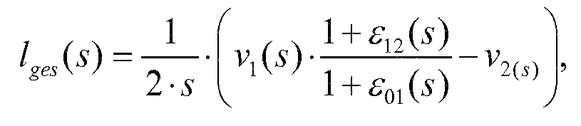
v1 étant la vitesse périphérique du point de serrage amont (102), v2 étant la vitesse périphérique du point de serrage aval (103), ε01 étant l'étirement de la bande de matériau (101) entre le point de serrage amont (102) et la danseuse (110) et ε12 étant l'étirement de la bande de matériau (101) entre la danseuse (110) et le point de serrage aval (103). - Unité de calcul (150), prévue pour mettre en oeuvre un procédé selon l'une quelconque des revendications précédentes.
Applications Claiming Priority (1)
| Application Number | Priority Date | Filing Date | Title |
|---|---|---|---|
| DE102010013782A DE102010013782A1 (de) | 2010-04-03 | 2010-04-03 | Verfahren zur Bestimmung wenigstens eines Reglerparameters eines Tänzerlage-Regelglieds |
Publications (3)
| Publication Number | Publication Date |
|---|---|
| EP2371748A2 EP2371748A2 (fr) | 2011-10-05 |
| EP2371748A3 EP2371748A3 (fr) | 2012-03-28 |
| EP2371748B1 true EP2371748B1 (fr) | 2014-12-31 |
Family
ID=44235378
Family Applications (1)
| Application Number | Title | Priority Date | Filing Date |
|---|---|---|---|
| EP11001033.7A Revoked EP2371748B1 (fr) | 2010-04-03 | 2011-02-09 | Procédé de détermination d'au moins un paramètre de régulation d'un élément de régulation d'une position de danseuse |
Country Status (3)
| Country | Link |
|---|---|
| US (1) | US20110246127A1 (fr) |
| EP (1) | EP2371748B1 (fr) |
| DE (1) | DE102010013782A1 (fr) |
Families Citing this family (14)
| Publication number | Priority date | Publication date | Assignee | Title |
|---|---|---|---|---|
| EP2559641B1 (fr) * | 2011-08-17 | 2016-06-15 | Seiko Epson Corporation | Dispositif de transport de supports, dispositif d'impression, et procédé de transport de supports |
| DE102011117358A1 (de) * | 2011-10-29 | 2013-05-02 | Robert Bosch Gmbh | Verfahren zum Berechnen des Ausgangsdurchmessers einer Warenbahnwicklung auf einer Rolle nach einem Rollenwechsel |
| DE102011122520A1 (de) | 2011-12-29 | 2013-07-04 | Robert Bosch Gmbh | Verfahren zum Rüsten einer Materialbahnbearbeitungsmaschine, Vorrichtung zum Bearbeiten einer Materialbahn mit einer Materialbahnbearbeitungsmaschine, Anordnung aus einer Vorrichtung zum Bearbeiten einer Materialbahn mit einer Materialbahnbearbeitungsmaschine und aus einer digitalen Druckstufenvorrichtung und Verwendung einer elektronischen Datenschnittstelleneinrichtung |
| DE102012013435A1 (de) * | 2012-04-04 | 2013-10-10 | Robert Bosch Gmbh | Verfahren zur Vorregistrierung einerBearbeitungsstation |
| JP5894841B2 (ja) * | 2012-04-09 | 2016-03-30 | 株式会社日立産機システム | 巻出ロールの制御装置及びその制御方法 |
| DE112014005964B4 (de) | 2013-12-17 | 2020-07-09 | Mitsubishi Electric Corporation | Vorrichtung zum Steuern eines Transports zwischen Walzen |
| JP6510914B2 (ja) * | 2015-07-02 | 2019-05-08 | 株式会社タカゾノテクノロジー | 薬剤包装装置 |
| JP6691879B2 (ja) * | 2017-02-28 | 2020-05-13 | 株式会社沖データ | 媒体供給装置 |
| EP3392029B1 (fr) * | 2017-04-21 | 2022-01-05 | Held Technologie GmbH | Dispositif d'alimentation pour une presse à double bande, système de presse à double bande et procédé de fonctionnement |
| MX2021008547A (es) | 2019-01-31 | 2021-08-19 | Kimberly Clark Co | Control de tension de trama mejorado. |
| US11801696B2 (en) * | 2019-12-16 | 2023-10-31 | Brother Kogyo Kabushiki Kaisha | Sheet conveyor and image forming system |
| JP7451191B2 (ja) | 2020-01-28 | 2024-03-18 | 住友重機械工業株式会社 | 制御装置およびロール・ツー・ロール搬送システム |
| JP2022085082A (ja) * | 2020-11-27 | 2022-06-08 | ブラザー工業株式会社 | 搬送装置および画像記録装置 |
| DE102021120371A1 (de) * | 2021-08-05 | 2023-02-09 | Multivac Sepp Haggenmüller Se & Co. Kg | Verpackungsmaschine mit folientransporteinrichtung sowie verfahren |
Family Cites Families (15)
| Publication number | Priority date | Publication date | Assignee | Title |
|---|---|---|---|---|
| US3006571A (en) * | 1958-06-23 | 1961-10-31 | Miehle Goss Dexter Inc | Web tensioning system |
| CA961570A (en) * | 1969-11-27 | 1975-01-21 | Lucio Stabile | Systems for driving reels at controlled speed and power and improved apparatus for effecting such driving |
| DE2225614C3 (de) * | 1972-05-26 | 1983-04-14 | P.I.V. Antrieb Werner Reimers GmbH & Co KG, 6380 Bad Homburg | Einrichtung zur Regelung der Zugkraft bei Wickeleinrichtungen |
| DE2915042A1 (de) | 1979-04-12 | 1980-10-23 | Gizeh Werk Gmbh | Vorrichtung zum rollen von zigaretten |
| DE8615787U1 (de) * | 1986-06-12 | 1986-08-07 | Wolff Walsrode Ag, 3030 Walsrode | Abrollvorrichtung |
| DE3734433A1 (de) * | 1987-10-12 | 1989-04-20 | Sucker & Franz Mueller Gmbh | Verfahren zum steuern der wickelspannung einer fadenschar beim bilden eines wickels |
| DE19501982B4 (de) * | 1995-01-24 | 2009-06-10 | Elau Gmbh | Zuführvorrichtung einer diskontinuierlich bahnförmiges Material verarbeitenden Maschine |
| DE19520955C2 (de) * | 1995-06-08 | 1999-10-28 | Roland Man Druckmasch | Regelanordnung für Abwickeleinrichtungen für Bahnen |
| DE19824798A1 (de) * | 1998-06-03 | 1999-12-09 | Indag Gmbh & Co Betriebs Kg | Vorrichtung und Verfahren zum Zuführen von Folien |
| DE102005008223A1 (de) * | 2005-02-22 | 2006-08-31 | Man Roland Druckmaschinen Ag | Rollenwechsler einer Rollendruckmaschine sowie Verfahren zur Regelung eines Rollenwechslers |
| DE102005056802A1 (de) | 2005-11-29 | 2007-05-31 | Bosch Rexroth Ag | Regelung der Bahnspannung einer Warenbahn |
| US7774085B2 (en) * | 2007-05-18 | 2010-08-10 | Xerox Corporation | Inertia compensating dancer roll for web feed |
| DE102007049680A1 (de) * | 2007-10-17 | 2009-04-23 | Robert Bosch Gmbh | Verfahren zum Berechnen des Durchmessers einer Warenbahnwicklung auf einer Rolle sowie Wickelsteuerungssystem |
| DE102008035639A1 (de) | 2008-07-31 | 2010-02-04 | Robert Bosch Gmbh | Verfahren zur Modellierung eines Regelkreises für eine Bearbeitungsmaschine |
| DE102009019624A1 (de) | 2009-04-30 | 2010-11-04 | Robert Bosch Gmbh | Verfahren zur Bestimmung wenigstens eines Reglerparameters eines Regelglieds in einem Bahnspannungs-Regelkreis für eine Bearbeitungsmaschine |
-
2010
- 2010-04-03 DE DE102010013782A patent/DE102010013782A1/de not_active Withdrawn
-
2011
- 2011-02-09 EP EP11001033.7A patent/EP2371748B1/fr not_active Revoked
- 2011-03-29 US US13/075,074 patent/US20110246127A1/en not_active Abandoned
Also Published As
| Publication number | Publication date |
|---|---|
| DE102010013782A1 (de) | 2011-10-06 |
| EP2371748A2 (fr) | 2011-10-05 |
| US20110246127A1 (en) | 2011-10-06 |
| EP2371748A3 (fr) | 2012-03-28 |
Similar Documents
| Publication | Publication Date | Title |
|---|---|---|
| EP2371748B1 (fr) | Procédé de détermination d'au moins un paramètre de régulation d'un élément de régulation d'une position de danseuse | |
| EP2386511B1 (fr) | Contrôle de tension d'une bande en mouvement | |
| DE10335887B4 (de) | Verfahren und Vorrichtung zum Regeln eines Schnittregisterfehlers und einer Bahnzugkraft einer Rollenrotationsdruckmaschine | |
| EP0976674B2 (fr) | Dispositif de réglage de la tension d'une bande | |
| DE2248364C2 (de) | Verfahren und Vorrichtung zur Korrektur des Bildstands in einer bahnförmiges Material bearbeitenden Maschine | |
| EP1795470B1 (fr) | Procédé pour déterminer la tension d'une bande de matière | |
| DE10335888B4 (de) | Verfahren und Vorrichtung zum Regeln des Gesamt-Schnittregisterfehlers einer Rollenrotationsdruckmaschine | |
| EP1505025B1 (fr) | Méthode et dispositif pour contrôler la tension d'une bande et le répérage de coup d'une imprimante rotative | |
| EP2246760B1 (fr) | Procédé de détermination d'au moins un paramètre de réglage d'une articulation de réglage dans un circuit de réglage de tension de bande pour une machine de traitement | |
| DE102009016206A1 (de) | Verfahren zur Bahnspannungseinstellung | |
| EP2349721A2 (fr) | Procédé de correction automatique de l'axe sur une machine de traitement destinée à traiter un produit en bande | |
| EP2524806B2 (fr) | Procédé de réglage de la tension de bande dans une machine de traitement de bande | |
| EP2067725B1 (fr) | Procédé de correction d'axe dans une machine de traitement et machine de traitement | |
| DE102007037564B4 (de) | Verfahren zur Achskorrektur bei einer Verarbeitungsmaschine | |
| EP0534151B1 (fr) | Procédé et installation pour réguler la force de traction d'une matière textile en bande | |
| EP3988485B1 (fr) | Paramétrage d'un régulateur de force de traction | |
| AT511029A2 (de) | Verfahren zur regelung der bahnspannung in einem einen tänzer aufweisenden bahnspannungsabschnitt | |
| DE102010050821A1 (de) | Verfahren zur Regelung der Bahnspannung in einem einen Tänzer aufweisenden ersten Bahnspannungsabschnitt | |
| DE102012017575A1 (de) | Verfahren zum Regeln eines Bearbeitungsregisters in einer Bahnbearbeitungsmaschine mit variabler Klemmung | |
| DE102013214731A1 (de) | Computerimplementiertes Verfahren zur Bahnzugkrafteinstellung |
Legal Events
| Date | Code | Title | Description |
|---|---|---|---|
| PUAI | Public reference made under article 153(3) epc to a published international application that has entered the european phase |
Free format text: ORIGINAL CODE: 0009012 |
|
| AK | Designated contracting states |
Kind code of ref document: A2 Designated state(s): AL AT BE BG CH CY CZ DE DK EE ES FI FR GB GR HR HU IE IS IT LI LT LU LV MC MK MT NL NO PL PT RO RS SE SI SK SM TR |
|
| AX | Request for extension of the european patent |
Extension state: BA ME |
|
| PUAL | Search report despatched |
Free format text: ORIGINAL CODE: 0009013 |
|
| AK | Designated contracting states |
Kind code of ref document: A3 Designated state(s): AL AT BE BG CH CY CZ DE DK EE ES FI FR GB GR HR HU IE IS IT LI LT LU LV MC MK MT NL NO PL PT RO RS SE SI SK SM TR |
|
| AX | Request for extension of the european patent |
Extension state: BA ME |
|
| RIC1 | Information provided on ipc code assigned before grant |
Ipc: B65H 23/188 20060101AFI20120223BHEP |
|
| 17P | Request for examination filed |
Effective date: 20120928 |
|
| REG | Reference to a national code |
Ref country code: DE Ref legal event code: R079 Ref document number: 502011005431 Country of ref document: DE Free format text: PREVIOUS MAIN CLASS: B65H0023188000 Ipc: B65H0023182000 |
|
| GRAP | Despatch of communication of intention to grant a patent |
Free format text: ORIGINAL CODE: EPIDOSNIGR1 |
|
| RIC1 | Information provided on ipc code assigned before grant |
Ipc: B65H 23/182 20060101AFI20140828BHEP Ipc: B65H 23/185 20060101ALI20140828BHEP Ipc: B65H 23/192 20060101ALI20140828BHEP Ipc: B65H 23/188 20060101ALI20140828BHEP |
|
| INTG | Intention to grant announced |
Effective date: 20140918 |
|
| GRAS | Grant fee paid |
Free format text: ORIGINAL CODE: EPIDOSNIGR3 |
|
| GRAA | (expected) grant |
Free format text: ORIGINAL CODE: 0009210 |
|
| STAA | Information on the status of an ep patent application or granted ep patent |
Free format text: STATUS: THE PATENT HAS BEEN GRANTED |
|
| AK | Designated contracting states |
Kind code of ref document: B1 Designated state(s): AL AT BE BG CH CY CZ DE DK EE ES FI FR GB GR HR HU IE IS IT LI LT LU LV MC MK MT NL NO PL PT RO RS SE SI SK SM TR |
|
| REG | Reference to a national code |
Ref country code: CH Ref legal event code: EP Ref country code: GB Ref legal event code: FG4D Free format text: NOT ENGLISH |
|
| REG | Reference to a national code |
Ref country code: IE Ref legal event code: FG4D Free format text: LANGUAGE OF EP DOCUMENT: GERMAN |
|
| REG | Reference to a national code |
Ref country code: AT Ref legal event code: REF Ref document number: 704256 Country of ref document: AT Kind code of ref document: T Effective date: 20150215 |
|
| REG | Reference to a national code |
Ref country code: DE Ref legal event code: R096 Ref document number: 502011005431 Country of ref document: DE Effective date: 20150219 |
|
| PG25 | Lapsed in a contracting state [announced via postgrant information from national office to epo] |
Ref country code: NO Free format text: LAPSE BECAUSE OF FAILURE TO SUBMIT A TRANSLATION OF THE DESCRIPTION OR TO PAY THE FEE WITHIN THE PRESCRIBED TIME-LIMIT Effective date: 20150331 Ref country code: FI Free format text: LAPSE BECAUSE OF FAILURE TO SUBMIT A TRANSLATION OF THE DESCRIPTION OR TO PAY THE FEE WITHIN THE PRESCRIBED TIME-LIMIT Effective date: 20141231 Ref country code: LT Free format text: LAPSE BECAUSE OF FAILURE TO SUBMIT A TRANSLATION OF THE DESCRIPTION OR TO PAY THE FEE WITHIN THE PRESCRIBED TIME-LIMIT Effective date: 20141231 |
|
| REG | Reference to a national code |
Ref country code: NL Ref legal event code: VDEP Effective date: 20141231 |
|
| REG | Reference to a national code |
Ref country code: LT Ref legal event code: MG4D |
|
| PG25 | Lapsed in a contracting state [announced via postgrant information from national office to epo] |
Ref country code: HR Free format text: LAPSE BECAUSE OF FAILURE TO SUBMIT A TRANSLATION OF THE DESCRIPTION OR TO PAY THE FEE WITHIN THE PRESCRIBED TIME-LIMIT Effective date: 20141231 Ref country code: LV Free format text: LAPSE BECAUSE OF FAILURE TO SUBMIT A TRANSLATION OF THE DESCRIPTION OR TO PAY THE FEE WITHIN THE PRESCRIBED TIME-LIMIT Effective date: 20141231 Ref country code: SE Free format text: LAPSE BECAUSE OF FAILURE TO SUBMIT A TRANSLATION OF THE DESCRIPTION OR TO PAY THE FEE WITHIN THE PRESCRIBED TIME-LIMIT Effective date: 20141231 Ref country code: GR Free format text: LAPSE BECAUSE OF FAILURE TO SUBMIT A TRANSLATION OF THE DESCRIPTION OR TO PAY THE FEE WITHIN THE PRESCRIBED TIME-LIMIT Effective date: 20150401 Ref country code: RS Free format text: LAPSE BECAUSE OF FAILURE TO SUBMIT A TRANSLATION OF THE DESCRIPTION OR TO PAY THE FEE WITHIN THE PRESCRIBED TIME-LIMIT Effective date: 20141231 |
|
| PG25 | Lapsed in a contracting state [announced via postgrant information from national office to epo] |
Ref country code: NL Free format text: LAPSE BECAUSE OF FAILURE TO SUBMIT A TRANSLATION OF THE DESCRIPTION OR TO PAY THE FEE WITHIN THE PRESCRIBED TIME-LIMIT Effective date: 20141231 |
|
| PG25 | Lapsed in a contracting state [announced via postgrant information from national office to epo] |
Ref country code: SK Free format text: LAPSE BECAUSE OF FAILURE TO SUBMIT A TRANSLATION OF THE DESCRIPTION OR TO PAY THE FEE WITHIN THE PRESCRIBED TIME-LIMIT Effective date: 20141231 Ref country code: CZ Free format text: LAPSE BECAUSE OF FAILURE TO SUBMIT A TRANSLATION OF THE DESCRIPTION OR TO PAY THE FEE WITHIN THE PRESCRIBED TIME-LIMIT Effective date: 20141231 Ref country code: ES Free format text: LAPSE BECAUSE OF FAILURE TO SUBMIT A TRANSLATION OF THE DESCRIPTION OR TO PAY THE FEE WITHIN THE PRESCRIBED TIME-LIMIT Effective date: 20141231 Ref country code: RO Free format text: LAPSE BECAUSE OF FAILURE TO SUBMIT A TRANSLATION OF THE DESCRIPTION OR TO PAY THE FEE WITHIN THE PRESCRIBED TIME-LIMIT Effective date: 20141231 |
|
| PG25 | Lapsed in a contracting state [announced via postgrant information from national office to epo] |
Ref country code: IS Free format text: LAPSE BECAUSE OF FAILURE TO SUBMIT A TRANSLATION OF THE DESCRIPTION OR TO PAY THE FEE WITHIN THE PRESCRIBED TIME-LIMIT Effective date: 20150430 Ref country code: PL Free format text: LAPSE BECAUSE OF FAILURE TO SUBMIT A TRANSLATION OF THE DESCRIPTION OR TO PAY THE FEE WITHIN THE PRESCRIBED TIME-LIMIT Effective date: 20141231 |
|
| PG25 | Lapsed in a contracting state [announced via postgrant information from national office to epo] |
Ref country code: LU Free format text: LAPSE BECAUSE OF FAILURE TO SUBMIT A TRANSLATION OF THE DESCRIPTION OR TO PAY THE FEE WITHIN THE PRESCRIBED TIME-LIMIT Effective date: 20150209 |
|
| REG | Reference to a national code |
Ref country code: CH Ref legal event code: PL Ref country code: DE Ref legal event code: R026 Ref document number: 502011005431 Country of ref document: DE |
|
| PLBI | Opposition filed |
Free format text: ORIGINAL CODE: 0009260 |
|
| PG25 | Lapsed in a contracting state [announced via postgrant information from national office to epo] |
Ref country code: MC Free format text: LAPSE BECAUSE OF FAILURE TO SUBMIT A TRANSLATION OF THE DESCRIPTION OR TO PAY THE FEE WITHIN THE PRESCRIBED TIME-LIMIT Effective date: 20141231 Ref country code: EE Free format text: LAPSE BECAUSE OF FAILURE TO SUBMIT A TRANSLATION OF THE DESCRIPTION OR TO PAY THE FEE WITHIN THE PRESCRIBED TIME-LIMIT Effective date: 20141231 Ref country code: CH Free format text: LAPSE BECAUSE OF NON-PAYMENT OF DUE FEES Effective date: 20150228 Ref country code: LI Free format text: LAPSE BECAUSE OF NON-PAYMENT OF DUE FEES Effective date: 20150228 Ref country code: DK Free format text: LAPSE BECAUSE OF FAILURE TO SUBMIT A TRANSLATION OF THE DESCRIPTION OR TO PAY THE FEE WITHIN THE PRESCRIBED TIME-LIMIT Effective date: 20141231 |
|
| 26 | Opposition filed |
Opponent name: SIEMENS AKTIENGESELLSCHAFT Effective date: 20150930 |
|
| REG | Reference to a national code |
Ref country code: IE Ref legal event code: MM4A |
|
| PLAX | Notice of opposition and request to file observation + time limit sent |
Free format text: ORIGINAL CODE: EPIDOSNOBS2 |
|
| REG | Reference to a national code |
Ref country code: FR Ref legal event code: ST Effective date: 20151030 |
|
| PG25 | Lapsed in a contracting state [announced via postgrant information from national office to epo] |
Ref country code: IT Free format text: LAPSE BECAUSE OF FAILURE TO SUBMIT A TRANSLATION OF THE DESCRIPTION OR TO PAY THE FEE WITHIN THE PRESCRIBED TIME-LIMIT Effective date: 20141231 |
|
| PG25 | Lapsed in a contracting state [announced via postgrant information from national office to epo] |
Ref country code: IE Free format text: LAPSE BECAUSE OF NON-PAYMENT OF DUE FEES Effective date: 20150209 |
|
| PG25 | Lapsed in a contracting state [announced via postgrant information from national office to epo] |
Ref country code: FR Free format text: LAPSE BECAUSE OF NON-PAYMENT OF DUE FEES Effective date: 20150302 Ref country code: SI Free format text: LAPSE BECAUSE OF FAILURE TO SUBMIT A TRANSLATION OF THE DESCRIPTION OR TO PAY THE FEE WITHIN THE PRESCRIBED TIME-LIMIT Effective date: 20141231 |
|
| PLBB | Reply of patent proprietor to notice(s) of opposition received |
Free format text: ORIGINAL CODE: EPIDOSNOBS3 |
|
| PG25 | Lapsed in a contracting state [announced via postgrant information from national office to epo] |
Ref country code: MT Free format text: LAPSE BECAUSE OF FAILURE TO SUBMIT A TRANSLATION OF THE DESCRIPTION OR TO PAY THE FEE WITHIN THE PRESCRIBED TIME-LIMIT Effective date: 20141231 |
|
| PG25 | Lapsed in a contracting state [announced via postgrant information from national office to epo] |
Ref country code: BG Free format text: LAPSE BECAUSE OF FAILURE TO SUBMIT A TRANSLATION OF THE DESCRIPTION OR TO PAY THE FEE WITHIN THE PRESCRIBED TIME-LIMIT Effective date: 20141231 Ref country code: HU Free format text: LAPSE BECAUSE OF FAILURE TO SUBMIT A TRANSLATION OF THE DESCRIPTION OR TO PAY THE FEE WITHIN THE PRESCRIBED TIME-LIMIT; INVALID AB INITIO Effective date: 20110209 Ref country code: SM Free format text: LAPSE BECAUSE OF FAILURE TO SUBMIT A TRANSLATION OF THE DESCRIPTION OR TO PAY THE FEE WITHIN THE PRESCRIBED TIME-LIMIT Effective date: 20141231 |
|
| PGFP | Annual fee paid to national office [announced via postgrant information from national office to epo] |
Ref country code: GB Payment date: 20170221 Year of fee payment: 7 Ref country code: AT Payment date: 20170217 Year of fee payment: 7 |
|
| PG25 | Lapsed in a contracting state [announced via postgrant information from national office to epo] |
Ref country code: CY Free format text: LAPSE BECAUSE OF FAILURE TO SUBMIT A TRANSLATION OF THE DESCRIPTION OR TO PAY THE FEE WITHIN THE PRESCRIBED TIME-LIMIT Effective date: 20141231 |
|
| PG25 | Lapsed in a contracting state [announced via postgrant information from national office to epo] |
Ref country code: BE Free format text: LAPSE BECAUSE OF NON-PAYMENT OF DUE FEES Effective date: 20150228 Ref country code: PT Free format text: LAPSE BECAUSE OF FAILURE TO SUBMIT A TRANSLATION OF THE DESCRIPTION OR TO PAY THE FEE WITHIN THE PRESCRIBED TIME-LIMIT Effective date: 20150501 |
|
| PG25 | Lapsed in a contracting state [announced via postgrant information from national office to epo] |
Ref country code: TR Free format text: LAPSE BECAUSE OF FAILURE TO SUBMIT A TRANSLATION OF THE DESCRIPTION OR TO PAY THE FEE WITHIN THE PRESCRIBED TIME-LIMIT Effective date: 20141231 |
|
| PLAB | Opposition data, opponent's data or that of the opponent's representative modified |
Free format text: ORIGINAL CODE: 0009299OPPO |
|
| R26 | Opposition filed (corrected) |
Opponent name: SIEMENS AKTIENGESELLSCHAFT Effective date: 20150930 |
|
| RDAF | Communication despatched that patent is revoked |
Free format text: ORIGINAL CODE: EPIDOSNREV1 |
|
| STAA | Information on the status of an ep patent application or granted ep patent |
Free format text: STATUS: THE PATENT HAS BEEN GRANTED |
|
| APAH | Appeal reference modified |
Free format text: ORIGINAL CODE: EPIDOSCREFNO |
|
| APBM | Appeal reference recorded |
Free format text: ORIGINAL CODE: EPIDOSNREFNO |
|
| APBP | Date of receipt of notice of appeal recorded |
Free format text: ORIGINAL CODE: EPIDOSNNOA2O |
|
| PG25 | Lapsed in a contracting state [announced via postgrant information from national office to epo] |
Ref country code: MK Free format text: LAPSE BECAUSE OF FAILURE TO SUBMIT A TRANSLATION OF THE DESCRIPTION OR TO PAY THE FEE WITHIN THE PRESCRIBED TIME-LIMIT Effective date: 20141231 |
|
| APBQ | Date of receipt of statement of grounds of appeal recorded |
Free format text: ORIGINAL CODE: EPIDOSNNOA3O |
|
| REG | Reference to a national code |
Ref country code: AT Ref legal event code: MM01 Ref document number: 704256 Country of ref document: AT Kind code of ref document: T Effective date: 20180209 |
|
| GBPC | Gb: european patent ceased through non-payment of renewal fee |
Effective date: 20180209 |
|
| PG25 | Lapsed in a contracting state [announced via postgrant information from national office to epo] |
Ref country code: AL Free format text: LAPSE BECAUSE OF FAILURE TO SUBMIT A TRANSLATION OF THE DESCRIPTION OR TO PAY THE FEE WITHIN THE PRESCRIBED TIME-LIMIT Effective date: 20141231 |
|
| PG25 | Lapsed in a contracting state [announced via postgrant information from national office to epo] |
Ref country code: AT Free format text: LAPSE BECAUSE OF NON-PAYMENT OF DUE FEES Effective date: 20180209 |
|
| PG25 | Lapsed in a contracting state [announced via postgrant information from national office to epo] |
Ref country code: GB Free format text: LAPSE BECAUSE OF NON-PAYMENT OF DUE FEES Effective date: 20180209 |
|
| RAP2 | Party data changed (patent owner data changed or rights of a patent transferred) |
Owner name: ROBERT BOSCH GMBH |
|
| PGFP | Annual fee paid to national office [announced via postgrant information from national office to epo] |
Ref country code: DE Payment date: 20210420 Year of fee payment: 11 |
|
| REG | Reference to a national code |
Ref country code: DE Ref legal event code: R103 Ref document number: 502011005431 Country of ref document: DE Ref country code: DE Ref legal event code: R064 Ref document number: 502011005431 Country of ref document: DE |
|
| APBU | Appeal procedure closed |
Free format text: ORIGINAL CODE: EPIDOSNNOA9O |
|
| RDAG | Patent revoked |
Free format text: ORIGINAL CODE: 0009271 |
|
| STAA | Information on the status of an ep patent application or granted ep patent |
Free format text: STATUS: PATENT REVOKED |
|
| REG | Reference to a national code |
Ref country code: FI Ref legal event code: MGE |
|
| 27W | Patent revoked |
Effective date: 20220221 |
|
| REG | Reference to a national code |
Ref country code: AT Ref legal event code: MA03 Ref document number: 704256 Country of ref document: AT Kind code of ref document: T Effective date: 20220221 |