EP2369099B1 - Rosette de porte - Google Patents
Rosette de porte Download PDFInfo
- Publication number
- EP2369099B1 EP2369099B1 EP11001670.6A EP11001670A EP2369099B1 EP 2369099 B1 EP2369099 B1 EP 2369099B1 EP 11001670 A EP11001670 A EP 11001670A EP 2369099 B1 EP2369099 B1 EP 2369099B1
- Authority
- EP
- European Patent Office
- Prior art keywords
- handle
- actuating element
- door
- guide plate
- locking
- Prior art date
- Legal status (The legal status is an assumption and is not a legal conclusion. Google has not performed a legal analysis and makes no representation as to the accuracy of the status listed.)
- Active
Links
- 230000004308 accommodation Effects 0.000 claims 1
- 238000006073 displacement reaction Methods 0.000 description 2
- 230000003993 interaction Effects 0.000 description 2
- 238000009434 installation Methods 0.000 description 1
- 230000002093 peripheral effect Effects 0.000 description 1
- 230000001960 triggered effect Effects 0.000 description 1
Images


Classifications
-
- E—FIXED CONSTRUCTIONS
- E05—LOCKS; KEYS; WINDOW OR DOOR FITTINGS; SAFES
- E05B—LOCKS; ACCESSORIES THEREFOR; HANDCUFFS
- E05B3/00—Fastening knobs or handles to lock or latch parts
- E05B3/06—Fastening knobs or handles to lock or latch parts by means arranged in or on the rose or escutcheon
Definitions
- the invention relates to a device for detachable, axial fixing of a bearing portion of a handle with the features of the preamble of claim 1.
- Such a device is from the document DE 103 11 546 A1 known and used to connect a door handle or a window handle to a door.
- the handle in question has a bearing portion with a circumferential groove and a bearing unit which is connected door-tight and comprises a bolt slide having two arms and engages for axially fixing the handle with its two arms in the circumferential groove of the bearing portion of the handle.
- the latch slide is radially displaceable between a release position and a latch position. This can be done by means of a special tool or in a manual manner.
- the bolt slide is behind a cover or panel, which must be released before operation.
- the bearing section has a plurality of grooves and the bearing unit comprises a latch slide designed as a spring element.
- the latch slide is adjustable between a latch position and a release position.
- the bolt slide engages the axial location of the bearing portion of the handle in one of the grooves.
- the bearing unit comprises an actuating element by means of which the bolt slide is axially displaceable.
- the GB 371,573 discloses a device for releasable, axial fixing of a bearing portion of a door knob on a bearing unit of a door.
- the doorknob can be fixed in the grooves of a spindle by means of a locking slide.
- the bolt slide is radially displaceable between a latch position and a release position.
- the Bearing unit also includes an actuating element by means of which the bolt slide is radially displaceable.
- the invention has for its object to provide a device of the type mentioned in the introduction with a simply actuated latch slide.
- an apparatus for the detachable, axial fixing of a bearing portion of a handle in particular a door handle, a window handle or the like, proposed on a storage unit of a door or a window, wherein the bearing portion of the handle has a circumferential groove and the bearing unit comprises at least one latch slide, which is radially displaceable between a latch position and a release position and engages the axial direction of the bearing portion of the handle in the circumferential groove.
- the bearing unit comprises an actuating element, by means of which the bolt slide is radially displaceable.
- the essence of the invention is therefore that the device itself comprises an actuator for the bolt slide. It can therefore be dispensed with an additional tool for actuating the bolt slide.
- the locking slide in the device according to the invention comprises a control link, in which engages a control pin of the actuating element.
- An offset of the actuating element or a rotation of the actuating element thus leads to a displacement of the locking slide in the radial direction relative to the axis of the bearing portion of the handle, whereby it is released or secured.
- a particularly easy to handle device is when the actuator is a cover plate of the bearing unit, which is penetrated by the bearing portion of the handle and on the inside of which at least one control pin is arranged.
- the cover plate forms the visible surface of the bearing unit and is usually to grasp manually without problems.
- the actuating element is actuated by a rotation about the axis of the bearing portion.
- the device according to the invention preferably has a guide plate for the at least one locking slide.
- a guide plate for the at least one locking slide.
- webs are formed or formed on the guide plate, which limit the bolt slide laterally and deform the guide jaws.
- a holding plate is preferably provided, which is arranged between the actuating element and the guide plate for the bolt slide.
- the holding plate or the guide plate has at least one locking element on which the actuating element is locked in the locking position of the locking slide.
- the actuating element in particular the cover plate designed as an actuating element, has at least one latching pin which cooperates with the latching element.
- the holding plate expediently includes screw receptacles. These may be formed like a bush and engage through corresponding holes in the guide plate, so that the holding plate and the guide plate have a clear rotational position to each other.
- cover plate or other elements of the device can be actuated only by means of an additional tool, which respect offers theft protection advantages.
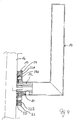
- a device 10 for releasably, axially fixing a shaft-like bearing portion 12 of a door handle 14 is shown.
- the door handle 14 can be detached from a door leaf 16 without tools or connected thereto.
- the device 10 forms a bearing unit, which has a guide sleeve 18, which is penetrated by the bearing portion 12 of the door handle 14 in its installed position.
- a guide plate 20 is attached in a coaxial manner, which serves for the radial guidance of two transom sliders 22A and 22B, based on the bearing portion 12 are displaceable in the radial direction between a latch position and a release position.
- Adjoining the guide plate 20 in the axial direction of the bearing section 12 is a retaining plate 24, by means of which the device 10 can be fixed to the door leaf 16.
- the holding plate 24 is in turn overlapped by a cover or aperture 26.
- the cover 26 is annular and has at its periphery an annular collar. On its inside, two control pins 28 A and 28 B are formed on the cover 26, which extend parallel to the axis of the bearing portion 12 of the door handle 14. Furthermore, two mushroom-shaped latching pins 30A and 30B are formed on the inside of the cover 26. A central circular recess 32 of the cover 26 is penetrated by the bearing portion 12 of the door handle 14.
- the retaining plate 24 is also annular and has for connection to the door leaf 16 has two receiving bushes or sleeves 34 A and 34 B, can be plugged through the screws, which are bolted to the door leaf 14. Furthermore, the holding plate 24 has an annular collar 36 against which, in the installation position, the peripheral edge of the guide plate 20 rests, so that the guide plate 20 is overlapped by the holding plate 24. In addition to a central recess 38 for the passage of the bearing portion 12 of the door handle 14, the holding plate 24 has two arcuate recesses 40 A and 40 B, which are respectively penetrated by one of the control pins 28 A and 28 B of the cover 26.
- two further recesses 42A and 42B are arranged, which serve for locking the mushroom-shaped latching pins 30A and 30B of the cover 26 and are provided for this purpose with a radially widened portion 44, the in the circumferential direction via a constriction 46 merges into a latching portion 48, in which the latching pins 30A and 30B are arranged in the latch position of the bolt slide 22A and 22B.
- the locking portions 28 are each surrounded by a resilient web 50, so that the bottlenecks 46 can be overcome with a rotation of the cover 26 relative to the holding plate 24 of the locking pin 30A and 30B.
- the guide plate 20 also has a central recess 52 which is penetrated by the bearing portion 12 of the door handle 14. Furthermore, the guide plate 20 has two holes 54A and 54B penetrated by one of the sleeve-shaped screw receptacles 34A and 34B, respectively. In alignment with the arcuate recesses 40A and 40B, arcuate recesses 57A and 57B are also formed on the guide plate 20, in each of which one of the control pins 28A and 28B is guided.
- the guide plate 20 On the side facing away from the door leaf 16, the guide plate 20 has two webs 56A and 56B which laterally delimit the locking slides 22A and 22B and thus guide them in the radial direction.
- the locking slide 22A and 22B each have a circular end face 58A and 58B, which engages in the locking position of the bolt slide 22A and 22B in a arranged on the circumference of the bearing portion of the door handle 14 annular groove 60.
- the locking slides 22A and 22B each have a slot 62A or 62B in the form of a control cam, whose axis is inclined relative to the radial direction and which is also penetrated by one of the control pins 28A and 28B.
- the orientation of the control slots 62A and 62B can be triggered by rotation of the cover plate 26 via the control pins 28A and 28B, a radial displacement of the spool 22A and 22B.
- the determination of the door handle 14 from the device 10 takes place in the manner described below.
- the unit which consists of the guide sleeve 18 of the guide plate 20, the latch slides 22 A and 22 B and the holding plate 24, screwed to the door leaf 16. It should be ensured here that the locking slides 22A and 22B are each in their release position, in which they lie outside the central recess 52, but between the webs 56A and 56B.
- the cover 26 is placed so that the control pins 28A and 28B via the recesses 40A and 40B in the slots 62A and 62B of the bolt slide 22A and 22B intervention.
- the bearing portion 12 of the door handle 14 can be inserted through the central recesses 32, 38, 52 in the device 10 and coupled with a door lock mechanism.
- the cover 26 is rotated in the clockwise direction until the latching pins 30A and 30B are latched in the latching portion 48 of the recesses 42A and 42B, that is, the cover 26 is rotated clockwise to the stop.
- the bolt slide 22A and 22B moved from their respective release position radially inwardly into its locked position in which it into the annular groove 60 of the bearing portion 12 of the door handle 14th intervention.
- the door handle 14 is connected captively to the door lock mechanism.
- the dismantling of the door handle 14 takes place in accordance with the reverse manner.
Landscapes
- Engineering & Computer Science (AREA)
- Mechanical Engineering (AREA)
- Hinges (AREA)
- Lock And Its Accessories (AREA)
- Patch Boards (AREA)
Claims (8)
- Dispositif pour la fixation détachable et axiale d'une zone de palier (12) d'une poignée (14), en particulier d'une poignée de porte, d'une poignée de fenêtre, d'une poignée de meuble ou d'autres choses semblables, à une unité de palier d'une porte ou d'une fenêtre, ladite zone de palier (12) de la poignée (14) comprenant une rainure circonférentielle (60) et ladite unité de palier comprenant au moins une glissière de verrouillage (22A, 22B), qui peut être déplacée radialement entre une position de verrouillage et une position de déverrouillage et s'engage dans la rainure circonférentielle (60) pour fixer axialement la zone de palier (12) de la poignée (14), ladite unité de palier comprenant un élément d'actuation (26), au moyen duquel la glissière de verrouillage (22A, 22B) peut être déplacée radialement, caractérisé en ce que la glissière de verrouillage (22A, 22B) comprend une coulisse de commande (62A, 62B), dans laquelle une goupille de commande (28A, 28B) de l'élément d'actuation (26) s'engage.
- Dispositif selon la revendication 1, caractérisé en ce que l'élément d'actuation est une plaque de recouvrement (26) de l'unité de palier, ladite plaque de recouvrement (26) étant pénétrée par la zone de palier (12) de la poignée (14) et étant disposée à son côté intérieur de la goupille de commande (28A, 28B).
- Dispositif selon l'une quelconque des revendications 1 à 2, caractérisé en ce que l'élément d'actuation (26) est actionné en été tourné autour d'un axe de la zone de palier (12).
- Dispositif selon l'une quelconque des revendications 1 à 3, caractérisé par une plaque de guidage (20) pour l'au moins une glissière de verrouillage (22A, 22B).
- Dispositif selon la revendication 4, caractérisé par une plaque de rétention (24) qui est disposée entre l'élément d'actuation (26) et la plaque de guidage (20) pour la glissière de verrouillage (22A, 22B).
- Dispositif selon la revendication 4 ou 5, caractérisé en ce qu'au moins un élément d'engagement, auquel l'élément d'actuation (26) s'engage dans la position de verrouillage de la glissière de verrouillage (22A, 22B), est réalisé à la plaque de guidage et/ou à la plaque de rétention.
- Dispositif selon la revendication 6, caractérisé en ce qu'au moins une goupille d'engagement (30A, 30B), qui interagit avec l'élément d'engagement, est réalisée à l'élément d'actuation (26).
- Dispositif selon l'une quelconque des revendications 4 à 7, caractérisé en ce qu'à la plaque de guidage et/ou à la plaque de rétention (24), des accommodations de vis (34A, 34B) sont réalisées pour relier l'unité de palier à la porte ou à la fenêtre.
Priority Applications (1)
| Application Number | Priority Date | Filing Date | Title |
|---|---|---|---|
| PL11001670T PL2369099T3 (pl) | 2010-03-23 | 2011-03-01 | Rozeta drzwiowa |
Applications Claiming Priority (1)
| Application Number | Priority Date | Filing Date | Title |
|---|---|---|---|
| DE201020004053 DE202010004053U1 (de) | 2010-03-23 | 2010-03-23 | Türrosette |
Publications (3)
| Publication Number | Publication Date |
|---|---|
| EP2369099A2 EP2369099A2 (fr) | 2011-09-28 |
| EP2369099A3 EP2369099A3 (fr) | 2015-04-15 |
| EP2369099B1 true EP2369099B1 (fr) | 2018-08-22 |
Family
ID=42243951
Family Applications (1)
| Application Number | Title | Priority Date | Filing Date |
|---|---|---|---|
| EP11001670.6A Active EP2369099B1 (fr) | 2010-03-23 | 2011-03-01 | Rosette de porte |
Country Status (3)
| Country | Link |
|---|---|
| EP (1) | EP2369099B1 (fr) |
| DE (2) | DE202010004053U1 (fr) |
| PL (1) | PL2369099T3 (fr) |
Families Citing this family (2)
| Publication number | Priority date | Publication date | Assignee | Title |
|---|---|---|---|---|
| CA3089770A1 (fr) * | 2018-07-12 | 2020-01-16 | Dormakaba Canada Inc. | Ensemble garniture pour une serrure de porte et procede d'assemblage d'une poignee de ce dernier |
| DE102021116534A1 (de) | 2021-06-25 | 2022-12-29 | WILKA Schließtechnik GmbH | Türbeschlag |
Family Cites Families (4)
| Publication number | Priority date | Publication date | Assignee | Title |
|---|---|---|---|---|
| GB371573A (en) * | 1931-03-31 | 1932-04-28 | Robert Benjamin Boden | Improvements in means for securing knobs, handles and the like to spindles |
| US2098868A (en) * | 1936-04-22 | 1937-11-09 | Grimmond Robert | Door handle and like fastening |
| DE10311546A1 (de) | 2003-03-17 | 2004-10-07 | Jado Ag | Vorrichtung zur lösbaren, axialen Festlegung einer Handhabe an einem Lagerteil, z. B. Türdrücker- oder Fenstergriffanordnung |
| ES2609261T3 (es) * | 2007-09-07 | 2017-04-19 | Dormakaba Deutschland Gmbh | Roseta con un dispositivo de seguridad |
-
2010
- 2010-03-23 DE DE201020004053 patent/DE202010004053U1/de not_active Expired - Lifetime
-
2011
- 2011-02-25 DE DE201110012469 patent/DE102011012469A1/de not_active Withdrawn
- 2011-03-01 EP EP11001670.6A patent/EP2369099B1/fr active Active
- 2011-03-01 PL PL11001670T patent/PL2369099T3/pl unknown
Non-Patent Citations (1)
| Title |
|---|
| None * |
Also Published As
| Publication number | Publication date |
|---|---|
| PL2369099T3 (pl) | 2018-12-31 |
| DE102011012469A1 (de) | 2011-12-15 |
| EP2369099A2 (fr) | 2011-09-28 |
| DE202010004053U1 (de) | 2010-06-10 |
| EP2369099A3 (fr) | 2015-04-15 |
Similar Documents
| Publication | Publication Date | Title |
|---|---|---|
| EP0918655B1 (fr) | Dispositif d'accouplement pour un vehicule | |
| DE102013202157B4 (de) | Kombinationsvorhängeschloss mit Scheibenform | |
| EP2796645B1 (fr) | Serrure à pêne dormant d'un meuble | |
| EP2906378B1 (fr) | Dispositif rapporté destiné à un système de perçage et système de perçage permettant de percer un élément d'assemblage | |
| EP2369099B1 (fr) | Rosette de porte | |
| DE3833758A1 (de) | Beschlag mit einer handhabe zur betaetigung der schlossnuss eines in eine tuer od. dgl. eingesetzten schlosses | |
| DE102013104874B3 (de) | Werkzeugrevolver | |
| EP1683938B1 (fr) | Pêne de verrouillage pour une crémone | |
| EP3498941B1 (fr) | Élément d'actionnement pourvu d'un dispositif de verrouillage | |
| DE10052495A1 (de) | Befestigungsvorrichtung | |
| DE202013011573U1 (de) | Drückergarnitur für Türen | |
| DE4041207C1 (en) | Furniture lock with slide bolt actuated by cylinder or key - has cylinder lock core with drive part angularly adjustable and arrestable in position | |
| EP3363969A1 (fr) | Poignée d'actionnement | |
| EP2243596A1 (fr) | Clé universelle | |
| DE102007039549A1 (de) | Verschlusseinrichtung und Tor, Tür oder dergleichen mit einer solchen Verschlusseinrichtung | |
| EP3626914B1 (fr) | Ferrure avec poignée et dispositif de rappel pour la poignée et procédé de transfert d'un dispositif de rappel entre une première position d'arrêt et une seconde position d'arrêt de la poignée | |
| DE102017110754A1 (de) | Werkzeugvorrichtung, insbesondere Fräswerkzeug | |
| EP0853991B1 (fr) | Tête de roulage radial | |
| EP2578891B1 (fr) | Adapteur | |
| EP0663498A1 (fr) | Serrure cylindrique | |
| DE102016123468B3 (de) | Schnell-dreh-antriebswerkzeug | |
| EP2031156A2 (fr) | Mécanisme de rappel pour une poignée de porte | |
| DE202019104119U1 (de) | Bedieneinheit, Schließsystem und Betätigungseinheit | |
| DE3210448A1 (de) | Schnellspannmutter | |
| DE3205133A1 (de) | Vorrichtung zur winkelverstellung der rueckenlehne eines sitzes, insbesondere kraftfahrzeugsitzes |
Legal Events
| Date | Code | Title | Description |
|---|---|---|---|
| PUAI | Public reference made under article 153(3) epc to a published international application that has entered the european phase |
Free format text: ORIGINAL CODE: 0009012 |
|
| AK | Designated contracting states |
Kind code of ref document: A2 Designated state(s): AL AT BE BG CH CY CZ DE DK EE ES FI FR GB GR HR HU IE IS IT LI LT LU LV MC MK MT NL NO PL PT RO RS SE SI SK SM TR |
|
| AX | Request for extension of the european patent |
Extension state: BA ME |
|
| PUAL | Search report despatched |
Free format text: ORIGINAL CODE: 0009013 |
|
| AK | Designated contracting states |
Kind code of ref document: A3 Designated state(s): AL AT BE BG CH CY CZ DE DK EE ES FI FR GB GR HR HU IE IS IT LI LT LU LV MC MK MT NL NO PL PT RO RS SE SI SK SM TR |
|
| AX | Request for extension of the european patent |
Extension state: BA ME |
|
| RIC1 | Information provided on ipc code assigned before grant |
Ipc: E05B 3/06 20060101AFI20150310BHEP |
|
| 17P | Request for examination filed |
Effective date: 20150629 |
|
| RAX | Requested extension states of the european patent have changed |
Extension state: BA Payment date: 20150629 Extension state: ME Payment date: 20150629 |
|
| RBV | Designated contracting states (corrected) |
Designated state(s): AL AT BE BG CH CY CZ DE DK EE ES FI FR GB GR HR HU IE IS IT LI LT LU LV MC MK MT NL NO PL PT RO RS SE SI SK SM TR |
|
| GRAP | Despatch of communication of intention to grant a patent |
Free format text: ORIGINAL CODE: EPIDOSNIGR1 |
|
| STAA | Information on the status of an ep patent application or granted ep patent |
Free format text: STATUS: GRANT OF PATENT IS INTENDED |
|
| INTG | Intention to grant announced |
Effective date: 20180319 |
|
| GRAS | Grant fee paid |
Free format text: ORIGINAL CODE: EPIDOSNIGR3 |
|
| GRAA | (expected) grant |
Free format text: ORIGINAL CODE: 0009210 |
|
| STAA | Information on the status of an ep patent application or granted ep patent |
Free format text: STATUS: THE PATENT HAS BEEN GRANTED |
|
| AK | Designated contracting states |
Kind code of ref document: B1 Designated state(s): AL AT BE BG CH CY CZ DE DK EE ES FI FR GB GR HR HU IE IS IT LI LT LU LV MC MK MT NL NO PL PT RO RS SE SI SK SM TR |
|
| AX | Request for extension of the european patent |
Extension state: BA ME |
|
| REG | Reference to a national code |
Ref country code: GB Ref legal event code: FG4D Free format text: NOT ENGLISH |
|
| REG | Reference to a national code |
Ref country code: CH Ref legal event code: EP |
|
| REG | Reference to a national code |
Ref country code: AT Ref legal event code: REF Ref document number: 1032699 Country of ref document: AT Kind code of ref document: T Effective date: 20180915 |
|
| REG | Reference to a national code |
Ref country code: IE Ref legal event code: FG4D Free format text: LANGUAGE OF EP DOCUMENT: GERMAN |
|
| REG | Reference to a national code |
Ref country code: DE Ref legal event code: R096 Ref document number: 502011014616 Country of ref document: DE |
|
| REG | Reference to a national code |
Ref country code: CH Ref legal event code: NV Representative=s name: BODENSEEPATENT PATENTANWAELTE BEHRMANN WAGNER , CH |
|
| REG | Reference to a national code |
Ref country code: NL Ref legal event code: MP Effective date: 20180822 |
|
| REG | Reference to a national code |
Ref country code: LT Ref legal event code: MG4D |
|
| PG25 | Lapsed in a contracting state [announced via postgrant information from national office to epo] |
Ref country code: BG Free format text: LAPSE BECAUSE OF FAILURE TO SUBMIT A TRANSLATION OF THE DESCRIPTION OR TO PAY THE FEE WITHIN THE PRESCRIBED TIME-LIMIT Effective date: 20181122 Ref country code: SE Free format text: LAPSE BECAUSE OF FAILURE TO SUBMIT A TRANSLATION OF THE DESCRIPTION OR TO PAY THE FEE WITHIN THE PRESCRIBED TIME-LIMIT Effective date: 20180822 Ref country code: RS Free format text: LAPSE BECAUSE OF FAILURE TO SUBMIT A TRANSLATION OF THE DESCRIPTION OR TO PAY THE FEE WITHIN THE PRESCRIBED TIME-LIMIT Effective date: 20180822 Ref country code: IS Free format text: LAPSE BECAUSE OF FAILURE TO SUBMIT A TRANSLATION OF THE DESCRIPTION OR TO PAY THE FEE WITHIN THE PRESCRIBED TIME-LIMIT Effective date: 20181222 Ref country code: GR Free format text: LAPSE BECAUSE OF FAILURE TO SUBMIT A TRANSLATION OF THE DESCRIPTION OR TO PAY THE FEE WITHIN THE PRESCRIBED TIME-LIMIT Effective date: 20181123 Ref country code: NO Free format text: LAPSE BECAUSE OF FAILURE TO SUBMIT A TRANSLATION OF THE DESCRIPTION OR TO PAY THE FEE WITHIN THE PRESCRIBED TIME-LIMIT Effective date: 20181122 Ref country code: FI Free format text: LAPSE BECAUSE OF FAILURE TO SUBMIT A TRANSLATION OF THE DESCRIPTION OR TO PAY THE FEE WITHIN THE PRESCRIBED TIME-LIMIT Effective date: 20180822 Ref country code: NL Free format text: LAPSE BECAUSE OF FAILURE TO SUBMIT A TRANSLATION OF THE DESCRIPTION OR TO PAY THE FEE WITHIN THE PRESCRIBED TIME-LIMIT Effective date: 20180822 Ref country code: LT Free format text: LAPSE BECAUSE OF FAILURE TO SUBMIT A TRANSLATION OF THE DESCRIPTION OR TO PAY THE FEE WITHIN THE PRESCRIBED TIME-LIMIT Effective date: 20180822 |
|
| PG25 | Lapsed in a contracting state [announced via postgrant information from national office to epo] |
Ref country code: AL Free format text: LAPSE BECAUSE OF FAILURE TO SUBMIT A TRANSLATION OF THE DESCRIPTION OR TO PAY THE FEE WITHIN THE PRESCRIBED TIME-LIMIT Effective date: 20180822 Ref country code: ES Free format text: LAPSE BECAUSE OF FAILURE TO SUBMIT A TRANSLATION OF THE DESCRIPTION OR TO PAY THE FEE WITHIN THE PRESCRIBED TIME-LIMIT Effective date: 20180822 Ref country code: LV Free format text: LAPSE BECAUSE OF FAILURE TO SUBMIT A TRANSLATION OF THE DESCRIPTION OR TO PAY THE FEE WITHIN THE PRESCRIBED TIME-LIMIT Effective date: 20180822 Ref country code: HR Free format text: LAPSE BECAUSE OF FAILURE TO SUBMIT A TRANSLATION OF THE DESCRIPTION OR TO PAY THE FEE WITHIN THE PRESCRIBED TIME-LIMIT Effective date: 20180822 |
|
| PG25 | Lapsed in a contracting state [announced via postgrant information from national office to epo] |
Ref country code: CZ Free format text: LAPSE BECAUSE OF FAILURE TO SUBMIT A TRANSLATION OF THE DESCRIPTION OR TO PAY THE FEE WITHIN THE PRESCRIBED TIME-LIMIT Effective date: 20180822 Ref country code: RO Free format text: LAPSE BECAUSE OF FAILURE TO SUBMIT A TRANSLATION OF THE DESCRIPTION OR TO PAY THE FEE WITHIN THE PRESCRIBED TIME-LIMIT Effective date: 20180822 Ref country code: EE Free format text: LAPSE BECAUSE OF FAILURE TO SUBMIT A TRANSLATION OF THE DESCRIPTION OR TO PAY THE FEE WITHIN THE PRESCRIBED TIME-LIMIT Effective date: 20180822 |
|
| REG | Reference to a national code |
Ref country code: DE Ref legal event code: R097 Ref document number: 502011014616 Country of ref document: DE |
|
| PG25 | Lapsed in a contracting state [announced via postgrant information from national office to epo] |
Ref country code: SK Free format text: LAPSE BECAUSE OF FAILURE TO SUBMIT A TRANSLATION OF THE DESCRIPTION OR TO PAY THE FEE WITHIN THE PRESCRIBED TIME-LIMIT Effective date: 20180822 Ref country code: DK Free format text: LAPSE BECAUSE OF FAILURE TO SUBMIT A TRANSLATION OF THE DESCRIPTION OR TO PAY THE FEE WITHIN THE PRESCRIBED TIME-LIMIT Effective date: 20180822 Ref country code: SM Free format text: LAPSE BECAUSE OF FAILURE TO SUBMIT A TRANSLATION OF THE DESCRIPTION OR TO PAY THE FEE WITHIN THE PRESCRIBED TIME-LIMIT Effective date: 20180822 |
|
| PLBE | No opposition filed within time limit |
Free format text: ORIGINAL CODE: 0009261 |
|
| STAA | Information on the status of an ep patent application or granted ep patent |
Free format text: STATUS: NO OPPOSITION FILED WITHIN TIME LIMIT |
|
| 26N | No opposition filed |
Effective date: 20190523 |
|
| PG25 | Lapsed in a contracting state [announced via postgrant information from national office to epo] |
Ref country code: SI Free format text: LAPSE BECAUSE OF FAILURE TO SUBMIT A TRANSLATION OF THE DESCRIPTION OR TO PAY THE FEE WITHIN THE PRESCRIBED TIME-LIMIT Effective date: 20180822 |
|
| PG25 | Lapsed in a contracting state [announced via postgrant information from national office to epo] |
Ref country code: MC Free format text: LAPSE BECAUSE OF FAILURE TO SUBMIT A TRANSLATION OF THE DESCRIPTION OR TO PAY THE FEE WITHIN THE PRESCRIBED TIME-LIMIT Effective date: 20180822 |
|
| PG25 | Lapsed in a contracting state [announced via postgrant information from national office to epo] |
Ref country code: LU Free format text: LAPSE BECAUSE OF NON-PAYMENT OF DUE FEES Effective date: 20190301 |
|
| REG | Reference to a national code |
Ref country code: BE Ref legal event code: MM Effective date: 20190331 |
|
| PG25 | Lapsed in a contracting state [announced via postgrant information from national office to epo] |
Ref country code: IE Free format text: LAPSE BECAUSE OF NON-PAYMENT OF DUE FEES Effective date: 20190301 |
|
| PG25 | Lapsed in a contracting state [announced via postgrant information from national office to epo] |
Ref country code: BE Free format text: LAPSE BECAUSE OF NON-PAYMENT OF DUE FEES Effective date: 20190331 |
|
| PG25 | Lapsed in a contracting state [announced via postgrant information from national office to epo] |
Ref country code: TR Free format text: LAPSE BECAUSE OF FAILURE TO SUBMIT A TRANSLATION OF THE DESCRIPTION OR TO PAY THE FEE WITHIN THE PRESCRIBED TIME-LIMIT Effective date: 20180822 |
|
| PGFP | Annual fee paid to national office [announced via postgrant information from national office to epo] |
Ref country code: GB Payment date: 20200325 Year of fee payment: 10 |
|
| PG25 | Lapsed in a contracting state [announced via postgrant information from national office to epo] |
Ref country code: PT Free format text: LAPSE BECAUSE OF FAILURE TO SUBMIT A TRANSLATION OF THE DESCRIPTION OR TO PAY THE FEE WITHIN THE PRESCRIBED TIME-LIMIT Effective date: 20181222 Ref country code: MT Free format text: LAPSE BECAUSE OF FAILURE TO SUBMIT A TRANSLATION OF THE DESCRIPTION OR TO PAY THE FEE WITHIN THE PRESCRIBED TIME-LIMIT Effective date: 20180822 |
|
| PGFP | Annual fee paid to national office [announced via postgrant information from national office to epo] |
Ref country code: FR Payment date: 20200324 Year of fee payment: 10 |
|
| REG | Reference to a national code |
Ref country code: CH Ref legal event code: PFA Owner name: HERMAT METALLWAREN GMBH, DE Free format text: FORMER OWNER: HERMAT METALLWAREN GMBH, DE |
|
| PG25 | Lapsed in a contracting state [announced via postgrant information from national office to epo] |
Ref country code: CY Free format text: LAPSE BECAUSE OF FAILURE TO SUBMIT A TRANSLATION OF THE DESCRIPTION OR TO PAY THE FEE WITHIN THE PRESCRIBED TIME-LIMIT Effective date: 20180822 |
|
| PG25 | Lapsed in a contracting state [announced via postgrant information from national office to epo] |
Ref country code: HU Free format text: LAPSE BECAUSE OF FAILURE TO SUBMIT A TRANSLATION OF THE DESCRIPTION OR TO PAY THE FEE WITHIN THE PRESCRIBED TIME-LIMIT; INVALID AB INITIO Effective date: 20110301 |
|
| GBPC | Gb: european patent ceased through non-payment of renewal fee |
Effective date: 20210301 |
|
| PG25 | Lapsed in a contracting state [announced via postgrant information from national office to epo] |
Ref country code: FR Free format text: LAPSE BECAUSE OF NON-PAYMENT OF DUE FEES Effective date: 20210331 Ref country code: GB Free format text: LAPSE BECAUSE OF NON-PAYMENT OF DUE FEES Effective date: 20210301 |
|
| PGFP | Annual fee paid to national office [announced via postgrant information from national office to epo] |
Ref country code: CH Payment date: 20220324 Year of fee payment: 12 |
|
| PG25 | Lapsed in a contracting state [announced via postgrant information from national office to epo] |
Ref country code: MK Free format text: LAPSE BECAUSE OF FAILURE TO SUBMIT A TRANSLATION OF THE DESCRIPTION OR TO PAY THE FEE WITHIN THE PRESCRIBED TIME-LIMIT Effective date: 20180822 |
|
| PGFP | Annual fee paid to national office [announced via postgrant information from national office to epo] |
Ref country code: IT Payment date: 20220331 Year of fee payment: 12 |
|
| PGFP | Annual fee paid to national office [announced via postgrant information from national office to epo] |
Ref country code: AT Payment date: 20230317 Year of fee payment: 13 |
|
| PGFP | Annual fee paid to national office [announced via postgrant information from national office to epo] |
Ref country code: PL Payment date: 20230216 Year of fee payment: 13 |
|
| P01 | Opt-out of the competence of the unified patent court (upc) registered |
Effective date: 20230524 |
|
| PGFP | Annual fee paid to national office [announced via postgrant information from national office to epo] |
Ref country code: DE Payment date: 20230524 Year of fee payment: 13 |
|
| REG | Reference to a national code |
Ref country code: CH Ref legal event code: PL |
|
| PG25 | Lapsed in a contracting state [announced via postgrant information from national office to epo] |
Ref country code: LI Free format text: LAPSE BECAUSE OF NON-PAYMENT OF DUE FEES Effective date: 20230331 Ref country code: CH Free format text: LAPSE BECAUSE OF NON-PAYMENT OF DUE FEES Effective date: 20230331 |
|
| PG25 | Lapsed in a contracting state [announced via postgrant information from national office to epo] |
Ref country code: IT Free format text: LAPSE BECAUSE OF NON-PAYMENT OF DUE FEES Effective date: 20230301 |