EP2369099B1 - Door rosette plate - Google Patents
Door rosette plate Download PDFInfo
- Publication number
- EP2369099B1 EP2369099B1 EP11001670.6A EP11001670A EP2369099B1 EP 2369099 B1 EP2369099 B1 EP 2369099B1 EP 11001670 A EP11001670 A EP 11001670A EP 2369099 B1 EP2369099 B1 EP 2369099B1
- Authority
- EP
- European Patent Office
- Prior art keywords
- handle
- actuating element
- door
- guide plate
- locking
- Prior art date
- Legal status (The legal status is an assumption and is not a legal conclusion. Google has not performed a legal analysis and makes no representation as to the accuracy of the status listed.)
- Active
Links
- 230000004308 accommodation Effects 0.000 claims 1
- 238000006073 displacement reaction Methods 0.000 description 2
- 230000003993 interaction Effects 0.000 description 2
- 238000009434 installation Methods 0.000 description 1
- 230000002093 peripheral effect Effects 0.000 description 1
- 230000001960 triggered effect Effects 0.000 description 1
Images


Classifications
-
- E—FIXED CONSTRUCTIONS
- E05—LOCKS; KEYS; WINDOW OR DOOR FITTINGS; SAFES
- E05B—LOCKS; ACCESSORIES THEREFOR; HANDCUFFS
- E05B3/00—Fastening knobs or handles to lock or latch parts
- E05B3/06—Fastening knobs or handles to lock or latch parts by means arranged in or on the rose or escutcheon
Definitions
- the invention relates to a device for detachable, axial fixing of a bearing portion of a handle with the features of the preamble of claim 1.
- Such a device is from the document DE 103 11 546 A1 known and used to connect a door handle or a window handle to a door.
- the handle in question has a bearing portion with a circumferential groove and a bearing unit which is connected door-tight and comprises a bolt slide having two arms and engages for axially fixing the handle with its two arms in the circumferential groove of the bearing portion of the handle.
- the latch slide is radially displaceable between a release position and a latch position. This can be done by means of a special tool or in a manual manner.
- the bolt slide is behind a cover or panel, which must be released before operation.
- the bearing section has a plurality of grooves and the bearing unit comprises a latch slide designed as a spring element.
- the latch slide is adjustable between a latch position and a release position.
- the bolt slide engages the axial location of the bearing portion of the handle in one of the grooves.
- the bearing unit comprises an actuating element by means of which the bolt slide is axially displaceable.
- the GB 371,573 discloses a device for releasable, axial fixing of a bearing portion of a door knob on a bearing unit of a door.
- the doorknob can be fixed in the grooves of a spindle by means of a locking slide.
- the bolt slide is radially displaceable between a latch position and a release position.
- the Bearing unit also includes an actuating element by means of which the bolt slide is radially displaceable.
- the invention has for its object to provide a device of the type mentioned in the introduction with a simply actuated latch slide.
- an apparatus for the detachable, axial fixing of a bearing portion of a handle in particular a door handle, a window handle or the like, proposed on a storage unit of a door or a window, wherein the bearing portion of the handle has a circumferential groove and the bearing unit comprises at least one latch slide, which is radially displaceable between a latch position and a release position and engages the axial direction of the bearing portion of the handle in the circumferential groove.
- the bearing unit comprises an actuating element, by means of which the bolt slide is radially displaceable.
- the essence of the invention is therefore that the device itself comprises an actuator for the bolt slide. It can therefore be dispensed with an additional tool for actuating the bolt slide.
- the locking slide in the device according to the invention comprises a control link, in which engages a control pin of the actuating element.
- An offset of the actuating element or a rotation of the actuating element thus leads to a displacement of the locking slide in the radial direction relative to the axis of the bearing portion of the handle, whereby it is released or secured.
- a particularly easy to handle device is when the actuator is a cover plate of the bearing unit, which is penetrated by the bearing portion of the handle and on the inside of which at least one control pin is arranged.
- the cover plate forms the visible surface of the bearing unit and is usually to grasp manually without problems.
- the actuating element is actuated by a rotation about the axis of the bearing portion.
- the device according to the invention preferably has a guide plate for the at least one locking slide.
- a guide plate for the at least one locking slide.
- webs are formed or formed on the guide plate, which limit the bolt slide laterally and deform the guide jaws.
- a holding plate is preferably provided, which is arranged between the actuating element and the guide plate for the bolt slide.
- the holding plate or the guide plate has at least one locking element on which the actuating element is locked in the locking position of the locking slide.
- the actuating element in particular the cover plate designed as an actuating element, has at least one latching pin which cooperates with the latching element.
- the holding plate expediently includes screw receptacles. These may be formed like a bush and engage through corresponding holes in the guide plate, so that the holding plate and the guide plate have a clear rotational position to each other.
- cover plate or other elements of the device can be actuated only by means of an additional tool, which respect offers theft protection advantages.
- a device 10 for releasably, axially fixing a shaft-like bearing portion 12 of a door handle 14 is shown.
- the door handle 14 can be detached from a door leaf 16 without tools or connected thereto.
- the device 10 forms a bearing unit, which has a guide sleeve 18, which is penetrated by the bearing portion 12 of the door handle 14 in its installed position.
- a guide plate 20 is attached in a coaxial manner, which serves for the radial guidance of two transom sliders 22A and 22B, based on the bearing portion 12 are displaceable in the radial direction between a latch position and a release position.
- Adjoining the guide plate 20 in the axial direction of the bearing section 12 is a retaining plate 24, by means of which the device 10 can be fixed to the door leaf 16.
- the holding plate 24 is in turn overlapped by a cover or aperture 26.
- the cover 26 is annular and has at its periphery an annular collar. On its inside, two control pins 28 A and 28 B are formed on the cover 26, which extend parallel to the axis of the bearing portion 12 of the door handle 14. Furthermore, two mushroom-shaped latching pins 30A and 30B are formed on the inside of the cover 26. A central circular recess 32 of the cover 26 is penetrated by the bearing portion 12 of the door handle 14.
- the retaining plate 24 is also annular and has for connection to the door leaf 16 has two receiving bushes or sleeves 34 A and 34 B, can be plugged through the screws, which are bolted to the door leaf 14. Furthermore, the holding plate 24 has an annular collar 36 against which, in the installation position, the peripheral edge of the guide plate 20 rests, so that the guide plate 20 is overlapped by the holding plate 24. In addition to a central recess 38 for the passage of the bearing portion 12 of the door handle 14, the holding plate 24 has two arcuate recesses 40 A and 40 B, which are respectively penetrated by one of the control pins 28 A and 28 B of the cover 26.
- two further recesses 42A and 42B are arranged, which serve for locking the mushroom-shaped latching pins 30A and 30B of the cover 26 and are provided for this purpose with a radially widened portion 44, the in the circumferential direction via a constriction 46 merges into a latching portion 48, in which the latching pins 30A and 30B are arranged in the latch position of the bolt slide 22A and 22B.
- the locking portions 28 are each surrounded by a resilient web 50, so that the bottlenecks 46 can be overcome with a rotation of the cover 26 relative to the holding plate 24 of the locking pin 30A and 30B.
- the guide plate 20 also has a central recess 52 which is penetrated by the bearing portion 12 of the door handle 14. Furthermore, the guide plate 20 has two holes 54A and 54B penetrated by one of the sleeve-shaped screw receptacles 34A and 34B, respectively. In alignment with the arcuate recesses 40A and 40B, arcuate recesses 57A and 57B are also formed on the guide plate 20, in each of which one of the control pins 28A and 28B is guided.
- the guide plate 20 On the side facing away from the door leaf 16, the guide plate 20 has two webs 56A and 56B which laterally delimit the locking slides 22A and 22B and thus guide them in the radial direction.
- the locking slide 22A and 22B each have a circular end face 58A and 58B, which engages in the locking position of the bolt slide 22A and 22B in a arranged on the circumference of the bearing portion of the door handle 14 annular groove 60.
- the locking slides 22A and 22B each have a slot 62A or 62B in the form of a control cam, whose axis is inclined relative to the radial direction and which is also penetrated by one of the control pins 28A and 28B.
- the orientation of the control slots 62A and 62B can be triggered by rotation of the cover plate 26 via the control pins 28A and 28B, a radial displacement of the spool 22A and 22B.
- the determination of the door handle 14 from the device 10 takes place in the manner described below.
- the unit which consists of the guide sleeve 18 of the guide plate 20, the latch slides 22 A and 22 B and the holding plate 24, screwed to the door leaf 16. It should be ensured here that the locking slides 22A and 22B are each in their release position, in which they lie outside the central recess 52, but between the webs 56A and 56B.
- the cover 26 is placed so that the control pins 28A and 28B via the recesses 40A and 40B in the slots 62A and 62B of the bolt slide 22A and 22B intervention.
- the bearing portion 12 of the door handle 14 can be inserted through the central recesses 32, 38, 52 in the device 10 and coupled with a door lock mechanism.
- the cover 26 is rotated in the clockwise direction until the latching pins 30A and 30B are latched in the latching portion 48 of the recesses 42A and 42B, that is, the cover 26 is rotated clockwise to the stop.
- the bolt slide 22A and 22B moved from their respective release position radially inwardly into its locked position in which it into the annular groove 60 of the bearing portion 12 of the door handle 14th intervention.
- the door handle 14 is connected captively to the door lock mechanism.
- the dismantling of the door handle 14 takes place in accordance with the reverse manner.
Description
Die Erfindung betrifft eine Vorrichtung zur lösbaren, axialen Festlegung eines Lagerabschnitts einer Handhabe mit den Merkmalen des Oberbegriffs des Anspruchs 1.The invention relates to a device for detachable, axial fixing of a bearing portion of a handle with the features of the preamble of claim 1.
Eine derartige Vorrichtung ist aus der Druckschrift
Aus der
Die
Der Erfindung liegt die Aufgabe zugrunde, eine Vorrichtung der einleitend genannten Gattung mit einem einfach betätigbaren Riegelschieber zu schaffen.The invention has for its object to provide a device of the type mentioned in the introduction with a simply actuated latch slide.
Diese Aufgabe ist erfindungsgemäß durch die Vorrichtung mit den Merkmalen des Anspruchs 1 gelöst.This object is achieved by the device with the features of claim 1.
Erfindungsgemäß wird mithin eine Vorrichtung zur lösbaren, axialen Festlegung eines Lagerabschnitts einer Handhabe, insbesondere eines Türgriffs, eines Fenstergriffs oder dergleichen, an einer Lagereinheit einer Tür oder eines Fensters vorgeschlagen, wobei der Lagerabschnitt der Handhabe eine Umfangsnut aufweist und die Lagereinheit mindestens einen Riegelschieber umfasst, der zwischen einer Riegelstellung und einer Freigabestellung radial verschiebbar ist und zur axialen Festlegung des Lagerabschnitts der Handhabe in die Umfangsnut eingreift. Die Lagereinheit umfasst ein Betätigungselement, mittels dessen der Riegelschieber radial verschiebbar ist.According to the invention, therefore, an apparatus for the detachable, axial fixing of a bearing portion of a handle, in particular a door handle, a window handle or the like, proposed on a storage unit of a door or a window, wherein the bearing portion of the handle has a circumferential groove and the bearing unit comprises at least one latch slide, which is radially displaceable between a latch position and a release position and engages the axial direction of the bearing portion of the handle in the circumferential groove. The bearing unit comprises an actuating element, by means of which the bolt slide is radially displaceable.
Der Kern der Erfindung besteht mithin darin, dass die Vorrichtung selbst ein Betätigungselement für den Riegelschieber umfasst. Es kann daher auf ein zusätzliches Werkzeug zur Betätigung des Riegelschiebers verzichtet werden.The essence of the invention is therefore that the device itself comprises an actuator for the bolt slide. It can therefore be dispensed with an additional tool for actuating the bolt slide.
Zudem umfasst der Riegelschieber bei der Vorrichtung nach der Erfindung eine Steuerkulisse, in die ein Steuerzapfen des Betätigungselements eingreift. Ein Versatz des Betätigungselements oder ein Verdrehen des Betätigungselements führt also zu einem Verschieben des Riegelschiebers in radialer Richtung bezogen auf die Achse des Lagerabschnitts der Handhabe, wodurch diese freigegeben bzw. gesichert wird.In addition, the locking slide in the device according to the invention comprises a control link, in which engages a control pin of the actuating element. An offset of the actuating element or a rotation of the actuating element thus leads to a displacement of the locking slide in the radial direction relative to the axis of the bearing portion of the handle, whereby it is released or secured.
Eine besonders einfach handhabbare Vorrichtung liegt vor, wenn das Betätigungselement eine Abdeckplatte der Lagereinheit ist, die von dem Lagerabschnitt der Handhabe durchgriffen ist und an deren Innenseite der mindestens eine Steuerzapfen angeordnet ist. Die Abdeckplatte bildet die Sichtfläche der Lagereinheit und ist in der Regel manuell problemlos zu greifen.A particularly easy to handle device is when the actuator is a cover plate of the bearing unit, which is penetrated by the bearing portion of the handle and on the inside of which at least one control pin is arranged. The cover plate forms the visible surface of the bearing unit and is usually to grasp manually without problems.
Vorzugsweise wird das Betätigungselement durch eine Drehung um die Achse des Lagerabschnitts betätigt.Preferably, the actuating element is actuated by a rotation about the axis of the bearing portion.
Um den Riegelschieber zu führen, weist die Vorrichtung nach der Erfindung vorzugsweise eine Führungsplatte für den mindestens einen Riegelschieber auf. Beispielsweise sind an der Führungsplatte Stege angeformt bzw. ausgeformt, die den Riegelschieber seitlich begrenzen und dessen Führungsbacken deformieren.In order to guide the locking slide, the device according to the invention preferably has a guide plate for the at least one locking slide. For example, webs are formed or formed on the guide plate, which limit the bolt slide laterally and deform the guide jaws.
Zur Anbindung der Lagereinheit an die Tür und zum Halten des Riegelschiebers an der Führungsplatte ist vorzugsweise eine Halteplatte vorgesehen, die zwischen dem Betätigungselement und der Führungsplatte für den Riegelschieber angeordnet ist.For connecting the bearing unit to the door and for holding the bolt slide on the guide plate, a holding plate is preferably provided, which is arranged between the actuating element and the guide plate for the bolt slide.
Zur Fixierung des Betätigungselements ist es vorteilhaft, wenn die Halteplatte oder auch die Führungsplatte mindestens ein Rastelement aufweist, an dem das Betätigungselement in der Riegelstellung des Riegelschiebers verrastet.For fixing the actuating element, it is advantageous if the holding plate or the guide plate has at least one locking element on which the actuating element is locked in the locking position of the locking slide.
Zum Zusammenwirken mit dem Rastelement weist das Betätigungselement, insbesondere die als Betätigungselement ausgebildete Abdeckplatte mindestens einen Rastzapfen auf, der mit dem Rastelement zusammenwirkt.For interaction with the latching element, the actuating element, in particular the cover plate designed as an actuating element, has at least one latching pin which cooperates with the latching element.
Zur Anbindung der Lagereinheit an die Tür bzw. das Fenster umfasst die Halteplatte zweckmäßigerweise Schraubenaufnahmen. Diese können buchsenartig ausgebildet sein und korrespondierende Bohrungen der Führungsplatte durchgreifen, so dass die Halteplatte und die Führungsplatte eine eindeutige Drehstellung zueinander haben.To connect the storage unit to the door or the window, the holding plate expediently includes screw receptacles. These may be formed like a bush and engage through corresponding holes in the guide plate, so that the holding plate and the guide plate have a clear rotational position to each other.
Denkbar ist es auch, Funktionselemente der Halteplatte in die Führungsplatte zu integrieren und auf die Halteplatte zu verzichten.It is also conceivable to integrate functional elements of the retaining plate in the guide plate and to dispense with the retaining plate.
Des Weiteren ist es denkbar, dass die Abdeckplatte oder auch andere Elemente der Vorrichtung nur mittels eines Zusatzwerkzeugs betätigt werden können, was hinsichtlich eines Diebstahlschutzes Vorteile bietet.Furthermore, it is conceivable that the cover plate or other elements of the device can be actuated only by means of an additional tool, which respect offers theft protection advantages.
Weitere Vorteile und vorteilhafte Ausgestaltungen des Gegenstandes der Erfindung sind der Beschreibung, der Zeichnung und den Ansprüchen entnehmbar.Further advantages and advantageous embodiments of the subject matter of the invention are the description, the drawings and the claims removable.
Ein Ausführungsbeispiel einer Vorrichtung nach der Erfindung ist in der Zeichnung schematisch vereinfacht dargestellt und wird in der nachfolgenden Beschreibung näher erläutert. Es zeigt:
- Fig. 1
- eine Explosionsdarstellung einer Vorrichtung nach der Erfindung;
- Fig. 2
- eine zweite Explosionsdarstellung der Vorrichtung nach der Erfindung;
- Fig. 3
- eine dritte Explosionsdarstellung der Vorrichtung nach der Erfindung;
- Fig. 4
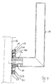
- eine schematische Schnittdarstellung der Vorrichtung nach der Erfindung in Einbaulage;
- Fig. 5
- eine Draufsicht auf die Innenseite einer Abdeckplatte;
- Fig. 6
- einen Schnitt durch die Abdeckplatte;
- Fig. 7
- eine Draufsicht auf eine Halteplatte der Vorrichtung;
- Fig. 8
- eine Draufsicht auf die Innenseite der Halteplatte;
- Fig. 9
- einen Schnitt durch die Halteplatte;
- Fig. 10
- eine Draufsicht auf eine Führungsplatte der Vorrichtung;
- Fig. 11
- einen Schnitt durch die Führungsplatte; und
- Fig. 12
- eine Draufsicht auf einen Führungsschieber der Vorrichtung.
- Fig. 1
- an exploded view of a device according to the invention;
- Fig. 2
- a second exploded view of the device according to the invention;
- Fig. 3
- a third exploded view of the device according to the invention;
- Fig. 4
- a schematic sectional view of the device according to the invention in the installed position;
- Fig. 5
- a plan view of the inside of a cover plate;
- Fig. 6
- a section through the cover plate;
- Fig. 7
- a plan view of a holding plate of the device;
- Fig. 8
- a plan view of the inside of the holding plate;
- Fig. 9
- a section through the retaining plate;
- Fig. 10
- a plan view of a guide plate of the device;
- Fig. 11
- a section through the guide plate; and
- Fig. 12
- a plan view of a guide slide of the device.
In der Zeichnung ist eine Vorrichtung 10 zur lösbaren, axialen Festlegung eines schaftartigen Lagerabschnitts 12 eines Türgriffs 14 dargestellt. Mittels der Vorrichtung 10 kann der Türgriff 14 werkzeugfrei von einem Türblatt 16 gelöst oder mit diesem verbunden werden.In the drawing, a
Die Vorrichtung 10 bildet eine Lagereinheit, die eine Führungshülse 18 aufweist, welche von dem Lagerabschnitt 12 des Türgriffs 14 in dessen Einbaulage durchgriffen ist. Auf die Führungshülse 18 ist in koaxialer Weise eine Führungsplatte 20 aufgesteckt, die zur radialen Führung von zwei Riegelschiebern 22A und 22B dient, die bezogen auf den Lagerabschnitt 12 in radialer Richtung zwischen einer Riegelstellung und einer Freigabestellung verschiebbar sind. An die Führungsplatte 20 schließt sich in axialer Richtung des Lagerabschnitt 12 eine Halteplatte 24 an, mittels der die Vorrichtung 10 an dem Türblatt 16 fixiert werden kann. Die Halteplatte 24 ist wiederum von einer Abdeckung bzw. Blende 26 übergriffen.The
Die Abdeckung 26 ist ringförmig ausgebildet und weist an seinem Umfang einen Ringbund auf. An ihrer Innenseite sind an der Abdeckung 26 zwei Steuerzapfen 28A und 28B ausgeformt, die sich parallel zur Achse des Lagerabschnitts 12 des Türgriffs 14 erstrecken. Des Weiteren sind an der Innenseite der Abdeckung 26 zwei pilzförmige Rastzapfen 30A und 30B ausgebildet. Eine mittlere kreisförmige Aussparung 32 der Abdeckung 26 ist von dem Lagerabschnitt 12 des Türgriffs 14 durchgriffen.The
Die Halteplatte 24 ist ebenfalls ringförmig ausgebildet und weist zur Anbindung an das Türblatt 16 zwei Aufnahmebuchsen bzw. -hülsen 34A und 34B auf, durch die Schrauben gesteckt werden können, die mit dem Türblatt 14 verschraubt werden. Des Weiteren weist die Halteplatte 24 einen Ringbund 36 auf, an dem in der Einbaulage der Umfangsrand der Führungsplatte 20 anliegt, so dass die Führungsplatte 20 von der Halteplatte 24 übergriffen ist. Neben einer zentralen Ausnehmung 38 zum Durchgriff des Lagerabschnitts 12 des Türgriffs 14 weist die Halteplatte 24 zwei bogenförmige Ausnehmungen 40A und 40B auf, die jeweils von einem der Steuerzapfen 28A und 28B der Abdeckung 26 durchgriffen sind. Auf der Kreislinie, auf der auch die Ausnehmungen 40A und 40B liegen, sind zwei weitere Aussparungen 42A und 42B angeordnet, die zur Verrastung der pilzförmigen Rastzapfen 30A und 30B der Abdeckung 26 dienen und hierzu mit einem in radialer Richtung verbreiterten Abschnitt 44 versehen sind, der in Umfangsrichtung über eine Engstelle 46 in einen Rastabschnitt 48 übergeht, in welchem die Rastzapfen 30A und 30B in der Riegelstellung der Riegelschieber 22A und 22B angeordnet sind. Die Rastabschnitte 28 sind von jeweils von einem federelastischen Steg 50 umgeben, so dass die Engstellen 46 bei einer Drehung der Abdeckung 26 gegenüber der Halteplatte 24 von den Rastzapfen 30A und 30B überwunden werden können.The retaining
Die Führungsplatte 20 weist ebenfalls eine zentrale Ausnehmung 52 auf, die von dem Lagerabschnitt 12 des Türgriffs 14 durchgriffen ist. Des Weiteren weist die Führungsplatte 20 zwei Löcher 54A und 54B auf, die jeweils von einer der hülsenförmigen Schraubenaufnahmen 34A und 34B durchgriffen sind. Fluchtend zu den bogenförmigen Ausnehmungen 40A und 40B sind auch an der Führungsplatte 20 bogenförmige Ausnehmungen 57A und 57B ausgebildet, in denen jeweils einer der Steuerzapfen 28A und 28B geführt ist.The
Auf der dem Türblatt 16 abgewandten Seite weist die Führungsplatte 20 zwei Stege 56A und 56B auf, die die Riegelschieber 22A und 22B seitlich begrenzen und diese mithin in radialer Richtung führen.On the side facing away from the
Die Riegelschieber 22A und 22B weisen jeweils eine kreisförmige Stirnseite 58A bzw. 58B auf, die in der Riegelstellung der Riegelschieber 22A und 22B in eine am Umfang des Lagerabschnitts des Türgriffs 14 angeordnete Ringnut 60 eingreift. Des Weiteren weisen die Riegelschieber 22A und 22B jeweils einen als Steuerkulisse ausgebildeten Schlitz 62A bzw. 62B auf, dessen Achse gegenüber der radialen Richtung schräg angestellt ist und der ebenfalls von einem der Steuerzapfen 28A bzw. 28B durchgriffen ist. Durch die Orientierung der Steuerkulissen 62A und 62B kann durch eine Drehung der Abdeckplatte 26 über die Steuerzapfen 28A und 28B eine radiale Verschiebung der Steuerschieber 22A und 22B ausgelöst werden.The locking
Die Festlegung des Türgriffs 14 ab der Vorrichtung 10 erfolgt in nachfolgend beschriebener Weise.The determination of the door handle 14 from the
Zunächst wird die Einheit, die aus der Führungshülse 18 der Führungsplatte 20, den Riegelschiebern 22A und 22B und der Halteplatte 24 besteht, an dem Türblatt 16 verschraubt. Hierbei sollte sichergestellt sein, dass sich die Riegelschieber 22A und 22B jeweils in ihrer Freigabestellung befinden, in der sie außerhalb der zentralen Ausnehmung 52, aber zwischen den Stegen 56A und 56B liegen. Anschließend wird die Abdeckung 26 aufgesetzt, so dass die Steuerzapfen 28A und 28B über die Ausnehmungen 40A und 40B in die Schlitze 62A und 62B der Riegelschieber 22A und 22B eingreifen. Nun kann der Lagerabschnitt 12 des Türgriffs 14 durch die zentralen Ausnehmungen 32, 38, 52 in die Vorrichtung 10 eingeschoben und mit einer Türschlossmechanik gekoppelt werden. Zur Festlegung des Lagerabschnitts 12 des Türgriffs 40 wird die Abdeckung 26 in Uhrzeigerrichtung gedreht, bis die Rastzapfen 30A und 30B in dem Rastabschnitt 48 der Aussparungen 42A und 42B verrastet sind, das heißt die Abdeckung 26 wird in Uhrzeigerrichtung bis auf Anschlag gedreht. Hierdurch werden aufgrund des Zusammenwirkens des Steuerzapfens 28A mit der Steuerkulisse 62A und des Steuerzapfen 28B mit der Steuerkulisse 62B die Riegelschieber 22A und 22B aus ihrer jeweiligen Freigabestellung radial nach innen in ihre Riegelstellung verschoben, in der sie in die Ringnut 60 des Lagerabschnitts 12 des Türgriffs 14 eingreifen. Damit ist der Türgriff 14 verliersicher an die Türschlossmechanik angebunden.First, the unit, which consists of the
Die Demontage des Türgriffs 14 erfolgt in entsprechend umgekehrter Weise.The dismantling of the
Claims (8)
- A device for detachably and axially fixing a bearing section (12) of a handle (14), in particular of a door handle, of a window handle, of a furniture handle or the like, to a bearing unit of a door or a window, said bearing section (12) of the handle (14) comprising a circumferential groove (60) and the bearing unit comprising at least one locking slider (22A, 22B) which can be radially displaced between a locking position and a releasing position and engages into the circumferential groove (60) in order to axially fix the bearing section (12) of the handle (14), said bearing unit comprising an actuating element (26) by means of which the locking slider (22A, 22B) can be radially displaced, characterized in that the locking slider (22A, 22B) comprises a control slot (62A, 62B) into which a control pin (28A, 28B) of the actuating element (26) engages.
- The device according to claim 1, characterized in that the actuating element is a covering panel (26) of the bearing unit, said covering panel (26) being penetrated by the bearing section (12) of the handle (14) and being arranged on the inner side of the control pin (28A, 28B).
- The device according to any one of the claims 1 to 2, characterized in that the actuating element (26) is actuated by being rotated around the axis of the bearing section (12).
- The device according to any one of the claims 1 to 3, characterized by a guide plate (20) for the at least one locking slider (22A, 22B).
- The device according to claim 4, characterized by a retaining plate (24) which is arranged between the actuating element (26) and the guide plate (20) for the locking bar (22A, 22B).
- The device according to claim 4 or 5, characterized in that at least one engagement element, at which the actuating element (26) engages in the locking position of the locking slider (22A, 22B), is realized at the guide plate and/or the retaining plate.
- The device according to claim 6, characterized in that at least one engagement pin (30A, 30B), which interacts with the engagement element, is realized at the actuating element (26).
- The device according to any one of the claims 4 to 7, characterized in that at the guide plate and/or at the retaining plate (24), screw accommodations (34A, 34B) are realized for connecting the bearing unit to the door or the window.
Priority Applications (1)
| Application Number | Priority Date | Filing Date | Title |
|---|---|---|---|
| PL11001670T PL2369099T3 (en) | 2010-03-23 | 2011-03-01 | Door rosette plate |
Applications Claiming Priority (1)
| Application Number | Priority Date | Filing Date | Title |
|---|---|---|---|
| DE201020004053 DE202010004053U1 (en) | 2010-03-23 | 2010-03-23 | door rosette |
Publications (3)
| Publication Number | Publication Date |
|---|---|
| EP2369099A2 EP2369099A2 (en) | 2011-09-28 |
| EP2369099A3 EP2369099A3 (en) | 2015-04-15 |
| EP2369099B1 true EP2369099B1 (en) | 2018-08-22 |
Family
ID=42243951
Family Applications (1)
| Application Number | Title | Priority Date | Filing Date |
|---|---|---|---|
| EP11001670.6A Active EP2369099B1 (en) | 2010-03-23 | 2011-03-01 | Door rosette plate |
Country Status (3)
| Country | Link |
|---|---|
| EP (1) | EP2369099B1 (en) |
| DE (2) | DE202010004053U1 (en) |
| PL (1) | PL2369099T3 (en) |
Families Citing this family (2)
| Publication number | Priority date | Publication date | Assignee | Title |
|---|---|---|---|---|
| MX2020007825A (en) * | 2018-07-12 | 2020-09-25 | Dormakaba Canada Inc | Trim assembly for a door lock and method of assembling a handle thereof. |
| DE102021116534A1 (en) | 2021-06-25 | 2022-12-29 | WILKA Schließtechnik GmbH | door fitting |
Family Cites Families (4)
| Publication number | Priority date | Publication date | Assignee | Title |
|---|---|---|---|---|
| GB371573A (en) * | 1931-03-31 | 1932-04-28 | Robert Benjamin Boden | Improvements in means for securing knobs, handles and the like to spindles |
| US2098868A (en) * | 1936-04-22 | 1937-11-09 | Grimmond Robert | Door handle and like fastening |
| DE10311546A1 (en) | 2003-03-17 | 2004-10-07 | Jado Ag | Device for releasable, axial fixing of a handle on a bearing part, for. B. lever handle or window handle assembly |
| ES2609261T3 (en) * | 2007-09-07 | 2017-04-19 | Dormakaba Deutschland Gmbh | Rosette with a safety device |
-
2010
- 2010-03-23 DE DE201020004053 patent/DE202010004053U1/en not_active Expired - Lifetime
-
2011
- 2011-02-25 DE DE201110012469 patent/DE102011012469A1/en not_active Withdrawn
- 2011-03-01 EP EP11001670.6A patent/EP2369099B1/en active Active
- 2011-03-01 PL PL11001670T patent/PL2369099T3/en unknown
Non-Patent Citations (1)
| Title |
|---|
| None * |
Also Published As
| Publication number | Publication date |
|---|---|
| DE102011012469A1 (en) | 2011-12-15 |
| EP2369099A2 (en) | 2011-09-28 |
| EP2369099A3 (en) | 2015-04-15 |
| PL2369099T3 (en) | 2018-12-31 |
| DE202010004053U1 (en) | 2010-06-10 |
Similar Documents
| Publication | Publication Date | Title |
|---|---|---|
| EP0918655B1 (en) | Coupling device for a vehicle | |
| DE102013202157B4 (en) | Combination padlock with disc shape | |
| EP2796645B1 (en) | Bolt lock of a piece of furniture | |
| EP2906378B1 (en) | Attachment device for a boring system and boring system for boring a connection element | |
| EP2369099B1 (en) | Door rosette plate | |
| DE3833758A1 (en) | FITTING WITH A HANDLE FOR OPERATING THE LOCKNUT OF AN IN A DOOR OD. DGL. INSERTED LOCK | |
| DE102013104874B3 (en) | tool turret | |
| EP1683938B1 (en) | Bolt element for an espagnolette | |
| DE10052495A1 (en) | fastening device | |
| DE202013011573U1 (en) | Handle set for doors | |
| DE4041207C1 (en) | Furniture lock with slide bolt actuated by cylinder or key - has cylinder lock core with drive part angularly adjustable and arrestable in position | |
| EP3363969A1 (en) | Actuation handle | |
| EP2243596A1 (en) | Universal key | |
| DE102017130340A1 (en) | Actuation handle with locking device | |
| DE102007039549A1 (en) | Locking device for gate, door and similar items, has lock cylinder support, which has aperture for receiving lock cylinder, where mounting of lock cylinder is operated in combination module of lock cylinder support by fixed spring | |
| EP3626914B1 (en) | Fitting with a handle and a reset device for the handle, and method for transferring a reset device between a first handle stop position and a second handle stop position | |
| DE102017110754A1 (en) | Tool device, in particular milling tool | |
| EP0853991B1 (en) | Radial rolling head | |
| EP2578891B1 (en) | Adapter | |
| EP0663498A1 (en) | Cylinder lock | |
| DE102016123468B3 (en) | QUICK TURNING TOOL DRIVE | |
| EP2031156A2 (en) | Reset mechanism for a door handle | |
| DE202019104119U1 (en) | Operating unit, locking system and operating unit | |
| DE3210448A1 (en) | Quick-release nut | |
| DE3205133A1 (en) | Device for the angular adjustment of the backrest of a seat, in particular of a motor vehicle seat |
Legal Events
| Date | Code | Title | Description |
|---|---|---|---|
| PUAI | Public reference made under article 153(3) epc to a published international application that has entered the european phase |
Free format text: ORIGINAL CODE: 0009012 |
|
| AK | Designated contracting states |
Kind code of ref document: A2 Designated state(s): AL AT BE BG CH CY CZ DE DK EE ES FI FR GB GR HR HU IE IS IT LI LT LU LV MC MK MT NL NO PL PT RO RS SE SI SK SM TR |
|
| AX | Request for extension of the european patent |
Extension state: BA ME |
|
| PUAL | Search report despatched |
Free format text: ORIGINAL CODE: 0009013 |
|
| AK | Designated contracting states |
Kind code of ref document: A3 Designated state(s): AL AT BE BG CH CY CZ DE DK EE ES FI FR GB GR HR HU IE IS IT LI LT LU LV MC MK MT NL NO PL PT RO RS SE SI SK SM TR |
|
| AX | Request for extension of the european patent |
Extension state: BA ME |
|
| RIC1 | Information provided on ipc code assigned before grant |
Ipc: E05B 3/06 20060101AFI20150310BHEP |
|
| 17P | Request for examination filed |
Effective date: 20150629 |
|
| RAX | Requested extension states of the european patent have changed |
Extension state: BA Payment date: 20150629 Extension state: ME Payment date: 20150629 |
|
| RBV | Designated contracting states (corrected) |
Designated state(s): AL AT BE BG CH CY CZ DE DK EE ES FI FR GB GR HR HU IE IS IT LI LT LU LV MC MK MT NL NO PL PT RO RS SE SI SK SM TR |
|
| GRAP | Despatch of communication of intention to grant a patent |
Free format text: ORIGINAL CODE: EPIDOSNIGR1 |
|
| STAA | Information on the status of an ep patent application or granted ep patent |
Free format text: STATUS: GRANT OF PATENT IS INTENDED |
|
| INTG | Intention to grant announced |
Effective date: 20180319 |
|
| GRAS | Grant fee paid |
Free format text: ORIGINAL CODE: EPIDOSNIGR3 |
|
| GRAA | (expected) grant |
Free format text: ORIGINAL CODE: 0009210 |
|
| STAA | Information on the status of an ep patent application or granted ep patent |
Free format text: STATUS: THE PATENT HAS BEEN GRANTED |
|
| AK | Designated contracting states |
Kind code of ref document: B1 Designated state(s): AL AT BE BG CH CY CZ DE DK EE ES FI FR GB GR HR HU IE IS IT LI LT LU LV MC MK MT NL NO PL PT RO RS SE SI SK SM TR |
|
| AX | Request for extension of the european patent |
Extension state: BA ME |
|
| REG | Reference to a national code |
Ref country code: GB Ref legal event code: FG4D Free format text: NOT ENGLISH |
|
| REG | Reference to a national code |
Ref country code: CH Ref legal event code: EP |
|
| REG | Reference to a national code |
Ref country code: AT Ref legal event code: REF Ref document number: 1032699 Country of ref document: AT Kind code of ref document: T Effective date: 20180915 |
|
| REG | Reference to a national code |
Ref country code: IE Ref legal event code: FG4D Free format text: LANGUAGE OF EP DOCUMENT: GERMAN |
|
| REG | Reference to a national code |
Ref country code: DE Ref legal event code: R096 Ref document number: 502011014616 Country of ref document: DE |
|
| REG | Reference to a national code |
Ref country code: CH Ref legal event code: NV Representative=s name: BODENSEEPATENT PATENTANWAELTE BEHRMANN WAGNER , CH |
|
| REG | Reference to a national code |
Ref country code: NL Ref legal event code: MP Effective date: 20180822 |
|
| REG | Reference to a national code |
Ref country code: LT Ref legal event code: MG4D |
|
| PG25 | Lapsed in a contracting state [announced via postgrant information from national office to epo] |
Ref country code: BG Free format text: LAPSE BECAUSE OF FAILURE TO SUBMIT A TRANSLATION OF THE DESCRIPTION OR TO PAY THE FEE WITHIN THE PRESCRIBED TIME-LIMIT Effective date: 20181122 Ref country code: SE Free format text: LAPSE BECAUSE OF FAILURE TO SUBMIT A TRANSLATION OF THE DESCRIPTION OR TO PAY THE FEE WITHIN THE PRESCRIBED TIME-LIMIT Effective date: 20180822 Ref country code: RS Free format text: LAPSE BECAUSE OF FAILURE TO SUBMIT A TRANSLATION OF THE DESCRIPTION OR TO PAY THE FEE WITHIN THE PRESCRIBED TIME-LIMIT Effective date: 20180822 Ref country code: IS Free format text: LAPSE BECAUSE OF FAILURE TO SUBMIT A TRANSLATION OF THE DESCRIPTION OR TO PAY THE FEE WITHIN THE PRESCRIBED TIME-LIMIT Effective date: 20181222 Ref country code: GR Free format text: LAPSE BECAUSE OF FAILURE TO SUBMIT A TRANSLATION OF THE DESCRIPTION OR TO PAY THE FEE WITHIN THE PRESCRIBED TIME-LIMIT Effective date: 20181123 Ref country code: NO Free format text: LAPSE BECAUSE OF FAILURE TO SUBMIT A TRANSLATION OF THE DESCRIPTION OR TO PAY THE FEE WITHIN THE PRESCRIBED TIME-LIMIT Effective date: 20181122 Ref country code: FI Free format text: LAPSE BECAUSE OF FAILURE TO SUBMIT A TRANSLATION OF THE DESCRIPTION OR TO PAY THE FEE WITHIN THE PRESCRIBED TIME-LIMIT Effective date: 20180822 Ref country code: NL Free format text: LAPSE BECAUSE OF FAILURE TO SUBMIT A TRANSLATION OF THE DESCRIPTION OR TO PAY THE FEE WITHIN THE PRESCRIBED TIME-LIMIT Effective date: 20180822 Ref country code: LT Free format text: LAPSE BECAUSE OF FAILURE TO SUBMIT A TRANSLATION OF THE DESCRIPTION OR TO PAY THE FEE WITHIN THE PRESCRIBED TIME-LIMIT Effective date: 20180822 |
|
| PG25 | Lapsed in a contracting state [announced via postgrant information from national office to epo] |
Ref country code: AL Free format text: LAPSE BECAUSE OF FAILURE TO SUBMIT A TRANSLATION OF THE DESCRIPTION OR TO PAY THE FEE WITHIN THE PRESCRIBED TIME-LIMIT Effective date: 20180822 Ref country code: ES Free format text: LAPSE BECAUSE OF FAILURE TO SUBMIT A TRANSLATION OF THE DESCRIPTION OR TO PAY THE FEE WITHIN THE PRESCRIBED TIME-LIMIT Effective date: 20180822 Ref country code: LV Free format text: LAPSE BECAUSE OF FAILURE TO SUBMIT A TRANSLATION OF THE DESCRIPTION OR TO PAY THE FEE WITHIN THE PRESCRIBED TIME-LIMIT Effective date: 20180822 Ref country code: HR Free format text: LAPSE BECAUSE OF FAILURE TO SUBMIT A TRANSLATION OF THE DESCRIPTION OR TO PAY THE FEE WITHIN THE PRESCRIBED TIME-LIMIT Effective date: 20180822 |
|
| PG25 | Lapsed in a contracting state [announced via postgrant information from national office to epo] |
Ref country code: CZ Free format text: LAPSE BECAUSE OF FAILURE TO SUBMIT A TRANSLATION OF THE DESCRIPTION OR TO PAY THE FEE WITHIN THE PRESCRIBED TIME-LIMIT Effective date: 20180822 Ref country code: RO Free format text: LAPSE BECAUSE OF FAILURE TO SUBMIT A TRANSLATION OF THE DESCRIPTION OR TO PAY THE FEE WITHIN THE PRESCRIBED TIME-LIMIT Effective date: 20180822 Ref country code: EE Free format text: LAPSE BECAUSE OF FAILURE TO SUBMIT A TRANSLATION OF THE DESCRIPTION OR TO PAY THE FEE WITHIN THE PRESCRIBED TIME-LIMIT Effective date: 20180822 |
|
| REG | Reference to a national code |
Ref country code: DE Ref legal event code: R097 Ref document number: 502011014616 Country of ref document: DE |
|
| PG25 | Lapsed in a contracting state [announced via postgrant information from national office to epo] |
Ref country code: SK Free format text: LAPSE BECAUSE OF FAILURE TO SUBMIT A TRANSLATION OF THE DESCRIPTION OR TO PAY THE FEE WITHIN THE PRESCRIBED TIME-LIMIT Effective date: 20180822 Ref country code: DK Free format text: LAPSE BECAUSE OF FAILURE TO SUBMIT A TRANSLATION OF THE DESCRIPTION OR TO PAY THE FEE WITHIN THE PRESCRIBED TIME-LIMIT Effective date: 20180822 Ref country code: SM Free format text: LAPSE BECAUSE OF FAILURE TO SUBMIT A TRANSLATION OF THE DESCRIPTION OR TO PAY THE FEE WITHIN THE PRESCRIBED TIME-LIMIT Effective date: 20180822 |
|
| PLBE | No opposition filed within time limit |
Free format text: ORIGINAL CODE: 0009261 |
|
| STAA | Information on the status of an ep patent application or granted ep patent |
Free format text: STATUS: NO OPPOSITION FILED WITHIN TIME LIMIT |
|
| 26N | No opposition filed |
Effective date: 20190523 |
|
| PG25 | Lapsed in a contracting state [announced via postgrant information from national office to epo] |
Ref country code: SI Free format text: LAPSE BECAUSE OF FAILURE TO SUBMIT A TRANSLATION OF THE DESCRIPTION OR TO PAY THE FEE WITHIN THE PRESCRIBED TIME-LIMIT Effective date: 20180822 |
|
| PG25 | Lapsed in a contracting state [announced via postgrant information from national office to epo] |
Ref country code: MC Free format text: LAPSE BECAUSE OF FAILURE TO SUBMIT A TRANSLATION OF THE DESCRIPTION OR TO PAY THE FEE WITHIN THE PRESCRIBED TIME-LIMIT Effective date: 20180822 |
|
| PG25 | Lapsed in a contracting state [announced via postgrant information from national office to epo] |
Ref country code: LU Free format text: LAPSE BECAUSE OF NON-PAYMENT OF DUE FEES Effective date: 20190301 |
|
| REG | Reference to a national code |
Ref country code: BE Ref legal event code: MM Effective date: 20190331 |
|
| PG25 | Lapsed in a contracting state [announced via postgrant information from national office to epo] |
Ref country code: IE Free format text: LAPSE BECAUSE OF NON-PAYMENT OF DUE FEES Effective date: 20190301 |
|
| PG25 | Lapsed in a contracting state [announced via postgrant information from national office to epo] |
Ref country code: BE Free format text: LAPSE BECAUSE OF NON-PAYMENT OF DUE FEES Effective date: 20190331 |
|
| PG25 | Lapsed in a contracting state [announced via postgrant information from national office to epo] |
Ref country code: TR Free format text: LAPSE BECAUSE OF FAILURE TO SUBMIT A TRANSLATION OF THE DESCRIPTION OR TO PAY THE FEE WITHIN THE PRESCRIBED TIME-LIMIT Effective date: 20180822 |
|
| PGFP | Annual fee paid to national office [announced via postgrant information from national office to epo] |
Ref country code: GB Payment date: 20200325 Year of fee payment: 10 |
|
| PG25 | Lapsed in a contracting state [announced via postgrant information from national office to epo] |
Ref country code: PT Free format text: LAPSE BECAUSE OF FAILURE TO SUBMIT A TRANSLATION OF THE DESCRIPTION OR TO PAY THE FEE WITHIN THE PRESCRIBED TIME-LIMIT Effective date: 20181222 Ref country code: MT Free format text: LAPSE BECAUSE OF FAILURE TO SUBMIT A TRANSLATION OF THE DESCRIPTION OR TO PAY THE FEE WITHIN THE PRESCRIBED TIME-LIMIT Effective date: 20180822 |
|
| PGFP | Annual fee paid to national office [announced via postgrant information from national office to epo] |
Ref country code: FR Payment date: 20200324 Year of fee payment: 10 |
|
| REG | Reference to a national code |
Ref country code: CH Ref legal event code: PFA Owner name: HERMAT METALLWAREN GMBH, DE Free format text: FORMER OWNER: HERMAT METALLWAREN GMBH, DE |
|
| PG25 | Lapsed in a contracting state [announced via postgrant information from national office to epo] |
Ref country code: CY Free format text: LAPSE BECAUSE OF FAILURE TO SUBMIT A TRANSLATION OF THE DESCRIPTION OR TO PAY THE FEE WITHIN THE PRESCRIBED TIME-LIMIT Effective date: 20180822 |
|
| PG25 | Lapsed in a contracting state [announced via postgrant information from national office to epo] |
Ref country code: HU Free format text: LAPSE BECAUSE OF FAILURE TO SUBMIT A TRANSLATION OF THE DESCRIPTION OR TO PAY THE FEE WITHIN THE PRESCRIBED TIME-LIMIT; INVALID AB INITIO Effective date: 20110301 |
|
| GBPC | Gb: european patent ceased through non-payment of renewal fee |
Effective date: 20210301 |
|
| PG25 | Lapsed in a contracting state [announced via postgrant information from national office to epo] |
Ref country code: FR Free format text: LAPSE BECAUSE OF NON-PAYMENT OF DUE FEES Effective date: 20210331 Ref country code: GB Free format text: LAPSE BECAUSE OF NON-PAYMENT OF DUE FEES Effective date: 20210301 |
|
| PGFP | Annual fee paid to national office [announced via postgrant information from national office to epo] |
Ref country code: CH Payment date: 20220324 Year of fee payment: 12 |
|
| PG25 | Lapsed in a contracting state [announced via postgrant information from national office to epo] |
Ref country code: MK Free format text: LAPSE BECAUSE OF FAILURE TO SUBMIT A TRANSLATION OF THE DESCRIPTION OR TO PAY THE FEE WITHIN THE PRESCRIBED TIME-LIMIT Effective date: 20180822 |
|
| PGFP | Annual fee paid to national office [announced via postgrant information from national office to epo] |
Ref country code: IT Payment date: 20220331 Year of fee payment: 12 |
|
| PGFP | Annual fee paid to national office [announced via postgrant information from national office to epo] |
Ref country code: AT Payment date: 20230317 Year of fee payment: 13 |
|
| PGFP | Annual fee paid to national office [announced via postgrant information from national office to epo] |
Ref country code: PL Payment date: 20230216 Year of fee payment: 13 |
|
| P01 | Opt-out of the competence of the unified patent court (upc) registered |
Effective date: 20230524 |
|
| PGFP | Annual fee paid to national office [announced via postgrant information from national office to epo] |
Ref country code: DE Payment date: 20230524 Year of fee payment: 13 |
|
| REG | Reference to a national code |
Ref country code: CH Ref legal event code: PL |
|
| PG25 | Lapsed in a contracting state [announced via postgrant information from national office to epo] |
Ref country code: LI Free format text: LAPSE BECAUSE OF NON-PAYMENT OF DUE FEES Effective date: 20230331 Ref country code: CH Free format text: LAPSE BECAUSE OF NON-PAYMENT OF DUE FEES Effective date: 20230331 |