EP2367780B1 - Verfahren und vorrichtung zum herstellen von dimethylether aus methanol - Google Patents
Verfahren und vorrichtung zum herstellen von dimethylether aus methanol Download PDFInfo
- Publication number
- EP2367780B1 EP2367780B1 EP09775097.0A EP09775097A EP2367780B1 EP 2367780 B1 EP2367780 B1 EP 2367780B1 EP 09775097 A EP09775097 A EP 09775097A EP 2367780 B1 EP2367780 B1 EP 2367780B1
- Authority
- EP
- European Patent Office
- Prior art keywords
- column
- meoh
- dme
- process according
- product
- Prior art date
- Legal status (The legal status is an assumption and is not a legal conclusion. Google has not performed a legal analysis and makes no representation as to the accuracy of the status listed.)
- Active
Links
Images

Classifications
-
- C—CHEMISTRY; METALLURGY
- C07—ORGANIC CHEMISTRY
- C07C—ACYCLIC OR CARBOCYCLIC COMPOUNDS
- C07C41/00—Preparation of ethers; Preparation of compounds having groups, groups or groups
- C07C41/01—Preparation of ethers
- C07C41/09—Preparation of ethers by dehydration of compounds containing hydroxy groups
-
- B—PERFORMING OPERATIONS; TRANSPORTING
- B01—PHYSICAL OR CHEMICAL PROCESSES OR APPARATUS IN GENERAL
- B01D—SEPARATION
- B01D3/00—Distillation or related exchange processes in which liquids are contacted with gaseous media, e.g. stripping
- B01D3/14—Fractional distillation or use of a fractionation or rectification column
- B01D3/143—Fractional distillation or use of a fractionation or rectification column by two or more of a fractionation, separation or rectification step
Definitions
- the invention relates to a process and an apparatus for producing dimethyl ether (DME) from methanol (MeOH) by reacting, preferably by acid-catalytic condensation, MeOH synthesis crude MeOH to DME with elimination of water in a reactor in which the from raw MeOH existing feed mixture and an in-house obtained essentially formed from unreacted MeOH and water of reaction reflux of a column, hereinafter referred to as MeOH column, abandoned and evaporated and the substantially consisting of vaporous MeOH distillate is fed to the reactor.
- DME dimethyl ether
- MeOH column methanol
- MeOH is produced exclusively from the synthesis gases CO 2 / H 2 or CO / H 2 , which in turn come from the reforming of natural gas, residual oils from oil treatment or from the pressure gasification of coal.
- the crude MeOH produced can be further processed directly to DME or worked up by distillation to pure MeOH and then catalytically converted to DME and water.
- the recovered DME product is separated by distillation from unreacted MeOH and water.
- the crude MeOH is subjected to a two- or three-stage distillation in which first the low boilers and the dissolved gases, in particular CO 2 , are removed and then MeOH and water are separated, and the purified MeOH in an adiabatic fixed bed reactor until reaction equilibrium converted to DME.
- the reactor product consists of a mixture of DME, water, unreacted MeOH, and minor amounts of non-condensable light gases
- the reactor product is treated in a two-stage distillation with DME of unreacted MeOH and water of reaction in the first distillation stage in the head and in the second distillation step in the head the MeOH contained in the first stage bottom product of the Reaction water are separated and the recovered MeOH flows back into the reactor.
- the non-condensible light gases discharged at the top of the first distillation stage with the DME are saturated with DME, which is separated from the noncondensable gases in a gas wash with MeOH as a detergent before leaving the system at the top of the gas scrubbing stage as low boilers.
- DME is considered to be a biofuel under the Biofuels Directive 2003/30 / EC of the European Parliament and of the Council on the promotion of the use of biofuels or other renewable fuels in the transport sector, it may contain impurities which are not authorized for high purity DME. It is therefore possible to dispense with the distillation of the MeOH and to pass the crude MeOH directly to the DME reactor. So is in the in the US 5750799 A described process untreated crude MeOH passed directly into a DME reactor, so that the MeOH-containing reflux is loaded with significant amounts of water. This recirculated water must be condensed in addition to the unreacted MeOH and then vaporized in front of the DME reactor, significantly affecting the energy efficiency of the process.
- Crude MeOH contains carbon dioxide H 2 CO 3 as well as small amounts of organic acids which have to be neutralized in order to prevent corrosion on steel apparatuses and apparatus components to avoid the production of DME.
- soda is used to neutralize the raw MeOH.
- the US Pat. No. 6,740,783 B1 describes a process for producing DME from crude MeOH using a DME reactor with a fixed bed of zeolite catalyst, which is first deactivated by doping with metals to increase the DME selectivity of the catalyst.
- a steady supply of metals leads in the long term to a continuous deactivation and thus to a shortening of the lifetime of the catalyst.
- Subject of the EP 1396483 B1 is a process for producing DME in which crude MEOH is dehydrated in the vapor phase in the presence of an activated Na doped Al 2 O 3 catalyst. Care must be taken to a limited Na-doping, so as not to affect the conversion of the catalyst. This means that the crude MeOH must be largely free of metal and NH 4 ions. For the crude MeOH provided and its evaporation, therefore, the entrainment of neutralizing agent should be carefully avoided.
- the JP 2004161672 A discusses a crude MeOH vaporizer which allows partial evaporation of the crude MeOH, with the unvaporized mixture of MeOH and water together with the unreacted MeOH and the water of reaction from the DME reactor in a separate low pressure distillation column in process water and return MeOH is separated.
- the supercooled, low-water, liquid reflux MeOH is contacted with the evaporated crude MeOH to lower the water concentration in the crude MeOH fed to the DME reactor becomes. It is therefore envisaged to conduct unvaporized MeOH to the non-evaporated water of the crude MeOH to the reflux MeOH column.
- the arrangement of a gas scrubber can be dispensed with. Instead, in a final cooler operated with cold water or a refrigerant, the DME discharged with the non-condensable gases can be largely recovered.
- the object underlying the invention is to design the method described above so that the lowest possible consumption of resources achieved, the installed heat exchanger performance improved and the life of the catalyst are not affected.
- reaction mixture withdrawn from the reactor in a column hereinafter referred to as a mixture column is separated into a predominantly consisting of water bottom product and in a predominantly formed from DME and MeOH distillate, the distillate in a column, hereinafter referred to as DME column, into a substantially DME and over Head deliverable non-condensable gas containing distillate and in a low water formed from MeOH bottoms product which is fed to the head of the MeOH column is separated.
- distillate defines the product removed in a distillation or rectification column as a side product or as an overhead product.
- the bottom product formed from low-water MeOH of the DME column is fed to the top of the MeOH column or mixed with the withdrawn from the feed column bottom product.
- the amount of water introduced into the DME column is about the reflux ratio of the generated at the top of the column by condensation of a portion of the top product and at the top of the column abandoned liquid amount and discharged to the DME column Quantity of overhead product adjustable.
- Another feature of the invention is the fact that a portion of the steam generated by evaporation of the reflux of the substantially consisting of water bottoms of the MeOH column steam is passed into the bottom of the mixture column and lowered in this way the DME content in the sump.
- An embodiment of the invention is further to be seen in that condenses the consisting essentially of DME distillate of the DME column and given up part of the condensate as reflux to the head of the DME column and the other part of the DME condensate is discharged. Characterized in that at the same time consisting of low-water liquid MeOH bottom product of the DME column on Head of the MeOH column is abandoned, can be dispensed with the condensation in the MeOH column.
- Another feature of the invention is the fact that the discharged with the non-condensable gases DME in a wash column, preferably with MeOH, washed and passed into the mixture column.
- the gases dissolved therein and light-boiling components are separated in a forerunner column and the distillate is discharged, whereby the quality of the produced DME is improved and the amount of DME entrained with the non-condensable gases from the DME column is reduced.
- the withdrawn from the feed column bottom product is preheated prior to entry into the MeOH column and / or partially evaporated.
- a further embodiment of the process according to the invention consists in the fact that the DME discharged at the top of the DME column with the non-condensable gases is washed out in a wash column, preferably with MeOH, and the produced bottom product is passed into the DME column and / or the crude product. MeOH is added before entering the MeOH column.
- raw MeOH branched off from the feed of the crude MeOH can be introduced as detergent at the top of the wash column.
- the crude methanol contains only small amounts of dissolved gases, can be dispensed with the arrangement of a wash column and instead used with cold water or refrigerant, such as DME, operated end cooler with which the DME discharged with the non-condensable gases can be recovered.
- cold water or refrigerant such as DME
- the bottom product of the MeOH column which consists predominantly of water, is discharged from the process or fed to the lower part of the mixture column and then discharged via the bottom of the mixture column.
- a portion of the gaseous distillate of the MeOH column is passed into the bottom of the DME column.
- the DME column is arranged on the MeOH column.
- the two columns are coupled via the distillate of the MeOH column and the bottom product of the DME column, so that the MeOH column without reflux condenser and the DME column can be operated without an evaporator.
- a modification of the process according to the invention consists in that the vaporous distillate of the mixture column predominantly consisting of DME and MeOH enters the bottom of a rectification column, hereinafter referred to as DME product column is fed, the liquid MeOH-containing bottom product of this column at the top of a rectification column, hereinafter referred to as MeOH-reflux column is charged, with their distillate passed into the bottom of the DME product column and its bottom product the head of MeOH Column is supplied.
- the DME product column designed as a reinforcing part is arranged on the mixture column and the MeOH reflux column formed as a stripping section is arranged on the MeOH column.
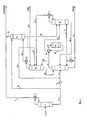
- Fig. 1 is fed from crude MeOH with a MeOH content of 75 wt.%
- Feed stream via line (1) in the feed column (2) is fed in at an average temperature of 80 ° C and a mean pressure of 3 bar [a] the gases dissolved in the crude MeOH, such as CO, CO 2 , CH 4 and the low-boiling hydrocarbons, are discharged for further use via line (3).
- the gas mixture withdrawn at the bottom of the reactor (12) is fed via line (13) to the heat exchanger group (10) and recuperatively cooled before being fed via line (14) to the mixture column (15).
- the gas mixture is separated at a mean pressure of 15 bar [a] and an average temperature of 150 ° C in a water-rich bottom product and in a low-water overhead product, wherein the top product is less than 5 wt.%, preferably less than 2% by weight, contains water.
- the water-rich bottom product is passed via line (16) to the MeOH column (7).
- the low-water top product is fed via line (17) of the DME column (18), which operates at an average temperature of 100 ° C and a pressure of 13.5 bar [a].
- DME is withdrawn and passed via line (19) to the plant boundary.
- the bottom product of the DME column (18) consisting predominantly of MeOH with small amounts of water is pumped via line (20) to the top of the MeOH column (7) and serves as reflux for the enrichment section of the MeOH column (7).
- a partial stream of the top product of the MeOH column (7) flowing in line (9) can be branched off and fed via line (21) into the bottom of the DME column.
- Column (18) are introduced, so that can be dispensed with in this case to an evaporator circuit.
- the non-condensable gases in the DME column (18) are withdrawn overhead and passed via line (22) in the bottom of the washing stage (23), in which at an average pressure of 10 bar [a] and a mean temperature of 75 ° C, the DME contained in the non-condensable gases with branched off from the line (4) and recovered via line (24) at the top of the washing stage (23) MeOH is recovered.
- the gaseous top product of the washing stage (23) is combined via line (25) with the top product of the feed column (2) flowing off via line (3) and discharged for other use.
- the DME-containing detergent is pumped from the bottom of the washing stage (23) via line (26) in the mixture column (15).
- the bottom product of the washing stage (23) via line (27) either in the DME column (18) or via line (28) in the line (6) of the MeOH column (7) inflowing MeOH stream can be fed.
- the mixture column (15) can be operated without evaporator circuit.
- the water-lean product discharged via the line (17) from the top of the mixture column (15) is passed directly into the bottom of a rectification column (30), designed as a reinforcing column on the mixture column (15), hereinafter referred to as a DME product column.
- the bottom product of the DME product column (30) consisting predominantly of MeOH with small amounts of water is passed via line (31) to the top of a column (32) arranged on the MeOH column (7) as a stripping column, subsequently as MeOH.
- Reverse column referred fed.
- the bottom product of the MeOH reflux column (32) flows via line (20) to the top of the MeOH column (7), while the top product is passed via line (33) into the bottom of the DME product column (30).
- the partial stream branched off from the top product of the MeOH column (9) flowing in line (9) is fed via line (21) to the bottom of the MeOH return column (32).
Landscapes
- Chemical & Material Sciences (AREA)
- Organic Chemistry (AREA)
- Chemical Kinetics & Catalysis (AREA)
- Organic Low-Molecular-Weight Compounds And Preparation Thereof (AREA)
Description
- Die Erfindung betrifft ein Verfahren und eine Vorrichtung zum Herstellen von Dimethylether (DME) aus Methanol (MeOH) durch Umsetzen, vorzugsweise durch säurenkatalytische Kondensation, von durch MeOH-Synthese gewonnenem Roh-MeOH zu DME unter Abspalten von Wasser in einem Reaktor, bei dem das aus Roh-MeOH bestehende Einsatzgemisch und ein prozessintern gewonnener im wesentlichen aus nicht umgesetztem MeOH und Reaktionswasser gebildeter Rückfluss einer Kolonne, nachfolgend als MeOH-Kolonne bezeichnet, aufgegeben und verdampft werden und das im wesentlichen aus dampfförmigem MeOH bestehende Destillat dem Reaktor zugeführt wird.
- MeOH wird heute ausschließlich aus den Synthesegasen CO2/H2 oder CO/H2 hergestellt, die ihrerseits aus der Reformierung von Erdgas, Rückstandsölen der Erdölaufbereitung oder aus der Druckvergasung von Kohle stammen. Das erzeugte Roh-MeOH kann unmittelbar zu DME weiterverarbeitet oder destillativ zu Rein-MeOH aufgearbeitet und anschließend katalytisch zu DME und Wasser umgesetzt werden. In beiden Fällen wird das gewonnene DME-Produkt destillativ von nicht umgesetztem MeOH und Wasser getrennt. In aller Regel wird das Roh-MeOH einer zwei- oder dreistufigen Destillation, in der zunächst die Leichtsieder und die gelösten Gase, insbesondere CO2, entfernt und dann MeOH und Wasser getrennt werden, unterworfen und das gereinigte MeOH in einem adiabaten Festbettreaktor bis zum Reaktionsgleichgewicht zu DME umgesetzt. Da das Reaktorprodukt aus einem Gemisch von DME, Wasser, nicht-umgesetztem MeOH und kleineren Mengen nichtkondensierbarer leichter Gase besteht, wird das Reaktorprodukt in einer zweistufigen Destillation behandelt, wobei in der ersten Destillationsstufe im Kopf DME von nicht-umgesetztem MeOH und Reaktionswasser und in der zweiten Destillationsstufe im Kopf das in dem Sumpfprodukt der ersten Stufe enthaltene MeOH von dem Reaktionswasser getrennt werden und das gewonnene MeOH zurück in den Reaktor fließt. Die am Kopf der ersten Destillationsstufe mit dem DME ausgetragenen nicht-kondensierbaren leichten Gase sind mit DME gesättigt, das in einer Gaswaschstufe mit MeOH als Waschmittel von den nicht-kondensierbaren Gasen getrennt wird, bevor diese als Leichtsieder das System am Kopf die Gaswaschstufe verlassen. Es werden demnach sowohl bei der Destillation von DME als auch bei der Destillation von MeOH, vorwiegend aus MeOH, Wasser und DME bestehende Stoffgemische, getrennt. Da die Produktspezifikationen für DME einerseits und MeOH andererseits verschiedenen Erfordernissen genügen müssen, werden die Destillationen von DME und MeOH separat durchgeführt. Die vorstehend beschriebenen Maßnahmen werden insbesondere für das Herstellen von hochreinem DME, der breite Anwendung als Treibgas, z.B. in Haarspray und Lackspray findet, angewendet. Technischer DME ist eine Alternative zu Flüssiggasen mit ausgezeichneten Brenneigenschaften. Aufgrund einer Cetanzahl von 55 bis 60 lässt sich DME in Dieselmotoren als Ersatz für Dieselkraftstoff einsetzen.
- Da gemäß der Biokraftstoffrichtlinie 2003/30/EG des Europäischen Parlaments und des Rates zur "Förderung der Verwendung von Biokraftstoffen oder anderen erneuerbaren Kraftstoffen im Verkehrssektor" DME als Biokraftstoff gilt, darf dieser Verunreinigungen enthalten, die bei hochreinem DME nicht zugelassen sind. Es kann daher auf die Destillation des MeOH verzichtet und das Roh-MeOH direkt dem DME-Reaktor aufgegeben werden. So wird bei dem in der
US 5750799 A beschriebenen Verfahren unbehandeltes Roh-MeOH direkt in einen DME-Reaktor geleitet, so dass der das MeOH enthaltende Rücklauf mit erheblichen Wassermengen belastet ist. Dieses im Kreislauf geführte Wasser muss zusätzlich zum nicht-umgesetzten MeOH kondensiert und anschließend vor dem DME-Reaktor verdampft werden, wodurch die Energieeffiziens des Verfahrens beachtlich beeinträchtigt wird. Außerdem wird durch den verminderten MeOH-Umsatz im DME-Reaktor der Kreislaufstrom vergrößert und demzufolge müssen die Apparate und apparatetechnischen Komponenten der Anlage zum Herstellen von DME größer ausgebildet werden. Roh-MeOH enthält Kohlensäure H2CO3 sowie geringe Mengen organischer Säuren, die neutralisiert werden müssen, um Korrosionserscheinungen an aus Stahl bestehenden Apparaten und apparatetechnischen Komponenten für das Herstellen von DME zu vermeiden. Zur Neutralisation des Roh-MeOH wird üblicherweise Soda eingesetzt. - Die
US 6740783 B1 beschreibt ein Verfahren zur Herstellung von DME aus Roh-MeOH unter Verwendung eines DME-Reaktors mit einem Festbett aus ZeolithKatalysator, der zunächst durch eine Dotierung mit Metallen deaktiviert wird, um die DME-Selektivität des Katalysators zu steigern. Eine stetige Zufuhr von Metallen führt jedoch langfristig zu einer kontinuierlichen Deaktivierung und damit zu einer Verkürzung der Lebensdauer des Katalysators. Gegenstand derEP 1396483 B1 ist ein Verfahren zur Herstellung von DME, bei dem Roh-MEOH in der Dampfphase in Gegenwart eines aktivierten mit Na dotierten Al2O3-Katalysators dehydratisiert wird. Dabei muss auf eine begrenzte Na-Dotierung geachtet werden, um den Umsatz des Katalysators nicht zu beeinträchtigen. Das bedeutet, dass das Roh-MeOH weitgehend frei von Metall- und NH4-Ionen sein muss. Bei dem bereitgestellten Roh-MeOH und dessen Verdampfung ist daher der Mitriss von Neutralisierungsmittel sorgfältig zu vermeiden. - In den Druckschriften
CN 100366597 C ,CN 1830934 A undJP 2004161673 A JP 2004161672 A - Aus der
EP 455004 A1 US 5750799 A ist bekannt, das mit den nicht-kondensierbaren Gasen am Kopf der DME-Kolonne ausgetragene DME in einer Kolonne auszuwaschen und zur MeOH-Kolonne zurückzuführen. Diese Maßnahme führt zu einem DME-Gehalt in dem dem DME-Reaktor aufgegebenen Roh-MeOH, durch den der Umsatz von MeOH zu DME reduziert wird. Dies ist insbesondere relevant, wenn Roh-MeOH eingesetzt wird, und die in dem Roh-MeOH enthaltenen leichten Gase nicht vor dem DME-Reaktor sondern erst in der DME-Kolonne abgetrennt werden. Proportional zur Menge der nicht-kondensierten leichten Gase steigt die Menge des mit den Gasen ausgetragenen DME und damit die Menge an DME im Zulauf zum DME-Reaktor an. - Wenn das Roh-MeOH nur wenig gelöste Gase enthält, kann auf die Anordnung eines Gaswäschers verzichtet werden. Stattdessen kann in einem mit Kaltwasser oder einem Kältemittel betriebenen Endkühler das mit den nicht-kondensierbaren Gasen ausgetragene DME weitgehend zurückgewonnen werden.
- Die der Erfindung zugrundeliegende Aufgabe besteht darin, das eingangs beschriebene Verfahren so zu gestalten, dass ein möglichst niedriger Verbrauch an Betriebsmitteln erreicht, die installierte Wärmeübertragerleistung verbessert und die Lebensdauer des Katalysators nicht beeinträchtigt werden.
- Gelöst ist diese Aufgabe dadurch, dass das aus dem Reaktor abgezogene Reaktionsgemisch in einer Kolonne, nachfolgend als Gemisch-Kolonne bezeichnet, in ein überwiegend aus Wasser bestehendes Sumpfprodukt und in ein überwiegend aus DME und MeOH gebildetes Destillat getrennt wird, das Destillat in einer Kolonne, nachfolgend als DME-Kolonne bezeichnet, in ein im wesentlichen DME und über Kopf abgebbare nicht-kondensierbare Gase enthaltendes Destillat und in ein aus wasserarmem MeOH gebildetes Sumpfprodukt, das dem Kopf der MeOH-Kolonne zugeführt wird, getrennt wird.
- Das Begriff "Destillat" definiert das bei einer Destillations- bzw. Rektifikationskolonne als Seitenprodukt oder als Kopfprodukt abgenommene Erzeugnis.
- Im Rahmen der Ausgestaltung des Erfindung wird das aus wasserarmem MeOH gebildete Sumpfprodukt der DME-Kolonne dem Kopf der MeOH-Kolonne zugeleitet oder mit dem aus der Vorlaufkolonne abgezogenen Sumpfprodukt gemischt.
- Nach einem weiteren Erfindungsmerkmal besteht die Möglichkeit, das aus dem Reaktor abgezogene Reaktionsgemisch in einem prozessinternen Wärmeübertrager abzukühlen oder teilweise zu kondensieren, bevor das Reaktionsgemisch der Gemisch-Kolonne aufgegeben wird.
- Die Wassermenge des in die DME-Kolonne eingeleiteten, überwiegend aus DME und MeOH bestehenden Destillats der Gemisch-Kolonne, ist über das Rücklaufverhältnis von der am Kolonnenkopf durch Kondensation eines Teils des Kopfprodukts erzeugter und am Kolonnenkopf wieder aufgegebener Flüssigkeitsmenge und der zur DME-Kolonne abgeführten Kopfproduktmenge einstellbar. Durch diese Maßnahme lässt sich die Qualität des aus dem Sumpf der DME-Kolonne abgezogenen wasserarmen flüssigen Rücklauf-MeOH optimieren.
- Ein weiteres Erfindungsmerkmal ist darin zu sehen, dass ein Teil des durch Verdampfen des Rücklaufs des im wesentlichen aus Wasser bestehenden Sumpfprodukts der MeOH-Kolonne erzeugten Dampfs in den Sumpf der Gemisch-Kolonne geleitet und auf diese Weise der DME-Gehalt im Sumpf gesenkt wird.
- Eine Ausgestaltung der Erfindung ist ferner darin zu sehen, dass das im wesentlichen aus DME bestehende Destillat der DME-Kolonne kondensiert und ein Teil des Kondensats als Rücklauf dem Kopf der DME-Kolonne aufgegeben und der andere Teil des DME-Kondensats ausgeleitet wird. Dadurch, dass gleichzeitig das aus wasserarmem flüssigen MeOH bestehende Sumpfprodukt der DME-Kolonne am Kopf der MeOH-Kolonne aufgegeben wird, kann auf die Kondensation in der MeOH-Kolonne verzichtet werden.
- Es besteht auch die Möglichkeit, das in der DME-Kolonne kondensierte DME als Seitenprodukt aus dem Verstärkungsteil der DME-Kolonne auszuleiten.
- Ein weiteres Merkmal der Erfindung ist darin zu sehen, dass das mit den nicht-kondensierbaren Gasen ausgetragene DME in einer Waschkolonne, vorzugsweise mit MeOH, ausgewaschen und in die Gemisch-Kolonne geleitet wird.
- Im Rahmen der zusätzlichen Ausgestaltung der Erfindung werden vor dem Verdampfen des MeOH in der MeOH-Kolonne von dem zulaufenden Roh-MeOH die darin gelösten Gasen und leicht-siedenden Komponenten in einer Vorlaufkolonne abgetrennt und das Destillat ausgeleitet, wodurch die Qualität des erzeugten DME verbessert und die mit den nicht-kondensierbaren Gasen aus der DME-Kolonne mitgeschleppte DME-Menge verkleinert wird.
- Das aus der Vorlaufkolonne abgezogene Sumpfprodukt wird vor dem Einlauf in die MeOH-Kolonne vorgewärmt und/oder teilweise verdampft.
- Eine Ausgestaltung des erfindungsgemäßen Verfahrens besteht ferner darin, dass das am Kopf der DME-Kolonne mit den nicht-kondensierbaren Gasen ausgetragene DME in einer Waschkolonne, vorzugsweise mit MeOH, ausgewaschen und das erzeugtes Sumpfprodukt in die DME-Kolonne geleitet und/oder dem Roh-MeOH vor dem Eintritt in die MeOH-Kolonne zugesetzt wird.
- Nach einem weiteren Erfindungsmerkmal kann von dem Zulauf des Roh-MeOH abgezweigtes Roh-MeOH als Waschmittel am Kopf der Waschkolonne aufgegeben werden.
- Wenn das Roh-Methanol nur geringe Mengen gelöste Gase enthält, kann auf die Anordnung einer Waschkolonne verzichtet werden und stattdessen ein mit Kaltwasser oder Kältemittel, beispielsweise DME, betriebener Endkühler eingesetzt werden, mit dem sich das mit den nicht kondensierbaren Gasen ausgetragene DME zurückgewinnen lässt.
- Es ist zweckmäßig, das gelöste Gase und leicht-siedende Komponenten enthaltende Destillat der Vorlaufkolonne mit dem nicht-kondensierbare Gase enthaltenden Destillat der Waschkolonne zusammenzuführen und das Gemisch zur Weiterverarbeitung auszuleiten.
- Nach einem zusätzlichen Erfindungsmerkmal wird das überwiegend aus Wasser bestehende Sumpfprodukt der MeOH-Kolonne aus dem Prozess ausgeleitet oder dem unteren Teil der Gemisch-Kolonne zugeführt und dann über den Sumpf der Gemisch-Kolonne ausgeleitet.
- Es besteht auch die Möglichkeit, das überwiegend aus Wasser bestehende Sumpfprodukt der Gemisch-Kolonne in die MeOH-Kolonne zu leiten und das Wasser über den Sumpf der MeOH-Kolonne aus dem Prozess auszuleiten.
- Es ist von Vorteil, das MeOH enthaltende Destillat der MeOH-Kolnne vor dem Einleiten in den Reaktor durch indirekte Wärmeübertragung von der in dem aus dem Reaktor ausgetragenen Reaktionsgemisch enthaltenen Reaktionswärme auf eine Reaktionstemperatur von 250 bis 330° C zu überhitzen.
- Ein Teil des gasförmigen Destillats der MeOH-Kolonne wird in den Sumpf der DME-Kolonne geleitet.
- Bei der Vorrichtung zur Durchführung des Verfahrens ist erfindungsgemäß die DME-Kolonne auf der MeOH-Kolonne angeordnet. Die beiden Kolonnen sind über das Destillat der MeOH-Kolonne und das Sumpfprodukt der DME-Kolonne gekoppelt, so dass die MeOH-Kolonne ohne Rücklaufkühler und die DME-Kolonne ohne Verdampfer betrieben werden können.
- Eine Abwandlung des erfindungsgemäßen Verfahrens besteht darin, dass dampfförmige überwiegend aus DME und MeOH bestehende Destillat der Gemisch-Kolonne in den Sumpf einer Rektifikationskolonne, nachfolgend als DME-Produkt-Kolonne bezeichnet, eingespeist wird, das flüssiges MeOH enthaltende Sumpfprodukt dieser Kolonne am Kopf einer Rektifikationskolonne, nachfolgend als MeOH-Rücklauf-Kolonne bezeichnet, aufgegeben wird, wobei deren Destillat in den Sumpf der DME-Produkt-Kolonne geleitet und deren Sumpfprodukt dem Kopf der MeOH-Kolonne zugeführt wird.
- Bei der erfindungsgemäßen Abwandlung des Verfahrens sind die als Verstärkungsteil ausgebildete DME-Produkt-Kolonne auf der Gemisch-Kolonne und die als Abtriebsteil ausgebildete MeOH-Rücklauf-Kolonne auf der MeOH-Kolonne angeordnet. Durch diese Maßnahme sind praktisch der Verstärkungsteil und der Abtriebsteil der DME-Kolonne getrennt und der kleinere Abtriebsteil der DME-Kolonne lässt sich auf die Methanol-Kolonne und der größere Verstärkungsteil der DME-Kolonne auf die Gemisch-Kolonne stellen. Der Durchmesser von Gemisch-Kolonne und Verstärkungsteil der DME-Kolonne sind nahezu gleich groß.
- Weitere Merkmale, Vorteile und Anwendungsmöglichkeiten des erfindungsgemäßen Verfahrens ergeben sich auch aus der nachfolgenden Beschreibung eines Ausführungsbeispiels und der in der Zeichnung in
Fig. 1 undFig. 2 dargestellten apparativen Verfahrensfließbilder. Dabei bilden alle beschriebenen und/oder bildlich dargestellten Merkmale für sich oder in beliebiger Kombination den Gegenstand der Erfindung, unabhängig von ihrer Zusammenfassung in den Ansprüchen oder deren Rückbeziehung. - Gemäß
Fig. 1 wird ein aus Roh-MeOH mit einem MeOH-Gehalt von 75 Gew. % bestehender Einsatzstrom über Leitung (1) in die Vorlauf-Kolonne (2) eingespeist, in der bei einer mittleren Temperatur von 80° C und einem mittleren Druck von 3 bar[a] die in dem Roh-MeOH gelösten Gase, wie CO, CO2, CH4 und die leichtsiedenden Kohlenwasserstoffe und über Leitung (3) zur anderweitigen Nutzung ausgeleitet werden. Das mit einer mittleren Temperatur von 100° C vom Sumpf der Vorlaufkolonne (2) über Leitung (4) abgezogene MeOH wird in einer Wärmeübertragergruppe (5) auf eine mittlere Temperatur von 160° C vorgewärmt, dabei teilweise verdampft und über Leitung (6) einer MeOH-Kolonne (7) aufgegeben, in der bei einer mittleren Temperatur von 180° C und einem mittleren Druck von 20 bar[a] das Wasser vom MeOH abgetrennt wird. Aus dem Sumpf der MeOH-Kolonne (7) wird das Wasser über Leitung (8) aus dem Prozess ausgeleitet, während das über Leitung (9) abgeführte gasförmige eine mittlere Temperatur von 170° C besitzende Kopfprodukt der MeOH-Kolonne in einer Wärmeübertragergruppe (10) auf eine mittlere Temperatur von 300° C erwärmt und über Leitung (11) in einen Reaktor (12) geleitet wird. Das am Boden des Reaktors (12) abgezogene Gasgemisch wird über Leitung (13) der Wärmeübertragergruppe (10) zugeführt und rekuperativ gekühlt, bevor es über Leitung (14) der Gemisch-Kolonne (15) aufgegeben wird. In der Gemisch-Kolonne (15) wird das Gasgemisch bei einem mittleren Druck von 15 bar[a] und einer mittleren Temperatur von 150° C in ein wasserreiches Sumpfprodukt und in ein wasserarmes Kopfprodukt getrennt, wobei das Kopfprodukt weniger als 5 Gew. %, vorzugsweise weniger als 2 Gew. %, Wasser enthält. Das wasserreiche Sumpfprodukt wird über Leitung (16) zur MeOH-Kolonne (7) geleitet. Das wasserarme Kopfprodukt wird über Leitung (17) der DME-Kolonne (18), die bei einer mittleren Temperatur von 100° C und einem Druck von 13,5 bar[a] arbeitet, zugeführt. Vom Kopf der DME-Kolonne (18) oder von der Seite, zwei bis sieben Böden unterhalb des Kopfkondensators, wird DME abgezogen und über Leitung (19) zur Anlagengrenze geleitet. Das überwiegend aus MeOH mit kleinen Mengen an Wasser bestehende Sumpfprodukt der DME-Kolonne (18) wird über Leitung (20) zum Kopf der MeOH-Kolonne (7) gepumpt und dient als Rückfluss für den Verstärkungsteil der MeOH-Kolonne (7). Um die Konzentration von DME im Sumpf der DME-Kolonne (18) möglichst klein zu halten, kann ein Teilstrom des in Leitung (9) strömenden Kopfprodukts der MeOH-Kolonne (7) abgezweigt und über Leitung (21) in den Sumpf der DME-Kolonne (18) eingeleitet werden, so dass in diesem Fall auf einen Verdampferkreislauf verzichtet werden kann. - Die in der DME-Kolonne (18) nicht-kondensierbaren Gase werden über Kopf abgezogen und über Leitung (22) in den Sumpf der Waschstufe (23) geleitet, in der bei einem mittleren Druck von 10 bar[a] und einer mittleren Temperatur von 75° C das in den nicht-kondensierbaren Gasen enthaltene DME mit aus der Leitung (4) abgezweigtem und über Leitung (24) am Kopf der Waschstufe (23) aufgegebenem MeOH zurückgewonnen wird. Das gasförmige Kopfprodukt der Waschstufe (23) wird über Leitung (25) mit dem über Leitung (3) abströmenden Kopfprodukt der Vorlaufkolonne (2) zusammengeführt und zur anderweitigen Benutzung ausgeleitet. Das DME enthaltende Waschmittel wird aus dem Sumpf der Waschstufe (23) über Leitung (26) in die Gemisch-Kolonne (15) gepumpt. Alternativ kann das Sumpfprodukt der Waschstufe (23) über Leitung (27) entweder in die DME-Kolonne (18) oder über Leitung (28) in den in Leitung (6) der MeOH-Kolonne (7) zuströmenden MeOH-Strom eingespeist werden. Die Gemisch-Kolonne (15) kann ohne Verdampferkreislauf betrieben werden.
- Bei der in
Fig. 2 wiedergegebenen Abwandlung des Verfahrensfließbilds nachFig. 1 wird das über Leitung (17) vom Kopf der Gemisch-Kolonne (15) abgeführte wasserarme Produkt unmittelbar in den Sumpf einer als Verstärkungskolonne ausgebildeten auf der Gemischkolonne (15) angebrachten Rektifikationskolonne (30), nachfolgend als DME-Produkt-Kolonne bezeichnet, geleitet. Das überwiegend aus MeOH mit kleinen Mengen an Wasser bestehende Sumpfprodukt der DME-Produkt-Kolonne (30) wird über Leitung (31) dem Kopf einer auf der MeOH-Kolonne (7) angeordneten als Abtriebskolonne ausgebildeten Kolonne (32), nachfolgend als MeOH-Rücklauf-Kolonne bezeichnet, zugeführt. Das Sumpfprodukt der MeOH-Rücklauf-Kolonne (32) strömt über Leitung (20) zum Kopf der MeOH-Kolonne (7), während das Kopfprodukt über Leitung (33) in den Sumpf der DME-Produkt-Kolonne (30) geleitet wird. Der von dem in Leitung (9) fließenden Kopfprodukt der MeOH-Kolonne (9) abgezweigte Teilstrom wird über Leitung (21) dem Sumpf der MeOH-Rücklauf-Kolonne (32) zugeführt. - Die mit der Erfindung erzielten Vorteile sind insbesondere in einer vergleichsweise verbesserten Energieeffizienz und Wirtschaftlichkeit zu sehen. Ein Vergleich des erfindungsgemäßen Verfahrens mit einem bekannten zum Stand der Technik gehörenden Verfahren, wie dieses beispielsweise in der
JP 2004161672 A
Claims (17)
- Verfahren zum Herstellen von Dimethylether (DME) aus Methanol (MeOH), durch Umsetzen, vorzugsweise durch säurenkatalytische Kondensation, von durch MeOH-Synthese gewonnenem Roh-MeOH zu DME unter Abspalten von Wasser in einem Reaktor (12), bei dem das aus Roh-MeOH bestehende Einsatzgemisch und wenigstens ein prozessintern gewonnener im wesentlichen aus nicht umgesetztem MeOH und Reaktionswasser gebildeter Rückfluss einer MeOH-Kolonne (7) aufgegeben und verdampft werden und das im wesentlichen aus dampfförmigem MeOH bestehende Destillat dem Reaktor zugeführt wird, dadurch gekennzeichnet, dass das aus dem Reaktor (12) abgezogene Reaktionsgemisch in einer Gemisch-Kolonne (15) in ein überwiegend aus Wasser bestehendes Sumpfprodukt und in ein überwiegend aus DME und MeOH gebildetes Destillat getrennt wird, das Destillat in einer DME-Kolonne (18) in ein im wesentlichen DME und über Kopf abgegebene nicht-kondensierbare Gase enthaltendes Destillat und in ein aus wasserarmem MeOH gebildetes Sumpfprodukt, das dem Kopf der MeOH-Kolonne (7) zugeführt oder mit dem aus der Vorlauf-Kolonne (2) abgezogenen Sumpfprodukt gemischt wird, getrennt wird.
- Verfahren nach Anspruch 1, dadurch gekennzeichnet, dass das aus dem Reaktor (12) abgezogene Reaktionsgemisch in einem prozessinternen Wärmeübertrager (10) abgekühlt oder teilkondensiert wird, bevor es Gemisch-Kolonne (15) aufgegeben wird.
- Verfahren nach einem der Ansprüche 1 und 2, dadurch gekennzeichnet, dass die Wassermenge des der DME-Kolonne (18) zugeführten überwiegend aus DME und MeOH bestehenden Destillats der Gemisch-Kolonne (15) über das Rücklaufverhältnis von der am Kolonnenkopf durch Kondensation eines Teils des Kopfprodukts erzeugter am Kolonnenkopf wieder aufgegebener Flüssigkeitsmenge und der zur DME-Kolonne abgeführten Kopfproduktmenge einstellbar ist.
- Verfahren nach einem der Ansprüche 1 bis 3, dadurch gekennzeichnet, dass ein Teil des durch Verdampfen des Rücklaufs des im wesentlichen aus Wasser bestehenden Sumpfprodukts der MeOH-Kolonne (7) erzeugten Dampfs in den Sumpf der Gemisch-Kolonne (15) geleitet wird.
- Verfahren nach einem der Ansprüche 1 bis 4, dadurch gekennzeichnet, dass das im wesentlichen aus DME bestehende Destillat der DME-Kolonne (18) kondensiert und ein Teil des Kondensats als Rücklauf dem Kopf der DME-Kolonne aufgegeben und der andere Teil ausgeleitet wird.
- Verfahren nach einem der Ansprüche 1 bis 5, dadurch gekennzeichnet, dass das in der DME-Kolonne (18) kondensierte DME als Seitenprodukt aus dem Auftriebsteil der DME-Kolonne ausgeleitet wird.
- Verfahren nach einem der Ansprüche 1 bis 6, dadurch gekennzeichnet, dass das mit den nicht-kondensierbaren Gasen aus der DME-Kolonne (18) ausgetragene DME in einer Waschkolonne (23), vorzugsweise mit MeOH, ausgewaschen und in die Gemisch-Kolonne (15) geleitet wird.
- Verfahren nach einem der Ansprüche 1 bis 7, dadurch gekennzeichnet, dass von dem Zulauf an zu trennendem Roh-MeOH vor dem Verdampfen des MeOH in der MeOH-Kolonne (7) die in dem Roh-MeOH gelösten Gase und leicht-siedenden Komponenten in einer Vorlaufkolonne (2) abgetrennt und das Destillat aus dem Prozess ausgeleitet wird.
- Verfahren nach einem der Ansprüche 1 bis 8, dadurch gekennzeichnet, dass der Zulauf an zu trennendem Roh-MeOH vor der MeOH-Kolonne (7) vorgewärmt und/oder teilweise verdampft wird.
- Verfahren nach einem der Ansprüche 1 bis 9, dadurch gekennzeichnet, dass das mit nicht-kondensierbaren Gasen aus der DME-Kolonne (18) ausgetragene DME in einer Waschkolonne (23), vorzugsweise mit MeOH, ausgewaschen und das erzeugte Sumpfprodukt in die DME-Kolonne (18) geleitet und/oder dem Roh-MeOH vor dem Eintritt in die MeOH-Kolonne (7) zugesetzt wird.
- Verfahren nach einem der Ansprüche 1 bis 10, dadurch gekennzeichnet, dass als Waschmittel von dem Zulauf an MeOH abgezweigtes Roh-MeOH am Kopf der Waschkolonne(23) aufgegeben wird oder ein Teilstrom des Sumpfprodukts der DME-Kolonne (18) eingesetzt wird.
- Verfahren nach einem der Ansprüche 1 bis 11, dadurch gekennzeichnet, dass das gelöste Gase und leicht-siedende Komponenten enthaltende Destillat der Vorlaufkolonne (2) mit dem nicht-kondensierbare Gase enthalten Kopfprodukt der Waschkolonne (23) zusammengeführt wird.
- Verfahren nach einem der Ansprüche 1 bis 12, dadurch gekennzeichnet, dass das überwiegend aus Wasser bestehende Sumpfprodukt der MeOH-Kolonne (7) in den unteren Teil der Gemisch-Kolonne (15) geleitet oder aus dem Prozess geleitet wird.
- Verfahren nach einem der Ansprüche 1 bis 13, dadurch gekennzeichnet, dass das übverwiegend aus Wasser bestehende Sumpfprodukt der Gemisch-Kolonne (15) in die MeOH-Kolonne (7) geleitet oder aus dem Prozess geleitet wird.
- Verfahren nach einem der Ansprüche 1 und 14, dadurch gekennzeichnet, dass das MeOH enthaltende Destillat der MeOH-Kolonne (7) vor dem Einleiten in den Reaktor (12) durch indirekte Wärmeübertragung von der in dem aus dem Reaktor ausgetragenen Reaktionsgemisch enthaltenen Reaktionswärme auf eine Reaktionstemperatur von 250 bis 330° C überhitzt wird.
- Verfahren nach einem der Ansprüche 1 bis 15, dadurch gekennzeichnet, dass ein Teil des Destillats der MeOH-Kolonne (7) in den Sumpf der DME-Kolonne (18) geleitet wird.
- Abwandlung des Verfahrens nach einem der Ansprüche 1 bis 16, dadurch gekennzeichnet, dass das dampfförmige überwiegend aus DME und MeOH bestehende Destillat der Gemisch-Kolonne (15) in den Sumpf einer DME-Produkt-Kolonne (30) eingespeist wird, das flüssiges MeOH enthaltende Sumpfprodukt der DME-Produkt-Kolonne am Kopf einer MeOH-Rücklauf-Kolonne (32) aufgegeben wird, deren Destillat in den Sumpf der DME-Produkt-Kolonne (30) geleitet und deren Sumpfprodukt am Kopf der MeOH-Kolonne (7) aufgegeben oder dem aus der Vorlauf-Kolonne (2) abgezogenen Sumpfprodukt zugesetzt wird.
Applications Claiming Priority (2)
| Application Number | Priority Date | Filing Date | Title |
|---|---|---|---|
| DE102008058931A DE102008058931B4 (de) | 2008-11-25 | 2008-11-25 | Verfahren und Vorrichtung zum Herstellen von Dimethylether aus Methanol |
| PCT/EP2009/008237 WO2010060566A1 (de) | 2008-11-25 | 2009-11-19 | Verfahren und vorrichtung zum herstellen von dimethylether aus methanol |
Publications (2)
| Publication Number | Publication Date |
|---|---|
| EP2367780A1 EP2367780A1 (de) | 2011-09-28 |
| EP2367780B1 true EP2367780B1 (de) | 2014-11-19 |
Family
ID=41667534
Family Applications (1)
| Application Number | Title | Priority Date | Filing Date |
|---|---|---|---|
| EP09775097.0A Active EP2367780B1 (de) | 2008-11-25 | 2009-11-19 | Verfahren und vorrichtung zum herstellen von dimethylether aus methanol |
Country Status (8)
| Country | Link |
|---|---|
| US (1) | US8884074B2 (de) |
| EP (1) | EP2367780B1 (de) |
| CN (1) | CN102224124B (de) |
| DE (1) | DE102008058931B4 (de) |
| MY (1) | MY158397A (de) |
| RU (1) | RU2505522C2 (de) |
| SG (1) | SG171810A1 (de) |
| WO (1) | WO2010060566A1 (de) |
Families Citing this family (5)
| Publication number | Priority date | Publication date | Assignee | Title |
|---|---|---|---|---|
| DE102011014892A1 (de) | 2011-03-23 | 2012-09-27 | Lurgi Gmbh | Verfahren und Anlage zur Herstellung von niedermolekularen Olefinen |
| DE102011114367A1 (de) | 2011-09-27 | 2013-03-28 | Lurgi Gmbh | Verfahren und Anlage zur Herstellung von Olefinen aus Dimethylether |
| UA119769C2 (uk) * | 2014-06-20 | 2019-08-12 | Бп Кемікалз Лімітед | Спосіб спільного одержання оцтової кислоти і диметилового ефіру |
| WO2015193186A1 (en) * | 2014-06-20 | 2015-12-23 | Bp Chemicals Limited | Process for the production of dimethyl ether from gaseous mixtures of carbon monoxide, hydrogen and methyl acetate |
| CN106883101A (zh) * | 2017-03-14 | 2017-06-23 | 北京理工大学 | 一种甲醇基二甲醚燃料生产与锅炉供热系统及方法 |
Family Cites Families (12)
| Publication number | Priority date | Publication date | Assignee | Title |
|---|---|---|---|---|
| JPS59199648A (ja) * | 1983-04-27 | 1984-11-12 | Mitsubishi Chem Ind Ltd | ジメチルエ−テルの製造法 |
| AU603070B2 (en) | 1986-11-18 | 1990-11-08 | Rwe-Dea Aktiengesellschaft Fur Mineraloel Und Chemie | Process for the purification of dimethylether |
| US5750799A (en) | 1995-03-15 | 1998-05-12 | Starchem, Inc. | Dimethyl ether production and recovery from methanol |
| US6924399B2 (en) * | 2001-12-28 | 2005-08-02 | Mitsubishi Heavy Industries, Ltd. | Method of manufacturing dimethyl ether |
| JP4309627B2 (ja) | 2002-09-06 | 2009-08-05 | 東洋エンジニアリング株式会社 | ジメチルエーテルの製造方法 |
| JP4414645B2 (ja) | 2002-11-13 | 2010-02-10 | 日揮株式会社 | ジメチルエーテルの製造方法 |
| JP4553231B2 (ja) | 2002-11-13 | 2010-09-29 | 日揮株式会社 | ジメチルエーテルの製造方法 |
| KR100454091B1 (ko) | 2002-12-11 | 2004-10-26 | 한국화학연구원 | 미정제 메탄올로부터 디메틸에테르의 제조방법 |
| RU2282613C2 (ru) * | 2004-08-10 | 2006-08-27 | Открытое акционерное общество Научно-исследовательский институт "Ярсинтез" (ОАО НИИ "Ярсинтез") | Способ получения диметилового эфира высокой чистоты |
| CN1830934A (zh) | 2006-04-25 | 2006-09-13 | 成都天成碳一化工有限公司 | 以甲醇为原料生产二甲醚的方法 |
| CN100366597C (zh) | 2006-07-21 | 2008-02-06 | 新奥新能(北京)科技有限公司 | 新型二甲醚生产工艺 |
| KR101340777B1 (ko) | 2006-08-31 | 2013-12-31 | 에스케이이노베이션 주식회사 | 디메틸에테르의 제조공정 |
-
2008
- 2008-11-25 DE DE102008058931A patent/DE102008058931B4/de not_active Expired - Fee Related
-
2009
- 2009-11-19 SG SG2011037694A patent/SG171810A1/en unknown
- 2009-11-19 EP EP09775097.0A patent/EP2367780B1/de active Active
- 2009-11-19 CN CN200980147317.5A patent/CN102224124B/zh active Active
- 2009-11-19 WO PCT/EP2009/008237 patent/WO2010060566A1/de not_active Ceased
- 2009-11-19 RU RU2011125993/04A patent/RU2505522C2/ru active
- 2009-11-19 US US13/130,611 patent/US8884074B2/en active Active
- 2009-11-19 MY MYPI2011001534A patent/MY158397A/en unknown
Also Published As
| Publication number | Publication date |
|---|---|
| US20110295043A1 (en) | 2011-12-01 |
| CN102224124B (zh) | 2015-06-03 |
| RU2011125993A (ru) | 2013-01-10 |
| DE102008058931A1 (de) | 2010-06-02 |
| US8884074B2 (en) | 2014-11-11 |
| DE102008058931B4 (de) | 2010-12-30 |
| RU2505522C2 (ru) | 2014-01-27 |
| MY158397A (en) | 2016-10-14 |
| CN102224124A (zh) | 2011-10-19 |
| SG171810A1 (en) | 2011-07-28 |
| WO2010060566A1 (de) | 2010-06-03 |
| EP2367780A1 (de) | 2011-09-28 |
Similar Documents
| Publication | Publication Date | Title |
|---|---|---|
| DE102009046790B9 (de) | Verfahren zur Erzeugung von Kohlenwasserstoffen, insbesondere Benzin, aus Synthesegas | |
| DE2856571A1 (de) | Kontinuierliches verfahren zur entfernung saurer gase aus einer beschickungsgasmischung | |
| DE102008058931B4 (de) | Verfahren und Vorrichtung zum Herstellen von Dimethylether aus Methanol | |
| DE3422575C2 (de) | ||
| DD202536A5 (de) | Verfahren zur entfernung von harnstoff, ammoniak und kohlendioxid aus verduennten waessrigen loesungen | |
| DE102006058250A1 (de) | Integriertes Verfahren und Vorrichtung zur Herstellung von Methacrylsäureestern aus Aceton und Blausäure | |
| DE102016100909A1 (de) | Waschvorrichtung zur Abscheidung von Methanol aus Gasen | |
| EP2448897B1 (de) | Verfahren und anlage zur herstellung von methanol und dimethylether | |
| DE102010038519A1 (de) | Verfahren zur Herstellung von Nitrobenzol durch adiabate Nitrierung | |
| DE3228483C2 (de) | Verfahren zur Gewinnung einer Cumol und α-Methylstyrol enthaltenden Fraktion aus einer Mischung dieser Verbindungen mit Phenol und Wasser | |
| DE2620854B2 (de) | Verfahren zur Trennung eines Reaktionsproduktgemisches, das Wasserstoff, gasförmige und flüssige Kohlenwasserstoffe enthält | |
| EP0360988B1 (de) | Verfahren zur Herstellung von wässrigen Formaldehydlösungen | |
| WO2013139737A1 (de) | Verfahren zur reinigung von anilin aus gasphasenhydrierungen | |
| DE3220995A1 (de) | Verfahren zur gewinnung von methanol | |
| DE102006038689A1 (de) | Verfahren zur Aufarbeitung von Vinylacetat | |
| EP0006523B1 (de) | Verfahren zur Herstellung von Acetaldehyd | |
| DE2419276C3 (de) | Verfahren zur Herstellung von Acrolein | |
| DE3440650C1 (de) | Verfahren zur Aufarbeitung von Abwässern | |
| DE2048840C (de) | Verfahren zur Abtrennung von Kohlenwasserstoffen aus Pyrolysegasen | |
| DE2838880A1 (de) | Verfahren zur gewinnung von methacrolein | |
| AT234711B (de) | Verfahren zur Herstellung von Harnstoff | |
| DE2511968B2 (de) | Trennverfahren zur Gewinnung von Kohlenwasserstoffen | |
| DE1160429B (de) | Verfahren zur Herstellung von Vinylchlorid | |
| CH312179A (de) | Verfahren zur Reinigung von Akrylnitril durch Destillation. | |
| DE3834323A1 (de) | Verfahren zur herstellung von waessrigen formaldehydloesungen |
Legal Events
| Date | Code | Title | Description |
|---|---|---|---|
| PUAI | Public reference made under article 153(3) epc to a published international application that has entered the european phase |
Free format text: ORIGINAL CODE: 0009012 |
|
| 17P | Request for examination filed |
Effective date: 20110620 |
|
| AK | Designated contracting states |
Kind code of ref document: A1 Designated state(s): AT BE BG CH CY CZ DE DK EE ES FI FR GB GR HR HU IE IS IT LI LT LU LV MC MK MT NL NO PL PT RO SE SI SK SM TR |
|
| DAX | Request for extension of the european patent (deleted) | ||
| 17Q | First examination report despatched |
Effective date: 20130107 |
|
| RAP1 | Party data changed (applicant data changed or rights of an application transferred) |
Owner name: AIR LIQUIDE GLOBAL E&C SOLUTIONS GERMANY GMBH |
|
| GRAP | Despatch of communication of intention to grant a patent |
Free format text: ORIGINAL CODE: EPIDOSNIGR1 |
|
| INTG | Intention to grant announced |
Effective date: 20140619 |
|
| GRAS | Grant fee paid |
Free format text: ORIGINAL CODE: EPIDOSNIGR3 |
|
| GRAA | (expected) grant |
Free format text: ORIGINAL CODE: 0009210 |
|
| AK | Designated contracting states |
Kind code of ref document: B1 Designated state(s): AT BE BG CH CY CZ DE DK EE ES FI FR GB GR HR HU IE IS IT LI LT LU LV MC MK MT NL NO PL PT RO SE SI SK SM TR |
|
| REG | Reference to a national code |
Ref country code: GB Ref legal event code: FG4D Free format text: NOT ENGLISH |
|
| REG | Reference to a national code |
Ref country code: CH Ref legal event code: EP |
|
| REG | Reference to a national code |
Ref country code: AT Ref legal event code: REF Ref document number: 696912 Country of ref document: AT Kind code of ref document: T Effective date: 20141215 |
|
| REG | Reference to a national code |
Ref country code: IE Ref legal event code: FG4D Free format text: LANGUAGE OF EP DOCUMENT: GERMAN |
|
| REG | Reference to a national code |
Ref country code: DE Ref legal event code: R096 Ref document number: 502009010254 Country of ref document: DE Effective date: 20141231 |
|
| REG | Reference to a national code |
Ref country code: SE Ref legal event code: TRGR |
|
| REG | Reference to a national code |
Ref country code: NL Ref legal event code: VDEP Effective date: 20141119 |
|
| REG | Reference to a national code |
Ref country code: NO Ref legal event code: T2 Effective date: 20141119 |
|
| REG | Reference to a national code |
Ref country code: LT Ref legal event code: MG4D |
|
| PG25 | Lapsed in a contracting state [announced via postgrant information from national office to epo] |
Ref country code: LT Free format text: LAPSE BECAUSE OF FAILURE TO SUBMIT A TRANSLATION OF THE DESCRIPTION OR TO PAY THE FEE WITHIN THE PRESCRIBED TIME-LIMIT Effective date: 20141119 Ref country code: NL Free format text: LAPSE BECAUSE OF FAILURE TO SUBMIT A TRANSLATION OF THE DESCRIPTION OR TO PAY THE FEE WITHIN THE PRESCRIBED TIME-LIMIT Effective date: 20141119 Ref country code: ES Free format text: LAPSE BECAUSE OF FAILURE TO SUBMIT A TRANSLATION OF THE DESCRIPTION OR TO PAY THE FEE WITHIN THE PRESCRIBED TIME-LIMIT Effective date: 20141119 Ref country code: IS Free format text: LAPSE BECAUSE OF FAILURE TO SUBMIT A TRANSLATION OF THE DESCRIPTION OR TO PAY THE FEE WITHIN THE PRESCRIBED TIME-LIMIT Effective date: 20150319 Ref country code: PT Free format text: LAPSE BECAUSE OF FAILURE TO SUBMIT A TRANSLATION OF THE DESCRIPTION OR TO PAY THE FEE WITHIN THE PRESCRIBED TIME-LIMIT Effective date: 20150319 Ref country code: FI Free format text: LAPSE BECAUSE OF FAILURE TO SUBMIT A TRANSLATION OF THE DESCRIPTION OR TO PAY THE FEE WITHIN THE PRESCRIBED TIME-LIMIT Effective date: 20141119 |
|
| PG25 | Lapsed in a contracting state [announced via postgrant information from national office to epo] |
Ref country code: GR Free format text: LAPSE BECAUSE OF FAILURE TO SUBMIT A TRANSLATION OF THE DESCRIPTION OR TO PAY THE FEE WITHIN THE PRESCRIBED TIME-LIMIT Effective date: 20150220 Ref country code: LV Free format text: LAPSE BECAUSE OF FAILURE TO SUBMIT A TRANSLATION OF THE DESCRIPTION OR TO PAY THE FEE WITHIN THE PRESCRIBED TIME-LIMIT Effective date: 20141119 Ref country code: PL Free format text: LAPSE BECAUSE OF FAILURE TO SUBMIT A TRANSLATION OF THE DESCRIPTION OR TO PAY THE FEE WITHIN THE PRESCRIBED TIME-LIMIT Effective date: 20141119 Ref country code: CY Free format text: LAPSE BECAUSE OF FAILURE TO SUBMIT A TRANSLATION OF THE DESCRIPTION OR TO PAY THE FEE WITHIN THE PRESCRIBED TIME-LIMIT Effective date: 20141119 Ref country code: HR Free format text: LAPSE BECAUSE OF FAILURE TO SUBMIT A TRANSLATION OF THE DESCRIPTION OR TO PAY THE FEE WITHIN THE PRESCRIBED TIME-LIMIT Effective date: 20141119 |
|
| PG25 | Lapsed in a contracting state [announced via postgrant information from national office to epo] |
Ref country code: BE Free format text: LAPSE BECAUSE OF NON-PAYMENT OF DUE FEES Effective date: 20141130 |
|
| REG | Reference to a national code |
Ref country code: CH Ref legal event code: PL |
|
| PG25 | Lapsed in a contracting state [announced via postgrant information from national office to epo] |
Ref country code: CH Free format text: LAPSE BECAUSE OF NON-PAYMENT OF DUE FEES Effective date: 20141130 Ref country code: CZ Free format text: LAPSE BECAUSE OF FAILURE TO SUBMIT A TRANSLATION OF THE DESCRIPTION OR TO PAY THE FEE WITHIN THE PRESCRIBED TIME-LIMIT Effective date: 20141119 Ref country code: SK Free format text: LAPSE BECAUSE OF FAILURE TO SUBMIT A TRANSLATION OF THE DESCRIPTION OR TO PAY THE FEE WITHIN THE PRESCRIBED TIME-LIMIT Effective date: 20141119 Ref country code: LI Free format text: LAPSE BECAUSE OF NON-PAYMENT OF DUE FEES Effective date: 20141130 Ref country code: EE Free format text: LAPSE BECAUSE OF FAILURE TO SUBMIT A TRANSLATION OF THE DESCRIPTION OR TO PAY THE FEE WITHIN THE PRESCRIBED TIME-LIMIT Effective date: 20141119 Ref country code: RO Free format text: LAPSE BECAUSE OF FAILURE TO SUBMIT A TRANSLATION OF THE DESCRIPTION OR TO PAY THE FEE WITHIN THE PRESCRIBED TIME-LIMIT Effective date: 20141119 Ref country code: DK Free format text: LAPSE BECAUSE OF FAILURE TO SUBMIT A TRANSLATION OF THE DESCRIPTION OR TO PAY THE FEE WITHIN THE PRESCRIBED TIME-LIMIT Effective date: 20141119 |
|
| REG | Reference to a national code |
Ref country code: DE Ref legal event code: R097 Ref document number: 502009010254 Country of ref document: DE |
|
| REG | Reference to a national code |
Ref country code: IE Ref legal event code: MM4A |
|
| PLBE | No opposition filed within time limit |
Free format text: ORIGINAL CODE: 0009261 |
|
| STAA | Information on the status of an ep patent application or granted ep patent |
Free format text: STATUS: NO OPPOSITION FILED WITHIN TIME LIMIT |
|
| 26N | No opposition filed |
Effective date: 20150820 |
|
| PG25 | Lapsed in a contracting state [announced via postgrant information from national office to epo] |
Ref country code: IE Free format text: LAPSE BECAUSE OF NON-PAYMENT OF DUE FEES Effective date: 20141119 |
|
| REG | Reference to a national code |
Ref country code: FR Ref legal event code: PLFP Year of fee payment: 7 |
|
| PG25 | Lapsed in a contracting state [announced via postgrant information from national office to epo] |
Ref country code: IT Free format text: LAPSE BECAUSE OF FAILURE TO SUBMIT A TRANSLATION OF THE DESCRIPTION OR TO PAY THE FEE WITHIN THE PRESCRIBED TIME-LIMIT Effective date: 20141119 |
|
| REG | Reference to a national code |
Ref country code: AT Ref legal event code: MM01 Ref document number: 696912 Country of ref document: AT Kind code of ref document: T Effective date: 20141119 |
|
| PG25 | Lapsed in a contracting state [announced via postgrant information from national office to epo] |
Ref country code: SI Free format text: LAPSE BECAUSE OF FAILURE TO SUBMIT A TRANSLATION OF THE DESCRIPTION OR TO PAY THE FEE WITHIN THE PRESCRIBED TIME-LIMIT Effective date: 20141119 Ref country code: AT Free format text: LAPSE BECAUSE OF NON-PAYMENT OF DUE FEES Effective date: 20141119 |
|
| PG25 | Lapsed in a contracting state [announced via postgrant information from national office to epo] |
Ref country code: SM Free format text: LAPSE BECAUSE OF FAILURE TO SUBMIT A TRANSLATION OF THE DESCRIPTION OR TO PAY THE FEE WITHIN THE PRESCRIBED TIME-LIMIT Effective date: 20141119 |
|
| PG25 | Lapsed in a contracting state [announced via postgrant information from national office to epo] |
Ref country code: BG Free format text: LAPSE BECAUSE OF FAILURE TO SUBMIT A TRANSLATION OF THE DESCRIPTION OR TO PAY THE FEE WITHIN THE PRESCRIBED TIME-LIMIT Effective date: 20141119 Ref country code: MC Free format text: LAPSE BECAUSE OF FAILURE TO SUBMIT A TRANSLATION OF THE DESCRIPTION OR TO PAY THE FEE WITHIN THE PRESCRIBED TIME-LIMIT Effective date: 20141119 |
|
| PG25 | Lapsed in a contracting state [announced via postgrant information from national office to epo] |
Ref country code: LU Free format text: LAPSE BECAUSE OF NON-PAYMENT OF DUE FEES Effective date: 20141119 Ref country code: HU Free format text: LAPSE BECAUSE OF FAILURE TO SUBMIT A TRANSLATION OF THE DESCRIPTION OR TO PAY THE FEE WITHIN THE PRESCRIBED TIME-LIMIT; INVALID AB INITIO Effective date: 20091119 Ref country code: TR Free format text: LAPSE BECAUSE OF FAILURE TO SUBMIT A TRANSLATION OF THE DESCRIPTION OR TO PAY THE FEE WITHIN THE PRESCRIBED TIME-LIMIT Effective date: 20141119 Ref country code: MT Free format text: LAPSE BECAUSE OF FAILURE TO SUBMIT A TRANSLATION OF THE DESCRIPTION OR TO PAY THE FEE WITHIN THE PRESCRIBED TIME-LIMIT Effective date: 20141119 |
|
| REG | Reference to a national code |
Ref country code: FR Ref legal event code: PLFP Year of fee payment: 8 |
|
| REG | Reference to a national code |
Ref country code: FR Ref legal event code: PLFP Year of fee payment: 9 |
|
| PG25 | Lapsed in a contracting state [announced via postgrant information from national office to epo] |
Ref country code: MK Free format text: LAPSE BECAUSE OF FAILURE TO SUBMIT A TRANSLATION OF THE DESCRIPTION OR TO PAY THE FEE WITHIN THE PRESCRIBED TIME-LIMIT Effective date: 20141119 |
|
| PGFP | Annual fee paid to national office [announced via postgrant information from national office to epo] |
Ref country code: NO Payment date: 20241125 Year of fee payment: 16 |
|
| PGFP | Annual fee paid to national office [announced via postgrant information from national office to epo] |
Ref country code: GB Payment date: 20241120 Year of fee payment: 16 |
|
| PGFP | Annual fee paid to national office [announced via postgrant information from national office to epo] |
Ref country code: FR Payment date: 20241128 Year of fee payment: 16 |
|
| PGFP | Annual fee paid to national office [announced via postgrant information from national office to epo] |
Ref country code: SE Payment date: 20241120 Year of fee payment: 16 |
|
| PGFP | Annual fee paid to national office [announced via postgrant information from national office to epo] |
Ref country code: DE Payment date: 20251119 Year of fee payment: 17 |