EP2366642A2 - Logistiksystem für eine Bogenverarbeitende Maschine - Google Patents
Logistiksystem für eine Bogenverarbeitende Maschine Download PDFInfo
- Publication number
- EP2366642A2 EP2366642A2 EP11154767A EP11154767A EP2366642A2 EP 2366642 A2 EP2366642 A2 EP 2366642A2 EP 11154767 A EP11154767 A EP 11154767A EP 11154767 A EP11154767 A EP 11154767A EP 2366642 A2 EP2366642 A2 EP 2366642A2
- Authority
- EP
- European Patent Office
- Prior art keywords
- logistic system
- transport
- sheet
- frame
- pallets
- Prior art date
- Legal status (The legal status is an assumption and is not a legal conclusion. Google has not performed a legal analysis and makes no representation as to the accuracy of the status listed.)
- Granted
Links
- 238000003860 storage Methods 0.000 claims abstract description 6
- 238000005096 rolling process Methods 0.000 claims 1
- 238000012432 intermediate storage Methods 0.000 abstract 1
- 239000003973 paint Substances 0.000 description 2
- 241000252254 Catostomidae Species 0.000 description 1
- 238000007664 blowing Methods 0.000 description 1
- 238000010276 construction Methods 0.000 description 1
- 238000009434 installation Methods 0.000 description 1
- 238000000926 separation method Methods 0.000 description 1
Images



Classifications
-
- B—PERFORMING OPERATIONS; TRANSPORTING
- B65—CONVEYING; PACKING; STORING; HANDLING THIN OR FILAMENTARY MATERIAL
- B65G—TRANSPORT OR STORAGE DEVICES, e.g. CONVEYORS FOR LOADING OR TIPPING, SHOP CONVEYOR SYSTEMS OR PNEUMATIC TUBE CONVEYORS
- B65G47/00—Article or material-handling devices associated with conveyors; Methods employing such devices
- B65G47/52—Devices for transferring articles or materials between conveyors i.e. discharging or feeding devices
- B65G47/53—Devices for transferring articles or materials between conveyors i.e. discharging or feeding devices between conveyors which cross one another
-
- B—PERFORMING OPERATIONS; TRANSPORTING
- B65—CONVEYING; PACKING; STORING; HANDLING THIN OR FILAMENTARY MATERIAL
- B65H—HANDLING THIN OR FILAMENTARY MATERIAL, e.g. SHEETS, WEBS, CABLES
- B65H2301/00—Handling processes for sheets or webs
- B65H2301/40—Type of handling process
- B65H2301/42—Piling, depiling, handling piles
- B65H2301/422—Handling piles, sets or stacks of articles
- B65H2301/4225—Handling piles, sets or stacks of articles in or on special supports
- B65H2301/42256—Pallets; Skids; Platforms with feet, i.e. handled together with the stack
-
- B—PERFORMING OPERATIONS; TRANSPORTING
- B65—CONVEYING; PACKING; STORING; HANDLING THIN OR FILAMENTARY MATERIAL
- B65H—HANDLING THIN OR FILAMENTARY MATERIAL, e.g. SHEETS, WEBS, CABLES
- B65H2801/00—Application field
- B65H2801/03—Image reproduction devices
- B65H2801/21—Industrial-size printers, e.g. rotary printing press
Definitions
- the invention relates to a logistics system for a sheet-processing machine, in particular printing press.
- a logistics system has storage areas for pallets or sheet stacks to be provided.
- conveyor lines and cross slide - so-called corner converter - provided that can deflect a stack of sheets in a 90 ° offset direction arranged.
- Such a logistics system is z. B. from the utility model 20107827 Ul known. Here are so-called transport pallets - transported on roller conveyor tracks existing.
- roller conveyor systems have the disadvantage that they are inflexible with respect to the pallets to be used. Only certain system pallets with highly trained runners can be safely conveyed. In addition, these have a lying above the level of a hall floor construction, so that this is not with a trolley, z. B. can be run over for supplying the printing press with paint or paint containers.
- the invention is therefore an object of the invention to provide a logistics system for a sheet-processing machine, which can promote a variety of pallets, implement and store.
- ground-level transport plates can be used to cover the intended transport paths at ground level, so that these z. B. of trolley, forklift, etc. can be easily run over.
- the transport plates can be any kind of pallets, eg. B. also transport wooden pallets.
- Eckumsetzers in the range of one or more memory locations, or even an angularly arranged transport path course, wherein the Eckumsetzer is formed so that the transport plate is always conveyed on a plane.
- a displaceable control link is provided which can be actuated by means of a single control element.
- a printing press 1 has a feeder 2, at least one printing unit 3 or 4 and a boom 6 on.
- the sheets 7 are taken from a stack of sheets 8 and isolated or scaly fed over a Zufiihrtisch 9 the printing units 3 and 4.
- These contain in a known manner a plate cylinder 11, 12.
- the plate cylinders 11 and 12 each have a device 13, 14 for attaching flexible printing plates.
- each plate cylinder 11, 12 is associated with a device 16, 17 for the semi or fully automatic printing plate change.
- the sheet stack 8 rests on a controllably liftable stacking plate 10.
- the removal of the sheet 7 takes place from the top of the sheet stack 8 by means of a so-called suction head 18, which, inter alia, a number of lifting and Schleppsaugern 19, 21 for the separation of the sheet 7 has.
- blowing devices 22 are provided for loosening the upper sheet layers and sensing elements 23 for stack tracking.
- a number of lateral and rear stops 24 are provided for aligning the sheet stack 8, in particular the upper sheet 7 of the sheet pile 8.
- the printing machine 1 has a chain gripper system 26 for displaying sheets on a delivery stack 27.
- FIG. 2 shows a plan view of the printing press 1 with a logistics system 28 for transporting pallets 29 and sheet stacks 27 on transport plates 31.
- the transport plates 31 are guided at ground level in transport paths 32 and driven by chain systems 34, 36, so that an upper side of the transport plates 31 has the same height level like the surface of a hall floor 33 on which the printing machine 1 stands.
- the chain system 34 is arranged transversely to the sheet transport direction of the printing machine 1.
- the second chain system 36 is arranged at right angles to the first chain system 34 and crosses it in the region of a corner converter 37.
- the corner converter 37 is designed to change a transport direction of the transport plates 31. By the arrangement according to FIG. 2 it is possible to move the transport plates 31 to different positions.
- the positions 38, 39, 41 are positions for the storage or for the task or removal of empty pallets 29 or sheet stacks 27.
- On the position 42 of the corner converter 37 is arranged. At the position 43, the sheet is taken up by the sheet-processing machine 1 to form a sheet pile 27. Die Position 44 serves as a waiting position for the empty pallet 29. Of course, this can be used for the removal of sheet stacks 27.
- additional memory positions can be provided, the arrangement of which is arbitrary under the use of further corner transducers 37.
- the logistics system 28 may also have a transport path to the feeder 2 and not shown paper stocks.
- the position 38 of the logistics system 28 is equipped with a blank pallet 29 and moved by means of the chain system 34 to the waiting position 44. As soon as the sheet stack 27 has reached the predetermined stack height, it is deposited in the region of the position 43 on a transport plate 31 of the logistics system 28 and moved to the position 38. Further sheet stacks 27 can be stored in the free storage locations of the position 39, 41 before they have to be removed by an operator.
- the corner converter 37 has a frame 46, in which a drive shaft 47 and a deflection shaft 48 are mounted, which drive two parallel arranged endless circulating conveyor belts or chains 49.
- a second frame 51 is disposed within the installation space of the first frame 46 and also has a drive shaft 52 mounted in the frame 51 and a deflection shaft 53, which drive two endlessly arranged endless conveyor belts or chains 54 arranged in parallel.
- the drive direction 56 (arrow in FIG. 3 ) of the conveying means of the first frame 46 is opposite to the drive direction 57 (arrow FIG. 3 ) of the conveying means of the second frame 51 offset by 90 °.
- the frames 46, 51 are mounted on a displaceably arranged control element 58, z. B. a shift gate, mounted by means of cam rollers 59,61.
- the shift gate 58 is forked and includes the second frame 51 as it passes through openings of the first frame 46.
- the shift gate 58 has a control contour 62 which is in contact with the cam rollers 59 of the first frame 46 and the cam rollers 51 of the second frame.
- the contact of the cam rollers 59, 61 with the control contour 62 of the shift gate 58 causes when moving the control link 58 raising the first frame 46 to a predetermined height level and lowering the second frame 51 to an underlying level in the waiting position and vice versa.
- a conveyed by means of the funding of the first frame 46 transport plate 31 is according to FIG. 4 stopped in position 42. Then, the shift gate 58 is actuated, so that the conveying means of the second frame 51 to the height level of the conveying means of the first frame 46 according to FIG. 5 be raised.
- the shift gate 58 By further actuation of the shift gate 58, the first frame 46 according to FIG. 6 lowered. By starting the conveying means of the second frame 51, the transport plate 31 is moved to the position 39 or optionally 41.
Landscapes
- Engineering & Computer Science (AREA)
- Mechanical Engineering (AREA)
- Pile Receivers (AREA)
- Separation, Sorting, Adjustment, Or Bending Of Sheets To Be Conveyed (AREA)
- Feeding Of Articles By Means Other Than Belts Or Rollers (AREA)
- Sheets, Magazines, And Separation Thereof (AREA)
Abstract
Description
- Die Erfindung betrifft ein Logistiksystem für eine Bogen verarbeitende Maschine, insbesondere Druckmaschine. Ein derartiges Logistiksystem weist Speicherbereiche für bereitzustellende Paletten oder Bogenstapel auf. Darüber hinaus sind Förderstrecken und Querschieber - sogenannte Eckumsetzer - vorgesehen, die einen Bogenstapel in eine 90° versetzt angeordnete Richtung umlenken können.
- Ein derartiges Logistiksystem ist z. B. aus dem Gebrauchsmuster
20107827 Ul bekannt. Hierbei werden - sogenannte Transportpaletten - auf aus Rollenbahnen bestehenden Förderstrecken transportiert. - Rollenfördersysteme weisen jedoch den Nachteil auf, dass diese unflexibel in Bezug auf die zu verwendenden Paletten sind. Es lassen sich nur bestimmte Systempaletten mit stark ausgebildeten Kufen sicher fördern. Außerdem weisen diese einen über dem Niveau eines Hallenbodens liegenden Aufbau auf, so dass dieser nicht mit einem Transportwagen, z. B. für das Beliefern der Druckmaschine mit Farb- oder Lackgebinden überfahren werden kann.
- Der Erfindung liegt daher die Aufgabe zugrunde ein Logistiksystem für eine Bogen verarbeitende Maschine zu schaffen, welches eine Vielzahl von Paletten fördern, umsetzen und speichern kann.
- Die Erfindung wird erfindungsgemäß durch die Merkmale des Anspruchs 1 gelöst.
- Es ist ein besonderer Vorteil der Erfindung, dass ebenerdig angeordnete Transportplatten eingesetzt werden können, die vorgesehene Transportbahnen ebenerdig abdecken, so dass diese z. B. von Transportwagen, Gabelstapler usw. mühelos überfahren werden können. In vorteilhafter Weise können die Transportplatten jede Art von Paletten, z. B. auch Holzpaletten transportieren.
- Besonders vorteilhaft ist die Anordnung eines Eckumsetzers im Bereich eines oder mehrerer Speicherplätze, oder auch eines winkelförmig angeordneten Transportbahnverlaufes, wobei der Eckumsetzer so ausgebildet ist, dass die Transportplatte stets auf einer Ebene gefördert wird.
- Zur Höhenverstellung der Transportbänder des Eckumsetzers aus einer Warteposition in eine Betriebsposition ist eine verschiebbare Steuerkulisse vorgesehen, die mittels eines einzigen Stellelementes betätigbar ist.
- Ein Ausführungsbeispiel der Erfindung ist in den Zeichnungen dargestellt und wird im Folgenden beschrieben. Es zeigen
- Figur 1
- eine Bogenrotationsdruckmaschine im Schnitt in schematischer Darstellung,
- Figur 2
- eine Draufsicht auf einen Ausleger der Bogenrotationsdruckmaschine und ein erfindungsgemäßes Logistiksystem in schematischer Darstellung,
- Figur 3
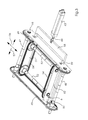
- einen Eckumsetzer in perspektivischer Ansicht,
- Figur 4
- einen Schnitt durch den Eckumsetzer in einer ersten Arbeitsposition,
- Figur 5
- einen Schnitt durch den Eckumsetzer in einer zweiten Arbeitsposition und
- Figur 6
- einen Schnitt durch den Eckumsetzer in einer dritten Arbeitsposition.
- Eine Bogen 7 verarbeitende Maschine, z. B. eine Druckmaschine 1, weist einen Anleger 2, mindestens ein Druckwerk 3 bzw. 4 und einen Ausleger 6 auf. Die Bogen 7 werden von einem Bogenstapel 8 entnommen und vereinzelt oder schuppenförmig über einen Zufiihrtisch 9 den Druckwerken 3 und 4 zugeführt. Diese enthalten in bekannter Weise jeweils einen Plattenzylinder 11, 12. Die Plattenzylinder 11 und 12 weisen jeweils eine Vorrichtung 13, 14 zum Befestigen flexibler Druckplatten auf. Darüber hinaus ist jedem Plattenzylinder 11, 12 eine Vorrichtung 16, 17 für den halb- oder vollautomatischen Druckplattenwechsel zugeordnet.
- Der Bogenstapel 8 liegt auf einer gesteuert anhebbaren Stapelplatte 10 auf. Die Entnahme der Bogen 7 erfolgt von der Oberseite des Bogenstapels 8 mittels eines so genannten Saugkopfes 18, der unter anderem eine Anzahl von Hub- und Schleppsaugern 19, 21 für die Vereinzelung der Bogen 7 aufweist. Darüber hinaus sind Blaseinrichtungen 22 zur Auflockerung der oberen Bogenlagen und Tastelemente 23 zur Stapelnachführung vorgesehen. Zur Ausrichtung des Bogenstapels 8, insbesondere der oberen Bogen 7 des Bogenstapels 8 sind eine Anzahl von seitlichen und hinteren Anschlägen 24 vorgesehen.
- Die Druckmaschine 1 weist ein Kettengreifersystem 26 zur Auslage von Bogen auf einen Auslegerstapel 27 auf.
-
Figur 2 zeigt eine Draufsicht auf die Druckmaschine 1 mit einem Logistiksystem 28 zum Transport von Paletten 29 und Bogenstapeln 27 auf Transportplatten 31. Die Transportplatten 31 werden ebenerdig in Transportbahnen 32 geführt und mittels Kettensystemen 34, 36 angetrieben, so dass eine Oberseite der Transportplatten 31 dasselbe Höhenniveau aufweist, wie die Oberfläche eines Hallenbodens 33, auf welchem die Druckmaschine 1 steht. - Das Kettensystem 34 ist quer zur Bogentransportrichtung der Druckmaschine 1 angeordnet. Das zweite Kettensystem 36 ist rechtwinklig zum ersten Kettensystem 34 angeordnet und kreuzt dieses im Bereich eines Eckumsetzers 37. Der Eckumsetzer 37 ist dazu ausgebildet eine Transportrichtung der Transportplatten 31 zu ändern. Durch die Anordnung gemäß
Figur 2 ist es möglich die Transportplatten 31 auf verschiedene Positionen zu verschieben. Die Positionen 38, 39, 41 sind Positionen für das Speichern bzw. für die Aufgabe oder Entnahme von Leerpaletten 29 oder Bogenstapeln 27. Auf der Position 42 ist der Eckumsetzer 37 angeordnet. An der Position 43 erfolgt die Aufnahme von Bogen der Bogen verarbeitenden Maschine 1 zur Bildung eines Bogenstapels 27. Die Position 44 dient als Warteposition für die Leerpalette 29. Selbstverständlich kann diese auf für die Entnahme von Bogenstapeln 27 benutzt werden. - Je nach Bedarf können weitere Speicherpositionen vorgesehen werden, wobei deren Anordnung unter dem Einsatz weiterer Eckumsetzer 37 beliebig ist. Selbstverständlich kann das Logistiksystem 28 auch einen Transportpfad zum Anleger 2 sowie zu nicht dargestellten Papierlagern aufweisen.
- Eine Bestückung des Auslegers 6 mit einer neuen Leerpalette 29 und Speicherung von Bogenstapeln 27 auf den Entnahmepositionen 38, 39, 41 erfolgt bei dem Logistiksystem 28 gemäß
Figur 2 folgendermaßen. - Die Position 38 des Logistiksystems 28 wird mit einer Leerpalette 29 bestückt und mittels des Kettensystems 34 auf die Warteposition 44 gefahren. Sobald der Bogenstapel 27 die vorgegebene Stapelhöhe erreicht hat, wird dieser im Bereich der Position 43 auf einer Transportplatte 31 des Logistiksystems 28 abgesetzt und auf die Position 38 verfahren. Weitere Bogenstapel 27 können auf den freien Speicherplätzen der Position 39, 41 zwischengelagert werden, bevor diese von einem Bediener entfernt werden müssen.
- Der Eckumsetzer 37 weist einen Rahmen 46 auf, in welchem eine Antriebswelle 47 und eine Umlenkwelle 48 gelagert sind, die zwei parallel angeordnete endlos umlaufende Transportbänder oder Ketten 49 antreiben.
- Ein zweiter Rahmen 51 ist innerhalb des Bauraumes des ersten Rahmens 46 angeordnet und weist ebenfalls eine im Rahmen 51 gelagerte Antriebswelle 52 und eine Umlenkwelle 53 auf, welche zwei parallel angeordnete endlos umlaufende Transportbänder oder Ketten 54 antreiben.
- Die Antriebsrichtung 56 (Pfeil in
Figur 3 ) der Fördermittel des ersten Rahmens 46 ist gegenüber der Antriebsrichtung 57 (PfeilFigur 3 ) der Fördermittel des zweiten Rahmens 51 um 90° versetzt angeordnet. - Die Rahmen 46, 51 sind auf einem verschiebbar angeordneten Steuerelement 58, z. B. einer Schaltkulisse, mittels Kurvenrollen 59,61 gelagert. Die Schaltkulisse 58 ist gabelförmig ausgebildet und umfasst den zweiten Rahmen 51, während sie durch Öffnungen des ersten Rahmens 46 hindurchgreift.
- Die Schaltkulisse 58 weist eine Steuerkontur 62 auf, die mit den Kurvenrollen 59 des ersten Rahmens 46 und den Kurvenrollen 51 des zweiten Rahmens in Kontakt steht. Ein stationär angeordneter Arbeitszylinder 63, z. B. Pneumatikzylinder, greift zur Höhenverstellung der Rahmen 46, 51 mit einer Kolbenstange 64 an der Schaltkulisse 58 an, um diese in bzw. gegen die Transportrichtung 57 zu verschieben.
- Der Kontakt der Kurvenrollen 59, 61 mit der Steuerkontur 62 der Schaltkulisse 58 bewirkt beim Verschieben der Steuerkulisse 58 ein Anheben des ersten Rahmens 46 auf ein vorgegebenes Höhenniveau und ein Absenken des zweiten Rahmens 51 auf ein darunterliegendes Niveau in der Warteposition und umgekehrt.
- Eine mittels der Fördermittel des ersten Rahmens 46 geförderte Transportplatte 31 wird gemäß
Figur 4 in der Position 42 gestoppt. Daraufhin wird die Schaltkulisse 58 betätigt, so dass die Fördermittel des zweiten Rahmens 51 auf das Höhenniveau der Fördermittel des ersten Rahmens 46 gemäßFigur 5 angehoben werden. - Durch ein weiteres Betätigen der Schaltkulisse 58 wird der erste Rahmen 46 gemäß
Figur 6 abgesenkt. Durch Anfahren der Fördermittel des zweiten Rahmens 51 wird die Transportplatte 31 auf die Position 39 oder wahlweise 41 verschoben. -
- 1
- Druckmaschine
- 2
- Anleger
- 3
- Druckwerk
- 4
- Druckwerk
- 5
- ./.
- 6
- Ausleger
- 7
- Bogen
- 8
- Bogenstapel
- 9
- Zufiihrtisch
- 10
- Stapelplatte
- 11
- Plattenzylinder
- 12
- Plattenzylinder
- 13
- Druckplattenbefestigung
- 14
- Druckplattenbefestigung
- 15
- ./.
- 16
- Druckplattenwechsler
- 17
- Druckplattenwechsler
- 18
- Saugkopf
- 19
- Hubsauger
- 20
- ./.
- 21
- Schleppsauger
- 22
- Blaseinrichtung
- 23
- Tastelement
- 24
- Anschlag
- 25
- ./.
- 26
- Kettengreifersystem
- 27
- Auslegerstapel
- 28
- Logistiksystem
- 29
- Palette
- 30
- ./.
- 31
- Transportplatte
- 32
- Transportbahn
- 33
- Hallenboden
- 34
- Kettensystem
- 35
- ./.
- 36
- Kettensystem
- 37
- Eckumsetzer
- 38
- Position
- 39
- Position
- 40
- ./.
- 41
- Position
- 42
- Position
- 43
- Position
- 44
- Position
- 45
- ./.
- 46
- erster Rahmen (37)
- 47
- Antriebswelle
- 48
- Umlenkwelle
- 49
- Ketten / Transportbänder
- 50
- ./.
- 51
- zweiter Rahmen (37)
- 52
- Antriebswelle
- 53
- Umlenkwelle
- 54
- Ketten / Transportbänder
- 55
- ./.
- 56
- Pfeil Antriebsrichtung (46)
- 57
- Pfeil Antriebsrichtung (51)
- 58
- Steuerelement
- 59
- Kurvenrolle (46)
- 60
- ./.
- 61
- Kurvenrolle (51)
- 62
- Steuerkontur (58)
- 63
- Arbeitszylinder
- 64
- Kolbenstange (63)
Claims (10)
- Logistiksystem für eine Bogen verarbeitende Maschine, mit einer Transportbahn für Paletten und Bogenstapel, welche Speicherplätze zum Zwischenspeichern der Paletten und Bogenstapel sowie mindestens einen Eckumsetzer zum Ändern der Transportrichtung aufweist,
dadurch gekennzeichnet,
dass der Eckumsetzer (37) zwei höhenverlagerbar angeordnete Fördermittel (49, 54) aufweist, welche rechtwinklig zueinander angeordnet sind. - Logistiksystem nach Anspruch 1,
dadurch gekennzeichnet,
dass das Logistiksystem (28) verschiebbare Transportplatten (31) aufweist, die die Transportbahnen (32) ebenerdig, auf dem Niveau eines Hallenbodens (33) abdecken. - Logistiksystem nach Anspruch 2,
dadurch gekennzeichnet,
dass zum Verschieben der Transportplatten (31) Kettensysteme (34, 36) vorgesehen sind. - Logistiksystem nach Anspruch 1,
dadurch gekennzeichnet,
dass die Fördermittel (49; 54) jeweils parallel angeordnete endlos umlaufende antreibbare Transportbänder oder Ketten sind. - Logistiksystem nach Anspruch 1,
dadurch gekennzeichnet,
dass die Fördermittel (49; 54) jeweils in einem Rahmen (46, 51) gelagert sind. - Logistiksystem nach Anspruch 5,
dadurch gekennzeichnet,
dass die Rahmen (46, 51) jeweils mit einem Steuerelement (58) in Verbindung stehen. - Logistiksystem nach Anspruch 6,
dadurch gekennzeichnet,
dass das Steuerelement (58) als horizontal verschiebbar gelagerte eine Steuerkontur (62) aufweisende Schaltkulisse ausgebildet ist. - Logistiksystem nach Anspruch 7,
dadurch gekennzeichnet,
dass die Steuerkontur (62) der Schaltkulisse (58) mit Anschlägen (59, 61) zusammenwirkt, welche an dem Rahmen (46, 51) angeordnet sind. - Logistiksystem nach Anspruch 8,
dadurch gekennzeichnet,
dass die Anschläge (59, 61) als drehbar gelagerte Kurvenrollen ausgebildet sind. - Logistiksystem nach Anspruch 9,
dadurch gekennzeichnet,
dass ein einziger stationär angeordneter Arbeitszylinder (63) zur Erzeugung der Horizontalbewegung des Steuerelementes (58) vorgesehen ist.
Applications Claiming Priority (1)
| Application Number | Priority Date | Filing Date | Title |
|---|---|---|---|
| DE102010012105A DE102010012105A1 (de) | 2010-03-19 | 2010-03-19 | Logistiksystem für eine Bogenverarbeitende Maschine |
Publications (3)
| Publication Number | Publication Date |
|---|---|
| EP2366642A2 true EP2366642A2 (de) | 2011-09-21 |
| EP2366642A3 EP2366642A3 (de) | 2015-07-22 |
| EP2366642B1 EP2366642B1 (de) | 2016-10-12 |
Family
ID=44121478
Family Applications (1)
| Application Number | Title | Priority Date | Filing Date |
|---|---|---|---|
| EP11154767.5A Not-in-force EP2366642B1 (de) | 2010-03-19 | 2011-02-17 | Logistiksystem für eine Bogenverarbeitende Maschine |
Country Status (3)
| Country | Link |
|---|---|
| US (1) | US8590691B2 (de) |
| EP (1) | EP2366642B1 (de) |
| DE (1) | DE102010012105A1 (de) |
Cited By (4)
| Publication number | Priority date | Publication date | Assignee | Title |
|---|---|---|---|---|
| CN104477635A (zh) * | 2014-12-16 | 2015-04-01 | 湖州锐格物流科技有限公司 | 一种高速分流机 |
| CN105173665A (zh) * | 2015-07-13 | 2015-12-23 | 苏州优备精密电子有限公司 | 自动分流输送装置 |
| CN105923363A (zh) * | 2016-06-15 | 2016-09-07 | 广东正业科技股份有限公司 | 一种用于电池的生产系统及传送设备 |
| CN110745516A (zh) * | 2019-10-30 | 2020-02-04 | 苏州精濑光电有限公司 | 一种传输方法 |
Families Citing this family (6)
| Publication number | Priority date | Publication date | Assignee | Title |
|---|---|---|---|---|
| US8776983B2 (en) * | 2012-06-26 | 2014-07-15 | Shenzhen China Star Optoelectronics Technology Co., Ltd | Turntable device for substrate and substrate transporting system |
| KR20140037341A (ko) * | 2012-09-17 | 2014-03-27 | 한국전자통신연구원 | 4방향 크로스벨트 및 4방향 크로스벨트를 이용한 자동화 분류 장치 그리고 분류 방법 |
| US9745137B1 (en) * | 2016-06-03 | 2017-08-29 | Zme, Llc | Apparatus, system and method for material handling and/or processing |
| WO2019244562A1 (ja) * | 2018-06-19 | 2019-12-26 | 日本電産シンポ株式会社 | 搬送車 |
| WO2023242806A2 (en) * | 2022-06-15 | 2023-12-21 | Dematic Corp. | Motor driven roller transmission system for conveyance system |
| DE102023116835A1 (de) | 2022-07-25 | 2024-01-25 | Heidelberger Druckmaschinen Aktiengesellschaft | Falzmaschine mit einem Anleger für Bogenstapel und ein System aus einer Falzmaschine und einem Flurförderfahrzeug |
Family Cites Families (16)
| Publication number | Priority date | Publication date | Assignee | Title |
|---|---|---|---|---|
| DE1808023A1 (de) * | 1968-11-09 | 1970-05-27 | Knaust Dr Ing Herbert | Waagerechter Umlauffoerderer |
| DE7622026U1 (de) * | 1976-07-13 | 1984-11-22 | Lager- u. Fördertechnik, 7320 Göppingen | Fahrbare transportbuehne fuer die beschickung von rollentraegern an rotations-druckmaschinen |
| DD201291B1 (de) * | 1981-12-08 | 1987-01-21 | Guenter Schoelzel | Unterflurtransporteinrichtung fuer kabeltrommeln |
| JPS60118520A (ja) * | 1983-11-30 | 1985-06-26 | Natl House Ind Co Ltd | ワ−ク取出し装置 |
| JPH0738260Y2 (ja) * | 1988-08-25 | 1995-08-30 | 第一工業株式会社 | コンベヤによる物品仕分装置 |
| US4931131A (en) * | 1989-06-02 | 1990-06-05 | Thompson Ralph F | Package collator machine |
| US5551550A (en) * | 1994-08-18 | 1996-09-03 | Planet Products Corporation | Article accumulator for use with a robotic hand |
| KR100290152B1 (ko) * | 1997-11-14 | 2001-10-24 | 윤종용 | 제품생산시스템 |
| DE19919593A1 (de) * | 1999-02-12 | 2000-08-31 | Thiessen Papchem Gmbh & Co Kg | Transportvorrichtung |
| US6347540B1 (en) * | 1999-03-31 | 2002-02-19 | Debiasi International Limited | Robot-actuate transfer assembly |
| DE20107828U1 (de) | 2000-05-10 | 2001-12-20 | MAN Roland Druckmaschinen AG, 63075 Offenbach | Stapelkontrollstation und Datensystem in einer Logistik für Druckerein |
| GB0020950D0 (en) * | 2000-08-24 | 2000-10-11 | Hazmac Handling Ltd | Article transferring device |
| DE10315403A1 (de) * | 2003-04-04 | 2004-10-21 | Siemens Ag | Fördersystem, insbesondere eine Flughafen-Gepäckförderanlage, für Behälter |
| DE102006002356B4 (de) * | 2005-02-21 | 2021-05-06 | Heidelberger Druckmaschinen Ag | Verfahren und Vorrichtung zur Absicherung von Gefahrbereichen in Bogendruckmaschinen |
| DE102008007613A1 (de) | 2008-02-04 | 2009-08-06 | Heidelberger Druckmaschinen Ag | Vorrichtung zum Transport einer Palette |
| JP5247606B2 (ja) * | 2009-06-23 | 2013-07-24 | 伊東電機株式会社 | 移載装置 |
-
2010
- 2010-03-19 DE DE102010012105A patent/DE102010012105A1/de not_active Withdrawn
-
2011
- 2011-02-17 EP EP11154767.5A patent/EP2366642B1/de not_active Not-in-force
- 2011-03-21 US US13/052,419 patent/US8590691B2/en not_active Expired - Fee Related
Non-Patent Citations (1)
| Title |
|---|
| None |
Cited By (6)
| Publication number | Priority date | Publication date | Assignee | Title |
|---|---|---|---|---|
| CN104477635A (zh) * | 2014-12-16 | 2015-04-01 | 湖州锐格物流科技有限公司 | 一种高速分流机 |
| CN104477635B (zh) * | 2014-12-16 | 2016-07-06 | 湖州锐格物流科技有限公司 | 一种高速分流机 |
| CN105173665A (zh) * | 2015-07-13 | 2015-12-23 | 苏州优备精密电子有限公司 | 自动分流输送装置 |
| CN105173665B (zh) * | 2015-07-13 | 2017-11-24 | 苏州优备精密智能装备股份有限公司 | 自动分流输送装置 |
| CN105923363A (zh) * | 2016-06-15 | 2016-09-07 | 广东正业科技股份有限公司 | 一种用于电池的生产系统及传送设备 |
| CN110745516A (zh) * | 2019-10-30 | 2020-02-04 | 苏州精濑光电有限公司 | 一种传输方法 |
Also Published As
| Publication number | Publication date |
|---|---|
| US8590691B2 (en) | 2013-11-26 |
| US20110226585A1 (en) | 2011-09-22 |
| EP2366642B1 (de) | 2016-10-12 |
| DE102010012105A1 (de) | 2011-09-22 |
| EP2366642A3 (de) | 2015-07-22 |
Similar Documents
| Publication | Publication Date | Title |
|---|---|---|
| EP2366642B1 (de) | Logistiksystem für eine Bogenverarbeitende Maschine | |
| DE4131015C2 (de) | Bogenausleger | |
| EP0548519A1 (de) | Verfahren zum Be- und Entladen von Paletten mit Stapeln von flächigen Produkten nd Vorrichtung zur Durchführung des Verfahrens | |
| EP0377398A1 (de) | Palettierroboter | |
| EP2085336B1 (de) | Vorrichtung zum Transport einer Palette | |
| DE10356563A1 (de) | Vorrichtung zum Palettieren von Kartonagen mit Aufnahmestation mit Seiteneinführung | |
| DE102019125807B3 (de) | Auslage mit einer Stapeltragvorrichtung zur Aufnahme eines Stapels aus Bogen | |
| DE10122428A1 (de) | Ausrichtstation in einer Logistik für Druckereien | |
| DE4118640A1 (de) | Vorrichtung zum beladen von paletten mit kartons | |
| DE4023877A1 (de) | Bogen verarbeitende maschine und damit zusammenarbeitende transporteinrichtung fuer bogenstapel | |
| DE102022118978A1 (de) | Auslage und Verfahren zum Betreiben einer Auslage mit einem von einem Stapelhubantrieb vertikal verlagerbaren Stapelträger | |
| DE102004062735B4 (de) | Vorrichtung zum Ausrichten von Bogen, die auf einem Bogenstapel abgelegt werden | |
| DE102022118979A1 (de) | Auslage und Verfahren zum Betreiben einer Auslage mit einem von einem Stapelhubantrieb vertikal verlagerbaren Stapelträger | |
| DE102022118506A1 (de) | Verfahren zum Herstellen von gedruckten und gefalzten Produkten und System aus einer Druckmaschine, einer Falzmaschine und einem fahrerlosen Transportfahrzeug | |
| EP1611039A1 (de) | Transporteinrichtung, insbesondere für plattenförmige werkstücke | |
| DE102020207420A1 (de) | Vorrichtung zur Druckplatten-Handhabung an einer Druckmaschine | |
| DE102006038089B4 (de) | Kistenstapler | |
| DE3033682C2 (de) | Vorrichtung zum Be- und/oder Entladen aus übereinandergestapelter Wandanordnung in lineare Transportanordnung | |
| DE9317228U1 (de) | Vorrichtung zum Handhaben von Leiterplatten | |
| DE102023116835A1 (de) | Falzmaschine mit einem Anleger für Bogenstapel und ein System aus einer Falzmaschine und einem Flurförderfahrzeug | |
| DE4013172C2 (de) | Vorrichtung zum Zu- und Abführen von Paletten an Bogenanlegern | |
| DE4138488C2 (de) | Vorrichtung zum automatischen Stapelwechsel im Ausleger einer Druckmaschine | |
| DE102019207472A1 (de) | Einrichtung zum Transportieren von Paletten für Bogen aus Bedruckstoff | |
| DE19516582C2 (de) | Vorrichtung zur Vereinigung eines Restbogenstapels mit einem Hauptbogenstapel | |
| DE19749193C2 (de) | Vorrichtung zum automatischen Handhaben von Paletten |
Legal Events
| Date | Code | Title | Description |
|---|---|---|---|
| PUAI | Public reference made under article 153(3) epc to a published international application that has entered the european phase |
Free format text: ORIGINAL CODE: 0009012 |
|
| AK | Designated contracting states |
Kind code of ref document: A2 Designated state(s): AL AT BE BG CH CY CZ DE DK EE ES FI FR GB GR HR HU IE IS IT LI LT LU LV MC MK MT NL NO PL PT RO RS SE SI SK SM TR |
|
| AX | Request for extension of the european patent |
Extension state: BA ME |
|
| PUAL | Search report despatched |
Free format text: ORIGINAL CODE: 0009013 |
|
| AK | Designated contracting states |
Kind code of ref document: A3 Designated state(s): AL AT BE BG CH CY CZ DE DK EE ES FI FR GB GR HR HU IE IS IT LI LT LU LV MC MK MT NL NO PL PT RO RS SE SI SK SM TR |
|
| AX | Request for extension of the european patent |
Extension state: BA ME |
|
| RIC1 | Information provided on ipc code assigned before grant |
Ipc: B65G 47/53 20060101AFI20150615BHEP |
|
| 17P | Request for examination filed |
Effective date: 20160122 |
|
| RBV | Designated contracting states (corrected) |
Designated state(s): AL AT BE BG CH CY CZ DE DK EE ES FI FR GB GR HR HU IE IS IT LI LT LU LV MC MK MT NL NO PL PT RO RS SE SI SK SM TR |
|
| GRAP | Despatch of communication of intention to grant a patent |
Free format text: ORIGINAL CODE: EPIDOSNIGR1 |
|
| INTG | Intention to grant announced |
Effective date: 20160520 |
|
| GRAS | Grant fee paid |
Free format text: ORIGINAL CODE: EPIDOSNIGR3 |
|
| GRAA | (expected) grant |
Free format text: ORIGINAL CODE: 0009210 |
|
| AK | Designated contracting states |
Kind code of ref document: B1 Designated state(s): AL AT BE BG CH CY CZ DE DK EE ES FI FR GB GR HR HU IE IS IT LI LT LU LV MC MK MT NL NO PL PT RO RS SE SI SK SM TR |
|
| REG | Reference to a national code |
Ref country code: GB Ref legal event code: FG4D Free format text: NOT ENGLISH |
|
| REG | Reference to a national code |
Ref country code: CH Ref legal event code: EP |
|
| REG | Reference to a national code |
Ref country code: AT Ref legal event code: REF Ref document number: 836294 Country of ref document: AT Kind code of ref document: T Effective date: 20161015 |
|
| REG | Reference to a national code |
Ref country code: IE Ref legal event code: FG4D Free format text: LANGUAGE OF EP DOCUMENT: GERMAN |
|
| REG | Reference to a national code |
Ref country code: DE Ref legal event code: R096 Ref document number: 502011010879 Country of ref document: DE |
|
| REG | Reference to a national code |
Ref country code: LT Ref legal event code: MG4D |
|
| REG | Reference to a national code |
Ref country code: NL Ref legal event code: MP Effective date: 20161012 |
|
| PG25 | Lapsed in a contracting state [announced via postgrant information from national office to epo] |
Ref country code: LV Free format text: LAPSE BECAUSE OF FAILURE TO SUBMIT A TRANSLATION OF THE DESCRIPTION OR TO PAY THE FEE WITHIN THE PRESCRIBED TIME-LIMIT Effective date: 20161012 |
|
| PG25 | Lapsed in a contracting state [announced via postgrant information from national office to epo] |
Ref country code: NO Free format text: LAPSE BECAUSE OF FAILURE TO SUBMIT A TRANSLATION OF THE DESCRIPTION OR TO PAY THE FEE WITHIN THE PRESCRIBED TIME-LIMIT Effective date: 20170112 Ref country code: LT Free format text: LAPSE BECAUSE OF FAILURE TO SUBMIT A TRANSLATION OF THE DESCRIPTION OR TO PAY THE FEE WITHIN THE PRESCRIBED TIME-LIMIT Effective date: 20161012 Ref country code: SE Free format text: LAPSE BECAUSE OF FAILURE TO SUBMIT A TRANSLATION OF THE DESCRIPTION OR TO PAY THE FEE WITHIN THE PRESCRIBED TIME-LIMIT Effective date: 20161012 Ref country code: GR Free format text: LAPSE BECAUSE OF FAILURE TO SUBMIT A TRANSLATION OF THE DESCRIPTION OR TO PAY THE FEE WITHIN THE PRESCRIBED TIME-LIMIT Effective date: 20170113 |
|
| PG25 | Lapsed in a contracting state [announced via postgrant information from national office to epo] |
Ref country code: ES Free format text: LAPSE BECAUSE OF FAILURE TO SUBMIT A TRANSLATION OF THE DESCRIPTION OR TO PAY THE FEE WITHIN THE PRESCRIBED TIME-LIMIT Effective date: 20161012 Ref country code: HR Free format text: LAPSE BECAUSE OF FAILURE TO SUBMIT A TRANSLATION OF THE DESCRIPTION OR TO PAY THE FEE WITHIN THE PRESCRIBED TIME-LIMIT Effective date: 20161012 Ref country code: PT Free format text: LAPSE BECAUSE OF FAILURE TO SUBMIT A TRANSLATION OF THE DESCRIPTION OR TO PAY THE FEE WITHIN THE PRESCRIBED TIME-LIMIT Effective date: 20170213 Ref country code: NL Free format text: LAPSE BECAUSE OF FAILURE TO SUBMIT A TRANSLATION OF THE DESCRIPTION OR TO PAY THE FEE WITHIN THE PRESCRIBED TIME-LIMIT Effective date: 20161012 Ref country code: FI Free format text: LAPSE BECAUSE OF FAILURE TO SUBMIT A TRANSLATION OF THE DESCRIPTION OR TO PAY THE FEE WITHIN THE PRESCRIBED TIME-LIMIT Effective date: 20161012 Ref country code: BE Free format text: LAPSE BECAUSE OF NON-PAYMENT OF DUE FEES Effective date: 20170228 Ref country code: PL Free format text: LAPSE BECAUSE OF FAILURE TO SUBMIT A TRANSLATION OF THE DESCRIPTION OR TO PAY THE FEE WITHIN THE PRESCRIBED TIME-LIMIT Effective date: 20161012 Ref country code: IS Free format text: LAPSE BECAUSE OF FAILURE TO SUBMIT A TRANSLATION OF THE DESCRIPTION OR TO PAY THE FEE WITHIN THE PRESCRIBED TIME-LIMIT Effective date: 20170212 Ref country code: RS Free format text: LAPSE BECAUSE OF FAILURE TO SUBMIT A TRANSLATION OF THE DESCRIPTION OR TO PAY THE FEE WITHIN THE PRESCRIBED TIME-LIMIT Effective date: 20161012 |
|
| REG | Reference to a national code |
Ref country code: DE Ref legal event code: R097 Ref document number: 502011010879 Country of ref document: DE |
|
| PG25 | Lapsed in a contracting state [announced via postgrant information from national office to epo] |
Ref country code: RO Free format text: LAPSE BECAUSE OF FAILURE TO SUBMIT A TRANSLATION OF THE DESCRIPTION OR TO PAY THE FEE WITHIN THE PRESCRIBED TIME-LIMIT Effective date: 20161012 Ref country code: CZ Free format text: LAPSE BECAUSE OF FAILURE TO SUBMIT A TRANSLATION OF THE DESCRIPTION OR TO PAY THE FEE WITHIN THE PRESCRIBED TIME-LIMIT Effective date: 20161012 Ref country code: DK Free format text: LAPSE BECAUSE OF FAILURE TO SUBMIT A TRANSLATION OF THE DESCRIPTION OR TO PAY THE FEE WITHIN THE PRESCRIBED TIME-LIMIT Effective date: 20161012 Ref country code: EE Free format text: LAPSE BECAUSE OF FAILURE TO SUBMIT A TRANSLATION OF THE DESCRIPTION OR TO PAY THE FEE WITHIN THE PRESCRIBED TIME-LIMIT Effective date: 20161012 Ref country code: SK Free format text: LAPSE BECAUSE OF FAILURE TO SUBMIT A TRANSLATION OF THE DESCRIPTION OR TO PAY THE FEE WITHIN THE PRESCRIBED TIME-LIMIT Effective date: 20161012 |
|
| PLBE | No opposition filed within time limit |
Free format text: ORIGINAL CODE: 0009261 |
|
| STAA | Information on the status of an ep patent application or granted ep patent |
Free format text: STATUS: NO OPPOSITION FILED WITHIN TIME LIMIT |
|
| PG25 | Lapsed in a contracting state [announced via postgrant information from national office to epo] |
Ref country code: IT Free format text: LAPSE BECAUSE OF FAILURE TO SUBMIT A TRANSLATION OF THE DESCRIPTION OR TO PAY THE FEE WITHIN THE PRESCRIBED TIME-LIMIT Effective date: 20161012 Ref country code: BG Free format text: LAPSE BECAUSE OF FAILURE TO SUBMIT A TRANSLATION OF THE DESCRIPTION OR TO PAY THE FEE WITHIN THE PRESCRIBED TIME-LIMIT Effective date: 20170112 Ref country code: SM Free format text: LAPSE BECAUSE OF FAILURE TO SUBMIT A TRANSLATION OF THE DESCRIPTION OR TO PAY THE FEE WITHIN THE PRESCRIBED TIME-LIMIT Effective date: 20161012 |
|
| 26N | No opposition filed |
Effective date: 20170713 |
|
| PG25 | Lapsed in a contracting state [announced via postgrant information from national office to epo] |
Ref country code: MC Free format text: LAPSE BECAUSE OF FAILURE TO SUBMIT A TRANSLATION OF THE DESCRIPTION OR TO PAY THE FEE WITHIN THE PRESCRIBED TIME-LIMIT Effective date: 20161012 |
|
| REG | Reference to a national code |
Ref country code: CH Ref legal event code: PL |
|
| GBPC | Gb: european patent ceased through non-payment of renewal fee |
Effective date: 20170217 |
|
| PG25 | Lapsed in a contracting state [announced via postgrant information from national office to epo] |
Ref country code: CH Free format text: LAPSE BECAUSE OF NON-PAYMENT OF DUE FEES Effective date: 20170228 Ref country code: LI Free format text: LAPSE BECAUSE OF NON-PAYMENT OF DUE FEES Effective date: 20170228 |
|
| REG | Reference to a national code |
Ref country code: IE Ref legal event code: MM4A |
|
| PG25 | Lapsed in a contracting state [announced via postgrant information from national office to epo] |
Ref country code: SI Free format text: LAPSE BECAUSE OF FAILURE TO SUBMIT A TRANSLATION OF THE DESCRIPTION OR TO PAY THE FEE WITHIN THE PRESCRIBED TIME-LIMIT Effective date: 20161012 |
|
| REG | Reference to a national code |
Ref country code: FR Ref legal event code: ST Effective date: 20171031 |
|
| PG25 | Lapsed in a contracting state [announced via postgrant information from national office to epo] |
Ref country code: LU Free format text: LAPSE BECAUSE OF NON-PAYMENT OF DUE FEES Effective date: 20170217 |
|
| PG25 | Lapsed in a contracting state [announced via postgrant information from national office to epo] |
Ref country code: FR Free format text: LAPSE BECAUSE OF NON-PAYMENT OF DUE FEES Effective date: 20170228 |
|
| REG | Reference to a national code |
Ref country code: BE Ref legal event code: MM Effective date: 20170228 |
|
| PG25 | Lapsed in a contracting state [announced via postgrant information from national office to epo] |
Ref country code: IE Free format text: LAPSE BECAUSE OF NON-PAYMENT OF DUE FEES Effective date: 20170217 Ref country code: GB Free format text: LAPSE BECAUSE OF NON-PAYMENT OF DUE FEES Effective date: 20170217 |
|
| REG | Reference to a national code |
Ref country code: AT Ref legal event code: MM01 Ref document number: 836294 Country of ref document: AT Kind code of ref document: T Effective date: 20170217 |
|
| PG25 | Lapsed in a contracting state [announced via postgrant information from national office to epo] |
Ref country code: AT Free format text: LAPSE BECAUSE OF NON-PAYMENT OF DUE FEES Effective date: 20170217 |
|
| PG25 | Lapsed in a contracting state [announced via postgrant information from national office to epo] |
Ref country code: MT Free format text: LAPSE BECAUSE OF FAILURE TO SUBMIT A TRANSLATION OF THE DESCRIPTION OR TO PAY THE FEE WITHIN THE PRESCRIBED TIME-LIMIT Effective date: 20161012 |
|
| PG25 | Lapsed in a contracting state [announced via postgrant information from national office to epo] |
Ref country code: HU Free format text: LAPSE BECAUSE OF FAILURE TO SUBMIT A TRANSLATION OF THE DESCRIPTION OR TO PAY THE FEE WITHIN THE PRESCRIBED TIME-LIMIT; INVALID AB INITIO Effective date: 20110217 |
|
| PG25 | Lapsed in a contracting state [announced via postgrant information from national office to epo] |
Ref country code: CY Free format text: LAPSE BECAUSE OF NON-PAYMENT OF DUE FEES Effective date: 20161012 |
|
| PG25 | Lapsed in a contracting state [announced via postgrant information from national office to epo] |
Ref country code: MK Free format text: LAPSE BECAUSE OF FAILURE TO SUBMIT A TRANSLATION OF THE DESCRIPTION OR TO PAY THE FEE WITHIN THE PRESCRIBED TIME-LIMIT Effective date: 20161012 |
|
| PG25 | Lapsed in a contracting state [announced via postgrant information from national office to epo] |
Ref country code: TR Free format text: LAPSE BECAUSE OF FAILURE TO SUBMIT A TRANSLATION OF THE DESCRIPTION OR TO PAY THE FEE WITHIN THE PRESCRIBED TIME-LIMIT Effective date: 20161012 |
|
| PG25 | Lapsed in a contracting state [announced via postgrant information from national office to epo] |
Ref country code: AL Free format text: LAPSE BECAUSE OF FAILURE TO SUBMIT A TRANSLATION OF THE DESCRIPTION OR TO PAY THE FEE WITHIN THE PRESCRIBED TIME-LIMIT Effective date: 20161012 |
|
| PGFP | Annual fee paid to national office [announced via postgrant information from national office to epo] |
Ref country code: DE Payment date: 20210228 Year of fee payment: 11 |
|
| REG | Reference to a national code |
Ref country code: DE Ref legal event code: R119 Ref document number: 502011010879 Country of ref document: DE |
|
| PG25 | Lapsed in a contracting state [announced via postgrant information from national office to epo] |
Ref country code: DE Free format text: LAPSE BECAUSE OF NON-PAYMENT OF DUE FEES Effective date: 20220901 |