EP2366477A1 - Tête à aléser - Google Patents
Tête à aléser Download PDFInfo
- Publication number
- EP2366477A1 EP2366477A1 EP11405211A EP11405211A EP2366477A1 EP 2366477 A1 EP2366477 A1 EP 2366477A1 EP 11405211 A EP11405211 A EP 11405211A EP 11405211 A EP11405211 A EP 11405211A EP 2366477 A1 EP2366477 A1 EP 2366477A1
- Authority
- EP
- European Patent Office
- Prior art keywords
- boring head
- tool body
- clamping surface
- head according
- clamping
- Prior art date
- Legal status (The legal status is an assumption and is not a legal conclusion. Google has not performed a legal analysis and makes no representation as to the accuracy of the status listed.)
- Granted
Links
- 239000000969 carrier Substances 0.000 claims description 24
- 239000012267 brine Substances 0.000 description 6
- HPALAKNZSZLMCH-UHFFFAOYSA-M sodium;chloride;hydrate Chemical compound O.[Na+].[Cl-] HPALAKNZSZLMCH-UHFFFAOYSA-M 0.000 description 6
- 238000007792 addition Methods 0.000 description 3
- 238000006073 displacement reaction Methods 0.000 description 3
- 238000005553 drilling Methods 0.000 description 3
- 239000000463 material Substances 0.000 description 3
- 239000007787 solid Substances 0.000 description 2
- 230000005540 biological transmission Effects 0.000 description 1
- 230000001419 dependent effect Effects 0.000 description 1
Images


Classifications
-
- B—PERFORMING OPERATIONS; TRANSPORTING
- B23—MACHINE TOOLS; METAL-WORKING NOT OTHERWISE PROVIDED FOR
- B23B—TURNING; BORING
- B23B29/00—Holders for non-rotary cutting tools; Boring bars or boring heads; Accessories for tool holders
- B23B29/03—Boring heads
-
- B—PERFORMING OPERATIONS; TRANSPORTING
- B23—MACHINE TOOLS; METAL-WORKING NOT OTHERWISE PROVIDED FOR
- B23B—TURNING; BORING
- B23B29/00—Holders for non-rotary cutting tools; Boring bars or boring heads; Accessories for tool holders
- B23B29/03—Boring heads
- B23B29/034—Boring heads with tools moving radially, e.g. for making chamfers or undercuttings
- B23B29/03403—Boring heads with tools moving radially, e.g. for making chamfers or undercuttings radially adjustable before starting manufacturing
- B23B29/03407—Boring heads with tools moving radially, e.g. for making chamfers or undercuttings radially adjustable before starting manufacturing by means of screws and nuts
-
- B—PERFORMING OPERATIONS; TRANSPORTING
- B23—MACHINE TOOLS; METAL-WORKING NOT OTHERWISE PROVIDED FOR
- B23B—TURNING; BORING
- B23B29/00—Holders for non-rotary cutting tools; Boring bars or boring heads; Accessories for tool holders
- B23B29/04—Tool holders for a single cutting tool
- B23B29/12—Special arrangements on tool holders
-
- B—PERFORMING OPERATIONS; TRANSPORTING
- B23—MACHINE TOOLS; METAL-WORKING NOT OTHERWISE PROVIDED FOR
- B23B—TURNING; BORING
- B23B2229/00—Details of boring bars or boring heads
- B23B2229/08—Cutting edges of different lengths or at different axial positions
-
- B—PERFORMING OPERATIONS; TRANSPORTING
- B23—MACHINE TOOLS; METAL-WORKING NOT OTHERWISE PROVIDED FOR
- B23B—TURNING; BORING
- B23B2229/00—Details of boring bars or boring heads
- B23B2229/12—Cutting inserts located on different radii
-
- Y—GENERAL TAGGING OF NEW TECHNOLOGICAL DEVELOPMENTS; GENERAL TAGGING OF CROSS-SECTIONAL TECHNOLOGIES SPANNING OVER SEVERAL SECTIONS OF THE IPC; TECHNICAL SUBJECTS COVERED BY FORMER USPC CROSS-REFERENCE ART COLLECTIONS [XRACs] AND DIGESTS
- Y10—TECHNICAL SUBJECTS COVERED BY FORMER USPC
- Y10T—TECHNICAL SUBJECTS COVERED BY FORMER US CLASSIFICATION
- Y10T408/00—Cutting by use of rotating axially moving tool
- Y10T408/83—Tool-support with means to move Tool relative to tool-support
- Y10T408/85—Tool-support with means to move Tool relative to tool-support to move radially
- Y10T408/858—Moving means including wedge, screw or cam
- Y10T408/8598—Screw extending perpendicular to tool-axis
-
- Y—GENERAL TAGGING OF NEW TECHNOLOGICAL DEVELOPMENTS; GENERAL TAGGING OF CROSS-SECTIONAL TECHNOLOGIES SPANNING OVER SEVERAL SECTIONS OF THE IPC; TECHNICAL SUBJECTS COVERED BY FORMER USPC CROSS-REFERENCE ART COLLECTIONS [XRACs] AND DIGESTS
- Y10—TECHNICAL SUBJECTS COVERED BY FORMER USPC
- Y10T—TECHNICAL SUBJECTS COVERED BY FORMER US CLASSIFICATION
- Y10T408/00—Cutting by use of rotating axially moving tool
- Y10T408/86—Tool-support with means to permit positioning of the Tool relative to support
- Y10T408/87—Tool having stepped cutting edges
-
- Y—GENERAL TAGGING OF NEW TECHNOLOGICAL DEVELOPMENTS; GENERAL TAGGING OF CROSS-SECTIONAL TECHNOLOGIES SPANNING OVER SEVERAL SECTIONS OF THE IPC; TECHNICAL SUBJECTS COVERED BY FORMER USPC CROSS-REFERENCE ART COLLECTIONS [XRACs] AND DIGESTS
- Y10—TECHNICAL SUBJECTS COVERED BY FORMER USPC
- Y10T—TECHNICAL SUBJECTS COVERED BY FORMER US CLASSIFICATION
- Y10T408/00—Cutting by use of rotating axially moving tool
- Y10T408/86—Tool-support with means to permit positioning of the Tool relative to support
- Y10T408/885—Tool-support with means to permit positioning of the Tool relative to support including tool-holding clamp and clamp actuator
-
- Y—GENERAL TAGGING OF NEW TECHNOLOGICAL DEVELOPMENTS; GENERAL TAGGING OF CROSS-SECTIONAL TECHNOLOGIES SPANNING OVER SEVERAL SECTIONS OF THE IPC; TECHNICAL SUBJECTS COVERED BY FORMER USPC CROSS-REFERENCE ART COLLECTIONS [XRACs] AND DIGESTS
- Y10—TECHNICAL SUBJECTS COVERED BY FORMER USPC
- Y10T—TECHNICAL SUBJECTS COVERED BY FORMER US CLASSIFICATION
- Y10T408/00—Cutting by use of rotating axially moving tool
- Y10T408/89—Tool or Tool with support
- Y10T408/905—Having stepped cutting edges
- Y10T408/906—Axially spaced
Definitions
- the invention relates to a boring head with a tool body and two detachably mounted on this and 180 ° to each other twisted arranged cutting carriers, which are mounted for radial displacement of the cutting on a clamping surface slidably, with clamping means for clamping the blade carrier against the clamping surface and with adjusting means for radial Adjusting the blade carrier.
- Boring heads of this type have long been known in the art. It is here for example on the EP-B-0 990 477 . CH 627 676 and CH 611 190 directed. Such double-edged boring heads are particularly suitable for roughing bores.
- the two cutting edges which are rotated by 180 ° with respect to each other, allow a double feed rate compared to single-edged tools. Basically, three types of roughing are possible. In double-offset roughing, the cutting edges are offset axially and radially. In rotationally symmetrical roughing, the two cutting edges are neither axially nor radially offset from each other. This is the most commonly used setting. In full-profile roughing, the two cutting edges are greatly offset in diameter.
- the invention is based on the object zuffe a boring head of the type mentioned, with which said Schrupparten are feasible and still is very stable and inexpensive hertellbar.
- the object is achieved in a generic boring head characterized in that the clamping surface has a first part clamping surface for a blade carrier and a second part clamping surface for the other separator carrier, that these two partial clamping surface are offset in the axial direction by a certain amount that the two blade carrier with respect to the are cut according to this measure different heights and that the two vaginal carrier optionally on the first part clamping surface or the second part clamping surface are fastened and radially adjustable.
- the inventive boring head can be used without the use of an additional part for the mentioned Schrupparten.
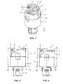
- the in Fig. 1 shown boring head has a tool body 2, which has a fastening pin 8 on an underside, with which the boring head 1 can be fastened in a manner known per se to a drive.
- a transversely through the mounting pin 8 running bolt 9 serves to prevent rotation.
- two blade carriers 3 and 4 are mounted radially displaceable.
- a cutting plate 5 is fixed in each case with a fastening screw 6, which projects beyond an end face 17 in each case axially.
- the cutting plates 5 may be formed as inserts.
- the two blade carriers 3 and 4 are each secured with a clamping screw 7 on the tool body 2.
- the clamping screws 7 each pass through a slot 18 and 25 and are each inserted into a threaded hole, not shown here, of the tool carrier 2. If the clamping screws 7 are released, the two blade carriers 3 and 4 can each be displaced radially independently of one another, as far as this is permitted by the oblong holes 18.
- the intended positions are each defined by a stop, according to Fig. 4 each formed by an adjusting screw 15. These adjusting screws 15 are each rotated by 180 ° in a carrier 16. At the undersides of the blade carriers 3 and 4 16 corresponding recesses not shown here are provided for these adjusting screws 15 and carrier.
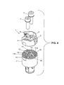
- the two blade carriers 3 and 4 are connected to the tool body 2 via a toothing 10 with each other.
- This toothing comprises a toothing 12 of a clamping surface 11 of the tool body 2 and toothings 13 of the two blade carriers 3 and 4.
- the toothings 12 and 13 are formed corresponding to one another, so that they engage correspondingly.
- the teeth 12 of the clamping surface 11 has two partial clamping surfaces 11 a and 11 b, which are formed semicircular and offset from each other in the axial direction.
- This axial offset is drawn for illustrative reasons excessive. The measure of this displacement is actually much smaller, for example 0.2 mm Fig. 8
- two heights h1 and h2 are provided, each of which means the distance of the part clamping surfaces 11a and 11b with respect to a clamping surface 19 of the tool body.
- the height h1 is 28.1 mm and the height h2 is 28.3 mm.
- the two blade carriers 3 and 4 are according to Fig. 6 in the axial direction of different heights.
- the difference between the heights h3 and h4 is also drawn here too high and is, for example, 0.2 mm.
- the height h3 is here 20.4 mm and the height h4 20.2 mm.
- the difference between h1 and h2 is thus equal to the difference between h3 and h4.
- the heights h3 and h4 each relate to the distance between the toothing 13 and the cutting edge of the cutting plate 5.
- the teeth on the tool carrier 2 'provided 12' is as shown in cross section rectangular and corresponding to the toothing 13 'is formed. The said axial height differences are also provided in this boring head 1 '. The teeth can thus be designed differently.
- the blade carriers 3 and 4 or 3 'and 4' are identical with the exception of the mentioned height differences. They can thus be exchanged for each other. Due to the differences in height mentioned the cutting plates 5 are according FIG. 2 rotationally symmetric or according to Fig. 3 arranged offset at least axially. In the arrangement according to Fig. 3 the cutting edge 5 of the cutter carrier 3 is arranged at a height H1 and the cutting plate 5 of the cutter carrier 4 at a height H2.
- the height difference here is the sum of the height difference between the part clamping surfaces 11a and 11b and the height difference of the two blade carriers 3 and 4. This difference is thus 0.4 mm in the example shown.
- the cutting edge arrangement according to Fig. 3 is an offset and especially double-offset roughing possible.
- the cutting plates 5 are offset both in diameter and in height or axially. This allows in particular the cutting of the double material addition at half the feed values and excellent tension control.
- the material addition is here, for example, 20% of the final diameter.
- the gearing 10 is advantageous in terms of stability, but not mandatory.
- the toothing 10 can thus also be replaced by flat surfaces.
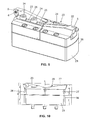
- the in Fig. 9 shown boring head 20 is suitable for larger diameters of, for example, 200 to 600 mm. It is also suitable for the above-mentioned Schrupparten.
- the boring head 1 has an elongated bridge sole 21, on which two intermediate parts 27 and 28 are attached. The two intermediate parts 27 and 28 are clamped with fastening screws 33 against a top 37 of the brine 21. For this purpose, fastening screws 33 and in the brine 21 threaded holes 36 are provided. To the Subpages of the intermediate parts 27 and 28 are also arranged pins not shown here, which engage in holes 35 of the brine 21.
- the threaded bores 36 and the bores 35 are arranged so that they form a grid for different diameter positions.
- the two intermediate parts 27 and 28 can according to Fig. 9 be arranged substantially without space or at a distance to each other, so that a larger diameter can be edited.
- the said pins allow a sufficient stability even with the size diameter.
- the brine 21 and the two intermediate parts 27 and 28 form a tool body.
- the two intermediate parts 27 and 28 each have on top a groove 29 and 30, which are aligned with each other and which are provided for supporting a cutter support 22 and 23, respectively.
- adjusting screws 32 are arranged as radial stops for blade carrier 22 and 23.
- These blade carriers 22 and 23 each have two elongated holes 25 in which clamping screws 24 can be inserted, which are screwed into threaded bores 31 to set the blade carrier 22 and 23 in the intermediate part 27 and 28 respectively. If the clamping screws 24 are released, then the two cutter carriers 22 and 23 can each be adjusted radially independently of one another corresponding to the oblong holes 25.
- the intended positions are defined by the adjusting screws 32.
- a partial clamping surface 26a and 26b against which the blade carrier 22 and 23 is tensioned.
- These partial clamping surfaces 26a and 26b are according to Fig. 12 with respect to the top 37 of the brine 21 differently high.
- the partial clamping surface 26a has the height h1
- the partial clamping surface 26b has the height h2.
- the height difference is also in this case 0.2 mm. In the drawing 12, this height difference is exaggerated for reasons of drawing.
- the height h1 is in the illustrated embodiment 15, 6 mm and the height h2 16 mm.
- the two blade carriers 22 and 23 are also different heights. So is the in Fig. 12 height h3 34 mm and height h4 34.4 mm. At the in Fig. 12 shown arrangement, which according to those Fig. 10 corresponds, the cutting edge of the cutter carrier 23 is thus with respect to the cutting edge 5 of the cutter carrier 22 by 0.8 mm added. If the two blade carriers 22 and 23 are replaced with respect to each other, then the said axial offset is 0. With this blade arrangement, rotationally symmetrical roughing or solid profile roughing is thus possible. In the cutting arrangement according to the Figures 10 and 12 on the other hand, staggered roughing is possible. The cutting edges can also be radially offset. The boring head 1 thus also allows the above-mentioned Schrupparten.
- a change of the blade assembly is also very easy here. Even with comparatively large diameters, a high stability is ensured.
- the boring head 1 can be fixed in a conventional manner to a drive. For this purpose, three fastening screws 34 are provided, which pass through the brine 21.
Applications Claiming Priority (1)
| Application Number | Priority Date | Filing Date | Title |
|---|---|---|---|
| CH00357/10A CH702834A1 (de) | 2010-03-15 | 2010-03-15 | Ausdrehkopf. |
Publications (2)
| Publication Number | Publication Date |
|---|---|
| EP2366477A1 true EP2366477A1 (fr) | 2011-09-21 |
| EP2366477B1 EP2366477B1 (fr) | 2012-08-22 |
Family
ID=42735450
Family Applications (1)
| Application Number | Title | Priority Date | Filing Date |
|---|---|---|---|
| EP11405211A Active EP2366477B1 (fr) | 2010-03-15 | 2011-02-16 | Tête à aléser |
Country Status (8)
| Country | Link |
|---|---|
| US (1) | US8747034B2 (fr) |
| EP (1) | EP2366477B1 (fr) |
| JP (2) | JP5455953B2 (fr) |
| KR (1) | KR101707017B1 (fr) |
| CN (1) | CN102189280B (fr) |
| CH (1) | CH702834A1 (fr) |
| EA (1) | EA020495B1 (fr) |
| TW (1) | TWI554346B (fr) |
Families Citing this family (11)
| Publication number | Priority date | Publication date | Assignee | Title |
|---|---|---|---|---|
| US9004827B2 (en) * | 2007-06-07 | 2015-04-14 | Allied Machine & Engineering Corp. | Adjustable indexable drill and modular system and holder |
| MX2009013301A (es) * | 2007-06-07 | 2010-02-15 | Vmaxx Inc | Perforador indexable ajustable. |
| CH702834A1 (de) * | 2010-03-15 | 2011-09-15 | Kaiser Heinz Ag | Ausdrehkopf. |
| WO2013133118A1 (fr) | 2012-03-06 | 2013-09-12 | 日産自動車株式会社 | Procédé de finition d'une surface revêtue par pulvérisation et outil de travail |
| CN104646699B (zh) * | 2015-02-03 | 2017-01-18 | 成都成林数控刀具有限公司 | 一种带有齿纹偏心啮合结构的可调式双刃大直径镗刀 |
| DE102015207108A1 (de) * | 2015-04-20 | 2016-10-20 | Schaeffler Technologies AG & Co. KG | Messeinrichtung für eine Werkzeugmaschine und entsprechende Werkzeugmaschine |
| EP3456442A1 (fr) * | 2017-09-15 | 2019-03-20 | Sandvik Intellectual Property AB | Outil tournant et procédé pour le coupage de métaux |
| CN108274023A (zh) * | 2018-02-24 | 2018-07-13 | 中信戴卡股份有限公司 | 一种车轮机加刀具 |
| CN110496976A (zh) * | 2018-05-17 | 2019-11-26 | 昆山科森科技股份有限公司 | 用于电子笔杆加工的刀柄和刀粒机构 |
| TWI704020B (zh) * | 2019-03-13 | 2020-09-11 | 鑫峰精機股份有限公司 | 可調式精搪刀 |
| US11618091B2 (en) * | 2019-10-03 | 2023-04-04 | Iscar, Ltd. | Tool holder having simultaneous radially adjustable insert cartridges and rotary cutting tool |
Citations (7)
| Publication number | Priority date | Publication date | Assignee | Title |
|---|---|---|---|---|
| CH262307A (fr) | 1944-02-10 | 1949-06-30 | Energa | Projectile explosif perforant. |
| DE2611146A1 (de) * | 1975-04-24 | 1976-11-11 | Schmalkalden Werkzeug | Zweischneidiges ausbohrwerkzeug |
| CH611190A5 (fr) | 1975-07-26 | 1979-05-31 | Komet Stahlhalter Werkzeug | |
| CH627676A5 (de) | 1978-05-11 | 1982-01-29 | Kaiser Heinz Ag | Zweischneider-ausdrehkopf. |
| EP0564425A1 (fr) * | 1992-02-24 | 1993-10-06 | Sandvik Aktiebolag | Outil d'alésage |
| EP0835709A1 (fr) * | 1996-10-08 | 1998-04-15 | Kaiser Precision Tooling, Inc. | Dispositif d'ajustement pour outils de machine-outil |
| EP0990477A2 (fr) * | 1998-10-02 | 2000-04-05 | Heinz Kaiser AG | Boring head |
Family Cites Families (19)
| Publication number | Priority date | Publication date | Assignee | Title |
|---|---|---|---|---|
| US2402650A (en) * | 1945-03-23 | 1946-06-25 | Anthony J Maffia | Adjustable cutter head |
| US3625624A (en) * | 1970-01-13 | 1971-12-07 | Galaxy Wedgebore Corp | Cutting assembly |
| SU596382A1 (ru) * | 1976-07-19 | 1978-03-05 | Всесоюзный Научно-Исследовательский Инструментальный Институт | Расточна головка |
| US4101239A (en) * | 1977-06-06 | 1978-07-18 | Emil Wohlhaupter U. Co. | Boring tool provided with a pair of separately adjustable cutters |
| DE3204923A1 (de) * | 1982-02-12 | 1983-08-25 | Stellram GmbH, 6056 Heusenstamm | Werkzeug zum aufbohren von bohrungen |
| SU1046031A1 (ru) * | 1982-03-09 | 1983-10-07 | Одесский Проектно-Конструкторский Технологический Институт Научно-Производственного Объединения "Спецтехоснастка" | Расточной инструмент |
| DE3333495A1 (de) * | 1983-09-16 | 1985-03-28 | J. Kühn GmbH & Co Präzisionswerkzeug KG, 4270 Dorsten | Drehbares zerspanungswerkzeug, insbesondere ausbohrkopf od. dgl. |
| SU1328077A1 (ru) * | 1985-07-30 | 1987-08-07 | Донецкий политехнический институт | Расточна головка |
| DE3916564A1 (de) * | 1989-05-20 | 1990-11-22 | Komet Stahlhalter Werkzeug | Werkzeug mit verstellbarer wechselkassette |
| JPH03130302U (fr) * | 1990-04-16 | 1991-12-27 | ||
| CN1066084C (zh) * | 1998-09-14 | 2001-05-23 | 谢和顺 | 具有显示微调搪孔径切削量的粗搪孔刀具 |
| CN2573122Y (zh) * | 2002-09-20 | 2003-09-17 | 昆山力捷塑胶五金有限公司 | 搪孔刀座调整结构 |
| DE10315394A1 (de) * | 2003-04-04 | 2004-11-04 | Sandvik Ab | Ausbohrwerkzeug |
| IL157032A (en) * | 2003-07-21 | 2007-10-31 | Moshe Elbaz | Cutting head for rotary cutting tool |
| CN2748210Y (zh) * | 2004-11-12 | 2005-12-28 | 哈尔滨量具刃具集团有限责任公司 | 错齿可转位面铣刀 |
| ITMI20061909A1 (it) * | 2006-10-04 | 2008-04-05 | D Andrea Spa | Utensile per forare e alesare munito di taglienti registrabili |
| JP2009262307A (ja) * | 2008-04-28 | 2009-11-12 | Daishowa Seiki Co Ltd | ボーリング工具 |
| CN201376098Y (zh) * | 2009-03-21 | 2010-01-06 | 山东普利森集团有限公司 | 大型机夹镗头 |
| CH702834A1 (de) * | 2010-03-15 | 2011-09-15 | Kaiser Heinz Ag | Ausdrehkopf. |
-
2010
- 2010-03-15 CH CH00357/10A patent/CH702834A1/de not_active Application Discontinuation
-
2011
- 2011-02-16 EP EP11405211A patent/EP2366477B1/fr active Active
- 2011-02-25 TW TW100106423A patent/TWI554346B/zh active
- 2011-03-07 CN CN201110054873.7A patent/CN102189280B/zh active Active
- 2011-03-14 JP JP2011055046A patent/JP5455953B2/ja not_active Expired - Fee Related
- 2011-03-15 US US13/048,152 patent/US8747034B2/en active Active
- 2011-03-15 EA EA201170341A patent/EA020495B1/ru unknown
- 2011-03-15 KR KR1020110022964A patent/KR101707017B1/ko active IP Right Grant
-
2013
- 2013-10-25 JP JP2013221854A patent/JP5711804B2/ja active Active
Patent Citations (8)
| Publication number | Priority date | Publication date | Assignee | Title |
|---|---|---|---|---|
| CH262307A (fr) | 1944-02-10 | 1949-06-30 | Energa | Projectile explosif perforant. |
| DE2611146A1 (de) * | 1975-04-24 | 1976-11-11 | Schmalkalden Werkzeug | Zweischneidiges ausbohrwerkzeug |
| CH611190A5 (fr) | 1975-07-26 | 1979-05-31 | Komet Stahlhalter Werkzeug | |
| CH627676A5 (de) | 1978-05-11 | 1982-01-29 | Kaiser Heinz Ag | Zweischneider-ausdrehkopf. |
| EP0564425A1 (fr) * | 1992-02-24 | 1993-10-06 | Sandvik Aktiebolag | Outil d'alésage |
| EP0835709A1 (fr) * | 1996-10-08 | 1998-04-15 | Kaiser Precision Tooling, Inc. | Dispositif d'ajustement pour outils de machine-outil |
| EP0990477A2 (fr) * | 1998-10-02 | 2000-04-05 | Heinz Kaiser AG | Boring head |
| EP0990477B1 (fr) | 1998-10-02 | 2005-01-05 | Heinz Kaiser AG | Boring head |
Also Published As
| Publication number | Publication date |
|---|---|
| EP2366477B1 (fr) | 2012-08-22 |
| JP2014012339A (ja) | 2014-01-23 |
| TW201206592A (en) | 2012-02-16 |
| US20110222979A1 (en) | 2011-09-15 |
| JP5711804B2 (ja) | 2015-05-07 |
| CH702834A1 (de) | 2011-09-15 |
| KR20110103892A (ko) | 2011-09-21 |
| US8747034B2 (en) | 2014-06-10 |
| TWI554346B (zh) | 2016-10-21 |
| JP2011189504A (ja) | 2011-09-29 |
| CN102189280B (zh) | 2014-12-24 |
| EA201170341A1 (ru) | 2011-10-31 |
| CN102189280A (zh) | 2011-09-21 |
| JP5455953B2 (ja) | 2014-03-26 |
| KR101707017B1 (ko) | 2017-02-15 |
| EA020495B1 (ru) | 2014-11-28 |
Similar Documents
| Publication | Publication Date | Title |
|---|---|---|
| EP2366477B1 (fr) | Tête à aléser | |
| EP1531023B1 (fr) | Plaquette de forage qui est tenu serré dans un corps de base | |
| EP0674560B1 (fr) | Outil de forage a piece de coupe rapportee interchangeable | |
| EP2560778B1 (fr) | Tête de forage pour un outil de forage profond destiné au forage profond bta et outil de forage profond | |
| EP1885517B1 (fr) | Porte-outil a reglage precis | |
| EP2846049B1 (fr) | Système de fixation avec système excentrique | |
| EP0674561A1 (fr) | Foret plein | |
| EP2208566B1 (fr) | Outil de coupe avec couteau de coupe par enlèvement et méthode pour attacher le couteau de coupe à l'outil de coupe | |
| EP2401105B1 (fr) | Outil d'usinage avec plaquette réglable ainsi que son utilisation et procédé d'ajuster le même | |
| EP3233339B1 (fr) | Outil d'usinage par enlèvement de copeaux | |
| EP2895289B1 (fr) | Outil d'usinage de pièces par enlèvement de matière | |
| DE102011012663B4 (de) | Messerhalterung zur Befestigung eines Hackmessers | |
| DE102005032761A1 (de) | Messerkopf | |
| DE2533495C3 (de) | Bohrstange | |
| DE102009024061B4 (de) | Maschinenreibahle | |
| EP0175011A1 (fr) | Outil de coupe rotatif en particulier tête de foreuse | |
| EP0113097A2 (fr) | Alésoir réglable pour machines | |
| DE19514979B4 (de) | Schrägbohrvorrichtung | |
| EP3292931B1 (fr) | Outil, notamment pour l'usinage de pièces à enlèvement de copeaux | |
| DE202009010943U1 (de) | Werkzeug zur spanabhebenden Bearbeitung von Werkstücken | |
| DE10238451A1 (de) | Scheibenförmiges oder leistenförmiges Werkzeug | |
| WO2020152040A1 (fr) | Outil de machine | |
| DE202015101365U1 (de) | Spannfutter | |
| DE10129399B4 (de) | Maschinenreibahle und zugehörige Schneidplatte | |
| EP0012211A1 (fr) | Alésoir pour machines |
Legal Events
| Date | Code | Title | Description |
|---|---|---|---|
| PUAI | Public reference made under article 153(3) epc to a published international application that has entered the european phase |
Free format text: ORIGINAL CODE: 0009012 |
|
| AK | Designated contracting states |
Kind code of ref document: A1 Designated state(s): AL AT BE BG CH CY CZ DE DK EE ES FI FR GB GR HR HU IE IS IT LI LT LU LV MC MK MT NL NO PL PT RO RS SE SI SK SM TR |
|
| AX | Request for extension of the european patent |
Extension state: BA ME |
|
| 17P | Request for examination filed |
Effective date: 20111215 |
|
| GRAP | Despatch of communication of intention to grant a patent |
Free format text: ORIGINAL CODE: EPIDOSNIGR1 |
|
| GRAS | Grant fee paid |
Free format text: ORIGINAL CODE: EPIDOSNIGR3 |
|
| GRAA | (expected) grant |
Free format text: ORIGINAL CODE: 0009210 |
|
| AK | Designated contracting states |
Kind code of ref document: B1 Designated state(s): AL AT BE BG CH CY CZ DE DK EE ES FI FR GB GR HR HU IE IS IT LI LT LU LV MC MK MT NL NO PL PT RO RS SE SI SK SM TR |
|
| REG | Reference to a national code |
Ref country code: GB Ref legal event code: FG4D Free format text: NOT ENGLISH |
|
| REG | Reference to a national code |
Ref country code: CH Ref legal event code: EP |
|
| REG | Reference to a national code |
Ref country code: IE Ref legal event code: FG4D Free format text: LANGUAGE OF EP DOCUMENT: GERMAN |
|
| REG | Reference to a national code |
Ref country code: AT Ref legal event code: REF Ref document number: 571672 Country of ref document: AT Kind code of ref document: T Effective date: 20120915 |
|
| REG | Reference to a national code |
Ref country code: CH Ref legal event code: NV Representative=s name: ISLER & PEDRAZZINI AG |
|
| REG | Reference to a national code |
Ref country code: DE Ref legal event code: R096 Ref document number: 502011000076 Country of ref document: DE Effective date: 20121018 |
|
| REG | Reference to a national code |
Ref country code: SE Ref legal event code: TRGR |
|
| REG | Reference to a national code |
Ref country code: NL Ref legal event code: VDEP Effective date: 20120822 |
|
| REG | Reference to a national code |
Ref country code: LT Ref legal event code: MG4D Effective date: 20120822 |
|
| PG25 | Lapsed in a contracting state [announced via postgrant information from national office to epo] |
Ref country code: IS Free format text: LAPSE BECAUSE OF FAILURE TO SUBMIT A TRANSLATION OF THE DESCRIPTION OR TO PAY THE FEE WITHIN THE PRESCRIBED TIME-LIMIT Effective date: 20121222 Ref country code: LT Free format text: LAPSE BECAUSE OF FAILURE TO SUBMIT A TRANSLATION OF THE DESCRIPTION OR TO PAY THE FEE WITHIN THE PRESCRIBED TIME-LIMIT Effective date: 20120822 Ref country code: HR Free format text: LAPSE BECAUSE OF FAILURE TO SUBMIT A TRANSLATION OF THE DESCRIPTION OR TO PAY THE FEE WITHIN THE PRESCRIBED TIME-LIMIT Effective date: 20120822 Ref country code: NO Free format text: LAPSE BECAUSE OF FAILURE TO SUBMIT A TRANSLATION OF THE DESCRIPTION OR TO PAY THE FEE WITHIN THE PRESCRIBED TIME-LIMIT Effective date: 20121122 Ref country code: FI Free format text: LAPSE BECAUSE OF FAILURE TO SUBMIT A TRANSLATION OF THE DESCRIPTION OR TO PAY THE FEE WITHIN THE PRESCRIBED TIME-LIMIT Effective date: 20120822 |
|
| PG25 | Lapsed in a contracting state [announced via postgrant information from national office to epo] |
Ref country code: LV Free format text: LAPSE BECAUSE OF FAILURE TO SUBMIT A TRANSLATION OF THE DESCRIPTION OR TO PAY THE FEE WITHIN THE PRESCRIBED TIME-LIMIT Effective date: 20120822 Ref country code: GR Free format text: LAPSE BECAUSE OF FAILURE TO SUBMIT A TRANSLATION OF THE DESCRIPTION OR TO PAY THE FEE WITHIN THE PRESCRIBED TIME-LIMIT Effective date: 20121123 Ref country code: SI Free format text: LAPSE BECAUSE OF FAILURE TO SUBMIT A TRANSLATION OF THE DESCRIPTION OR TO PAY THE FEE WITHIN THE PRESCRIBED TIME-LIMIT Effective date: 20120822 Ref country code: PT Free format text: LAPSE BECAUSE OF FAILURE TO SUBMIT A TRANSLATION OF THE DESCRIPTION OR TO PAY THE FEE WITHIN THE PRESCRIBED TIME-LIMIT Effective date: 20121224 |
|
| PG25 | Lapsed in a contracting state [announced via postgrant information from national office to epo] |
Ref country code: NL Free format text: LAPSE BECAUSE OF FAILURE TO SUBMIT A TRANSLATION OF THE DESCRIPTION OR TO PAY THE FEE WITHIN THE PRESCRIBED TIME-LIMIT Effective date: 20120822 |
|
| PG25 | Lapsed in a contracting state [announced via postgrant information from national office to epo] |
Ref country code: RO Free format text: LAPSE BECAUSE OF FAILURE TO SUBMIT A TRANSLATION OF THE DESCRIPTION OR TO PAY THE FEE WITHIN THE PRESCRIBED TIME-LIMIT Effective date: 20120822 Ref country code: EE Free format text: LAPSE BECAUSE OF FAILURE TO SUBMIT A TRANSLATION OF THE DESCRIPTION OR TO PAY THE FEE WITHIN THE PRESCRIBED TIME-LIMIT Effective date: 20120822 Ref country code: DK Free format text: LAPSE BECAUSE OF FAILURE TO SUBMIT A TRANSLATION OF THE DESCRIPTION OR TO PAY THE FEE WITHIN THE PRESCRIBED TIME-LIMIT Effective date: 20120822 Ref country code: CZ Free format text: LAPSE BECAUSE OF FAILURE TO SUBMIT A TRANSLATION OF THE DESCRIPTION OR TO PAY THE FEE WITHIN THE PRESCRIBED TIME-LIMIT Effective date: 20120822 |
|
| PG25 | Lapsed in a contracting state [announced via postgrant information from national office to epo] |
Ref country code: PL Free format text: LAPSE BECAUSE OF FAILURE TO SUBMIT A TRANSLATION OF THE DESCRIPTION OR TO PAY THE FEE WITHIN THE PRESCRIBED TIME-LIMIT Effective date: 20120822 Ref country code: SK Free format text: LAPSE BECAUSE OF FAILURE TO SUBMIT A TRANSLATION OF THE DESCRIPTION OR TO PAY THE FEE WITHIN THE PRESCRIBED TIME-LIMIT Effective date: 20120822 |
|
| PLBE | No opposition filed within time limit |
Free format text: ORIGINAL CODE: 0009261 |
|
| STAA | Information on the status of an ep patent application or granted ep patent |
Free format text: STATUS: NO OPPOSITION FILED WITHIN TIME LIMIT |
|
| 26N | No opposition filed |
Effective date: 20130523 |
|
| PG25 | Lapsed in a contracting state [announced via postgrant information from national office to epo] |
Ref country code: RS Free format text: LAPSE BECAUSE OF FAILURE TO SUBMIT A TRANSLATION OF THE DESCRIPTION OR TO PAY THE FEE WITHIN THE PRESCRIBED TIME-LIMIT Effective date: 20120822 Ref country code: BG Free format text: LAPSE BECAUSE OF FAILURE TO SUBMIT A TRANSLATION OF THE DESCRIPTION OR TO PAY THE FEE WITHIN THE PRESCRIBED TIME-LIMIT Effective date: 20121122 |
|
| BERE | Be: lapsed |
Owner name: HEINZ KAISER A.G. Effective date: 20130228 |
|
| REG | Reference to a national code |
Ref country code: DE Ref legal event code: R097 Ref document number: 502011000076 Country of ref document: DE Effective date: 20130523 |
|
| PG25 | Lapsed in a contracting state [announced via postgrant information from national office to epo] |
Ref country code: MC Free format text: LAPSE BECAUSE OF NON-PAYMENT OF DUE FEES Effective date: 20130228 |
|
| PG25 | Lapsed in a contracting state [announced via postgrant information from national office to epo] |
Ref country code: ES Free format text: LAPSE BECAUSE OF FAILURE TO SUBMIT A TRANSLATION OF THE DESCRIPTION OR TO PAY THE FEE WITHIN THE PRESCRIBED TIME-LIMIT Effective date: 20121203 |
|
| PG25 | Lapsed in a contracting state [announced via postgrant information from national office to epo] |
Ref country code: CY Free format text: LAPSE BECAUSE OF FAILURE TO SUBMIT A TRANSLATION OF THE DESCRIPTION OR TO PAY THE FEE WITHIN THE PRESCRIBED TIME-LIMIT Effective date: 20120822 |
|
| REG | Reference to a national code |
Ref country code: IE Ref legal event code: MM4A |
|
| PG25 | Lapsed in a contracting state [announced via postgrant information from national office to epo] |
Ref country code: BE Free format text: LAPSE BECAUSE OF NON-PAYMENT OF DUE FEES Effective date: 20130228 Ref country code: AL Free format text: LAPSE BECAUSE OF FAILURE TO SUBMIT A TRANSLATION OF THE DESCRIPTION OR TO PAY THE FEE WITHIN THE PRESCRIBED TIME-LIMIT Effective date: 20120822 Ref country code: IE Free format text: LAPSE BECAUSE OF NON-PAYMENT OF DUE FEES Effective date: 20130216 |
|
| PG25 | Lapsed in a contracting state [announced via postgrant information from national office to epo] |
Ref country code: MT Free format text: LAPSE BECAUSE OF FAILURE TO SUBMIT A TRANSLATION OF THE DESCRIPTION OR TO PAY THE FEE WITHIN THE PRESCRIBED TIME-LIMIT Effective date: 20120822 |
|
| REG | Reference to a national code |
Ref country code: FR Ref legal event code: PLFP Year of fee payment: 5 |
|
| REG | Reference to a national code |
Ref country code: DE Ref legal event code: R082 Ref document number: 502011000076 Country of ref document: DE Representative=s name: PATENTANWAELTE WEICKMANN & WEICKMANN, DE Ref country code: DE Ref legal event code: R082 Ref document number: 502011000076 Country of ref document: DE Representative=s name: WEICKMANN & WEICKMANN PATENTANWAELTE - RECHTSA, DE Ref country code: DE Ref legal event code: R082 Ref document number: 502011000076 Country of ref document: DE Representative=s name: WEICKMANN & WEICKMANN PATENT- UND RECHTSANWAEL, DE |
|
| PG25 | Lapsed in a contracting state [announced via postgrant information from national office to epo] |
Ref country code: SM Free format text: LAPSE BECAUSE OF FAILURE TO SUBMIT A TRANSLATION OF THE DESCRIPTION OR TO PAY THE FEE WITHIN THE PRESCRIBED TIME-LIMIT Effective date: 20120822 |
|
| PG25 | Lapsed in a contracting state [announced via postgrant information from national office to epo] |
Ref country code: TR Free format text: LAPSE BECAUSE OF FAILURE TO SUBMIT A TRANSLATION OF THE DESCRIPTION OR TO PAY THE FEE WITHIN THE PRESCRIBED TIME-LIMIT Effective date: 20120822 |
|
| PG25 | Lapsed in a contracting state [announced via postgrant information from national office to epo] |
Ref country code: LU Free format text: LAPSE BECAUSE OF NON-PAYMENT OF DUE FEES Effective date: 20130216 Ref country code: HU Free format text: LAPSE BECAUSE OF FAILURE TO SUBMIT A TRANSLATION OF THE DESCRIPTION OR TO PAY THE FEE WITHIN THE PRESCRIBED TIME-LIMIT; INVALID AB INITIO Effective date: 20110216 Ref country code: MK Free format text: LAPSE BECAUSE OF FAILURE TO SUBMIT A TRANSLATION OF THE DESCRIPTION OR TO PAY THE FEE WITHIN THE PRESCRIBED TIME-LIMIT Effective date: 20120822 |
|
| GBPC | Gb: european patent ceased through non-payment of renewal fee |
Effective date: 20150216 |
|
| PG25 | Lapsed in a contracting state [announced via postgrant information from national office to epo] |
Ref country code: GB Free format text: LAPSE BECAUSE OF NON-PAYMENT OF DUE FEES Effective date: 20150216 |
|
| REG | Reference to a national code |
Ref country code: FR Ref legal event code: PLFP Year of fee payment: 6 |
|
| REG | Reference to a national code |
Ref country code: FR Ref legal event code: PLFP Year of fee payment: 7 |
|
| REG | Reference to a national code |
Ref country code: AT Ref legal event code: MM01 Ref document number: 571672 Country of ref document: AT Kind code of ref document: T Effective date: 20160216 |
|
| PG25 | Lapsed in a contracting state [announced via postgrant information from national office to epo] |
Ref country code: AT Free format text: LAPSE BECAUSE OF NON-PAYMENT OF DUE FEES Effective date: 20160216 |
|
| REG | Reference to a national code |
Ref country code: FR Ref legal event code: PLFP Year of fee payment: 8 |
|
| PGFP | Annual fee paid to national office [announced via postgrant information from national office to epo] |
Ref country code: FR Payment date: 20230221 Year of fee payment: 13 Ref country code: CH Payment date: 20230307 Year of fee payment: 13 |
|
| PGFP | Annual fee paid to national office [announced via postgrant information from national office to epo] |
Ref country code: SE Payment date: 20230216 Year of fee payment: 13 Ref country code: IT Payment date: 20230217 Year of fee payment: 13 |
|
| PGFP | Annual fee paid to national office [announced via postgrant information from national office to epo] |
Ref country code: DE Payment date: 20240219 Year of fee payment: 14 Ref country code: CH Payment date: 20240301 Year of fee payment: 14 |