US11618091B2 - Tool holder having simultaneous radially adjustable insert cartridges and rotary cutting tool - Google Patents
Tool holder having simultaneous radially adjustable insert cartridges and rotary cutting tool Download PDFInfo
- Publication number
- US11618091B2 US11618091B2 US16/591,765 US201916591765A US11618091B2 US 11618091 B2 US11618091 B2 US 11618091B2 US 201916591765 A US201916591765 A US 201916591765A US 11618091 B2 US11618091 B2 US 11618091B2
- Authority
- US
- United States
- Prior art keywords
- sleeve
- cartridge
- engagement
- insert
- holder
- Prior art date
- Legal status (The legal status is an assumption and is not a legal conclusion. Google has not performed a legal analysis and makes no representation as to the accuracy of the status listed.)
- Active, expires
Links
Images


Classifications
-
- B—PERFORMING OPERATIONS; TRANSPORTING
- B23—MACHINE TOOLS; METAL-WORKING NOT OTHERWISE PROVIDED FOR
- B23B—TURNING; BORING
- B23B27/00—Tools for turning or boring machines; Tools of a similar kind in general; Accessories therefor
- B23B27/14—Cutting tools of which the bits or tips or cutting inserts are of special material
- B23B27/16—Cutting tools of which the bits or tips or cutting inserts are of special material with exchangeable cutting bits or cutting inserts, e.g. able to be clamped
- B23B27/1603—Cutting tools of which the bits or tips or cutting inserts are of special material with exchangeable cutting bits or cutting inserts, e.g. able to be clamped with specially shaped plate-like exchangeable cutting inserts, e.g. chip-breaking groove
- B23B27/1611—Cutting tools of which the bits or tips or cutting inserts are of special material with exchangeable cutting bits or cutting inserts, e.g. able to be clamped with specially shaped plate-like exchangeable cutting inserts, e.g. chip-breaking groove characterised by having a special shape
-
- B—PERFORMING OPERATIONS; TRANSPORTING
- B23—MACHINE TOOLS; METAL-WORKING NOT OTHERWISE PROVIDED FOR
- B23B—TURNING; BORING
- B23B29/00—Holders for non-rotary cutting tools; Boring bars or boring heads; Accessories for tool holders
- B23B29/03—Boring heads
- B23B29/034—Boring heads with tools moving radially, e.g. for making chamfers or undercuttings
- B23B29/03403—Boring heads with tools moving radially, e.g. for making chamfers or undercuttings radially adjustable before starting manufacturing
-
- B—PERFORMING OPERATIONS; TRANSPORTING
- B23—MACHINE TOOLS; METAL-WORKING NOT OTHERWISE PROVIDED FOR
- B23B—TURNING; BORING
- B23B29/00—Holders for non-rotary cutting tools; Boring bars or boring heads; Accessories for tool holders
- B23B29/03—Boring heads
- B23B29/034—Boring heads with tools moving radially, e.g. for making chamfers or undercuttings
-
- B—PERFORMING OPERATIONS; TRANSPORTING
- B23—MACHINE TOOLS; METAL-WORKING NOT OTHERWISE PROVIDED FOR
- B23B—TURNING; BORING
- B23B2200/00—Details of cutting inserts
- B23B2200/04—Overall shape
- B23B2200/0471—Square
-
- B—PERFORMING OPERATIONS; TRANSPORTING
- B23—MACHINE TOOLS; METAL-WORKING NOT OTHERWISE PROVIDED FOR
- B23B—TURNING; BORING
- B23B2260/00—Details of constructional elements
- B23B2260/02—Cams
-
- B—PERFORMING OPERATIONS; TRANSPORTING
- B23—MACHINE TOOLS; METAL-WORKING NOT OTHERWISE PROVIDED FOR
- B23B—TURNING; BORING
- B23B2260/00—Details of constructional elements
- B23B2260/03—Clamps
-
- B—PERFORMING OPERATIONS; TRANSPORTING
- B23—MACHINE TOOLS; METAL-WORKING NOT OTHERWISE PROVIDED FOR
- B23B—TURNING; BORING
- B23B2260/00—Details of constructional elements
- B23B2260/072—Grooves
- B23B2260/0725—Spiral
-
- B—PERFORMING OPERATIONS; TRANSPORTING
- B23—MACHINE TOOLS; METAL-WORKING NOT OTHERWISE PROVIDED FOR
- B23B—TURNING; BORING
- B23B2260/00—Details of constructional elements
- B23B2260/088—Indication scales
Definitions
- the subject matter of the present application relates to rotary cutting tools having a tool holder having a plurality of insert cartridges retained thereon, in general, and to such cutting tools with an arrangement for simultaneously adjusting the radial position of the insert cartridges, in particular.
- Rotary cutting tools having a plurality of peripheral insert cartridges with a cutting insert retained in a circumferentially disposed insert pocket formed on the insert cartridge, can be provided with an adjustment mechanism for adjusting the radial position of any of said insert cartridges and thereby the respective cutting insert seated thereon.
- Examples of such rotary cutting tools are disclosed in, for example, GB 2466660B2, GB 328803A and WO 2012/101319.
- a tool holder configured for rotation about a holder central axis defining opposite axially forward and rearward directions, and opposite rotational preceding and succeeding directions with the preceding direction being the cutting direction, the tool holder comprising:
- a rotary cutting tool comprising:
- each cutting insert releasably retained in a respective insert pocket.
- a tool holder configured for rotation about a holder central axis defining opposite axially forward and rearward directions, and opposite rotational preceding and succeeding directions with the preceding direction being the cutting direction, the tool holder comprising:
- a holder body comprising:
- an adjustment sleeve having a sleeve central axis and comprising:
- a plurality of circumferentially spaced apart insert cartridges each comprising:
- each insert pocket is spaced apart from the holder central axis by a respective second radial pocket distance, the second radial pocket distance being greater than the first radial pocket distance.
- different cartridge pins can define the at least one active cartridge pin, for at least some of the insert cartridges.
- Each sleeve adjustment groove can extend along a spiral.
- Each spiral can be an Archimedean spiral, having a constant separation distance between successive turns.
- the pitch angle of each spiral can be less than 10°.
- the adjustment sleeve can comprise exactly one sleeve adjustment groove, with a spiral center contained at the holder central axis.
- the exactly one sleeve adjustment groove can extend about the sleeve central axis between one and two turns.
- the cartridge pins on the plurality of insert cartridges can project from the cartridge rearward surface of their respective insert cartridges at different locations thereon.
- Each sleeve adjustment groove can intersect at least one of the sleeve through hole wall surface and the sleeve peripheral surface.
- the rotational sleeve direction can be defined by the preceding direction.
- the sleeve peripheral surface can be defined by an imaginary outer sleeve cylinder having an outer sleeve diameter.
- the sleeve through hole wall surface can be defined by an imaginary inner sleeve cylinder having an inner sleeve diameter (D IS ).
- the inner sleeve diameter can be greater than 70% of the outer sleeve diameter.
- two cartridge pins can be located in a respective one of the sleeve adjustment grooves defining two active cartridge pins.
- Each insert cartridge can comprise a plurality of cartridge pins.
- at least one of the cartridge pins may not be located in any of the sleeve adjustment groove ( 62 ), thereby defining an at least one non-active cartridge pin.
- the forward body portion can comprise a plurality of cartridge pin storage channels recessed in the body forward surface, each associated with one of the body engagement surfaces. In the inner adjusted position, for at least one insert cartridge, any non-active cartridge pins which are located radially inwards from the at least one active cartridge pin can be located in one of the cartridge pin storage channels.
- At least one non-active cartridge pin can be located radially outwards from the at least one active cartridge pin.
- Each body engagement surface can comprise at least one linear engagement recess and/or at least one linear engagement projection.
- Each cartridge engagement surface can comprise at least one linear engagement recess and/or at least one linear engagement projection. The at least one engagement projection can be engaged to the at least one engagement recess.
- Each body engagement surface can comprise a plurality of linear engagement recesses and a plurality of linear engagement projection.
- Each cartridge engagement surface can comprise a plurality of linear engagement recesses and a plurality of linear engagement projections.
- the linear engagement recesses can alternate with the linear engagement projections.
- the plurality of linear engagement recesses and the plurality of linear engagement projections can form a serrated engagement between the cartridge engagement surface and the respective body engagement surface.
- Each insert cartridge can comprise a plurality of cartridge pins.
- the plurality of cartridge pins can be arranged in a linear manner, parallel to the at least one linear engagement recess and/or the at least one linear engagement projection located at the cartridge engagement surface.
- the at least one engagement projection and/or the at least one engagement recess provided at each body engagement surface can extend in the inward and outward adjustment directions.
- the inward and outward adjustment directions can be non-perpendicular to an axial pin half-plane containing the holder central axis and intersecting the at least one active cartridge pin.
- the plurality of insert cartridges can be axially clamped to the holder body by a clamping arrangement.
- the forward body portion can comprise a body threaded hole recessed in the body forward surface.
- the clamping arrangement can comprise a clamping plate comprising a plate through hole and a plurality of plate clamping portions.
- the clamping plate can be releasably attached to the tool holder by a plate retaining screw comprising a screw lower threaded portion, the plate retaining screw located in the plate through hole with the screw lower threaded portion threadingly engaged with the body threaded hole.
- Each plate clamping portion can clampingly engage a respective insert cartridge to the holder body.
- Each insert cartridge can comprise a cartridge forward surface opposite the cartridge rearward surface and an elongated cartridge pin recess recessed in the cartridge forward surface.
- the clamping plate can comprise opposite plate forward and rearward surfaces and a plate peripheral surface extending therebetween and a plurality of plate pins projecting from the rearward plate surface.
- a respective plate pin can be located in the cartridge pin recess.
- the plate through hole can comprise a plate through hole threaded portion.
- the plate retaining screw can comprise a screw upper threaded portion, the screw lower threaded portion being of opposite helical direction to the screw upper threaded portion.
- the screw upper threaded portion can be threadingly engaged with the plate through hole threaded portion.
- the adjustment sleeve can comprise a sleeve threaded through hole opening out to the sleeve through hole wall surface and the sleeve peripheral surface.
- the forward body portion can comprise an annular body securing groove recessed in the body peripheral surface and extending about the holder central axis.
- the adjustment sleeve can be releasably attached to the forward body portion by a securing screw located in the body securing groove and threadingly engaged with the sleeve threaded through hole.
- FIG. 1 is a perspective view of a rotary cutting tool
- FIG. 2 is an exploded perspective view of the rotary cutting tool shown in FIG. 1 ;
- FIG. 3 is a side view of a tool holder shown in FIGS. 1 and 2 ;
- FIG. 4 is a front view of the tool holder shown in FIG. 3 ;
- FIG. 5 is a front view of an adjustment sleeve shown in FIGS. 1 and 2 ;
- FIG. 6 is a perspective view of an insert cartridge shown in FIGS. 1 and 2 ;
- FIG. 7 is a top view of the insert cartridge shown in FIG. 6 ;
- FIG. 8 is a bottom view of the insert cartridge shown in FIG. 6 ;
- FIG. 9 is a top view of a clamping plate shown in FIGS. 1 and 2 ;
- FIG. 10 is a bottom view of the clamping plate shown in FIG. 9 ;
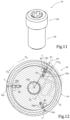
- FIG. 11 is a perspective view of a plate retaining screw shown in FIGS. 1 and 2 ;
- FIG. 12 is a cross sectional view taken in a radial plane when the tool holder is in an inner adjusted position, with the contour of one insert cartridge superimposed thereon;
- FIG. 13 is an analogous view shown in FIG. 12 , when the tool holder is in a first outer adjusted position
- FIG. 14 is an analogous view shown in FIG. 12 , when the tool holder is in a second outer adjusted position, which is further outward than the first outer adjusted position.
- FIGS. 1 and 2 showing a rotary cutting tool 20 , depicting an aspect of the present application.
- the rotary cutting tool 20 is a rotary boring tool, designed to increase the diameter of pre-existing holes.
- the rotary cutting tool 20 includes a tool holder 22 which has a holder body 24 and a plurality of insert cartridges 26 .
- the plurality of insert cartridges 26 are circumferentially spaced apart.
- the tool holder 22 has exactly three insert cartridges 26 .
- the insert cartridges 26 are releasably attached to the holder body 24 .
- the rotary cutting tool 20 further includes a plurality of cutting inserts 28 .
- Each cutting insert 28 has a circumferential cutting edge 29 .
- Each cutting insert 28 is releasably retained in an insert pocket 30 of a respective insert cartridge 26 .
- the rotary cutting tool 20 has a cutting diameter which defines the diameter of the hole in the workpiece after cutting (e.g. boring) has been performed.
- the tool holder 22 is adjustable between an inner adjusted position and an outer adjusted position. The inner adjusted position can correspond to a minimum cutting diameter. The outer adjusted position can correspond to a maximum cutting diameter.
- FIGS. 1 and 2 also showing the tool holder 22 , depicting another aspect of the present application.
- the tool holder 22 is configured to rotate about a holder central axis B.
- the holder central axis B defines opposite axially forward and rearward directions D F , D R .
- the holder central axis B also defines rotational preceding and succeeding directions D P , D S .
- the preceding direction D P is the cutting direction of the rotary cutting tool 20 .
- forward and “rearward” throughout the description and claims refer to a relative position in a direction of the holder central axis B towards the left and right, respectively, in FIG. 3 .
- forward is associated with the cutting end of the rotary cutting tool 20 .
- axial and “radial” throughout the description and claims are with respect to the holder central axis B, unless otherwise stated.
- the tool holder 22 includes a holder body 24 .
- the holder body 24 includes a forwardly disposed forward body portion 32 and a rearwardly disposed spindle portion 34 .
- the spindle portion 34 is designed to receive torque from the CNC machine in order to rotate the tool holder 22 .
- the forward body portion 32 includes a forward facing body forward surface 36 and a body peripheral surface 38 .
- the body forward surface 36 can be oriented perpendicular to the holder central axis B.
- the body peripheral surface 38 extends about the holder central axis B and bounds the body forward surface 36 .
- the body peripheral surface 38 can be defined by an imaginary outer body cylinder C OB which is co-axial with the tool holder 22 and which has an outer body diameter D OB .
- the forward body portion 32 can include a body threaded hole 40 recessed in the body forward surface 36 .
- the body threaded hole 40 is designed to threadingly receive a retaining screw which belongs to a clamping mechanism, and is discussed further on in the description.
- the body threaded hole 40 can extend along the holder central axis B.
- the body forward surface 36 includes a plurality of body engagement surfaces 42 .
- the plurality of body engagement surfaces 42 are circumferentially spaced apart from one another about the holder central axis B and do not overlap one another.
- the plurality of body engagement surfaces 42 are designed to engage corresponding rear cartridge surfaces 66 on the insert cartridges 26 , and are discussed further on in the description.
- the number of body engagement surfaces 42 corresponds to the number of insert cartridges 26 . While in FIG. 4 , the body engagement surfaces 42 are identical to one another, in some embodiments they may differ from one another.
- the tool holder 22 includes an adjustment sleeve 44 .
- the adjustment sleeve 44 has a sleeve central axis A.
- the adjustment sleeve 44 includes opposite forward and rearward sleeve end surfaces 46 , 48 .
- the forward and rearward sleeve end surfaces 46 , 48 can be oriented perpendicular to the sleeve central axis A.
- the adjustment sleeve 44 further includes a sleeve peripheral surface 50 which extends between the forward and rearward sleeve end surfaces 46 , 48 .
- the sleeve peripheral surface 50 extends about the sleeve central axis A.
- the sleeve peripheral surface 50 can be defined by an imaginary outer sleeve cylinder C OS which has the sleeve central axis A as its axis and which has an outer sleeve diameter D OS .
- the adjustment sleeve 44 includes a sleeve through hole 52 .
- the sleeve through hole 52 includes a sleeve through hole wall surface 54 which extends about the sleeve central axis A. Stated differently, the sleeve through hole 52 extends along the sleeve central axis A.
- the sleeve through hole wall surface 54 connects the forward and rearward sleeve end surfaces 46 , 48 . That is to say, the sleeve through hole 52 opens out to the forward and rearward sleeve end surfaces 46 , 48 .
- the adjustment sleeve 44 is circumferentially disposed about the holder body 24 , with the sleeve through hole wall surface 54 facing the body peripheral surface 38 .
- the adjustment sleeve 44 is rotationally displaceable with respect to the forward body portion 32 . That is to say, the adjustment sleeve 44 can be rotated relative to the forward body portion 32 (clearly, the inner sleeve diameter D IS is slightly greater than the outer body diameter D OB so clearance is provided to allow rotation of the adjustment sleeve 44 ).
- the adjustment sleeve 44 and the tool holder 22 are co-axial.
- the forward sleeve surface 46 can be level with the body forward surface 36 in the axial direction when the rotary cutting tool 20 is assembled (see FIG. 1 ).
- the adjustment sleeve 44 can include a sleeve threaded through hole 56 opening out to the sleeve through hole wall surface 54 and the sleeve peripheral surface 50 .
- the sleeve threaded through hole 56 extends in a radial direction relative to the sleeve central axis A.
- the forward body portion 32 can include an annular body securing groove 58 recessed in the body peripheral surface 38 and extending about the holder central axis B. As shown in FIG.
- a securing screw 60 can be threadingly engaged with the sleeve threaded through hole 56 and also located in the body securing groove 58 .
- the securing screw 60 does not firmly abut the body securing groove 58 .
- the adjustment sleeve 44 is releasably attached to the holder body 24 while allowing the adjustment sleeve 44 to be rotated.
- the adjustment sleeve 44 includes at least one sleeve adjustment groove 62 recessed in the forward sleeve end surface 46 .
- the at least one sleeve adjustment groove 62 extends about the sleeve central axis A.
- Each sleeve adjustment groove 62 includes radially inwardly and outwardly facing groove wall surface 63 a , 63 b that oppose each other in the widthwise direction of the sleeve adjustment groove 62 .
- the radially inwardly facing groove wall surface 63 a is nearer the holder central axis B than the radially outwardly facing groove wall surface 63 b .
- Any and all the sleeve adjustment grooves 62 extend with decreasing distance from the sleeve central axis A in a rotational sleeve direction D RS defined by one of the preceding and succeeding directions D P , D S .
- the rotational sleeve direction D S is defined by the preceding direction D P and is also the cutting direction of the rotary cutting tool 20 .
- Each sleeve adjustment groove 62 can intersect at least one of the sleeve through hole wall surface 54 and the sleeve peripheral surface 50 . More specifically, the sleeve adjustment groove 62 can intersect the sleeve through hole wall surface 54 at a groove inner opening 62 a and the sleeve adjustment groove 62 can intersect the sleeve peripheral surface 50 at a groove outer opening 62 b .
- the groove inner opening 62 a is radially nearer the holder central axis B than the groove outer opening 62 b
- each sleeve adjustment groove 62 can extend along a spiral S.
- the spiral S has a spiral center S C and a pitch angle ⁇ .
- the pitch angle ⁇ defines the magnitude of radial adjustment of the insert cartridges 26 for a pre-determined degree of rotation of the adjustment sleeve 44 .
- the lower the value of the pitch angle ⁇ the finer radial adjustment of the insert cartridges 26 .
- Each spiral S can be an Archimedean spiral which has a constant separation distance SD between successive turns.
- the pitch angle ⁇ of each spiral S can be less than 10°. It should be understood that use of the terms “pitch angle” throughout the description and claims refer to the angle the spiral makes with circles centered at the spiral center S C .
- the adjustment sleeve 44 can include exactly one sleeve adjustment groove 62 .
- the exactly one sleeve adjustment groove 62 can extend continuously (i.e. uninterruptedly) about the spiral center S C .
- the spiral center S C can be contained at the holder central axis B.
- the exactly one sleeve adjustment groove 62 can extend about the sleeve axis A between one and two turns (where one turn is equal to 360 degrees).
- Each insert cartridge 26 includes opposite cartridge forward and rearward surfaces 64 , 66 .
- Each insert cartridge 26 further includes a cartridge peripheral surface 68 which extends between the cartridge forward and rearward surfaces 64 , 66 .
- the insert cartridge 26 also includes an insert pocket 30 , for releasably retaining a respective cutting insert 28 therein.
- the insert pocket 30 opens out to the cartridge forward surface 64 and cartridge peripheral surface 68 .
- the cartridge rearward surface 66 includes a cartridge engagement surface 72 .
- the shape of the cartridge engagement surface 72 corresponds to the shape of a respective body engagement surface 42 .
- the cartridge engagement surface 72 is slidingly displaceable with respect to the respective body engagement surface 42 .
- the cartridge engagement surface 72 is mutually engaged with the respective body engagement surface 42 so that the insert cartridge 26 is displaceable in opposite inward and outward adjustment directions D I , D O .
- the tool holder 22 is configured so that a displacement of any insert cartridge 26 in the inward and outward adjustment directions D I , D O results in the insert pocket 30 , and in particular, the cutting edge 29 being displaced in a radial direction.
- the inward and outward adjustment directions D I , D O are parallel to a radial line intersecting the holder central axis B and the cutting edge 29 .
- the inward outward adjustment directions D I , D O neither pass through nor intersect the holder central axis B and thus are skew to the holder central axis B.
- the tool holder 22 can include at least one engagement recess 74 recessed in one or both of the cartridge engagement surface 72 and the respective body engagement surface 42 .
- the tool holder 22 additionally can include at least one engagement projection 76 projecting from one or both of the cartridge engagement surface 72 and the respective body engagement surface 42 .
- each body engagement surface 42 can include at least one linear engagement recess 74 and/or at least one linear engagement projection 76
- each cartridge engagement surface 72 can include at least one linear engagement recess 74 and/or at least one linear engagement projection 76 .
- the body forward surface 36 is devoid of such engagement recesses 74 and/or engagement projections 76 in regions between the circumferentially spaced apart, non-overlapping body engagement surfaces 42 .
- the at least one engagement recess 74 can extend in a straight (i.e. linear) manner.
- the at least one engagement projection 76 can extend in a straight (linear) manner.
- the at least one engagement projection 76 and/or the at least one engagement recess 74 provided at each body engagement surface 42 extends in the inward and outward adjustment directions D I , D O .
- the at least one engagement projection 76 and/or the at least one engagement recess 74 located at each body engagement surface 42 can extend to the body peripheral surface 38 .
- the at least one engagement projection 76 can be engaged to the at least one engagement recess 74 . It is noted that such a configuration allows movement of the insert cartridge 26 only in the inward and outward adjustment directions D I , D O .
- the tool holder 22 can include exactly one engagement recess 74 recessed in one of the cartridge engagement surface 72 and the respective body engagement surface 42 .
- the tool holder 22 additionally can include exactly one engagement projection 76 projecting from the other one of the cartridge engagement surface 72 and the respective body engagement surface 42 .
- the at least one linear engagement recess 74 can include a plurality of engagement recesses 74 which are parallel with each other.
- the at least one linear engagement projection 76 can include a plurality of engagement projections 76 which are parallel with each other.
- the plurality of engagement recesses 74 may alternate with the plurality of engagement projections 76 and have a common angular orientation.
- the alternating linear engagement recesses 74 and engagement projections 76 of different body engagement surfaces 42 have different angular orientations.
- both the body engagement surface 44 and the cartridge engagement surface 72 are provided with linear engagement recesses 74 alternating with linear engagement projections 76 , and the two surfaces 42 , 72 engage one another in a complementary manner with the engagement projections 76 of each occupying the engagement recesses 74 of the other.
- Each pair of linear engagement projections 76 is connected by a respective linear engagement recess 74 .
- a serrated engagement can be formed between the cartridge engagement surface 72 and the respective body engagement surface 42 , when the plurality of engagement projections 76 engage the plurality of engagement recesses 74 .
- Each insert cartridge 26 further includes at least one cartridge pin 78 .
- the at least one cartridge pin 78 projects from the cartridge rearward surface 66 .
- each of the insert cartridges 26 can have a different number of cartridge pins 78 thereon. Referring to FIGS. 12 - 14 , in this non-limiting example, two of the insert cartridges 26 have three cartridge pins 78 and one of the insert cartridges 26 has four cartridge pins 78 .
- the cartridge pins 78 projecting from the cartridge rearward surface 66 of one cartridge 26 may do so at locations different from those of other cartridges.
- the plurality of insert cartridge 26 may not be not identical to one another. For the configuration with the adjustment sleeve 44 having exactly one sleeve adjustment groove 62 , this allows all the insert cartridges 26 to be located at the same radial distance from the holder central axis B.
- At least one of the cartridge pins 78 is located in a respective one of the sleeve adjustment grooves 62 , thereby defining an at least one active cartridge pin 78 a .
- the purpose of the active cartridge pin 78 a is to provide an engagement with the engagement projection 76 which allows urging of the insert cartridge 26 in the inward and outward adjustment directions D I , D O , upon rotation of the adjustment sleeve 44 relative to the holder body's forward body portion 32 .
- the inward and outward adjustment directions D I , D O are non-perpendicular to an axial pin half-plane PP which contains the holder central axis B and intersects the at least one active cartridge pin 78 a . Otherwise, displacement of the insert cartridge 26 would be prevented.
- a cartridge pin 78 can be located partly in the respective sleeve adjustment groove 62 and partly not located in the respective sleeve adjustment groove 62 (i.e. by extending beyond the groove inner opening 62 a or the groove outer opening 62 b ). It is noted however that such a cartridge pin 78 is not defined as an active cartridge pin 78 a.
- two cartridge pins 78 are located in a respective one of the sleeve adjustment grooves 62 defining two active cartridge pins 78 a.
- each insert cartridge 26 can include a plurality of cartridge pins 78 .
- the plurality of cartridge pins 78 can be arranged in a linear manner, having the same linear direction as the at least one linear engagement recess 74 and/or the at least one linear engagement projection 76 located at the cartridge engagement surface 72 .
- the plurality of cartridge pins 78 extend in a direction parallel to the at least one linear engagement recess 74 and/or the at least one linear engagement projection 76 located at the cartridge engagement surface 72 .
- Each of the plurality of linearly arranged cartridge pins 78 can be spaced apart from its neighboring pins by a pin distance PD.
- the pin distance PD can be equal to the separation distance SD.
- At least one of the cartridge pins 78 may be not located in any of the sleeve adjustment grooves 62 , thereby defining at least one non-active cartridge pin 78 b .
- a cartridge pin 78 which is located partly in the respective sleeve adjustment groove 62 and partly not located in the respective sleeve adjustment groove 62 is defined as a non-active cartridge pin 78 b .
- each of the body engagement surfaces 42 can have an associated pin storage channel 80 recessed in the body forward surface 36 .
- the forward body portion 32 can include a plurality of cartridge pin storage channels 80 recessed in the body forward surface 36 .
- the number of cartridge pin storage channels 80 corresponds to the number of body engagement surfaces 42 , and thus to the number of insert cartridges 26 .
- each cartridge pin storage channel 80 can be arranged in a linear manner, having the same linear direction as the at least one linear engagement recess 74 and/or the at least one linear engagement projection 76 is located at the body engagement surface 42 .
- each pin storage channel 80 extends in a direction parallel to the linear engagement recess 74 or the linear engagement projection 76 of the associated body engagement surface 42 .
- the purpose of the cartridge pin storage channels 80 is described later in the description.
- FIG. 12 showing the tool holder 22 in the inner adjusted position.
- the adjustment sleeve 44 is located at a first angular position relative to the holder central axis B.
- Each insert pocket 30 is spaced apart from the holder central axis B by a respective first radial pocket distance R 1 .
- any non-active cartridge pins 78 b which are located radially inwards from the at least one active cartridge pin 78 a can be located in one of the cartridge pin storage channels 80 .
- the plurality of insert cartridges 26 can be axially clamped to the holder body 24 by a clamping arrangement 82 .
- the clamping arrangement 82 can include a clamping plate 84 .
- the clamping plate 84 can include opposite plate forward and rearward surfaces 86 , 88 and a plate peripheral surface 90 extending therebetween.
- the clamping plate 84 can include a plate through hole 92 .
- the plate through hole 92 can open out to the plate forward and rearward surfaces 86 , 88 .
- the clamping plate 84 can include a plurality of plate clamping portions 93 .
- the number of clamping portions corresponds to the number of insert cartridges 26 .
- the clamping plate 84 has a triangular shape with three plate clamping portions 93 .
- the clamping plate 84 can be releasably attached to the tool holder 22 by a plate retaining screw 94 .
- the plate retaining screw 94 can include a screw lower threaded portion 96 .
- the plate retaining screw 94 can be located in the plate through hole 92 with the screw lower threaded portion 96 threadingly engaged with the body threaded hole 40 .
- Each plate clamping portion 93 can clampingly engage a respective insert cartridge 26 to the holder body 24 .
- the plate through hole 92 can include a plate through hole threaded portion 98 .
- the plate retaining screw 94 can include a screw upper threaded portion 100 .
- the screw lower threaded portion 96 can be of opposite helical direction to the screw upper threaded portion 100 .
- the screw upper threaded portion 100 can be threadingly engaged with the plate through hole threaded portion 98 .
- the clamping plate 84 can include a plurality of plate pins 102 which project from the plate rearward surface 88 .
- the number of plate pins 102 corresponds to the number of insert cartridges 26 .
- a respective plate pin 102 can be located in the cartridge pin recess 70 . This prevents the insert cartridges 26 from falling from the tool holder 22 when adjusting the position of the tool holder 22 .
- the clamping arrangement 82 can include a plurality of clamping screws with each insert cartridge 26 being individually axially clamped to the holder body 24 by a respective clamping screw without a clamping plate (not shown).
- Adjustment of the tool holder 22 from the inner adjusted position to the outer adjusted position is accomplished by performing the following steps.
- the axially clamped plurality of insert cartridges 26 are unclamped sufficiently to allow their displacement in the inward and outward adjustment directions D I , D O .
- this is accomplished by partially unscrewing the plate retaining screw 94 .
- each clamping screw is individually partially unscrewed.
- the adjustment sleeve 44 is rotated about the holder central axis B in the rotational sleeve direction D RS .
- the outwardly facing groove wall surface 63 b initially abuts the at least one active cartridge pin 78 a .
- the outwardly facing groove wall surface 63 b applies a radial adjustment force F on the at least one active cartridge pin 78 a on each insert cartridge 28 in the radially outward direction.
- the adjustment force simultaneously urges the insert cartridges 26 to be displaced in the outward adjustment direction D O .
- one of the active cartridge pins 78 a can “exit” a respective one of the sleeve adjustment grooves 62 via the groove outer opening 62 b .
- the active cartridge pin 78 a is no longer located in a respective one of the sleeve adjustment grooves 62 and becomes a non-active cartridge pin 78 b .
- one of the non-active cartridge pins 78 a can “enter” a respective one of the sleeve adjustment grooves 62 via the groove inner opening 62 a .
- the non-active cartridge pin 78 b is located in a respective one of the sleeve adjustment grooves 62 and becomes an active cartridge pin 78 b .
- one active cartridge pin 78 a can become a non-active cartridge pin 78 b and one non-active cartridge pin 78 b can become an active cartridge pin 78 a .
- the adjustment sleeve 44 can be fully turned (i.e. turned 360°) N times where N equals the number of cartridge pins on the insert cartridge 26 .
- this increases the maximum cutting diameter.
- FIGS. 13 and 14 showing the tool holder 22 in two outer adjusted positions of the tool holder 22 .
- the adjustment sleeve 44 is rotated by a rotational angle ⁇ relative to the first angular position.
- the rotational angle ⁇ is equal to 135 (i.e. less than half a turn). In the outer adjusted position shown in FIG. 14 , the rotational angle ⁇ is equal to 7200 (i.e. two turns).
- the adjustment sleeve 44 is located at a second angular position relative to holder central axis B. It is noted, as shown in FIG. 14 , that when the adjustment sleeve 44 is rotated a complete full exact turn (i.e. 360°), or any multiple thereof, the first angular position and the second angular position are the same. Otherwise, as shown in FIG. 13 , the first angular position and the second angular position are different. However, in both FIG. 13 and FIG. 14 , the adjustment sleeve 44 is considered to be rotationally offset from its inner adjusted position (in FIG. 14 , by 720°).
- Each insert pocket 30 is spaced apart from the holder central axis B by a respective second radial pocket distance R 2 .
- the second radial pocket distance R 2 is greater than the first radial pocket distance R 1 , for each insert cartridge 26 .
- At least one non-active insert pin 78 b can be located radially outwards from the at least one active insert pin 78 a.
- different cartridge pins 78 in the inner and outer adjusted positions, can define the at least one active cartridge pin 78 a , for at least some of the insert cartridges 26 .
- Adjustment of the tool holder 22 from the outer adjusted position to the inner adjusted position is accomplished by performing the reverse steps.
- the adjustment sleeve 44 is rotated about the holder central axis B relative to the holder body's forward body portion 32 in a rotational direction opposite the rotational sleeve direction D RS .
- the inwardly facing groove wall surface 63 a initially abuts and then applies a radial adjustment force F to the at least one active cartridge pin 78 a on each insert cartridge 28 in the inward direction.
- the adjustment force simultaneously urges the insert cartridges 26 to be displaced in the inward adjustment direction D O , thereby displacing the insert pockets 30 so that they are once again spaced apart from the holder central axis B by the first radial pocket distance R 1 .
Abstract
Description
-
- a holder body comprising a forwardly disposed forward body portion, the forward body portion comprising a generally forward facing body forward surface and a body peripheral surface which extends about the holder central axis and bounds the body forward surface, the body forward surface comprising a plurality of body engagement surfaces;
- an adjustment sleeve having a sleeve central axis, the adjustment sleeve comprising:
- opposite forward and rearward sleeve end surfaces and a sleeve peripheral surface extending therebetween;
- a sleeve through hole comprising a sleeve through hole wall surface which extends about the sleeve central axis and connects the forward and rearward sleeve end surfaces; and
- at least one sleeve adjustment groove recessed in the forward sleeve end surface, any and all of the sleeve adjustment grooves extending with decreasing distance from the sleeve central axis in a rotational sleeve direction defined by one of the preceding and succeeding directions; and
- a plurality of insert cartridges, each insert cartridge comprising:
- an insert pocket;
- a rearward facing cartridge rearward surface comprising a cartridge engagement surface which is mutually engaged with a respective body engagement surface so that the insert cartridge is displaceable in opposite inward and outward adjustment directions; and
- at least one cartridge pin projecting from the cartridge rearward surface, wherein:
- the adjustment sleeve is circumferentially disposed about the holder body, with the sleeve through hole wall surface facing the body peripheral surface so that the adjustment sleeve is rotationally displaceable with respect to the forward body portion; and
- at least one of the cartridge pins is located in a respective one of the sleeve adjustment grooves defining at least one active cartridge pin; and:
- the tool holder is adjustable between an inner adjusted position and an outer adjusted position upon rotation of the adjustment sleeve about the holder axis in a rotational sleeve direction; wherein
- in the inner adjusted position:
- the adjustment sleeve is located at a first angular position relative to the holder central axis; and
- each insert pocket is spaced apart from the holder central axis by a respective first radial pocket distance; and
- in the outer adjusted position:
- the adjustment sleeve is located at a second angular position relative to holder central axis; and
- each insert pocket is spaced apart from the holder central axis by a respective second radial pocket distance, the second radial pocket distance being greater than the first radial pocket distance.
- in the inner adjusted position:
-
- a forwardly disposed forward body portion having a generally forward facing body forward surface comprising a plurality of circumferentially spaced apart body engagement surfaces; and
- a body peripheral surface which extends about the holder central axis and bounds the body forward surface;
-
- opposite forward and rearward sleeve end surfaces and a sleeve peripheral surface extending therebetween;
- a sleeve through hole comprising a sleeve through hole wall surface which extends about the sleeve central axis and connects the forward and rearward sleeve end surfaces; and
- at least one sleeve adjustment groove, recessed in the forward sleeve end surface, and extending spirally inward for more than one turn of 360°; and
-
- an insert pocket;
- opposite cartridge forward and rearward surfaces, the cartridge rearward surface comprising a cartridge engagement surface and at least one rearward projecting cartridge pin; and
- a cartridge peripheral surface which extends between the cartridge forward and rearward surfaces; wherein:
- the adjustment sleeve is circumferentially disposed about the holder body, with the sleeve through hole wall surface facing the body peripheral surface, the adjustment sleeve being rotationally displaceable with respect to the forward body portion;
- each insert cartridge is engaged to a respective one of the body engagement surfaces and is configured to be slidingly displaced in opposite inward and outward adjustment directions, upon rotation of the adjustment sleeve in opposite rotational directions, relative to the forward body portion; and
- at least one cartridge pin of each insert cartridge is located in the sleeve adjustment groove defining at least one active cartridge pin; and
- the tool holder is adjustable between an inner adjusted position and an outer adjusted position; wherein
- in the inner adjusted position:
- each insert pocket is spaced apart from the holder central axis by a respective first radial pocket distance; and
- in the outer adjusted position:
- in the inner adjusted position:
Claims (36)
Priority Applications (12)
| Application Number | Priority Date | Filing Date | Title |
|---|---|---|---|
| US16/591,765 US11618091B2 (en) | 2019-10-03 | 2019-10-03 | Tool holder having simultaneous radially adjustable insert cartridges and rotary cutting tool |
| TW109118093A TWI827850B (en) | 2019-10-03 | 2020-05-29 | Tool holder having simultaneous radially adjustable insert cartridges and rotary cutting tool |
| EP20789693.7A EP4037856B1 (en) | 2019-10-03 | 2020-09-07 | Tool holder having simultaneous radially adjustable insert cartridges and rotary cutting tool |
| KR1020227014380A KR20220071971A (en) | 2019-10-03 | 2020-09-07 | Simultaneous tool holder and rotary cutting tool with radially adjustable insert cartridges |
| PCT/IL2020/050971 WO2021064721A1 (en) | 2019-10-03 | 2020-09-07 | Tool holder having simultaneous radially adjustable insert cartridges and rotary cutting tool |
| JP2022510836A JP2022551222A (en) | 2019-10-03 | 2020-09-07 | Tool holder and rotary cutting tool with simultaneously radially adjustable insert cartridge |
| BR112022003330A BR112022003330A2 (en) | 2019-10-03 | 2020-09-07 | Tool holder and rotary cutting tool |
| CA3152750A CA3152750A1 (en) | 2019-10-03 | 2020-09-07 | Tool holder having simultaneous radially adjustable insert cartridges and rotary cutting tool |
| CN202080069332.9A CN114423548A (en) | 2019-10-03 | 2020-09-07 | Tool holder with simultaneous radially adjustable insert cartridge and rotary cutting tool |
| ES20789693T ES2960187T3 (en) | 2019-10-03 | 2020-09-07 | Tool holder having simultaneously radially adjustable insert cartridges and rotary cutting tool |
| PL20789693.7T PL4037856T3 (en) | 2019-10-03 | 2020-09-07 | Tool holder having simultaneous radially adjustable insert cartridges and rotary cutting tool |
| IL291126A IL291126A (en) | 2019-10-03 | 2022-03-06 | Tool holder having simultaneous radially adjustable insert cartridges and rotary cutting tool |
Applications Claiming Priority (1)
| Application Number | Priority Date | Filing Date | Title |
|---|---|---|---|
| US16/591,765 US11618091B2 (en) | 2019-10-03 | 2019-10-03 | Tool holder having simultaneous radially adjustable insert cartridges and rotary cutting tool |
Publications (2)
| Publication Number | Publication Date |
|---|---|
| US20210101213A1 US20210101213A1 (en) | 2021-04-08 |
| US11618091B2 true US11618091B2 (en) | 2023-04-04 |
Family
ID=72826938
Family Applications (1)
| Application Number | Title | Priority Date | Filing Date |
|---|---|---|---|
| US16/591,765 Active 2040-04-01 US11618091B2 (en) | 2019-10-03 | 2019-10-03 | Tool holder having simultaneous radially adjustable insert cartridges and rotary cutting tool |
Country Status (12)
| Country | Link |
|---|---|
| US (1) | US11618091B2 (en) |
| EP (1) | EP4037856B1 (en) |
| JP (1) | JP2022551222A (en) |
| KR (1) | KR20220071971A (en) |
| CN (1) | CN114423548A (en) |
| BR (1) | BR112022003330A2 (en) |
| CA (1) | CA3152750A1 (en) |
| ES (1) | ES2960187T3 (en) |
| IL (1) | IL291126A (en) |
| PL (1) | PL4037856T3 (en) |
| TW (1) | TWI827850B (en) |
| WO (1) | WO2021064721A1 (en) |
Citations (28)
| Publication number | Priority date | Publication date | Assignee | Title |
|---|---|---|---|---|
| US85545A (en) * | 1869-01-05 | Improved reaming-tool | ||
| US376427A (en) * | 1888-01-17 | Hugh cassidy | ||
| US1079630A (en) * | 1912-12-17 | 1913-11-25 | Louis Baum | Expansible reamer. |
| US1150555A (en) * | 1915-02-19 | 1915-08-17 | Mathias Thau | Milling-cutter. |
| DE364851C (en) * | 1922-12-02 | Paul Greiner | Milling head | |
| DE365488C (en) * | 1920-10-12 | 1922-12-15 | Georg Samuel Dipl Ing | Adjustable boring head with radially guided jaws supporting the cutting tool |
| FR551333A (en) * | 1922-05-12 | 1923-04-03 | Tool refinements | |
| GB328803A (en) | 1929-05-06 | 1930-05-08 | Clarence Theodore Rottler | Improvements in boring heads for boring tools |
| DE497528C (en) * | 1928-07-18 | 1930-05-10 | Helge Jakobsen | Milling head with knives that can be moved in the radial direction by turning a face worm |
| US1777265A (en) | 1928-07-17 | 1930-09-30 | William Thomsen | Self-centering cutter head for precision boring machines |
| DE549904C (en) * | 1929-12-24 | 1932-05-06 | Georg Seidemann | Facing device that can be inserted into the work spindle of machine tools |
| US1870350A (en) * | 1930-03-01 | 1932-08-09 | Van Norman Machine Tool Co | Adjustable boring head |
| US2258097A (en) * | 1940-06-13 | 1941-10-07 | Menaquale Guido | Boring bar |
| US2630027A (en) * | 1948-08-07 | 1953-03-03 | Elton T Barrett | Boring and facing head |
| FR1496089A (en) * | 1966-04-14 | 1967-09-29 | Palandre Marion Soc | Tool tray |
| DE7327727U (en) | 1973-07-28 | 1973-10-25 | Hueller K Gmbh | Tool for numerically controlled machine tools |
| US4043697A (en) * | 1975-07-26 | 1977-08-23 | Komet Stahlhalter- Und Werkzeugfabrik, Robert Breuning Gmbh | Mountings for boring tool bits |
| US4101239A (en) * | 1977-06-06 | 1978-07-18 | Emil Wohlhaupter U. Co. | Boring tool provided with a pair of separately adjustable cutters |
| SU694288A1 (en) | 1977-07-07 | 1979-10-30 | Краматорский Научно-Исследовательский И Проектно-Технологический Институт Машиностроения | Boring head |
| US4595320A (en) * | 1983-09-20 | 1986-06-17 | Urma Ag | Boring tool with a double cutter head, in which the working load is prevented outside the elastic range of the cutting bit holder material in the vicinity of the outermost radial positioning |
| US4632609A (en) | 1983-09-16 | 1986-12-30 | J. Kuhn Gmbh & Co. Prazisionswerkzeug K.G. | Rotary cutting tool |
| US5188490A (en) * | 1989-05-20 | 1993-02-23 | Komet Stahlhalter-Und Werkzeugfabrik Robert Breuning Gmbh | Tool with adjustable interchangeable cartridge |
| EP1629915A1 (en) * | 2004-08-25 | 2006-03-01 | Ernst Graf | Tool holder for turning polygonal surfaces and thread whirling |
| GB2466660A (en) | 2009-01-03 | 2010-07-07 | Jin-Tsai Lai | A bearing adjuster |
| US8033765B2 (en) * | 2003-04-04 | 2011-10-11 | Sandvik Intellectual Property Ab | Drilling tool |
| US8091205B2 (en) | 2008-04-08 | 2012-01-10 | Iscar, Ltd. | Cartridge adjustment tool for a slotting cutter |
| WO2012101319A1 (en) | 2011-01-11 | 2012-08-02 | Exact Tools Oy | Apparatus for machining, especially for beveling the end of a tubular or round bar type piece |
| US8747034B2 (en) * | 2010-03-15 | 2014-06-10 | Heinz Kaiser Ag | Boring head |
Family Cites Families (6)
| Publication number | Priority date | Publication date | Assignee | Title |
|---|---|---|---|---|
| IT1238892B (en) * | 1990-03-12 | 1993-09-04 | Euromac Spa | DEVICE FOR ADJUSTING THE AXIAL POSITION OF A ROTATING TOOL. |
| US7114890B2 (en) * | 2001-02-13 | 2006-10-03 | Valenite Inc. | Cutting tool adjustment device |
| CN2644069Y (en) * | 2003-09-02 | 2004-09-29 | 罗堃锜 | Fine adjustment tool apron with screw-thread backlash compensation function |
| CN101279379B (en) * | 2008-02-29 | 2010-06-16 | 范亚炯 | Lathe adjustable cutting tool simple tool system |
| US20130001896A1 (en) * | 2011-07-02 | 2013-01-03 | Kennametal, Inc. | Tool holder for a cutting tool and sleeve for a tool holder |
| DE102014104411A1 (en) * | 2013-05-28 | 2014-12-04 | Kennametal Inc. | HYDRAULIC CHUCK WITH REDUCTION SLEEVE |
-
2019
- 2019-10-03 US US16/591,765 patent/US11618091B2/en active Active
-
2020
- 2020-05-29 TW TW109118093A patent/TWI827850B/en active
- 2020-09-07 WO PCT/IL2020/050971 patent/WO2021064721A1/en unknown
- 2020-09-07 EP EP20789693.7A patent/EP4037856B1/en active Active
- 2020-09-07 CN CN202080069332.9A patent/CN114423548A/en active Pending
- 2020-09-07 KR KR1020227014380A patent/KR20220071971A/en unknown
- 2020-09-07 ES ES20789693T patent/ES2960187T3/en active Active
- 2020-09-07 BR BR112022003330A patent/BR112022003330A2/en unknown
- 2020-09-07 JP JP2022510836A patent/JP2022551222A/en active Pending
- 2020-09-07 CA CA3152750A patent/CA3152750A1/en active Pending
- 2020-09-07 PL PL20789693.7T patent/PL4037856T3/en unknown
-
2022
- 2022-03-06 IL IL291126A patent/IL291126A/en unknown
Patent Citations (28)
| Publication number | Priority date | Publication date | Assignee | Title |
|---|---|---|---|---|
| US85545A (en) * | 1869-01-05 | Improved reaming-tool | ||
| US376427A (en) * | 1888-01-17 | Hugh cassidy | ||
| DE364851C (en) * | 1922-12-02 | Paul Greiner | Milling head | |
| US1079630A (en) * | 1912-12-17 | 1913-11-25 | Louis Baum | Expansible reamer. |
| US1150555A (en) * | 1915-02-19 | 1915-08-17 | Mathias Thau | Milling-cutter. |
| DE365488C (en) * | 1920-10-12 | 1922-12-15 | Georg Samuel Dipl Ing | Adjustable boring head with radially guided jaws supporting the cutting tool |
| FR551333A (en) * | 1922-05-12 | 1923-04-03 | Tool refinements | |
| US1777265A (en) | 1928-07-17 | 1930-09-30 | William Thomsen | Self-centering cutter head for precision boring machines |
| DE497528C (en) * | 1928-07-18 | 1930-05-10 | Helge Jakobsen | Milling head with knives that can be moved in the radial direction by turning a face worm |
| GB328803A (en) | 1929-05-06 | 1930-05-08 | Clarence Theodore Rottler | Improvements in boring heads for boring tools |
| DE549904C (en) * | 1929-12-24 | 1932-05-06 | Georg Seidemann | Facing device that can be inserted into the work spindle of machine tools |
| US1870350A (en) * | 1930-03-01 | 1932-08-09 | Van Norman Machine Tool Co | Adjustable boring head |
| US2258097A (en) * | 1940-06-13 | 1941-10-07 | Menaquale Guido | Boring bar |
| US2630027A (en) * | 1948-08-07 | 1953-03-03 | Elton T Barrett | Boring and facing head |
| FR1496089A (en) * | 1966-04-14 | 1967-09-29 | Palandre Marion Soc | Tool tray |
| DE7327727U (en) | 1973-07-28 | 1973-10-25 | Hueller K Gmbh | Tool for numerically controlled machine tools |
| US4043697A (en) * | 1975-07-26 | 1977-08-23 | Komet Stahlhalter- Und Werkzeugfabrik, Robert Breuning Gmbh | Mountings for boring tool bits |
| US4101239A (en) * | 1977-06-06 | 1978-07-18 | Emil Wohlhaupter U. Co. | Boring tool provided with a pair of separately adjustable cutters |
| SU694288A1 (en) | 1977-07-07 | 1979-10-30 | Краматорский Научно-Исследовательский И Проектно-Технологический Институт Машиностроения | Boring head |
| US4632609A (en) | 1983-09-16 | 1986-12-30 | J. Kuhn Gmbh & Co. Prazisionswerkzeug K.G. | Rotary cutting tool |
| US4595320A (en) * | 1983-09-20 | 1986-06-17 | Urma Ag | Boring tool with a double cutter head, in which the working load is prevented outside the elastic range of the cutting bit holder material in the vicinity of the outermost radial positioning |
| US5188490A (en) * | 1989-05-20 | 1993-02-23 | Komet Stahlhalter-Und Werkzeugfabrik Robert Breuning Gmbh | Tool with adjustable interchangeable cartridge |
| US8033765B2 (en) * | 2003-04-04 | 2011-10-11 | Sandvik Intellectual Property Ab | Drilling tool |
| EP1629915A1 (en) * | 2004-08-25 | 2006-03-01 | Ernst Graf | Tool holder for turning polygonal surfaces and thread whirling |
| US8091205B2 (en) | 2008-04-08 | 2012-01-10 | Iscar, Ltd. | Cartridge adjustment tool for a slotting cutter |
| GB2466660A (en) | 2009-01-03 | 2010-07-07 | Jin-Tsai Lai | A bearing adjuster |
| US8747034B2 (en) * | 2010-03-15 | 2014-06-10 | Heinz Kaiser Ag | Boring head |
| WO2012101319A1 (en) | 2011-01-11 | 2012-08-02 | Exact Tools Oy | Apparatus for machining, especially for beveling the end of a tubular or round bar type piece |
Non-Patent Citations (3)
| Title |
|---|
| Description FR551333A (translation) obatined at https://worldwide.espacenet.com/ (last visited Apr. 6, 2022). * |
| International Search Report dated Jan. 19, 2021, issued in PCT counterpart application (No. PCT/IL2020/050971). |
| Written Opinion dated Jan. 19, 2021, issued in PCT counterpart application (No. PCT/IL2020/050971). |
Also Published As
| Publication number | Publication date |
|---|---|
| TW202114804A (en) | 2021-04-16 |
| PL4037856T3 (en) | 2024-03-11 |
| JP2022551222A (en) | 2022-12-08 |
| TWI827850B (en) | 2024-01-01 |
| CN114423548A (en) | 2022-04-29 |
| KR20220071971A (en) | 2022-05-31 |
| BR112022003330A2 (en) | 2022-05-24 |
| US20210101213A1 (en) | 2021-04-08 |
| EP4037856C0 (en) | 2023-10-11 |
| ES2960187T3 (en) | 2024-03-01 |
| IL291126A (en) | 2022-05-01 |
| EP4037856A1 (en) | 2022-08-10 |
| EP4037856B1 (en) | 2023-10-11 |
| WO2021064721A1 (en) | 2021-04-08 |
| CA3152750A1 (en) | 2021-04-08 |
Similar Documents
| Publication | Publication Date | Title |
|---|---|---|
| JP4633081B2 (en) | Cutting tool assembly | |
| CA2750954C (en) | Rotary cutting tool | |
| US8360694B2 (en) | Rotatable multi-operation tool for chip removing machining, and a basic body therefor | |
| US20100034601A1 (en) | Milling Cutter and Cutting Insert Therefor | |
| KR102320629B1 (en) | Star-shaped cutting inserts for front and rear chamfering rotary milling cutters | |
| IL182078A (en) | System for attaching a cutting member to a cutter | |
| EP2318168B1 (en) | Cutting tool having a bidirectional adjustment mechanism | |
| JP6916745B2 (en) | Replaceable cutting heads, tool holders and rotary cutting tools with threaded attachments with two separated conical contact surfaces with the same cone angle | |
| CN113396027A (en) | Rotary cutting body having an insert pocket with a seating surface provided with a plurality of abutment elements, rotary cutting tool and insert | |
| EP3595837B1 (en) | Tool holder having position adjustment arrangement and cutting tool | |
| US11618091B2 (en) | Tool holder having simultaneous radially adjustable insert cartridges and rotary cutting tool | |
| US20150336188A1 (en) | Bell-shaped cutter | |
| RU2813051C1 (en) | Tool holder with simultaneously radially adjustable plate cassettes and rotating cutting tool | |
| JPWO2021064721A5 (en) | ||
| JPH09295206A (en) | Throw-away type cutting tool |
Legal Events
| Date | Code | Title | Description |
|---|---|---|---|
| AS | Assignment |
Owner name: ISCAR, LTD., ISRAEL Free format text: ASSIGNMENT OF ASSIGNORS INTEREST;ASSIGNORS:COHEN, NIR;ASHQAR, MARK;REEL/FRAME:050613/0897 Effective date: 20191003 |
|
| FEPP | Fee payment procedure |
Free format text: ENTITY STATUS SET TO UNDISCOUNTED (ORIGINAL EVENT CODE: BIG.); ENTITY STATUS OF PATENT OWNER: LARGE ENTITY |
|
| STPP | Information on status: patent application and granting procedure in general |
Free format text: DOCKETED NEW CASE - READY FOR EXAMINATION |
|
| STPP | Information on status: patent application and granting procedure in general |
Free format text: NON FINAL ACTION MAILED |
|
| STPP | Information on status: patent application and granting procedure in general |
Free format text: NON FINAL ACTION MAILED |
|
| STPP | Information on status: patent application and granting procedure in general |
Free format text: RESPONSE TO NON-FINAL OFFICE ACTION ENTERED AND FORWARDED TO EXAMINER |
|
| STPP | Information on status: patent application and granting procedure in general |
Free format text: FINAL REJECTION MAILED |
|
| STPP | Information on status: patent application and granting procedure in general |
Free format text: DOCKETED NEW CASE - READY FOR EXAMINATION |
|
| STPP | Information on status: patent application and granting procedure in general |
Free format text: NON FINAL ACTION MAILED |
|
| STCF | Information on status: patent grant |
Free format text: PATENTED CASE |