EP2364890B1 - Sicherheitseinrichtung für Anhänger - Google Patents
Sicherheitseinrichtung für Anhänger Download PDFInfo
- Publication number
- EP2364890B1 EP2364890B1 EP11001357A EP11001357A EP2364890B1 EP 2364890 B1 EP2364890 B1 EP 2364890B1 EP 11001357 A EP11001357 A EP 11001357A EP 11001357 A EP11001357 A EP 11001357A EP 2364890 B1 EP2364890 B1 EP 2364890B1
- Authority
- EP
- European Patent Office
- Prior art keywords
- ball
- brake output
- valve
- safety device
- switching
- Prior art date
- Legal status (The legal status is an assumption and is not a legal conclusion. Google has not performed a legal analysis and makes no representation as to the accuracy of the status listed.)
- Active
Links
Images



Classifications
-
- B—PERFORMING OPERATIONS; TRANSPORTING
- B60—VEHICLES IN GENERAL
- B60T—VEHICLE BRAKE CONTROL SYSTEMS OR PARTS THEREOF; BRAKE CONTROL SYSTEMS OR PARTS THEREOF, IN GENERAL; ARRANGEMENT OF BRAKING ELEMENTS ON VEHICLES IN GENERAL; PORTABLE DEVICES FOR PREVENTING UNWANTED MOVEMENT OF VEHICLES; VEHICLE MODIFICATIONS TO FACILITATE COOLING OF BRAKES
- B60T7/00—Brake-action initiating means
- B60T7/12—Brake-action initiating means for automatic initiation; for initiation not subject to will of driver or passenger
- B60T7/20—Brake-action initiating means for automatic initiation; for initiation not subject to will of driver or passenger specially for trailers, e.g. in case of uncoupling of or overrunning by trailer
-
- B—PERFORMING OPERATIONS; TRANSPORTING
- B60—VEHICLES IN GENERAL
- B60T—VEHICLE BRAKE CONTROL SYSTEMS OR PARTS THEREOF; BRAKE CONTROL SYSTEMS OR PARTS THEREOF, IN GENERAL; ARRANGEMENT OF BRAKING ELEMENTS ON VEHICLES IN GENERAL; PORTABLE DEVICES FOR PREVENTING UNWANTED MOVEMENT OF VEHICLES; VEHICLE MODIFICATIONS TO FACILITATE COOLING OF BRAKES
- B60T11/00—Transmitting braking action from initiating means to ultimate brake actuator without power assistance or drive or where such assistance or drive is irrelevant
- B60T11/10—Transmitting braking action from initiating means to ultimate brake actuator without power assistance or drive or where such assistance or drive is irrelevant transmitting by fluid means, e.g. hydraulic
- B60T11/107—Transmitting braking action from initiating means to ultimate brake actuator without power assistance or drive or where such assistance or drive is irrelevant transmitting by fluid means, e.g. hydraulic overrun brakes with fluid means
-
- B—PERFORMING OPERATIONS; TRANSPORTING
- B60—VEHICLES IN GENERAL
- B60T—VEHICLE BRAKE CONTROL SYSTEMS OR PARTS THEREOF; BRAKE CONTROL SYSTEMS OR PARTS THEREOF, IN GENERAL; ARRANGEMENT OF BRAKING ELEMENTS ON VEHICLES IN GENERAL; PORTABLE DEVICES FOR PREVENTING UNWANTED MOVEMENT OF VEHICLES; VEHICLE MODIFICATIONS TO FACILITATE COOLING OF BRAKES
- B60T17/00—Component parts, details, or accessories of power brake systems not covered by groups B60T8/00, B60T13/00 or B60T15/00, or presenting other characteristic features
- B60T17/18—Safety devices; Monitoring
Definitions
- the invention relates to a safety device for trailers of preferably agricultural tractor vehicles, which are provided with a hydraulically actuated brake system with a control unit, a supply input for the tractor with brake pressure zu adopteddem pressure fluid, a brake output in conjunction with at least one brake cylinder of the trailer, a hydraulic accumulator and a switchable valve assembly, which can be brought from a first switching state, in which it connects the supply input to the brake output, by means of a tension member, which is tensioned with increasing the distance between towing vehicle and trailer in a second switching state in which they connect from the brake output to the supply input, and connects the hydraulic accumulator to the brake output.
- the French patent publication 2 501 604 discloses such a device for triggering emergency braking of the trailer of an agricultural tractor in the event of an accident, in which increases the distance between towing vehicle and trailer, such as in the case of loosening the trailer hitch.
- a tension member for example in the form of connecting the towing vehicle with the trailer safety link chain
- the safety device is activated, wherein the biased with pressurized fluid hydraulic accumulator is connected to the brake system of the trailer and this supplied with brake pressure.
- the trailer thus remains in the braked state, even if there is a tearing off of the towing vehicle leading brake hose and the tension member, which has previously initiated the switching operation.
- valves used in the control unit are designed as slide valves. Since such valves are structurally associated with a leakage, there is a drop in the hydraulic accumulator made available brake pressure and thus after a while to a loss of braking effect with appropriate risk by the now unsecured trailer.
- the invention has the object to provide a safety device available, which in contrast offers increased reliability.
- a significant feature of the invention is that instead of slide valves in the valve assembly ball valves are provided which are mechanically coupled to each other, a ball valve, the connection between the supply input and brake output of the control unit and the second ball valve the connection between Brake output and hydraulic accumulator controls and wherein the ball valves are rotatably actuated to trigger an emergency braking by tightening the tension member against an attacking bias. Since with ball valves the ball is leak-free in its seat when the ball valve is closed, there is no risk of pressure reduction, so that the trailer after emergency braking remains in the secured state.
- At least the hydraulic accumulator associated second ball valve is provided with a check valve, which is pressure-actuated for fluid flow from the brake output to the hydraulic accumulator, it is ensured that the hydraulic accumulator during normal operation on the leading from the tractor to the supply port of the control unit brake hose is charged and thereby ensures that the brake pressure is available for emergency braking.
- the first ball valve is also provided with a check valve, which is pressure-actuated at the second switching position for a fluid flow from the supply input to the brake output.
- a check valve which is pressure-actuated at the second switching position for a fluid flow from the supply input to the brake output.
- ball valves are provided, in which the switching ball can be lifted against a spring force from its seated on a seat closing position to form an integrated check valve.
- At least one coil spring may be provided which surrounds the spindle of the respective ball valve and the spindle is applied with torque. With little space required is characterized a torque of sufficient strength achievable. Due to the compact design can be arranged without difficulty on each of the two ball valves, a coil spring.
- the arrangement may be made so that the ball valves are arranged with mutually coaxial spindle and a distance between them releasing and that within this distance, an actuating lever with two spindles is rotatably connected, acts at the free end of the tension member.
- the arrangement can be advantageously made so that the actuating lever, a detent and a thereto associated, biased to engage in the detent latch member are provided on a support of the ball valves stored and manually releasable from the latch to release the latch.
- the braked by the safety device trailer remains in the braked, secured state until the locking of the operating lever is released.
- the trailer can be handled without connection to the towing vehicle.
- manual actuation of the actuating lever and restoring the locking the trailer is in turn transferred to the braked state.
- the safety device can thus support or replace a mechanical handbrake of the trailer in additional function, especially since the latter operations, without connection to the towing vehicle, can be repeated several times, because thanks to the working without leakage valve assembly stored braking energy is available in the hydraulic accumulator.
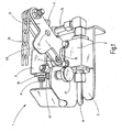
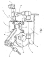
- Fig. 1 and 2 the control unit 1 of the safety device on a device carrier 3 on two ball valves 5 and 7, which are arranged in tandem with coaxial and facing each other rotary spindles 9 at a distance.
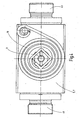
- the Fig. 3 illustrates the hydraulic circuit of the control unit 1 with a supply input P in conjunction with the ball valve 5, a line 13 to a Brake output V and a line 15 from the brake output V to the second ball valve 7 and the line 11th
- the spindles 9 of the ball valves 5 and 7 are connected to each other by means of an actuating lever 17 to rotate, which formed as a double lever and in Fig. 1 in the first switching state of the control unit corresponding pivot position and in Fig. 2 is shown in the position corresponding to the second switching state, in which an emergency braking is triggered.
- the ball valves 5 and 7 are in the in Fig. 1 biased, by means of coil springs 19. These are, as most clearly Fig. 4 can be seen, at the outlet end of the respective spindle 9 wound around them such that a torque acts on the spindles, which the actuating lever 17 in the in Fig. 1 pretensions shown pivot position.
- tension member 21 in the form of a link chain, which is anchored to the towing vehicle (not shown), pivots the actuating lever 17 against the bias in the in Fig. 2 shown pivot position when the tension member 21 tightens the distance to the towing vehicle and brings the spindles 9 of the ball valves 5, 7 in the switching position corresponding to the second switching state (emergency braking).
- control unit 1 is in the first switching state, corresponding to the normal driving operation, in which via the brake hose, not shown from the towing vehicle brake pressure from the supply input P forth on the ball valve located in the open position 5 to the brake output V and thus to the brake system of the trailer can be forwarded.
- the outflow of pressurized fluid from the hydraulic accumulator 4 is blocked by the ball valve 7 located in the blocking position.
- the ball valve 7 forms a check valve 25 in the blocking position, which, when the pressure at the brake output V (lines 13 and 15) is higher than the pressure in the hydraulic accumulator 4, is pressure-actuatable in order to charge the hydraulic accumulator 4.
- the ball valve 5 prevents the connection from the supply input P to the line 13 and thus to the brake output V.
- the second ball valve 7 connects the hydraulic accumulator 4 via the line 15 to the brake output V. so that the trailer is secured by emergency braking. If in this state the brake hose leading from the towing vehicle to the supply input P of the control unit 1 is not torn off, the hydraulic accumulator 4 can be recharged or charged from the towing vehicle via the additional check valve 27 assigned to the ball valve 5, for example, to perform an initial start-up of the trailer after maintenance, even when the safety device is in the activated state.
- the Fig. 5 to 7 clarify the construction of the ball valves 5, 7, which are provided with an integrated check valve 25, 27. It shows the Fig. 5 the side of the exit of the spindle 9 without the associated, in Fig. 4 visible spiral spring 19, so that in Fig. 5 the underlying under the coil spring 19 rotation limitation is visible, which consists of connected to the spindle 9 Begrenzersay 29 and stop 31.
- the switching ball 33 is not rigidly connected to the spindle 9, but from the spindle 9 via a cam slot 35 (FIGS. Fig. 6 ) rotatable.
- a cam slot 35 FIGS. Fig. 6
- Fig. 1 and 2 show a locking device for releasably locking the operating lever 17 in the second switching state corresponding pivot position.
- the latching device has in the lever 17 a detent in the form of a bore 45 and the device carrier 3 on a latch member 47 which is biased by a spring, not shown, in the advanced latch position, from which it is manually retractable against the spring force by a handle 51.
- On the actuating lever 17 is a slightly inclined control surface 49, at which the tip of the locking member 47 upon pivoting of the lever 17 in Fig. 1 and 2 starts to the left until the locking member 47 is incident in the bore 45 and thereby the lever 17 in the in Fig. 2 locked position shown corresponding to the second switching state.
- the lever 17 pivots in the in Fig. 1 shown pivot position under the influence of a torque generating coil spring 19 back.
Landscapes
- Engineering & Computer Science (AREA)
- Transportation (AREA)
- Mechanical Engineering (AREA)
- Regulating Braking Force (AREA)
- Valves And Accessory Devices For Braking Systems (AREA)
- Braking Systems And Boosters (AREA)
Description
- Die Erfindung betrifft eine Sicherheitseinrichtung für Anhänger von vorzugsweise landwirtschaftlich nutzbaren Zugfahrzeugen, die mit einem hydraulisch betätigbaren Bremssystem versehen sind, mit einer Steuereinheit, die einen Versorgungseingang für vom Zugfahrzeug mit Bremsdruck zuzuführendem Druckfluid, einen Bremsausgang in Verbindung mit zumindest einem Bremszylinder des Anhängers, einen Hydrospeicher und eine schaltbare Ventilanordnung aufweist, die aus einem ersten Schaltzustand, in dem sie den Versorgungseingang mit dem Bremsausgang verbindet, mittels eines Zuggliedes, das bei Vergrößerung des Abstandes zwischen Zugfahrzeug und Anhänger spannbar ist, in einen zweiten Schaltzustand bringbar ist, in dem sie die Verbindung vom Bremsausgang zum Versorgungseingang hin unterbindet und den Hydrospeicher mit dem Bremsausgang verbindet.
- Sicherheitseinrichtungen dieser Art sind bekannt. Die französische Patentveröffentlichung
2 501 604 - Beim Stand der Technik sind die bei der Steuereinheit benutzten Ventile als Schieberventile ausgebildet. Da derartige Ventile konstruktionsbedingt mit einer Leckage behaftet sind, kommt es zu einem Absinken des vom Hydrospeicher zur Verfügung gestellten Bremsdruckes und damit nach gewisser Zeit zu einem Verlust der Bremswirkung mit entsprechender Gefährdung durch den nunmehr ungesicherten Anhänger.
- Im Hinblick auf diese Problematik stellt sich die Erfindung die Aufgabe, eine Sicherheitseinrichtung zur Verfügung zu stellen, die demgegenüber eine erhöhte Betriebssicherheit bietet.
- Erfindungsgemäß ist diese Aufgabe durch eine Sicherheitseinrichtung gelöst, die die Merkmale des Patentanspruches 1 in seiner Gesamtheit aufweist.
- Entsprechend dem kennzeichnenden Teil des Anspruches 1 besteht eine wesentliche Besonderheit der Erfindung darin, dass anstelle von Schieberventilen in der Ventilanordnung Kugelhähne vorgesehen sind, die mechanisch miteinander gekoppelt sind, wobei ein Kugelhahn die Verbindung zwischen Versorgungseingang und Bremsausgang der Steuereinheit und der zweite Kugelhahn die Verbindung zwischen Bremsausgang und Hydrospeicher steuert und wobei die Kugelhähne zum Auslösen einer Notbremsung durch Anspannen des Zuggliedes gegen eine angreifende Vorspannung drehbetätigt sind. Da bei Kugelhähnen die Schaltkugel in ihrem Sitz bei geschlossenem Kugelhahn leckagefrei sitzt, besteht keine Gefahr des Druckabbaues, so dass der Anhänger nach Auslösung einer Notbremsung im gesicherten Zustand verbleibt. Dadurch, dass darüber hinaus erfindungsgemäß zumindest der dem Hydrospeicher zugeordnete zweite Kugelhahn mit einem Rückschlagventil versehen ist, das für einen Fluidstrom vom Bremsausgang zum Hydrospeicher hin druckbetätigbar ist, ist sichergestellt, dass der Hydrospeicher während des Normalbetriebes über den vom Zugfahrzeug zum Versorgungsanschluss der Steuereinheit führenden Bremsschlauch aufgeladen wird und dadurch sichergestellt ist, dass für eine Notbremsung der Bremsdruck zur Verfügung steht.
- Vorzugsweise ist auch der erste Kugelhahn mit einem Rückschlagventil versehen, das bei der zweiten Schaltposition für einen Fluidstrom vom Versorgungseingang zum Bremsausgang hin druckbetätigbar ist. Dadurch kann, auch wenn die Sicherheitseinrichtung ausgelöst und der Anhänger durch den vom Hydrospeicher gelieferten Bremsdruck gebremst ist, der Hydrospeicher über den Bremsschlauch vom Zugfahrzeug her aufgeladen werden, beispielsweise für eine anfängliche Inbetriebnahme des Anhängers, etwa nach Wartungsarbeiten mit entleerter Bremsanlage.
- Bei besonders bevorzugten Ausführungsbeispielen sind Kugelhähne vorgesehen, bei denen zur Bildung eines integrierten Rückschlagventils die Schaltkugel gegen eine Federkraft aus ihrer an einem Sitz anliegenden Schließposition abhebbar ist. Dadurch, dass die Schaltkugel der Kugelhähne nicht nur die leckagefreie Sperrfunktion übernimmt, sondern auch eine gesteuerte Rückströmung ermöglicht, verringern sich die Anzahl der Funktionskomponenten und damit der Schaltungsaufwand der Steuereinrichtung, was wiederum eine besonders kompakte Bauweise ermöglicht.
- Um die Kugelhähne in die dem ersten Schaltzustand entsprechende Schaltposition vorzuspannen, kann zumindest eine Spiralfeder vorgesehen sein, die die Spindel des betreffenden Kugelhahnes umgibt und die Spindel mit Drehmoment beaufschlagt. Mit geringem erforderlichen Bauraum ist dadurch ein Drehmoment ausreichender Stärke erreichbar. Aufgrund der kompakten Bauweise lassen sich ohne Schwierigkeiten an jedem der beiden Kugelhähne eine Spiralfeder anordnen.
- Mit besonderem Vorteil kann die Anordnung so getroffen sein, dass die Kugelhähne mit zueinander koaxialer Spindel und einen Abstand zwischen sich freilassend angeordnet sind und dass innerhalb dieses Abstandes ein Betätigungshebel mit beiden Spindeln drehfest verbunden ist, an dessen freiem Ende das Zugglied angreift.
- Hinsichtlich der Gestaltung einer Einrichtung zum lösbaren Verrasten der in der zweiten Schaltposition befindlichen Kugelhähne kann die Anordnung mit Vorteil so getroffen sein, dass am Betätigungshebel eine Raste und ein dieser zugeordnetes, zum Einfallen in die Raste vorgespanntes Riegelglied vorgesehen sind, das an einem Träger der Kugelhähne gelagert und zum Lösen der Verrastung manuell aus der Raste aushebbar ist. Dadurch bleibt der durch die Sicherheitseinrichtung gebremste Anhänger so lange im gebremsten, gesicherten Zustand, bis die Verrastung des Betätigungshebels gelöst wird. Somit kann bei Bedarf der Anhänger auch ohne Verbindung zum Zugfahrzeug gehandhabt werden. Durch manuelles Betätigen des Betätigungshebels und Wiederherstellen der Verrastung ist der Anhänger wiederum in den gebremsten Zustand überführbar. Die Sicherheitseinrichtung kann somit in Zusatzfunktion auch eine mechanische Handbremse des Anhängers unterstützen oder ersetzen, zumal die letztgenannten Vorgänge, ohne Verbindung zum Zugfahrzeug, mehrfach wiederholt werden können, da dank der ohne Leckageverlust arbeitenden Ventilanordnung gespeicherte Bremsenergie im Hydrospeicher zur Verfügung steht.
- Nachstehend ist die Erfindung anhand eines in der Zeichnung dargestellten Ausführungsbeispieles im Einzelnen erläutert. Es zeigen:
- Fig. 1
- eine perspektivische Schrägansicht der Steuereinheit eines Ausführungsbeispieles der erfindungsgemäßen Sicherheitsein- richtung, dargestellt im ersten Schaltzustand, wobei ein zuge- höriger Hydrospeicher nicht dargestellt ist;
- Fig. 2
- eine der
Fig. 1 entsprechende Ansicht, wobei jedoch der zweite Schaltzustand dargestellt ist; - Fig. 3
- eine Symboldarstellung der hydraulischen Schaltung der Steuereinheit;
- Fig. 4
- eine vergrößert gezeichnete Draufsicht eines Kugelhahnes der Steuereinheit;
- Fig. 5
- eine der
Fig. 4 ähnliche, jedoch demgegenüber in kleinerem Maßstab gezeichnete Draufsicht eines Kugelhahnes ohne die inFig. 4 gezeigte Spiralfeder; - Fig. 6
- eine teils in Seitenansicht teils entsprechend der Schnittlinie VI-VI von
Fig. 5 geschnitten gezeichnete Darstellung des Ku- gelhahnes, wobei die Offenstellung des Hahnes dargestellt ist, und - Fig. 7
- eine der
Fig. 6 ähnliche Darstellung, ohne Spiralfeder und wobei die Schaltkugel gegenüberFig. 6 um 90° Grad ver- dreht ist. - Gemäß
Fig. 1 und2 weist die Steuereinheit 1 der Sicherheitseinrichtung auf einem Geräteträger 3 zwei Kugelhähne 5 und 7 auf, die in Tandemanordnung mit koaxialen und einander zugekehrten Drehspindeln 9 in einem Abstand voneinander angeordnet sind. Ein unterhalb des Trägers 3 befindlicher Hydrospeicher 4 (Fig. 3 ), beim Ausführungsbeispiel in Form eines Blasenspeichers (0,75 I/60 Bar), der inFig. 1 und2 nicht sichtbar ist, ist über eine Leitung 11 mit dem Kugelhahn 7 verbunden. DieFig. 3 verdeutlicht die hydraulische Schaltung der Steuereinheit 1 mit einem Versorgungseingang P in Verbindung mit dem Kugelhahn 5, einer Leitung 13 zu einem Bremsausgang V und einer Leitung 15 vom Bremsausgang V zum zweiten Kugelhahn 7 und der Leitung 11. - Die Spindeln 9 der Kugelhähne 5 und 7 sind mittels eines Betätigungshebels 17 miteinander auf Drehung verbunden, der als Doppelhebel ausgebildet und in
Fig. 1 in der dem ersten Schaltzustand der Steuereinheit entsprechenden Schwenkstellung und inFig. 2 in der dem zweiten Schaltzustand entsprechenden Stellung dargestellt ist, bei der eine Notbremsung ausgelöst ist. Die Kugelhähne 5 und 7 sind in die inFig. 1 gezeigte Drehstellung vorgespannt, und zwar mittels Spiralfedern 19. Diese sind, wie am deutlichsten ausFig. 4 zu ersehen ist, am Austrittsende der jeweiligen Spindel 9 derart um sie gewunden, dass ein Drehmoment an den Spindeln wirkt, die den Betätigungshebel 17 in die inFig. 1 dargestellte Schwenklage vorspannt. Ein am freien Ende des Betätigungshebels 17 angebrachtes Zugglied 21 in Form einer Gliederkette, die am (nicht gezeigten) Zugfahrzeug verankert ist, schwenkt den Betätigungshebel 17 gegen die Vorspannung in die inFig. 2 gezeigte Schwenkposition, wenn sich das Zugglied 21 bei Vergrößerung des Abstandes zum Zugfahrzeug anspannt und bringt die Spindeln 9 der Kugelhähne 5, 7 in die Schaltposition, die dem zweiten Schaltzustand (Notbremsung) entspricht. - Bei der Darstellung von
Fig. 3 befindet sich die Steuereinheit 1 in dem ersten Schaltzustand, entsprechend dem normalen Fahrbetrieb, bei dem über den nicht dargestellten Bremsschlauch vom Zugfahrzeug her Bremsdruck vom Versorgungseingang P her über den in Offenstellung befindlichen Kugelhahn 5 zum Bremsausgang V und damit zur Bremsanlage des Anhängers weiterleitbar ist. Gleichzeitig ist durch den in der Sperrstellung befindlichen Kugelhahn 7 der Abfluss von Druckfluid aus dem Hydrospeicher 4 gesperrt. - Wie bereits erwähnt, bildet der Kugelhahn 7 jedoch bei der Sperrstellung ein Rückschlagventil 25, das, wenn der Druck am Bremsausgang V (Leitungen 13 und 15) höher ist als der Druck im Hydrospeicher 4, druckbetätigbar ist, um den Hydrospeicher 4 zu laden.
- Wird durch Spannen des Zuggliedes 21 die Steuereinheit 1 in den zweiten Schaltzustand überführt, unterbindet der Kugelhahn 5 die Verbindung vom Versorgungseingang P zur Leitung 13 und damit zum Bremsausgang V. Gleichzeitig verbindet der zweite Kugelhahn 7 den Hydrospeicher 4 über die Leitung 15 mit dem Bremsausgang V, so dass der Anhänger durch Notbremsung gesichert ist. Wenn bei diesem Zustand der Bremsschlauch, der vom Zugfahrzeug zum Versorgungseingang P der Steuereinheit 1 führt, nicht abgerissen ist, kann über das dem Kugelhahn 5 zugeordnete weitere Rückschlagventil 27 auch bei geschlossenem Kugelhahn 5 der Hydrospeicher 4 vom Zugfahrzeug her nachgeladen oder aufgeladen werden, beispielsweise, um eine anfängliche Inbetriebnahme des Anhängers nach Wartungsarbeiten vorzunehmen, selbst wenn sich die Sicherheitseinrichtung im aktivierten Zustand befindet.
- Die
Fig. 5 bis 7 verdeutlichen die Bauweise der Kugelhähne 5, 7, die mit einem integrierten Rückschlagventil 25, 27 versehen sind. Dabei zeigt dieFig. 5 die Seite des Austrittes der Spindel 9 ohne die zugehörige, inFig. 4 sichtbare Spiralfeder 19, so dass inFig. 5 die unter der Spiralfeder 19 liegende Drehbegrenzung sichtbar ist, die aus mit der Spindel 9 verbundener Begrenzerscheibe 29 und Anschlag 31 besteht. Um innerhalb des Kugelhahnes 5, 7 jeweils ein integriertes Rückschlagventil zu bilden, ist die Schaltkugel 33 mit der Spindel 9 nicht starr verbunden, sondern von der Spindel 9 über einen Mitnehmerschlitz 35 (Fig. 6 ) drehbar. Bei der inFig. 7 gezeigten Schließstellung ist daher die Schaltkugel 33 von ihrem Sitz 37, an dem sie bei der Schließstellung leckagefrei dichtend anliegt, gegen die Wirkung einer Ventilfeder 39 abhebbar, so dass ein druckbetätigbares Rückschlagventil gebildet ist, das für einen Durchstrom vom Anschluss 41 zum Anschluss 43 hin druckbetätigbar ist. -
Fig. 1 und2 zeigen eine Rasteinrichtung zur lösbaren Verrastung des Betätigungshebels 17 in der dem zweiten Schaltzustand entsprechenden Schwenkstellung. Die Rasteinrichtung weist im Hebel 17 eine Raste in Form einer Bohrung 45 und am Geräteträger 3 ein Riegelglied 47 auf, das durch eine nicht dargestellte Feder in die vorgeschobene Riegelstellung vorgespannt ist, aus der es gegen die Federkraft durch eine Handhabe 51 manuell zurückziehbar ist. Am Betätigungshebel 17 befindet sich eine leicht schräg verlaufende Steuerfläche 49, an der die Spitze des Riegelgliedes 47 bei Schwenken des Hebels 17 inFig. 1 und2 nach links anläuft, bis das Riegelglied 47 in die Bohrung 45 einfällt und dadurch den Hebel 17 in der inFig. 2 gezeigten Stellung verrastet, die dem zweiten Schaltzustand entspricht. Bei Zurückziehen des Riegelgliedes 47 mittels der Handhabe 51 schwenkt der Hebel 17 in die inFig. 1 gezeigte Schwenkstellung unter Einfluss der ein Drehmoment erzeugenden Spiralfeder 19 zurück.
Claims (7)
- Sicherheitseinrichtung für Anhänger von vorzugsweise landwirtschaftlich nutzbaren Zugfahrzeugen, die mit einem hydraulisch betätigbaren Bremssystem versehen sind, mit einer Steuereinheit (1), die einen Versorgungseingang (P) für vom Zugfahrzeug mit Bremsdruck zuzuführendem Druckfluid, einen Bremsausgang (V) in Verbindung mit zumindest einem Bremszylinder des Anhängers, einen Hydrospeicher (4) und eine schaltbare Ventilanordnung (5, 7) aufweist, die aus einem ersten Schaltzustand, in dem sie den Versorgungseingang (P) mit dem Bremsausgang (V) verbindet, mittels eines Zuggliedes (21), das bei Vergrößerung des Abstandes zwischen Zugfahrzeug und Anhänger spannbar ist, in einen zweiten Schaltzustand bringbar ist, in dem sie die Verbindung vom Bremsausgang (V) zum Versorgungseingang (P) hin unterbindet und den Hydrospeicher (4) mit dem Bremsausgang (V) verbindet, dadurch gekennzeichnet, dass die Ventilanordnung zwei mechanisch gekoppelte Kugelhähne (5, 7) aufweist, die durch das Spannen des Zuggliedes (21) gegen an ihnen wirksame Vorspannung aus ihrer dem ersten Schaltzustand entsprechenden ersten Schaltposition in die andere, zweite Schaltposition drehbetätigbar sind, dass der eine Kugelhahn (5) die Verbindung zwischen Versorgungseingang (P) und Bremsausgang (V) und der zweite Kugelhahn (7) die Verbindung zwischen Bremsausgang (V) und Hydrospeicher (4) steuert, und dass zumindest der zweite Kugelhahn (7) mit einem Rückschlagventil (25) versehen ist, das für einen Fluidstrom vom Bremsausgang (V) zum Hydrospeicher (4) hin druckbetätigbar ist.
- Sicherheitssystem nach Anspruch 1, dadurch gekennzeichnet, dass auch der erste Kugelhahn (5) mit einem Rückschlagventil (27) versehen ist, das bei der zweiten Schaltposition für einen Fluidstrom vom Versorgungseingang (P) zum Bremsausgang (V) hin druckbetätigbar ist.
- Sicherheitseinrichtung nach Anspruch 1 oder 2, dadurch gekennzeichnet, dass Kugelhähne (5, 7) vorgesehen sind, bei denen zur Bildung eines integrierten Rückschlagventils (25, 27) die Schaltkugel (33) gegen eine Federkraft (39) aus ihrer an einem Sitz (37) anliegenden Schließposition abhebbar ist.
- Sicherheitseinrichtung nach einem der Ansprüche 1 bis 3, dadurch gekennzeichnet, dass eine Einrichtung (45, 47) zum lösbaren Verrasten der in die zweite Schaltposition drehbetätigten Kugelhähne (5, 7) vorgesehen ist.
- Sicherheitseinrichtung nach einem der Ansprüche 1 bis 4, dadurch gekennzeichnet, dass zum Erzeugen der Vorspannung, die die Kugelhähne (5, 7) in die dem ersten Schaltzustand entsprechende Schaltposition vorspannt, zumindest eine Spiralfeder (19) vorgesehen ist, die die Spindel (9) des betreffenden Kugelhahnes (5, 7) umgibt und die Spindel (9) mit Drehmoment beaufschlagt.
- Sicherheitseinrichtung nach einem der Ansprüche 1 bis 5, dadurch gekennzeichnet, dass die Kugelhähne (5, 7) mit zueinander koaxialen Spindeln (9) und einen Abstand zwischen sich freilassend angeordnet sind und dass innerhalb dieses Abstandes ein Betätigungshebel (17) mit beiden Spindeln (9) drehfest verbunden ist, an dessen freiem Ende das Zugglied (21) angreift.
- Sicherheitseinrichtung nach Anspruch 6, dadurch gekennzeichnet, dass die Einrichtung zum lösbaren Verrasten der Kugelhähne (5, 7) am Betätigungshebel (17) eine Raste (45) und ein dieser zugeordnetes, zum Einfallen in die Raste (45) vorgespanntes Riegelglied (47) aufweist, das an einem Träger (3) der Kugelhähne (5, 7) gelagert und zum Lösen der Verrastung manuell aus der Raste (45) aushebbar ist.
Applications Claiming Priority (1)
| Application Number | Priority Date | Filing Date | Title |
|---|---|---|---|
| DE102010010836A DE102010010836A1 (de) | 2010-03-10 | 2010-03-10 | Sicherheitseinrichtung für Anhänger |
Publications (2)
| Publication Number | Publication Date |
|---|---|
| EP2364890A1 EP2364890A1 (de) | 2011-09-14 |
| EP2364890B1 true EP2364890B1 (de) | 2012-03-21 |
Family
ID=44141026
Family Applications (1)
| Application Number | Title | Priority Date | Filing Date |
|---|---|---|---|
| EP11001357A Active EP2364890B1 (de) | 2010-03-10 | 2011-02-18 | Sicherheitseinrichtung für Anhänger |
Country Status (3)
| Country | Link |
|---|---|
| EP (1) | EP2364890B1 (de) |
| AT (1) | ATE550233T1 (de) |
| DE (1) | DE102010010836A1 (de) |
Families Citing this family (1)
| Publication number | Priority date | Publication date | Assignee | Title |
|---|---|---|---|---|
| GB2555906B (en) * | 2016-08-19 | 2021-09-29 | Innealtoireacht Ui Loinsigh Teo | A Trailer Breakaway Brake System |
Family Cites Families (5)
| Publication number | Priority date | Publication date | Assignee | Title |
|---|---|---|---|---|
| GB698319A (en) * | 1951-07-31 | 1953-10-14 | Westinghouse Brake & Signal | Improvements relating to tractor-trailer fluid pressure braking apparatus |
| US2834437A (en) * | 1956-08-22 | 1958-05-13 | Berryman O Davids | Automatic brake applicator |
| DE3008067A1 (de) * | 1980-03-03 | 1981-09-24 | G.L. Rexroth Gmbh, 8770 Lohr | Ausloesevorrichtung fuer ein abreissventil |
| FR2501604A1 (fr) | 1981-03-10 | 1982-09-17 | Henrion Ets | Dispositif de securite de freinage pour une remorque de tracteur agricole |
| GB9904290D0 (en) * | 1999-02-25 | 1999-04-21 | Ford New Holland Nv | Fail safe braking system |
-
2010
- 2010-03-10 DE DE102010010836A patent/DE102010010836A1/de not_active Withdrawn
-
2011
- 2011-02-18 EP EP11001357A patent/EP2364890B1/de active Active
- 2011-02-18 AT AT11001357T patent/ATE550233T1/de active
Also Published As
| Publication number | Publication date |
|---|---|
| DE102010010836A1 (de) | 2011-09-15 |
| ATE550233T1 (de) | 2012-04-15 |
| EP2364890A1 (de) | 2011-09-14 |
Similar Documents
| Publication | Publication Date | Title |
|---|---|---|
| DE102004045988B3 (de) | Anzeige zur Signalisierung der Nichtverriegelung einer klappbaren Rückenlehne eines Kraftfahrzeugsitzes | |
| EP3515770B1 (de) | Parkbrems-ventileinrichtung zur ansteuerung einer federspeicherfeststellbremse | |
| EP2836406B1 (de) | Luftaufbereitungsanlage für die druckluftversorgung von nutzkraftfahrzeugen | |
| DE102012107203B4 (de) | Pneumatische Bremseinrichtung eines Fahrzeugs mit vom Parkbremsventil zwangsgesteuerter Interlock-Einrichtung | |
| DE102016210874B4 (de) | Vorrichtung zum Betätigen einer Parksperre eines Automatikgetriebes, sowie Parksperreneinrichtung für ein solches Automatikgetriebe | |
| DE102021111206A1 (de) | Automatische Zugkupplung und Verfahren zum Entkuppeln einer automatischen Zugkupplung | |
| DE1218891B (de) | Druckmittelbremsanlage fuer Fahrzeuge, insbesondere Kraftfahrzeuge | |
| DE102009036783B4 (de) | Nothahn, Türbetätigungsvorrichtung, Fahrzeugtüranlage, Fahrzeug und Verfahren zum Betreiben einer Fahrzeugtüranlage | |
| EP0830997B1 (de) | Energieversorgungseinrichtung für Druckluft-Bremsanlagen von Fahrzeugen | |
| EP2364890A1 (de) | Sicherheitseinrichtung für Anhänger | |
| DE2500903A1 (de) | Steuerungssystem fuer eine bremse | |
| DE102015106171A1 (de) | Hydraulisch betätigbare Pneumatikventileinrichtung | |
| DE2919539C2 (de) | Hydraulische Anhängerbremsanlage | |
| DE2546557C2 (de) | Handbremsventil | |
| DE3045455C2 (de) | Hydraulische Anhänger-Bremsanlage für Nutzfahrzeuge | |
| WO2006084445A2 (de) | Tür mit türbremse | |
| DE3630892C2 (de) | ||
| DE2339397C3 (de) | Zweileitungs-Druckluftbremsanlage für Anhängerfahrzeuge, insbesondere Zweikreis-Bremsanlage | |
| DE102013010031A1 (de) | Kupplungskopfeinheit für ein Nutzfahrzeug und Verfahren zum Ankoppeln einer Versorgungsleitung und einer Steuerleitung an eine pneumatisch betriebene Bremsanlage | |
| DE102006035140B3 (de) | Schaltungsanordnung für eine Druckmittelbetätigung einer Tür | |
| DE2501070B2 (de) | Zweileitungs-druckluftbremsanlage fuer kraftfahrzeuge mit anhaenger, mit einem anhaengersteuerventil und einem sperrventil | |
| DE2260714C3 (de) | Vorrichtung zur Verriegelung des hinteren Endes des Kippfahrerhauses eines Lastkraftwagens | |
| AT409112B (de) | Hydraulische anordnung zur betätigung von beweglichen teilen an fahrzeugen, und vorspannventil für diese anordnung | |
| DE2461712C2 (de) | Hydraulische drehvorrichtung fuer einen drehpflug | |
| DE2538738A1 (de) | Sperrvorrichtung zum blockieren von fahrzeugen |
Legal Events
| Date | Code | Title | Description |
|---|---|---|---|
| PUAI | Public reference made under article 153(3) epc to a published international application that has entered the european phase |
Free format text: ORIGINAL CODE: 0009012 |
|
| 17P | Request for examination filed |
Effective date: 20110716 |
|
| AK | Designated contracting states |
Kind code of ref document: A1 Designated state(s): AL AT BE BG CH CY CZ DE DK EE ES FI FR GB GR HR HU IE IS IT LI LT LU LV MC MK MT NL NO PL PT RO RS SE SI SK SM TR |
|
| AX | Request for extension of the european patent |
Extension state: BA ME |
|
| GRAP | Despatch of communication of intention to grant a patent |
Free format text: ORIGINAL CODE: EPIDOSNIGR1 |
|
| GRAS | Grant fee paid |
Free format text: ORIGINAL CODE: EPIDOSNIGR3 |
|
| GRAA | (expected) grant |
Free format text: ORIGINAL CODE: 0009210 |
|
| AK | Designated contracting states |
Kind code of ref document: B1 Designated state(s): AL AT BE BG CH CY CZ DE DK EE ES FI FR GB GR HR HU IE IS IT LI LT LU LV MC MK MT NL NO PL PT RO RS SE SI SK SM TR |
|
| REG | Reference to a national code |
Ref country code: GB Ref legal event code: FG4D Free format text: NOT ENGLISH |
|
| REG | Reference to a national code |
Ref country code: CH Ref legal event code: EP |
|
| REG | Reference to a national code |
Ref country code: IE Ref legal event code: FG4D Free format text: LANGUAGE OF EP DOCUMENT: GERMAN |
|
| REG | Reference to a national code |
Ref country code: AT Ref legal event code: REF Ref document number: 550233 Country of ref document: AT Kind code of ref document: T Effective date: 20120415 |
|
| REG | Reference to a national code |
Ref country code: DE Ref legal event code: R096 Ref document number: 502011000006 Country of ref document: DE Effective date: 20120516 |
|
| REG | Reference to a national code |
Ref country code: NL Ref legal event code: VDEP Effective date: 20120321 |
|
| PG25 | Lapsed in a contracting state [announced via postgrant information from national office to epo] |
Ref country code: LT Free format text: LAPSE BECAUSE OF FAILURE TO SUBMIT A TRANSLATION OF THE DESCRIPTION OR TO PAY THE FEE WITHIN THE PRESCRIBED TIME-LIMIT Effective date: 20120321 Ref country code: NO Free format text: LAPSE BECAUSE OF FAILURE TO SUBMIT A TRANSLATION OF THE DESCRIPTION OR TO PAY THE FEE WITHIN THE PRESCRIBED TIME-LIMIT Effective date: 20120621 Ref country code: HR Free format text: LAPSE BECAUSE OF FAILURE TO SUBMIT A TRANSLATION OF THE DESCRIPTION OR TO PAY THE FEE WITHIN THE PRESCRIBED TIME-LIMIT Effective date: 20120321 |
|
| LTIE | Lt: invalidation of european patent or patent extension |
Effective date: 20120321 |
|
| PG25 | Lapsed in a contracting state [announced via postgrant information from national office to epo] |
Ref country code: FI Free format text: LAPSE BECAUSE OF FAILURE TO SUBMIT A TRANSLATION OF THE DESCRIPTION OR TO PAY THE FEE WITHIN THE PRESCRIBED TIME-LIMIT Effective date: 20120321 Ref country code: RS Free format text: LAPSE BECAUSE OF FAILURE TO SUBMIT A TRANSLATION OF THE DESCRIPTION OR TO PAY THE FEE WITHIN THE PRESCRIBED TIME-LIMIT Effective date: 20120321 Ref country code: LV Free format text: LAPSE BECAUSE OF FAILURE TO SUBMIT A TRANSLATION OF THE DESCRIPTION OR TO PAY THE FEE WITHIN THE PRESCRIBED TIME-LIMIT Effective date: 20120321 Ref country code: GR Free format text: LAPSE BECAUSE OF FAILURE TO SUBMIT A TRANSLATION OF THE DESCRIPTION OR TO PAY THE FEE WITHIN THE PRESCRIBED TIME-LIMIT Effective date: 20120622 |
|
| PG25 | Lapsed in a contracting state [announced via postgrant information from national office to epo] |
Ref country code: CY Free format text: LAPSE BECAUSE OF FAILURE TO SUBMIT A TRANSLATION OF THE DESCRIPTION OR TO PAY THE FEE WITHIN THE PRESCRIBED TIME-LIMIT Effective date: 20120321 |
|
| PG25 | Lapsed in a contracting state [announced via postgrant information from national office to epo] |
Ref country code: SE Free format text: LAPSE BECAUSE OF FAILURE TO SUBMIT A TRANSLATION OF THE DESCRIPTION OR TO PAY THE FEE WITHIN THE PRESCRIBED TIME-LIMIT Effective date: 20120321 Ref country code: IS Free format text: LAPSE BECAUSE OF FAILURE TO SUBMIT A TRANSLATION OF THE DESCRIPTION OR TO PAY THE FEE WITHIN THE PRESCRIBED TIME-LIMIT Effective date: 20120721 Ref country code: EE Free format text: LAPSE BECAUSE OF FAILURE TO SUBMIT A TRANSLATION OF THE DESCRIPTION OR TO PAY THE FEE WITHIN THE PRESCRIBED TIME-LIMIT Effective date: 20120321 Ref country code: RO Free format text: LAPSE BECAUSE OF FAILURE TO SUBMIT A TRANSLATION OF THE DESCRIPTION OR TO PAY THE FEE WITHIN THE PRESCRIBED TIME-LIMIT Effective date: 20120321 Ref country code: CZ Free format text: LAPSE BECAUSE OF FAILURE TO SUBMIT A TRANSLATION OF THE DESCRIPTION OR TO PAY THE FEE WITHIN THE PRESCRIBED TIME-LIMIT Effective date: 20120321 Ref country code: PL Free format text: LAPSE BECAUSE OF FAILURE TO SUBMIT A TRANSLATION OF THE DESCRIPTION OR TO PAY THE FEE WITHIN THE PRESCRIBED TIME-LIMIT Effective date: 20120321 Ref country code: SI Free format text: LAPSE BECAUSE OF FAILURE TO SUBMIT A TRANSLATION OF THE DESCRIPTION OR TO PAY THE FEE WITHIN THE PRESCRIBED TIME-LIMIT Effective date: 20120321 |
|
| PG25 | Lapsed in a contracting state [announced via postgrant information from national office to epo] |
Ref country code: SK Free format text: LAPSE BECAUSE OF FAILURE TO SUBMIT A TRANSLATION OF THE DESCRIPTION OR TO PAY THE FEE WITHIN THE PRESCRIBED TIME-LIMIT Effective date: 20120321 |
|
| PLBE | No opposition filed within time limit |
Free format text: ORIGINAL CODE: 0009261 |
|
| STAA | Information on the status of an ep patent application or granted ep patent |
Free format text: STATUS: NO OPPOSITION FILED WITHIN TIME LIMIT |
|
| PG25 | Lapsed in a contracting state [announced via postgrant information from national office to epo] |
Ref country code: DK Free format text: LAPSE BECAUSE OF FAILURE TO SUBMIT A TRANSLATION OF THE DESCRIPTION OR TO PAY THE FEE WITHIN THE PRESCRIBED TIME-LIMIT Effective date: 20120321 Ref country code: NL Free format text: LAPSE BECAUSE OF FAILURE TO SUBMIT A TRANSLATION OF THE DESCRIPTION OR TO PAY THE FEE WITHIN THE PRESCRIBED TIME-LIMIT Effective date: 20120321 |
|
| 26N | No opposition filed |
Effective date: 20130102 |
|
| REG | Reference to a national code |
Ref country code: DE Ref legal event code: R097 Ref document number: 502011000006 Country of ref document: DE Effective date: 20130102 |
|
| PG25 | Lapsed in a contracting state [announced via postgrant information from national office to epo] |
Ref country code: BG Free format text: LAPSE BECAUSE OF FAILURE TO SUBMIT A TRANSLATION OF THE DESCRIPTION OR TO PAY THE FEE WITHIN THE PRESCRIBED TIME-LIMIT Effective date: 20120621 |
|
| BERE | Be: lapsed |
Owner name: HYDAC ACCESSORIES G.M.B.H. Effective date: 20130228 |
|
| PG25 | Lapsed in a contracting state [announced via postgrant information from national office to epo] |
Ref country code: MC Free format text: LAPSE BECAUSE OF NON-PAYMENT OF DUE FEES Effective date: 20130228 |
|
| PG25 | Lapsed in a contracting state [announced via postgrant information from national office to epo] |
Ref country code: ES Free format text: LAPSE BECAUSE OF FAILURE TO SUBMIT A TRANSLATION OF THE DESCRIPTION OR TO PAY THE FEE WITHIN THE PRESCRIBED TIME-LIMIT Effective date: 20120702 |
|
| REG | Reference to a national code |
Ref country code: IE Ref legal event code: MM4A |
|
| PG25 | Lapsed in a contracting state [announced via postgrant information from national office to epo] |
Ref country code: BE Free format text: LAPSE BECAUSE OF NON-PAYMENT OF DUE FEES Effective date: 20130228 Ref country code: AL Free format text: LAPSE BECAUSE OF FAILURE TO SUBMIT A TRANSLATION OF THE DESCRIPTION OR TO PAY THE FEE WITHIN THE PRESCRIBED TIME-LIMIT Effective date: 20120321 Ref country code: IE Free format text: LAPSE BECAUSE OF NON-PAYMENT OF DUE FEES Effective date: 20130218 |
|
| PG25 | Lapsed in a contracting state [announced via postgrant information from national office to epo] |
Ref country code: MT Free format text: LAPSE BECAUSE OF FAILURE TO SUBMIT A TRANSLATION OF THE DESCRIPTION OR TO PAY THE FEE WITHIN THE PRESCRIBED TIME-LIMIT Effective date: 20120321 |
|
| REG | Reference to a national code |
Ref country code: CH Ref legal event code: PL |
|
| PG25 | Lapsed in a contracting state [announced via postgrant information from national office to epo] |
Ref country code: LI Free format text: LAPSE BECAUSE OF NON-PAYMENT OF DUE FEES Effective date: 20140228 Ref country code: CH Free format text: LAPSE BECAUSE OF NON-PAYMENT OF DUE FEES Effective date: 20140228 |
|
| PG25 | Lapsed in a contracting state [announced via postgrant information from national office to epo] |
Ref country code: SM Free format text: LAPSE BECAUSE OF FAILURE TO SUBMIT A TRANSLATION OF THE DESCRIPTION OR TO PAY THE FEE WITHIN THE PRESCRIBED TIME-LIMIT Effective date: 20120321 |
|
| PG25 | Lapsed in a contracting state [announced via postgrant information from national office to epo] |
Ref country code: TR Free format text: LAPSE BECAUSE OF FAILURE TO SUBMIT A TRANSLATION OF THE DESCRIPTION OR TO PAY THE FEE WITHIN THE PRESCRIBED TIME-LIMIT Effective date: 20120321 |
|
| PG25 | Lapsed in a contracting state [announced via postgrant information from national office to epo] |
Ref country code: MK Free format text: LAPSE BECAUSE OF FAILURE TO SUBMIT A TRANSLATION OF THE DESCRIPTION OR TO PAY THE FEE WITHIN THE PRESCRIBED TIME-LIMIT Effective date: 20120321 Ref country code: HU Free format text: LAPSE BECAUSE OF FAILURE TO SUBMIT A TRANSLATION OF THE DESCRIPTION OR TO PAY THE FEE WITHIN THE PRESCRIBED TIME-LIMIT; INVALID AB INITIO Effective date: 20110218 Ref country code: LU Free format text: LAPSE BECAUSE OF NON-PAYMENT OF DUE FEES Effective date: 20130218 |
|
| GBPC | Gb: european patent ceased through non-payment of renewal fee |
Effective date: 20150218 |
|
| REG | Reference to a national code |
Ref country code: FR Ref legal event code: PLFP Year of fee payment: 6 |
|
| PG25 | Lapsed in a contracting state [announced via postgrant information from national office to epo] |
Ref country code: GB Free format text: LAPSE BECAUSE OF NON-PAYMENT OF DUE FEES Effective date: 20150218 |
|
| PG25 | Lapsed in a contracting state [announced via postgrant information from national office to epo] |
Ref country code: PT Free format text: LAPSE BECAUSE OF FAILURE TO SUBMIT A TRANSLATION OF THE DESCRIPTION OR TO PAY THE FEE WITHIN THE PRESCRIBED TIME-LIMIT Effective date: 20120321 |
|
| REG | Reference to a national code |
Ref country code: FR Ref legal event code: PLFP Year of fee payment: 7 |
|
| REG | Reference to a national code |
Ref country code: FR Ref legal event code: PLFP Year of fee payment: 8 |
|
| PGFP | Annual fee paid to national office [announced via postgrant information from national office to epo] |
Ref country code: IT Payment date: 20190213 Year of fee payment: 9 |
|
| PGFP | Annual fee paid to national office [announced via postgrant information from national office to epo] |
Ref country code: AT Payment date: 20190228 Year of fee payment: 9 |
|
| REG | Reference to a national code |
Ref country code: AT Ref legal event code: MM01 Ref document number: 550233 Country of ref document: AT Kind code of ref document: T Effective date: 20200218 |
|
| PG25 | Lapsed in a contracting state [announced via postgrant information from national office to epo] |
Ref country code: AT Free format text: LAPSE BECAUSE OF NON-PAYMENT OF DUE FEES Effective date: 20200218 |
|
| PG25 | Lapsed in a contracting state [announced via postgrant information from national office to epo] |
Ref country code: IT Free format text: LAPSE BECAUSE OF NON-PAYMENT OF DUE FEES Effective date: 20200218 |
|
| PGFP | Annual fee paid to national office [announced via postgrant information from national office to epo] |
Ref country code: DE Payment date: 20260228 Year of fee payment: 16 |
|
| PGFP | Annual fee paid to national office [announced via postgrant information from national office to epo] |
Ref country code: FR Payment date: 20260213 Year of fee payment: 16 |