EP2364807A1 - Appareil d'alimentation électrique incluant un ventilateur pour le refroidissement de l'air - Google Patents
Appareil d'alimentation électrique incluant un ventilateur pour le refroidissement de l'air Download PDFInfo
- Publication number
- EP2364807A1 EP2364807A1 EP11157498A EP11157498A EP2364807A1 EP 2364807 A1 EP2364807 A1 EP 2364807A1 EP 11157498 A EP11157498 A EP 11157498A EP 11157498 A EP11157498 A EP 11157498A EP 2364807 A1 EP2364807 A1 EP 2364807A1
- Authority
- EP
- European Patent Office
- Prior art keywords
- air
- air path
- fan
- electronic components
- power supply
- Prior art date
- Legal status (The legal status is an assumption and is not a legal conclusion. Google has not performed a legal analysis and makes no representation as to the accuracy of the status listed.)
- Granted
Links
- 238000001816 cooling Methods 0.000 title description 7
- 238000004891 communication Methods 0.000 claims description 4
- 239000000428 dust Substances 0.000 abstract description 68
- 238000007664 blowing Methods 0.000 description 15
- 238000003466 welding Methods 0.000 description 12
- 229910052751 metal Inorganic materials 0.000 description 9
- 239000002184 metal Substances 0.000 description 9
- 230000000694 effects Effects 0.000 description 7
- 230000004913 activation Effects 0.000 description 5
- 239000003990 capacitor Substances 0.000 description 3
- 238000004804 winding Methods 0.000 description 3
- 229910052782 aluminium Inorganic materials 0.000 description 2
- XAGFODPZIPBFFR-UHFFFAOYSA-N aluminium Chemical compound [Al] XAGFODPZIPBFFR-UHFFFAOYSA-N 0.000 description 2
- 230000020169 heat generation Effects 0.000 description 2
- 238000000465 moulding Methods 0.000 description 2
- 239000011347 resin Substances 0.000 description 2
- 229920005989 resin Polymers 0.000 description 2
- 238000009423 ventilation Methods 0.000 description 2
- 238000007667 floating Methods 0.000 description 1
- 239000000463 material Substances 0.000 description 1
- 230000000116 mitigating effect Effects 0.000 description 1
- 238000005192 partition Methods 0.000 description 1
- 230000000630 rising effect Effects 0.000 description 1
- 239000004065 semiconductor Substances 0.000 description 1
- -1 such as a factory Substances 0.000 description 1
Images


Classifications
-
- B—PERFORMING OPERATIONS; TRANSPORTING
- B23—MACHINE TOOLS; METAL-WORKING NOT OTHERWISE PROVIDED FOR
- B23K—SOLDERING OR UNSOLDERING; WELDING; CLADDING OR PLATING BY SOLDERING OR WELDING; CUTTING BY APPLYING HEAT LOCALLY, e.g. FLAME CUTTING; WORKING BY LASER BEAM
- B23K9/00—Arc welding or cutting
- B23K9/10—Other electric circuits therefor; Protective circuits; Remote controls
- B23K9/1006—Power supply
Definitions
- the present invention relates, for example, to a welding power supply apparatus, and particularly to a welding power supply apparatus provided with a fan for air cooling.
- JP 2008-229644A discloses an example of a conventional welding power supply apparatus.
- the power supply apparatus disclosed in the document includes a plurality of electronic components, an air path extending longitudinally, and a fan that blows air draft into this air path.
- the plurality of electronic components are arranged along a side wall of the air path, and the fan is provided at one end of the air path. Air draft that has been blown into the air path by the fan blows out from an exit provided at the other end of the air path, while drawing heat away from the electronic components.
- electronic components that do not tend to generate heat for example, a chip-type semiconductor device and the like
- electronic components that tend to generate heat for example, a transformer, a reactor, and the like
- a transformer, a reactor, and the like are arranged closer to the fan such that they can be efficiently air-cooled.
- the conventional power supply apparatus has a drawback in that any electronic components located away from the fan cannot be easily cooled. It also has a drawback in that the flexibility of arrangement of electronic components is not very high since a plurality of electronic components that are to be cooled need to be arranged in such a manner that those with a higher likelihood of generating heat are arranged closer to the fan. Moreover, during a dust removal operation, compressed air that has been jetted to the interior of the air path tends to directly strike the fan located at one end of the air path, which may cause the fan to be rotated in reverse at high speed and be damaged.
- the above-described conventional power supply apparatus has only a single air path.
- this arrangement significantly affects the temperature and the flow of air draft, resulting in the problem that each of the electronic components cannot be cooled efficiently.
- the power supply apparatus disclosed in the document contains, inside a welding power supply portion, an electronic component that is to be cooled, and a fan is provided in a front surface portion of the welding power supply portion.
- the welding power supply portion is housed in a casing, and thereafter the front surface portion is covered by a front plate.
- the front plate is provided, at its portion located in front of the fan, with an opening for introducing outside air.
- the present invention has been conceived under the foregoing circumstances. Therefore, it is an object of the invention to provide a power supply apparatus capable of solving or mitigating the above-described conventional problems.
- a power supply apparatus including: an air path extending longitudinally; a fan that blows air into the air path in a direction intersecting a longitudinal direction of the air path; and a plurality of electronic components arranged in the longitudinal direction, wherein each of the electronic components is cooled by air passing through the air path.
- the fan is arranged in an intermediate portion of the air path in the longitudinal direction, and two ends of the air path in the longitudinal direction each serve as an exit for air draft.
- the power supply apparatus of the present invention further comprises a heat sink facing the air path, wherein the heat sink is located between the air path and each of the plurality of electronic components.
- the heat sink includes a plurality of fins each extending in the longitudinal direction, and the plurality of fins are aligned with each other with gaps therebetween.
- the power supply apparatus of the present invention further comprises: a first wall (107B) in which an opening facing the air path is formed; a second wall (107A) opposed to the first wall in a first direction that is orthogonal to the longitudinal direction; and a pair of third walls opposed to each other in a second direction that is orthogonal to both the longitudinal direction and the first direction, wherein the air path is surrounded by the first wall, the second wall, and the pair of third walls, the plurality of electronic components are arranged along the second wall, and the fan blows air into the air path through the opening.
- one of the plurality of electronic component is arranged outside the air path.
- one of the plurality of electronic components extends through one of the first wall, the second wall, and the pair of third walls.
- one of the plurality of electronic components is a reactor or a transformer and include a coil portion exposed to the air path.
- the power supply apparatus of the present invention further comprises a plurality of walls, wherein the fan includes a suction port and a discharge port and blows air into the air path from the discharge port, wherein a space that is surrounded by the plurality of walls and that is adjacent to the air path is defined, the plurality of walls include a fan-opposed wall opposed to the suction port, an intake port portion for guiding air outside the space into the space is formed in the fan-opposed wall, and the intake port portion is located in an area displaced, in an in-plane direction of the fan-opposed wall, relative to an area of the fan-opposed wall that is in front of the suction port.
- the discharge port faces an intermediate portion of the air path in the longitudinal direction of the air path
- the fan-opposed wall is parallel to the longitudinal direction
- the intake port portion is located in an area near an end of the fan-opposed wall in the longitudinal direction.
- the intake port portion is located in a vertically intermediate portion of the fan-opposed wall or an area near a vertically upper portion of the fan-opposed wall.
- the power supply apparatus of the present invention further comprises: a front surface portion located at one end of the air path in the longitudinal direction; and a rear surface portion located at the other end of the air path in the longitudinal direction, wherein a ventilating hole portion in communication with the air path is formed in each of the front surface portion and the rear surface portion.
- the power supply apparatus of the present invention further comprises: a second air path separated from the first air path; and a second fan that blows air into the second air path, and the plurality of electronic components are each cooled by air passing through the first air path or air passing through the second air path.
- the second air path is located above the first air path, and has an air volume larger than that of the first fan.
- the power supply apparatus of the present invention further comprises: a first temperature sensor for detecting an internal temperature of the first air path; and a second temperature sensor for detecting an internal temperature of the second air path, wherein the first fan is controlled independently of the second fan in accordance with a signal from the first temperature sensor, and the second fan is controlled independently of the first fan in accordance with a signal from the second temperature sensor.
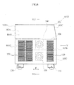
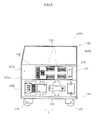
- FIGS. 1 to 3 show one embodiment of a power supply apparatus.
- a power supply apparatus A100 of this embodiment is used, for example, for outputting large current and high voltage necessary for arc welding.
- the power supply apparatus A100 is used in, for example, an environment with a lot of dust, such as a factory.
- the power supply apparatus A100 includes a base member 101, a casing cover 102, various electronic components 103 constituting a power circuit, a heat sink 105, a first parting plate 106, two second parting plates 107A and 107B, and a cooling fan 108.
- a hollow air path 109 is provided that is surrounded by part of the base member 101, part of the first parting plate 106, and the second parting plates 107A and 107B.
- the air path 109 extends longitudinally in the front-rear direction of the power supply apparatus A100 (hereinafter, referred to as "F direction").
- a layout space B101 for the electronic components 103 and a layout space B102 for the fan 108 that are surrounded by part of the base member 101, part of the casing cover 102, part of the first parting plate 106, and the second parting plates 107A and 107B are provided in the apparatus outward of the air path 109.
- the base member 101 is an elongated rectangular plate member that is elongated in the F direction.
- a plurality of wheels 110 are pivotally attached to the under surface of the base member 101 via brackets. The wheels 110 allow the base member 101 to move on a floor surface.
- the second parting plates 107A and 107B are arranged so as to be opposed to each other with a predetermined interval.
- the casing cover 102 is made of, for example, metal and serves to protect the interior of the apparatus.
- the casing cover 102 has the shape of a box that is removable from the base member 101, and includes two side surface portions 102A and 102B forming vertical planes along two lateral sides of the base member 101, and a front surface portion 102C and a rear surface portion 102D forming vertical planes along the front end and the rear end, respectively, of the base member 101.
- Intake port portions 120 for guiding outside air into the layout space B102 for the fan 108 are provided in areas near two ends, in the F direction, of one of the side surface portions, namely, the side surface portion 102A.
- the intake port portions 120 are each formed by many slit holes having a relatively small size.
- the areas of the front surface portion 102C and the rear surface portion 102D that correspond to the air path 109 are each provided with ventilating hole portions 121 for guiding air draft from the air path 109 to the outside.
- the ventilating hole portions 121 are each formed by many holes having a relatively large size for better ventilation.
- the electronic components 103 tend to generate heat during operation, and may be, for example, electronic components constituting a power circuit, such as a switching element, a diode and a capacitor, or also may be other electronic components such as a transformer and a reactor.
- the electronic components 103 are directly attached to the heat sink 105 through the second partingplate 107A. Accordingly, heat fromeach of the electronic components 103 is quickly conducted to the heat sink 105.
- the heat sink 105 is a heat dissipating member made of, for example, aluminum, and includes a base 150 fixed to the second parting plate 107A, and a plurality of vertically aligned fins 151 extending from the base 150 in the F direction.
- the electronic components 103 are directly attached via screws (not shown) or the like to part of the base 150 that is opposed to the second parting plate 107A.
- the plurality of fins 151 are portions that efficiently dissipate the heat conducted from the base 150 into the air, and have an increased surface area to achieve an improved heat dissipating effect.
- the heat sink 105 has approximately the same size as that of the second parting plate 107A, and a longitudinal dimension extending approximately the entire length of the air path 109. In this embodiment, the heat sink 105 is also cooled. Note that the size of the heat sink may be smaller than that of the second parting plate 107A.
- the first parting plate 106 is made of, for example, metal and serves to divide the internal space of the apparatus into an upper space and a lower space.
- the first parting plate 106 has a rectangular shape having approximately the same size as that of the base member 101, and is horizontally arranged in a vertically intermediate position of the casing cover 102.
- the first parting plate 106 forms the top wall of the lower space including the layout space B101 for the electronic components 103, the layout space B102 for the fan 108, the air path 109 and the like.
- electronic components and the like are provided in the upper space as well.
- the second parting plates 107A and 107B are made of metal, for example, and serves to divide the lower space inside the apparatus into spaces such as the layout space B101 for the electronic components 103, the layout space B102 for the fan 108, and the air path 109.
- the second parting plates 107A and 107B have a dimension in the F direction that is approximately the same as that of the base member 101, and are arranged perpendicularly to the base member 101 and the first parting plate 106.
- the second parting plates 107A and 107B form the vertical walls of spaces such as the layout space B101 for the electronic components 103, the layout space B102 for the fan 108, and the air path 109.
- the second parting plate 107A is provided with a rectangular window 170 for causing part of the base 150 of the heat sink 105 to be exposed to the layout space B101 and allowing the electronic components to be attached to that part.
- the rectangular window 170 is closed by the base 150.
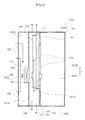
- An opening 171 for allowing the fan 108 to face the air path 109 is provided in an intermediate portion in the F direction of the second parting plate 107B (see FIG. 3 ).
- the fan 108 is of the axial flow type where a plurality of blades and an electric motor are integrated, and includes a suction port 180 and a discharge port 181 for air on two axial ends of its electric motor.
- the fan 108 is arranged such that the discharge port 181 coincides with the opening 171 of the second parting plate 107B.
- the fan 108 is arranged in a longitudinally intermediate portion of the air path 109, and the discharge port 181 is located so as to face the air path 109. Consequently, the blowing direction of the fan 108 is a direction intersecting the longitudinal direction of the air path 109 in the horizontal plane.
- the suction port 180 is located in the layout space B102, and is opposed to the side surface portion 102A with a predetermined interval. Accordingly, the side surface portion 102A is a fan-opposed wall, which is opposed to the suction port 180.
- the intake port portion 120 is not provided in an area of the side surface portion 102A that is in front of the suction port 180. In other words, the suction port 180 is located a certain distance away from the intake port portions 120 located near two ends of the side surface portion 102A in the F direction.
- the air path 109 air-cools the heat sink 105 using air draft from the fan 108, and guides that air draft to its two ends in the longitudinal direction.
- the air path 109 is surrounded by the secondpartingplates 107A and 107B serving as apair of vertical walls that are opposed to each other in the width direction, as well as by part of the first parting plate 106 and part of the base member 101 serving as the top wall and the bottom wall that are vertically opposed to each other, and is formed in a shape having a rectangular cross section.
- the two ends of the air path 109 in the longitudinal direction each serve as an exit 190 from which air draft blows out.
- the air draft that has been blown from the fan 108 into the air path 109 strikes the fins 151, and is split into two air streams flowing to the two ends of the air path 109 in the longitudinal direction. Then, the air streams blow out from the exits 190, while drawing a large amount of heat away from the fins 151.
- the distance for which the air draft flows from the fan 108 to each of the exits 190 within the air path 109 is about half the overall length of the air path 109, and the air draft is quickly discharged to the outside. This allows the electronic components 103 to be efficiently cooled via the heat sink 105.
- the air draft blowing out from the exits 190 quickly blows to the outside through the ventilating hole portions 121 provided in the front surface portion 102C and the rear surface portion 102D of the casing cover 102.
- a plurality of electronic component 103 generate heat as the power supply apparatus A100 outputs large current and high voltage for welding, resulting in an increase in the temperature of the power supply apparatus A100.
- the heat of each of the electronic components 103 is conducted into the air in the layout space B101, and is also directly conducted to the heat sink 105.
- the heat generated in each of the electronic components 103 is efficiently conducted to the heat sink 105 since the metal constituting the material of the heat sink 105 has a higher thermal conductivity than that of the air.
- the heat sink 105 has a large surface area in contact with the air because it includes the plurality of fins 151. Therefore, the heat of the heat sink 105 is efficiently dissipated into the air in the air path 109 by the plurality of fins 151.
- the air in the layout space B102 Upon activation of the fan 108, the air in the layout space B102 is sucked into the suction port 180.
- the pressure in the layout space B102 becomes lower than that of the pressure outside the layout space B102.
- the air is sucked from the outside of the layout space B102 into the layout space B102 through the intake port portions 120 connecting the layout space B102 with the outside of the layout space B102. Since the power supply apparatus A100 is used in an environment with a lot of dust, the air outside the layout space B102 contains a lot of dust. Therefore, the air that is sucked into the layout space B102 also contains a lot of dust.
- the dust-containing air that has been sucked from the intake port portions 120 into the layout space B102 remains in the layout space B102 before flowing into the suction port 180.
- the air that is sucked into the suction port 180 contains little dust.
- the fan 108 can take in the air containing little dust and blow out that air into the air path 109.
- the air draft that has been blown from the fan 108 into the air path 109 directly strikes the heat sink 105 and flows along the fins 151 to the two ends of the air path 109 in the longitudinal direction. At that time, the air draft efficiently strikes many fins 151, and therefore a large amount of heat is drawn away from the surface of each of the fins 151. Further, the air draft that has exited from the fan 108 is split into two air streams flowing to the two ends of the air path 109 in the longitudinal direction. These air streams flow a relatively short distance until they are discharged to the outside from the two exits 190. Accordingly, the resistance of the air draft flowing through the air path 109 is reduced, and the air draft is quickly discharged from the exits 190. This allows the heat sink 105 to be efficiently air-cooled, and also enables the electronic components 103 to be efficiently cooled via the heat sink 105.
- the fan 108 is located in a longitudinally intermediate portion of the air path 109, as a result of which the plurality of electronic components 103 arranged along the air path 109 are located in the vicinity of the fan 108.
- the distance between the fan 108 and each of the electronic components 103 in the longitudinal direction of the air path 109 is shorter than the overall length of the air path 109, and therefore the electronic components 103 are arranged in positions relatively close to the fan 108.
- This positional relationship between the fan 108 and the electronic components 103 also allows the plurality of electronic components 103 to be efficiently cooled. Accordingly, it is not necessary to determine the positions of the electronic components 103 according to the heat-generating properties of the electronic components 103, and it is therefore possible to arrange the plurality of electronic components 103 with a certain degree of flexibility.
- the resistance of the air draft flowing through the air path 109 is reduced, and it is therefore possible to easily decrease the size and the weight of the fan 108, and reduce the noise and the power consumption of the fan 108.
- the apparatus Since a certain amount of dust enters the air path 109 along with the air during operation of the power supply apparatus A100, the apparatus after a relatively long period of use tends to be in a state in which dust has entered the gaps between the fins 151 of the heat sink 105 and has accumulated inside the air path 109. If the power supply apparatus A100 is continuously used in such a state, the heat dissipating effect of the heat sink 105 is reduced, which in turn results in insufficient cooling of the electronic components 103. Consequently, the electronic components 103 may be thermally damaged. For this reason, a dust removal operation, such as an operation that involves periodically blowing away the dust in the air path 109, is performed using an air blow gun (not shown) during operation of the apparatus.
- an air blow gun not shown
- the casing cover 102 is removed from the base member 101 so as to expose the exits 190 of the air path 109, and compressed air is jetted from, for example, one of the exits 190 of the air path 109, with an air jet nozzle of the air blow gun being aimed at the interior of the air path 109.
- the compressed air forms a jet following the longitudinal direction of the air path 109, and vigorously blows away, for example, the dust accumulated between the fins 151 to the other exit 190.
- the jetting direction of the compressed air jetted from the air blow gun is a direction in conformity with the longitudinal direction of the air path 109, or in other words, a direction intersecting the blowing direction of the fan 108. Consequently, the compressed air from the air blow gun forms a jet whose air pressure does not tend to be exerted directly on the blades of the fan 108. Therefore, the fan 108 will not be rotated in reverse at high speed by a strong jet of compressed air during a dust removal operation using the air blow gun, and the blades and the rotational bearings of the fan 108 are thus in no danger of being damaged.
- FIGS. 4 to 10 show another embodiment of a power supply apparatus.
- a power supply apparatus A101 shown in FIGS. 4 to 10 includes upper and lower air paths, each of which is the same as that according to the above-described embodiment.
- components that are identical or similar to those of the above-described embodiment are denoted by identical or similar reference numerals, and the description thereof has been omitted.
- the power supply apparatus A101 includes a base member 101, a casing cover 102, electronic components 130 and electronic components 131 constituting a power circuit, a heat sink 105, a first parting plate 106, second parting plates 107A and 107B, a third parting plate 107C, and first and second fan 108 and 108'.
- a first air path 109 surrounded by a lower part of the second parting plate 107A, the third parting plate 107C and part of the base member 101 is provided, and a second air path 109' surrounded by part of the first parting plate 106, an upper part of the second parting plate 107A, the second parting plate 107B and part of the third parting plate 107C is provided separately from the first air path 109.
- a layout space B102 for the fans 108 and 108' that is surrounded by part of the base member 101, part of one of the side surface portions of the casing cover 102, namely, the side surface portion 102A, part of the first parting plate 106, the second parting plate 107B and part of the third parting plate 107C is provided in the apparatus outward of the first and second air paths 109 and 109'.
- the layout space B101 for the electronic components 130 and the like is in communication with a space located above the first parting plate 106
- the second parting plate 107A is arranged in the central portion of the top surface of the base member 101, perpendicularly to the top surface.
- the third parting plate 107C is arranged so as to cover a lower part of one side of the second parting plate 107A and part of the top surface of the base member 101.
- the side surface portion 102A of the casing cover 102 forms an opposed wall opposing to the first and second fans 108 and 108'.
- Intake port portions 120 are provided in areas near two ends of the side surface portion 102A in the F direction.
- the intake port portions 120 are used for guiding outside air into the layout space B102 for the fans 108 and 108', and are each formed by many slit holes having a relatively small size, as in the above-described embodiment.
- the ventilating hole portions 121 are provided in areas of the front surface portion 102C and the rear surface portion 102D that correspond to the first and second air paths 109 and 109'.
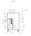
- the electronic components 130 are a switching element, a diode, a capacitor, and the like, and are directly attached to the base 150 of the heat sink 105 via the rectangular window 170 of the second parting plate 107A as in the above-described embodiment. As shown in FIGS. 6 and FIG. 8 , the electronic components 130 are arranged along an upper part of the second parting plate 107A. As shown in FIG. 9 , the electronic components 131 are a transformer, a reactor, and the like, and each includes a coil portion 131A and terminal portions 131B.
- each coil portion 131A is located in the first air path 109, and the terminal portions 131B are arranged in the layout space B101 in which the electronic components 130 are likewise arranged.
- the electronic components 131 extend through the lower part of the second parting plate 107A, and are arranged so as to face the layout space B101 and the first air path 109.
- the electronic components 131 used in such a power supply apparatus A101 are relatively large and heavy. Therefore, in order to weight-balance the electronic components 131 during fixing, the electronic components 131 are fixed so as to penetrate the second parting plate 107A, with the amount of the projection of the coil portions 131A facing the first air path 109 being adjusted. Note that the winding of the coil portions 131A of the electronic components 131 may be exposed, or may be sealed with molding resin.
- the heat sink 105 includes a base 150 fixed to the second parting plate 107A, and a plurality of vertically aligned fins 151 extending from the base 150 in the F direction.
- the electronic components 130 are directly attached via screws (not shown) or the like to one surface of the base 150 that faces the second parting plate 107A.
- the heat sink 105 is formed in a size that is larger than the rectangular window 170 of the second parting plate 107A and has a length in the F direction that is approximately the same as or shorter than the overall length of the air path 109'. In this embodiment as well, the heat sink 105 is cooled. Note that a plurality of heat sinks 105 may be arranged so as to be aligned in the F direction along the second parting plate 107A.
- the first parting plate 106 vertically separates spaces such as the layout space B102 for the fans 108 and 108' and the second air path 109' from the layout space B101 for the electronic components 130.
- the first parting plate 106 has approximately the same length in the F direction as that of the base member 101, and one of its ends in the transverse direction is bonded perpendicularly to the upper end of the second parting plate 107A. Consequently, the first parting plate 106 is horizontally located in a vertically intermediate portion of the casing cover 102.
- the first parting plate 106 forms the top wall of the layout space B102 for the fans 108 and 108' and the second air path 109'.
- the second parting plate 107A serves to separate the first and second air paths 109 and 109' from the layout space B101.
- the second parting plate 107A also has a dimension in the F direction that is approximately the same as that of the base member 101, and is arranged perpendicularly to the base member 101 and the first parting plate 106. In other words, the second parting plate 107A forms a vertical wall of the first and second air paths 109 and 109'.
- the upper part of the second parting plate 107A is provided with a rectangular window 170 for causing part of the base 150 of the heat sink 105 to be exposed to the layout space B101 and allowing the electronic components 130 to be attached to that part.
- the rectangular window 170 is closed by the base 150.
- An opening through which the electronic components 131 can be fitted is formed in a lower part of the second parting plate 107A (reference numeral is omitted).
- the second parting plate 107B serves to separate the second air path 109' from the layout space B102.
- the second parting plate 107B also has approximately the same dimension in the F direction as that of the base member 101.
- the second parting plate 107B is arranged so as to be opposed to an upper part of the second parting plate 107A, and its upper and lower ends are bonded perpendicularly to the first parting plate 106 and the third parting plate 107C.
- the second parting plate 107B forms a vertical wall of the second air path 109'.
- An opening 171' for allowing the second fan 108' to face the second air path 109' is provided in an intermediate portion in the F direction of the second parting plate 107B (see FIG. 10 ).
- the third parting plate 107C is formed in a shape having an L-shaped cross section so as to surround the first air path 109.
- the third parting plate 107C as well has approximately the same dimension in the F direction as that of the base member 101. Whereas the tip end of a horizontal part of the third parting plate 107C is bonded perpendicularly to the central part of the second parting plate 107A, the base end of the vertical part is bonded perpendicularly to the base member 101.
- the horizontal part of the third parting plate 107C forms the top wall of the first air path 109 and the bottom wall of the second air path 109', and the vertical part forms a vertical wall of the first air path 109 that is opposed to a lower part of the second parting plate 107A.
- An opening 171 for allowing the first fan 108 to face the first air path 109 is provided in an intermediate portion in the F direction of the vertical part of the third parting plate 107C (see FIG. 9 ).
- the first fan 108 includes a suction port 180 and a discharge port 181 for air.
- the first fan 108 is arranged such that the discharge port 181 coincides with the opening 171 of the third parting plate 107C.
- the first fan 108 is arranged in a longitudinally intermediate portion of the first air path 109, and the discharge port 181 is located so as to face the air path 109. Consequently, the blowing direction of the first fan 108 is a direction intersecting the longitudinal direction of the first air path 109 in the horizontal plane.
- the suction port 180 is located in the layout space B102, and is opposed to the side surface portion 102A with a predetermined interval.
- the intake port portion 120 is not provided in an area of the side surface portion 102A that is in front of the suction port 180. In other words, the suction port 180 is located a certain distance away from the intake port portions 120 located near two ends of the side surface portion 102A in the F direction.
- the second fan 108' includes a suction port 180' and a discharge port 181' for air.
- the second fan 108' is arranged such that the discharge port 181' coincides with the opening 171' of the second parting plate 107B.
- the second fan 108' is arranged in a longitudinally intermediate portion of the second air path 109', and the discharge port 181' is located so as to face the air path 109'. Consequently, the blowing direction of the second fan 108' is a direction intersecting the longitudinal direction of the second air path 109' in the horizontal plane.
- the suction port 180' is located in the layout space B102, and is opposed to the side surface portion 102A with a predetermined interval.
- the intake port portion 120 is also not provided in an area of the side surface portion 102A that is in front of the suction port 180'.
- the suction port 180' is located a certain distance away from the intake port portions 120 located near two ends of the side surface portion 102A in the F direction.
- the first air path 109 directly air-cools the electronic components 131 by air draft from the first fan 108, and guides the air draft to two ends in the longitudinal direction.
- the first air path 109 is surrounded by a lower part of the second parting plate 107A and the vertical part of the third parting plate 107C serving as a pair of vertical walls that are opposed to each other in the width direction, as well as by the horizontal part of the third parting plate 107C and part of the base member 101 serving as the top wall and the bottom wall that are vertically opposed to each other, and is formed in a shape having a rectangular cross section.
- the two ends of the air path 109 in the longitudinal direction each serve as an exit 190 from which air draft blows out.
- the air draft that has been blown from the first fan 108 into the first air path 109 directly strikes the coil portions 131A of the electronic components 131, and is split into two air streams flowing to the two ends of the first air path 109 in the longitudinal direction. Then, the air streams blow out from the exits 190, while drawing a large amount of heat away from the coil portions 131A.
- the distance for which the air draft flows from the first fan 108 to each of the exits 190 within the first air path 109 is shorter than the overall length of the first air path 109, and the air draft is quickly discharged to the outside. This allows the electronic components 131 to be efficiently air-cooled by air draft flowing through the first air path 109.
- the air draft blowing out from the exits 190 quickly blows to the outside through the ventilating hole portions 121 provided in the front surface portion 102C and the rear surface portion 102D of the casing cover 102.
- the second air path 109' air-cools the heat sink 105 using air draft from the second fan 108', and guides that air draft to its two ends in the longitudinal direction.
- the second air path 109' is surrounded by the upper part of the second parting plate 107A and the second parting plate 107B serving as a pair of vertical walls that are opposed to each other in the width direction, as well as by part of the first parting plate 106 and the horizontal part of the third parting plate 107C serving as the top wall and the bottom wall that are vertically opposed to each other, and is formed in a shape having a rectangular cross section.
- the two ends of the second air path 109' in the longitudinal direction each serve as an exit 190' from which air draft blows out.
- the air draft that has been blown from the second fan 108' into the second air path 109' directly strikes the heat sink 105, and is split into two air streams flowing to the two ends of the second air path 109' in the longitudinal direction. Then, the air streams blow out from the exits 190', while drawing a large amount of heat away from the heat sink 105.
- the distance for which the air draft flows from the second fan 108' to each of the exits 190' within the second air path 109' is also shorter than the overall length of the second air path 109', and the air draft is quickly discharged to the outside. This allows the electronic components 130 to be efficiently cooled via the heat sink 105.
- the air draft blowing out from the exits 190' quickly blows to the outside through the ventilating hole portions 121 provided in the front surface portion 102C and the rear surface portion 102D of the casing cover 102.
- the electronic components 130 and the electronic components 131 generate heat, resulting in an increase in the temperature of the power supply apparatus A101.
- the heat of each of the electronic components 130 is conducted into the air in the layout space B101, and is also directly conducted to the heat sink 105.
- the heat that has been conducted to the heat sink 105 is efficiently dissipated into the air in the second air path 109' by the plurality of fins 151.
- the coil portions 131A in the electronic components 131 have the greatest tendency to generate heat, and the heat of each of the coil portions 131A is conducted to the air in the first air path 109.
- the air present in the vicinity of the suction ports 180 and 180' is taken in by the first and second fans 108 and 108', and that air is blown as air draft from the discharge ports 181 and 181' into the air paths 109 and 109' in a direction intersecting the longitudinal direction of the first and second air paths 109 and 109'.
- outside air flows into the layout space B102 from the intake port portions 120.
- the air in the layout space B102 Upon activation of the first and second fans 108 and 108', the air in the layout space B102 is sucked into the suction ports 180 and 180'.
- the pressure in the layout space B102 becomes lower than that of the pressure outside the layout space B102.
- the air is sucked from the outside of the layout space B102 into the layout space B102 through the intake port portions 120 connecting the layout space B102 with the outside of the layout space B102. Since the power supply apparatus A101 is used in an environment with a lot of dust, the air outside the layout space B102 contains a lot of dust. Therefore, the air that is sucked into the layout space B102 also contains a lot of dust.
- the dust-containing air that has been sucked from the intake port portions 120 into the layout space B102 remains in the layout space B102 before flowing into the suction ports 180 and 180'.
- the air that is sucked into the suction ports 180 and 180' contains little dust.
- the first fan 108 can take in the air containing little dust and blow out that air into the first air path 109.
- the second fan 108' can take in the air containing little dust and blow out that air into the second air path 109'.
- the air draft that has been blown from the first fan 108 into the first air path 109 strikes the electronic components 131, while being split into two air streams and flowing to the two ends of the air path 109 in the longitudinal direction. At that time, air draft directly strikes the coil portions 131A of the electronic components 131, and therefore heat can be efficiently drawn away from the coil portions 131A. Further, the air draft that has exited from the first fan 108 is split into two air streams flowing to the two ends of the first air path 109 in the longitudinal direction. These air streams flow a relatively short distance until they are discharged to the outside from the two exits 190. Accordingly, the resistance of the air draft flowing through the first air path 109 is reduced, and the air draft is quickly discharged from the exits 190. This allows the electronic components 131 to be efficiently air-cooled.
- the air draft that has been blown from the second fan 108' into the second air path 109' directly strikes the heat sink 105 and flows along the fins 151 to the two ends of the air path 109' in the longitudinal direction. At that time, the air draft efficiently strikes many fins 151, and therefore a large amount of heat is drawn away from the surface of each of the fins 151. Further, the air draft that has exited from the second fan 108' is split into two air streams flowing to the two ends of the second air path 109' in the longitudinal direction. These air streams flow a relatively short distance until they are discharged to the outside from the two exits 190'.
- the resistance of the air draft flowing through the second air path 109' is reduced, and the air draft is quickly discharged from the exits 190'.
- This allows the heat sink 105 to be efficiently air-cooled, and also enables the electronic components 130 to be efficiently cooled via the heat sink 105.
- the electronic components 130 located in the upper section and the electronic components 131 located in the lower section are cooled by the air draft from the first and second fans 108 and 108', without being thermally influenced by each other. This allows the electronic components 130 and the electronic components 131 as well to be efficiently air-cooled.
- the first and second fans 108 and 108' may have different cooling powers.
- the first and second fans 108 and 108' may be activated with different timing in accordance with the difference.
- the distance between the first fan 108 and each of the electronic components 131 in the longitudinal direction of the first air path 109 and the distance between the second fan 108' and each of the electronic components 130 in the longitudinal direction of the second air path 109' are shorter than the overall length of the air paths 109 and 109', and therefore the electronic components 130 and the electronic components 131 are arranged in positions relatively close to their respective fans 108 and 108'. Accordingly, the electronic components 130 and the electronic components 131 can be arranged in the F direction along the first and second air paths 109 and 109' with a certain degree of flexibility.
- a dust removal operation using an air blow gun is performed.
- compressed air is jetted from, for example, one of the exits 190 of the first air path 109, with an air jet nozzle of the air blow gun being aimed at the interior of the air path 109.
- the compressed air forms a jet following the longitudinal direction of the first air path 109, and vigorously blows away, for example, the dust attached to the coil portions 131A of the electronic components 131 to the other exit 190.
- the jetting direction of the compressed air jetted from the air blow gun is a direction in conformity with the longitudinal direction of the first air path 109, or in other words, a direction intersecting the blowing direction of the first fan 108.
- the first fan 108 will not be rotated in reverse at high speed by a strong jet of compressed air during a dust removal operation using the air blow gun, and the blades and the rotational bearings of the fan 108 are thus in no danger of being damaged.
- a dust removal operation using an air blow gun can be performed for the second air path 109' as well. At that time, the blades and the rotational bearings of the second fan 108' are in no danger of being damaged.
- FIG. 11 shows another embodiment of a power supply apparatus.
- a power supply apparatus A102 shown in FIG. 11 is configured by adding electronic components 131 to the power supply apparatus A100 shown in FIGS. 1 to 3 and arranging the electronic components 131 in predetermined positions.
- the electronic components 131 are arranged in such a manner that they extend through the parting plate 106 serving as the top wall of the air path 109 and that the coil portions 131A are located in the air path 109.
- the air draft from the fan 108 flows to the two ends of the air path 109 in the longitudinal direction, while striking the coil portions 131A of the electronic components 131 and the fins 151 of the heat sink 105, and blows from the exits 190 to the outside.
- a plurality of electronic components arranged along different walls of a single air path 109 can be efficiently air-cooled.
- the same effect can also be achieved by arranging the electronic components on the vertical wall on which the fan is arranged, or on the bottom wall that is opposed to the top wall.
- FIG. 12 shows another embodiment of a power supply apparatus. Note that a power supply apparatus A202 shown in FIG. 12 is different from the power supply apparatus A102 in terms of the position of the intake port portions 220.
- the intake port portions 220 in a side surface portion 202A of a casing cover 202 are provided in areas that are near two ends of the side surface portion 202A in the F direction and are in the vicinity of a vertically intermediate portion of the side surface portion 202A.
- the intake port portions 220 are arranged in positions spaced above such a floor surface to some degree.
- the amount of dust sucked into the layout space B202 through the intake port portions 220 along with the air can be suppressed, which in turn suppresses the amount of dust entering the first and second air paths from the first and second fans 208 and 208' in a more effective manner.
- a plurality of fans may be arranged in a single air path.
- the electronic components to be cooled may be arranged along the bottom wall and the top wall of the air path, or along the vertical wall on which the fan is arranged.
- the electronic components may be arranged so as to directly face the air path.
- the fan may be arranged at one end of the air path in the longitudinal direction, and may be of the axial flow type where the fan is configured to blow air draft from that end in the longitudinal direction to the other end.
- a cover member including a fan-opposed wall may be separately provided on the suction port-side of the fan, and the layout space for the fan may be formed by surrounding the fan by this cover member.
- the intake port portions may be provided in the fan-opposed wall of such a cover member in an area displaced, in an in-plane direction of the fan-opposed wall, relative to an area in front of the suction port.
- FIGS. 13 to 21 show one embodiment of a power supply apparatus.
- a power supply apparatus A300 of this embodiment is used, for example, for outputting large current and high voltage required for arc welding.
- the power supply apparatus A300 is used, for example, in an environment with a lot of dust, such as a factory.
- the power supply apparatus A300 includes a base member 301, a casing cover 302, electronic components 330 and electronic components 331 constituting a power circuit, a heat sink 305, a first parting plate 306, second parting plates 307A and 307B, a third parting plate 307C, first and second fans 308 and 308', as well as first and second temperature sensors 300S and 300S' (see FIGS. 15 and 16 ).
- a hollow first air path 309 is provided that is surrounded by the lower part of the second parting plate 307A, the third parting plate 307C, and part of the base member 301.
- a hollow second air path 309' is provided that is surrounded by part of the first parting plate 306, an upper part of the second parting plate 307A, the second parting plate 307B, and part of the third parting plate 307C.
- the air paths 309 and 309' extend longitudinally in the front-rear direction of the power supply apparatus A300 (hereinafter, referred to as "F direction").
- a layout space B301 for the electronic components 330 and the like that is surrounded by part of the base member 301, part of the casing cover 302, part of the first parting plate 306, and the second parting plate 307A is provided in the apparatus outward of the first and second air paths 309 and 309'.
- a layout space B302 for the fans 308 and 308' is provided that is surrounded by part of the base member 301, part of the casing cover 302, part of the first parting plate 306, the second parting plate 307B, and the third parting plate 307C.
- the layout space B301 for the electronic components 330 and the like is in communication with a space located above the first parting plate 306.
- the base member 301 is an elongated rectangular plate member that is elongated in the F direction.
- a plurality of wheels 310 are pivotally attached to the under surface of the base member 301 via brackets. The wheels 310 allow the base member 301 to move on a floor surface.
- the second parting plate 307A is arranged in the central portion of the top surface of the base member 301, perpendicularly to the top surface.
- the third parting plate 307C is arranged so as to cover a lower part of one side of the second parting plate 307A and part of the top surface of the base member 301.
- the casing cover 302 is made of, for example, metal and serves to protect the interior of the apparatus.
- the casing cover 302 has the shape of a box that is removable from the base member 301, and includes two side surface portions 302A and 302B forming vertical planes along two lateral sides of the base member 301, and a front surface portion 302C and a rear surface portion 302D forming vertical planes along the front end and the rear end, respectively, of the base member 301.
- the side surface portion 302A of the casing cover 302 forms an opposed wall opposing to the first and second fans 308 and 308'.
- Intake port portions 320 for guiding outside air into the layout space B302 are provided in areas near two ends of the side surface portions 302A in the F direction (see FIGS. 15 and 16 ).
- the intake port portions 320 are each formed by many slit holes having a relatively small size.
- the areas of the front surface portion 302C and the rear surface portion 302D that correspond to the first and second air paths 309 and 309' are each provided with ventilating hole portions 321 for guiding air draft from the air paths 309 and 309' to the outside.
- the ventilating hole portions 321 are each formed by many holes having a relatively large size for better ventilation.
- the electronic components 330 are a switching element, a diode, a capacitor, a microcomputer, and the like.
- the electronic components 330 are directly attached to the heat sink 305 through the upper part of the second parting plate 307A. Accordingly, heat from each of the electronic components 330 is quickly conducted to the heat sink 305.
- the electronic components 331 are a transformer, a reactor, and the like, and each include a coil portion 331A and terminal portions 331B.
- each coil portion 331A is located in the first air path 309, and the terminal portions 331B are arranged in the layout space B301 in which the electronic components 330 are likewise arranged.
- the electronic components 331 extend through a lower part of the second parting plate 307A, and are arranged so as to face the layout space B301 and the first air path 309.
- Such electronic components 331 are relatively large and heavy. For this reason, the electronic components 331 are weight-balanced when being fixed so as to penetrate the second parting plate 307A, and the amount of projection of the coil portions 331A facing the first air path 309 is adjusted.
- the winding of the coil portions 331A of the electronic components 331 may be exposed, or the winding may be sealed by molding resin.
- the microcomputer may be incorporated in a control circuit different from the power circuit.
- the heat sink 305 is a heat dissipating member made of, for example, aluminum, and includes a base 350 fixed to the second parting plate 307A, and a plurality of vertically aligned fins 351 extending from the base 350 in the F direction.
- the electronic components 330 are directly attached via screws (not shown) or the like to part of the base 350 that is opposed to the second parting plate 307A.
- the plurality of fins 351 are portions that efficiently dissipate the heat conducted from the base 350 into the air, and have an increased surface area to achieve an improved heat dissipating effect.
- the heat sink 305 is also cooled. Note that a plurality of heat sinks 305 may be arranged so as to be aligned in the F direction along the second parting plate 307A.
- the first parting plate 306 is made of, for example, metal and serves to vertically separate spaces such as the layout space B302 for the fans 308 and 308' and the second air path 309' from the layout space B101 for the electronic components 330.
- the first parting plate 306 has approximately the same length in the F direction as that of the base member 301, and one of its ends in the transverse direction is bonded perpendicularly to the upper end of the second parting plate 307A. Consequently, the first partingplate 306 is horizontally located in a vertically intermediate portion of the casing cover 302.
- the first parting plate 306 forms the top wall of the layout space B302 for the fans 308 and 308' and the second air path 309'.
- the second parting plate 30 7A is made of, for example, metal and serves to separate the first and second air paths 309 and 309' from the layout space B301.
- the second parting plate 307A also has a dimension in the F direction that is approximately the same as that of the base member 301.
- the second parting plate 307A is arranged perpendicularly to the base member 301 and the first parting plate 306. Accordingly, the second parting plate 307A forms a vertical wall of the first and second air paths 309 and 309'.
- the upper part of the second parting plate 307A is provided with a rectangular window 370 for causing part of the base 350 of the heat sink 305 to be exposed to the layout space B301 and allowing the electronic components 330 to be attached to that part.
- the rectangular window 370 is formed in a size slightly smaller than that of the base 350, and is closed by the base 350.
- An opening through which the electronic components 331 can be fitted is formed in a lower part of the second parting plate 307A (reference numeral is omitted).
- the second parting plate 307B is made of, for example, metal and serves to separate the second air path 309' from the layout space B302.
- the second parting plate 307B also has approximately the same dimension in the F direction as that of the base member 301.
- the second parting plate 307B is arranged so as to be opposed to an upper part of the second parting plate 307A, and its upper and lower ends are bonded perpendicularly to the first parting plate 306 and the third parting plate 307C. Accordingly, the second parting plate 307B forms a vertical wall of the second air path 309'.
- An opening 371' for allowing the second fan 308' to face the second air path 309' is provided in an intermediate portion in the F direction of the second parting plate 307B (see FIG. 16 ).
- the third parting plate 307C is made of, for example, metal and is formed in a shape having an L-shaped cross section so as to surround the first air path 309.
- the third parting plate 307C as well has approximately the same dimension in the F direction as that of the base member 301. Whereas the tip end of a horizontal part of the third parting plate 307C is bonded perpendicularly to the central part of the second parting plate 307A, the base end of the vertical part is bonded perpendicularly to the base member 301.
- the horizontal part of the third parting plate 307C forms the top wall of the first air path 309 and the bottom wall of the second air path 309', and the vertical part forms a vertical wall of the first air path 309 that is opposed to a lower part of the second parting plate 307A.
- An opening 371 for allowing the first fan 308 to face the first air path 309 is provided in an intermediate portion in the F direction of the vertical part of the third parting plate 307C (see FIG. 15 ).
- the lower first fan 308 is of the axial flow type where a plurality of blades and an electric motor (not shown) are integrated, and includes a suction port 380 and a discharge port 381 for air on two axial ends of its electric motor.
- the first fan 308 is arranged such that the discharge port 381 coincides with the opening 371 of the third parting plate 307C.
- the first fan 308 is arranged in a longitudinally intermediate portion of the first air path 309, and the discharge port 381 is located so as to face the air path 309. Consequently, the blowing direction of the first fan 308 is a direction intersecting the longitudinal direction of the first air path 309 in the horizontal plane.
- the suction port 380 is located in the layout space B302, and is opposed to the side surface portion 302A with a predetermined interval.
- the intake port portion 320 is not provided in an area of the side surface portion 302A that is in front of the suction port 380.
- the suction port 380 is located a certain distance away from the intake port portions 320 located near two ends of the side surface portion 302A in the F direction.
- the upper second fan 308' is of the axial flow type as with the first fan 308, and includes a suction port 380' and a discharge port 381' for air on the two axial ends.
- the second fan 308' is arranged such that the discharge port 381' coincides with the opening 371' of the second parting plate 307B.
- the second fan 308' is arranged in a longitudinally intermediate portion of the second air path 309', and the discharge port 381' is located so as to face the air path 309'. Consequently, the blowing direction of the second fan 308' is a direction intersecting the longitudinal direction of the second air path 309' in the horizontal plane.
- the suction port 380' is located in the layout space B302, and is opposed to the side surface portion 302A with a predetermined interval.
- the intake port portion 320 is not provided in an area of the side surface portion 302A that is in front of the suction port 380'.
- the suction port 380' is located a certain distance away from the intake port portions 320 located near two ends of the side surface portion 302A in the F direction.
- the first and second fans 308 and 308' have air volumes different from each other, and the upper second fan 308' has a larger air volume than that of the lower first fan 308.
- the first air path 309 directly air-cools the electronic components 331 using air draft from the first fan 308, and guides that air draft to its two ends in the longitudinal direction.
- the first air path 309 is surrounded by a lower part of the second parting plate 307A and the vertical part of the third parting plate 307C serving as a pair of vertical walls that are opposed to each other in the width direction, as well as by the horizontal part of the third parting plate 307C and part of the base member 301 serving as the top wall and the bottom wall that are vertically opposed to each other, and is formed in a shape having a rectangular cross section.
- the two ends of the first air path 309 in the longitudinal direction each serve as an exit 390 from which air draft blows out.
- the air draft that has been blown from the first fan 308 into the first air path 309 directly strikes the coil portions 331A of the electronic components 331, and is split into two air streams flowing to the two ends of the first air path 309 in the longitudinal direction. Then, the air streams blow out from the exits 39090, while drawing a large amount of heat away from the coil portions 331A.
- the air draft quickly blows to the outside through the ventilating hole portions 321 provided in the front surface portion 302C and the rear surface portion 302D of the casing cover 302.
- the average distance for which the air draft flows from the first fan 308 to each of the exits 390 within the first air path 309 is about half the overall length of the air path 309. This enables the air draft from the first fan 308 to quickly flow through the first air path 309 and to be discharged to the outside, allowing the electronic components 331 to be efficiently air-cooled by air draft flowing through the first air path 309.
- the first air path 309 is provided with the first temperature sensor 300S for detecting the internal temperature thereof.
- the first temperature sensor 300S is arranged, for example, on the surface of the second parting plate 307A. Note that the first temperature sensor 300S may be directly attached, for example, to the electronic components 331.
- the first temperature sensor 300S outputs a signal to the microcomputer.
- the microcomputer prevents the first fan 308 from operating when the internal temperature of the first airpath 309 is less than 50°C, for example.
- the microcomputer causes the first fan 308 to be rotated at low speed when the internal temperature of the first air path 309 is 50°C or greater and less than 70°C.
- the microcomputer causes the first fan 308 to be rotated at high speed when the internal temperature of the first air path 309 has increased to 70°C or greater.
- the microcomputer stops the overall operation of the power circuit constituted by the electronic components 330 and the electronic components 331 when the internal temperature of the first air path 309 has increased from 70°C and reached a predetermined temperature.
- the second air path 309' air-cools the heat sink 305 using air draft from the second fan 308', and guides that air draft to its two ends in the longitudinal direction.
- the second air path 309' is surrounded by the upper part of the second parting plate 3 0 7A and the second parting plate 307B serving as a pair of vertical walls that are opposed to each other in the width direction, as well as by part of the first parting plate 306 and the horizontal part of the third parting plat 307C serving as the top wall and the bottom wall that are vertically opposed to each other, and is formed in a shape having a rectangular cross section.
- the second air path 309' is separated from the first air path 309 by the horizontal part of the third parting plate 307C as the partition wall, and is arranged above the first air path 309.
- the two ends of the second air path 309' in the longitudinal direction each serve as an exit 390' from which air draft blows out.
- the air draft that has been blown from the second fan 308' into the second air path 309' directly strikes the heat sink 305, and is split into two air streams flowing to the two ends of the second air path 309' in the longitudinal direction. Then, the air streams blow out from the exits 390', while drawing a large amount of heat away from the heat sink 305.
- the average distance for which the air draft flows from the second fan 308' to each of the exits 390' within the second air path 309' as well is about half the overall length of the air path 309'. This enables the air draft from the second fan 308' to quickly flow through the second air path 309' and to be discharged to the outside, allowing the heat sink 305 to be efficiently air-cooled by air draft flowing through the second air path 309'. Consequently, the electronic components 330 are efficiently cooled via the heat sink 305.
- the second air path 309' is provided with the second temperature sensor 300S' for detecting the internal temperature thereof.
- the second temperature sensor 300S' is arranged, for example, on the surface of the second parting plate 307A. Note that the second temperature sensor 300S' may be directly attached, for example, to the heat sink 305.
- the second temperature sensor 300S' outputs a signal to the microcomputer.
- the microcomputer prevents the second fan 308' from operating when the internal temperature of the second air path 309' is less than 40°C, for example.
- the microcomputer causes the second fan 308' to be rotated at low speed when the internal temperature of the second air path 309' is 40°C or greater and less than 60°C.
- the microcomputer causes the second fan 308' to be rotated at high speed when the internal temperature of the second air path 309' has increased to 60°C or greater. Further, the microcomputer stops the overall operation of the power circuit constituted by the electronic components 330 and the electronic components 331 when the internal temperature of the second air path 309' has increased from 60°C and reached a predetermined temperature.
- the electronic components 330 and the electronic components 331 generate heat as the power supply apparatus A300 outputs large current and high voltage for welding, resulting in an increase in the temperature of the power supply apparatus A300.
- the heat of each of the electronic components 330 is conducted into the air in the layout space B301, and is also directly conducted to the heat sink 305.
- the heat that has been conducted to the heat sink 305 is efficiently dissipated into the air in the second air path 309' by the plurality of fins 351.
- the coil portions 331A in the electronic components 331 have the greatest tendency to generate heat, and the heat of each of the coil portions 331A is conducted to the air in the first air path 309'.
- the air present in the vicinity of the suction ports 380 and 380' is sucked in by the first and second fans 308 and 308', and that air is blown as air draft from the discharge port 381 into the air paths 309 and 309' in a direction intersecting the longitudinal direction of the first and second air paths 309 and 309'.
- outside air flows into the layout space B302 from the intake port portions 320.
- the air in the layout space B302 Upon activation of the first and second fans 308 and 308', the air in the layout space B302 is sucked into the suction ports 380 and 380'.
- the pressure in the layout space B302 becomes lower than that of the pressure outside the layout space B302. Then, the air is sucked from the outside of the layout space B302 into the layout space B302 through the intake port portions 320 connecting the layout space B302 with the outside of the layout space B302. Since the power supply apparatus A300 is used in an environment with a lot of dust, the air outside the layout space B302 contains a lot of dust. Therefore, the air that is sucked into the layout space B302 also contains a lot of dust.
- the dust-containing air that has been sucked from the intake port portions 320 into the layout space B302 remains in the layout space B302 before flowing into the suction ports 380 and 380'.
- the air that is sucked into the suction ports 380 and 380' contains little dust.
- the first fan 308 can take in the air containing little dust and blow out that air into the first air path 309.
- the second fan 308' can take in the air containing little dust and blow out that air into the second air path 309'
- the air draft that has been blown from the first fan 308 into the first air path 309 strikes the electronic components 331, while being split into two air streams and flowing to the two ends of the air path 309 in the longitudinal direction. At that time, air draft directly strikes the coil portions 331A of the electronic components 331, and therefore heat can be efficiently drawn away from the coil portions 331A. Further, the air draft that has exited from the first fan 308 is split into two air streams flowing to the two ends of the first air path 309 in the longitudinal direction. These air streams flow a relatively short distance until they are discharged to the outside from the two exits 390. Accordingly, the resistance of the air draft flowing through the first air path 309 is reduced, and the air draft is quickly discharged from the exits 390. This allows the electronic components 331 to be efficiently air-cooled.
- the air draft that has been blown from the second fan 308' into the second air path 309' directly strikes the heat sink 305 and flows along the fins 351 to the two ends of the second air path 309' in the longitudinal direction. At that time, the air draft efficiently strikes many fins 351, and therefore a large amount of heat is drawn away from the surface of each of the fins 351. Further, the air draft that has exited from the second fan 308' is split into two air streams flowing to the two ends of the air path 309' in the longitudinal direction. These air streams flow a relatively short distance until they are discharged to the outside from the two exits 390'.
- the resistance of the air draft flowing through the second air path 309' is reduced, and the air draft is quickly discharged from the exits 390'.
- This allows the heat sink 305 to be efficiently air-cooled, and also enables the electronic components 330 to be efficiently cooled via the heat sink 305.
- the first and second air paths 309 and 309' are separated into an upper section and a lower section by the horizontal part of the third parting plate 307C. Therefore, for example, the air in the first air path 309 in the lower section that has been heated by the heat from the electronic components 331 tends to rise as its temperature increases, but is quickly discharged to the outside without entering the second air path 309' in the upper section. Accordingly, the electronic components 330 located in the upper section and the electronic components 331 located in the lower section are efficiently cooled by the air draft from the first and second fans 308 and 308', without being thermally influenced by each other.
- the first and second fans 308 and 308' have different air volumes. Furthermore, the rotational speeds of the first and second fans 308 and 308' are variably controlled according to the internal temperatures of the first and second air paths 309 and 309'. Accordingly, the air draft flowing through the first the and second air paths 309 and 309' are set to suitable air speeds according to the objects that are to be cooled and the temperature rising characteristics, and the heat sink 305 located in the upper section and the electronic components 331 located in the lower section are efficiently cooled by air drafts of different air speeds. In this embodiment, in particular, the air volume of the upper second fan 308' is larger than that of the lower first fan 308.
- the heat sink 305 located in the upper section can be more easily air-cooled, and the electronic components 330 are efficiently cooled via such a heat sink 305. Furthermore, the first and second fans 308 and 308' are controlled independently of each other, and the operation of these fans is stopped until the internal temperatures of the first and second air paths 309 and 309' reach predetermined temperatures, which also contributes to power saving and noise reduction.
- the power supply apparatus A300 is placed, for example, on a floor surface in a factory. In the vicinity of the floor surface, dust tends to accumulate and air containing an increased amount of dust is present.
- the first and second fans 308 and 308' are activated in such a state, the lower first fan 308 tends to suck the air present close to the floor surface more than the upper fan does.
- the lower first fan 308 has a smaller air volume and a lower suction power than the upper second fan 308'. This suppresses the amount of dust sucked in by the lower first fan 308, making it possible to prevent the entry of dust from the first fan 308 in an effective manner even for the lower air path 309, which is located closer to the floor surface.
- the internal temperatures of the first and second air paths 309 and 309' rise.
- the internal temperatures of the first and second air paths 309 and 309' are independently detected by the first and second temperature sensors 300S and 300S', and the overall operation of the power circuit constituted by the electronic components 330 and the electronic components 331 is stopped when the internal temperature of either one of the first and second air paths 309 and 309' reaches a temperature greater than equal to a predetermined temperature.
- the power supply apparatus A300 has a fail-safe function by which, for example, the overall operation can be immediately stopped by merely a sudden reduction in the cooling power of either one of the first and second air paths 309 and 309', and therefore can safely output large current and high voltage necessary for arc welding or the like.
- a fan having a high air volume may be used as the first fan 308 in the lower section.
- the first and second fans 308 and 308' may be activated with different timing in accordance with the difference.
- the first and second fans 308 and 308' are located in longitudinally intermediate portions of the first and second air paths 309 and 309', as a result of which the electronic components 330 and the electronic components 331 that are to be cooled are located in the vicinity of their respective fans 308 and 308'.
- the distance between the first fan 308 and each of the electronic components 331 in the F direction and the distance between the second fan 308' and each of the electronic components 330 in the F direction are shorter than the overall lengths of the first and second air paths 309 and 309', and therefore the electronic components 330 and the electronic components 331 are arranged in positions relatively close to the fans 308 and 308'.
- This positional relationship in the F direction also allows the electronic components 330 and the electronic components 331 to be efficiently cooled. Accordingly, it is not necessary to determine the positions of the electronic components 330 and the electronic components 331 in the F direction according to their heat-generating properties, and it is therefore possible to arrange these electronic components with a certain degree of flexibility.
- a dust removal operation using an air blow gun is performed.
- compressed air is jetted from, for example, one of the exits 390 of the first air path 309, with an air jet nozzle of the air blow gun being aimed at the interior of the air path 309.
- the compressed air forms a jet following the longitudinal direction of the first air path 309, and vigorously blows away, for example, the dust attached to the coil portions 331A of the electronic components 331 to the other exit 390.
- the jetting direction of the compressed air jetted from the air blow gun is a direction in conformity with the longitudinal direction of the first air path 309, or in other words, a direction intersecting the blowing direction of the first fan 308.
- the first fan 308 will not be rotated in reverse at high speed by a strong jet of compressed air during a dust removal operation using the air blow gun, and the blades and the rotational bearings of the fan 308 are thus in no danger of being damaged.
- a dust removal operation using an air blow gun can be performed for the second air path 309' as well.
- the blades and the rotational bearings of the second fan 308' are in no danger of being damaged.
- FIGS. 22 and 23 show other embodiments of a power supply apparatus.
- a power supply apparatus A301 shown in FIG. 22 is configured by adding electronic components 332 that are different from those of the above-described embodiments and arranging the electronic components 332 in predetermined positions.
- a power supply apparatus A302 shown in FIG. 23 is different from the above-described embodiments in the position of intake port portions 320. Components that are identical or similar to those of the above-described embodiments are denoted by identical or similar reference numerals, and the description thereof has been omitted.
- the electronic components 332 are arranged in such a manner that they extend through the first parting plate 306 serving as the top wall of the second air path 309' and that coil portions 332A are located in the air path 309'.
- the air draft from the second fan 308' flows to the two ends of the second air path 309' in the longitudinal direction, while striking the coil portions 332A of the electronic components 332 and the fins 351 of the heat sink 305, and blows to the outside.
- a plurality of electronic components arranged along different walls of a single air path 309' can be efficiently air-cooled.
- the same effect can also be achieved by arranging the electronic components on the vertical wall on which the fan is arranged, or on the bottom wall that is opposed to the top wall.
- the intake port portions 320 in the side surface portion 302A of the casing cover 302 are provided in areas that are near two ends of the side surface portion 302A in the F direction and are in the vicinity of a vertically intermediate portion of the side surface portion 302A.
- the intake port portions 320 are spaced above an area in the vicinity of the floor surface where dust accumulates.
- the amount of dust sucked into the layout space B302 through the intake port portions 320 along with the air can be suppressed, which in turn suppresses the amount of dust entering the first and second air paths from the first and second fans 308 and 308' in amore effective manner.
- the electronic components may be arranged so as to directly face the air path.
- the fan may be arranged at one end of the air path in the direction, and may be configured to blow air draft from that end in the longitudinal direction to the other end.
- the other end of the air path in the longitudinal direction serves as an exit for air draft.
- first and second air paths may be arranged so as to be adjacent to each other in the horizontal direction.
- the number of the air paths is not limited to two, and three or more air paths may be provided. In that case, fans are provided to respectively correspond to air paths.
Landscapes
- Engineering & Computer Science (AREA)
- Physics & Mathematics (AREA)
- Plasma & Fusion (AREA)
- Mechanical Engineering (AREA)
- Cooling Or The Like Of Electrical Apparatus (AREA)
Applications Claiming Priority (3)
| Application Number | Priority Date | Filing Date | Title |
|---|---|---|---|
| JP2010053085A JP2011188671A (ja) | 2010-03-10 | 2010-03-10 | 電源装置 |
| JP2010056937A JP5764295B2 (ja) | 2010-03-15 | 2010-03-15 | 電源装置 |
| JP2010074438A JP5596389B2 (ja) | 2010-03-29 | 2010-03-29 | 電源装置 |
Publications (2)
| Publication Number | Publication Date |
|---|---|
| EP2364807A1 true EP2364807A1 (fr) | 2011-09-14 |
| EP2364807B1 EP2364807B1 (fr) | 2013-05-08 |
Family
ID=44259925
Family Applications (1)
| Application Number | Title | Priority Date | Filing Date |
|---|---|---|---|
| EP11157498.4A Active EP2364807B1 (fr) | 2010-03-10 | 2011-03-09 | Appareil d'alimentation électrique incluant un ventilateur pour le refroidissement de l'air |
Country Status (3)
| Country | Link |
|---|---|
| US (1) | US8462505B2 (fr) |
| EP (1) | EP2364807B1 (fr) |
| CN (1) | CN102195455B (fr) |
Cited By (4)
| Publication number | Priority date | Publication date | Assignee | Title |
|---|---|---|---|---|
| WO2013068815A1 (fr) * | 2011-11-08 | 2013-05-16 | Lincoln Global, Inc. | Système et procédé pour le réglage en temps réel et la commande d'un ventilateur de refroidissement dans un système de soudage ou de coupe |
| CN106304794A (zh) * | 2016-09-28 | 2017-01-04 | 吴秦 | 一种大数据一体机的散热外壳 |
| WO2019168851A1 (fr) * | 2018-02-28 | 2019-09-06 | Illinois Tool Works Inc. | Souffleries à double chambre pour une source d'énergie de type soudage |
| CN114905200A (zh) * | 2022-07-18 | 2022-08-16 | 溧阳市飞跃机电有限公司 | 便于散热及自动化焊接风力发电机机壳的焊接装置 |
Families Citing this family (37)
| Publication number | Priority date | Publication date | Assignee | Title |
|---|---|---|---|---|
| US20110108250A1 (en) * | 2009-11-09 | 2011-05-12 | Alex Horng | Heat Dissipating device |
| US8331091B2 (en) * | 2010-09-01 | 2012-12-11 | Hamilton Sundstrand Corporation | Electronics package with radial heat sink and integrated blower |
| CN103492973A (zh) * | 2011-06-27 | 2014-01-01 | 惠普发展公司,有限责任合伙企业 | 通过使用与冷却主部件的热耗散设备相关联的空气通道使气流转向来冷却辅助部件 |
| JP5827513B2 (ja) * | 2011-07-25 | 2015-12-02 | 株式会社アイ・ライティング・システム | スイッチング電源装置 |
| TWM456072U (zh) * | 2012-11-16 | 2013-06-21 | Wistron Corp | 電子裝置及其機殼 |
| CN103019195A (zh) * | 2012-11-30 | 2013-04-03 | 福建星网锐捷网络有限公司 | 散热控制系统、方法和装置 |
| KR101278633B1 (ko) * | 2013-02-25 | 2013-06-25 | 김종선 | 서버 방열시스템 |
| US11027354B2 (en) * | 2013-06-24 | 2021-06-08 | Illinois Tool Works Inc. | Modular power conversion system and method |
| WO2015015659A1 (fr) | 2013-08-02 | 2015-02-05 | 株式会社小松製作所 | Dispositif de recharge |
| JP6219174B2 (ja) * | 2014-01-09 | 2017-10-25 | 株式会社三社電機製作所 | 電気機器 |
| DE102014207867A1 (de) * | 2014-04-25 | 2015-10-29 | Robert Bosch Gmbh | Werkzeugmaschinenkühlungsvorrichtung |
| JP2016032367A (ja) * | 2014-07-29 | 2016-03-07 | 株式会社安川電機 | 電力変換装置 |
| CN104181949A (zh) * | 2014-09-02 | 2014-12-03 | 航天长峰朝阳电源有限公司 | 电源智能冷却装置 |
| US10150173B2 (en) | 2014-11-07 | 2018-12-11 | Illinois Tool Works Inc. | Welding type power supply with wind tunnel |
| JP6166743B2 (ja) | 2015-02-20 | 2017-07-19 | 本田技研工業株式会社 | 電力変換装置 |
| KR101637827B1 (ko) * | 2015-04-13 | 2016-07-07 | 엘지전자 주식회사 | 진공 청소기 |
| CN106155192A (zh) * | 2015-04-14 | 2016-11-23 | 鸿富锦精密工业(武汉)有限公司 | 计算机 |
| JP6011735B1 (ja) * | 2016-01-29 | 2016-10-19 | 富士電機株式会社 | 電力変換装置 |
| US10143116B2 (en) * | 2016-05-13 | 2018-11-27 | Toshiba International Corporation | Outdoor UPS unit system and method |
| US11076501B2 (en) | 2017-05-23 | 2021-07-27 | Crestron Electronics, Inc. | Apparatus for cooling electronic circuitry |
| US11711904B2 (en) * | 2016-06-03 | 2023-07-25 | Crestron Electronics, Inc. | Apparatus for cooling electronic circuitry |
| US20170354060A1 (en) * | 2016-06-03 | 2017-12-07 | Crestron Electronics, Inc. | Apparatus for cooling electronic circuitry |
| US10238004B2 (en) * | 2016-11-07 | 2019-03-19 | Rockwell Automation Technologies, Inc. | Controller with enhanced thermal properties |
| WO2018134869A1 (fr) * | 2017-01-17 | 2018-07-26 | 三菱電機株式会社 | Dispositif de commande de véhicule |
| US11554450B2 (en) | 2017-05-25 | 2023-01-17 | Illinois Tool Works Inc. | Multiple speed fan |
| US11084115B2 (en) * | 2017-08-31 | 2021-08-10 | Illinois Tool Works Inc. | Cooling for inverter-based engine-driven welding-type power supply |
| CN107612289A (zh) * | 2017-09-21 | 2018-01-19 | 重庆集元科技有限公司 | 具有高安全性能的大功率电源 |
| CN108054935A (zh) * | 2017-12-25 | 2018-05-18 | 苍南县新源电子科技有限公司 | 易散热逆变器安装壳 |
| DE112019000365T5 (de) * | 2018-03-29 | 2020-10-01 | Koki Holdings Co., Ltd. | Gleichstromquelleneinheit |
| US10709036B2 (en) * | 2018-09-11 | 2020-07-07 | Quanta Computer Inc. | Removable PSU dedicated tunnel for air flow mechanism |
| US10897807B2 (en) | 2018-09-21 | 2021-01-19 | The Esab Group Inc. | Power source cooling apparatus, method, and configuration |
| USD914071S1 (en) | 2018-11-02 | 2021-03-23 | Esab Ab | Welding device enclosure |
| CN112821779A (zh) * | 2019-03-06 | 2021-05-18 | 泉州台商投资区春凯机械科技有限公司 | 一种太阳能光伏并网逆变器及其使用方法 |
| CN113286484B (zh) * | 2020-01-31 | 2023-07-21 | 日本电产三协株式会社 | 驱动装置 |
| US20220234742A1 (en) * | 2021-01-27 | 2022-07-28 | Antonio Alvarez | Aircraft Sanitizer |
| TWI778522B (zh) * | 2021-02-19 | 2022-09-21 | 德承股份有限公司 | 防塵式散熱機構及具有防塵式散熱機構的電子裝置 |
| US20230007809A1 (en) * | 2021-07-02 | 2023-01-05 | Rohde & Schwarz Gmbh & Co. Kg | Heat management arrangement, method of manufacturing and electronic device |
Citations (7)
| Publication number | Priority date | Publication date | Assignee | Title |
|---|---|---|---|---|
| EP0900621A2 (fr) * | 1997-09-08 | 1999-03-10 | Lorch Schweisstechnik GmbH | Module d'alimentation électrique |
| EP1022085A2 (fr) * | 1998-12-22 | 2000-07-26 | The Esab Group, Inc. | Dispositif d'alimentation de puissance avec flux d'air oblique |
| US20020006027A1 (en) * | 2000-06-06 | 2002-01-17 | Rodriguez Edward T. | Thermal distribution system |
| WO2007043195A1 (fr) * | 2005-10-11 | 2007-04-19 | Matsushita Electric Industrial Co., Ltd. | Dispositif de soudage |
| US20080061048A1 (en) * | 2006-09-13 | 2008-03-13 | Hypertherm, Inc. | Power Supply Cooling Apparatus and Configuration |
| JP2008229644A (ja) | 2007-03-19 | 2008-10-02 | Matsushita Electric Ind Co Ltd | 電気機器 |
| JP2009248116A (ja) | 2008-04-04 | 2009-10-29 | Panasonic Corp | 溶接電源装置 |
Family Cites Families (32)
| Publication number | Priority date | Publication date | Assignee | Title |
|---|---|---|---|---|
| JP2658120B2 (ja) * | 1988-02-02 | 1997-09-30 | 日本電気株式会社 | 電子装置の冷却構造 |
| US5121291A (en) * | 1991-02-13 | 1992-06-09 | Mentor Systems, Inc. | Ventilation system in a portable computer |
| US5438226A (en) * | 1992-09-16 | 1995-08-01 | International Business Machines Corporation | Apparatus for redundant cooling of electronic devices |
| GB2295494B (en) * | 1994-11-25 | 1996-10-23 | Ming Der Chiou | Power supplier of direct current |
| US5624589A (en) * | 1995-09-11 | 1997-04-29 | Illinois Tool Works Inc. | Segregated cooling air flow for engine driven welder |
| US5642260A (en) * | 1996-01-16 | 1997-06-24 | Illinois Tool Works Inc. | Welding power supply housing |
| US6046921A (en) * | 1996-08-27 | 2000-04-04 | Tracewell; Larry L. | Modular power supply |
| US5963887A (en) * | 1996-11-12 | 1999-10-05 | The United States Of America As Represented By The Secretary Of The Navy | Apparatus for optimizing the rotational speed of cooling fans |
| US5831847A (en) * | 1997-02-05 | 1998-11-03 | Jerome Industries Corp. | Power supply with separated airflows |
| US5977644A (en) * | 1997-08-26 | 1999-11-02 | Lucent Technologies Inc. | Backup power system having improved cooling airflow and method of operation thereof |
| DE19930166A1 (de) * | 1999-06-30 | 2001-01-18 | Fujitsu Siemens Computers Gmbh | Kühleinrichtung und Temperaturkontrolleinheit für eine solche Kühleinrichtung für ein elektrisches Gerät |
| US6198642B1 (en) * | 1999-10-19 | 2001-03-06 | Tracewell Power, Inc. | Compact multiple output power supply |
| US6489591B1 (en) * | 2000-04-10 | 2002-12-03 | Illinois Tool Works Inc. | Cooling air circuits for welding machine |
| US6520851B1 (en) * | 2002-01-09 | 2003-02-18 | Shoei-Yuan Shih | Air fan configuration structure for power supply device |
| TW551545U (en) * | 2002-08-07 | 2003-09-01 | Tzung-Yan Tsai | Structure of power supply |
| US6621700B1 (en) * | 2002-09-26 | 2003-09-16 | Chromalox, Inc. | Heat sink for a silicon controlled rectifier power controller |
| US6888099B1 (en) * | 2003-03-06 | 2005-05-03 | Illinois Tool Works Inc. | Wind tunnel for a welding power supply housing |
| US6831838B1 (en) * | 2003-05-14 | 2004-12-14 | Illinois Tool Works Inc. | Circuit board assembly for welding power supply |
| US20050030711A1 (en) * | 2003-08-06 | 2005-02-10 | Tsung-Yen Tsai | Heat dissipating device of power supply |
| CN100586263C (zh) * | 2003-11-14 | 2010-01-27 | Det国际控股有限公司 | 改进冷却的电源 |
| JP4265443B2 (ja) * | 2004-02-27 | 2009-05-20 | ヤマハ株式会社 | 電気機器の空調構造 |
| JP4155234B2 (ja) * | 2004-06-24 | 2008-09-24 | 松下電器産業株式会社 | アーク溶接制御装置 |
| CN100502142C (zh) * | 2004-08-25 | 2009-06-17 | 丰田自动车株式会社 | 电源设备 |
| US20060185832A1 (en) * | 2005-02-23 | 2006-08-24 | Asia Vital Component Co., Ltd. | Heat radiation module with transverse flow fan |
| TWI262047B (en) * | 2005-03-03 | 2006-09-11 | Delta Electronics Inc | Electronic apparatus with waterproof and heat-dissipating structure |
| US7456373B2 (en) * | 2005-06-06 | 2008-11-25 | Illinois Tool Works Inc. | Welder with front mount fan |
| US7573713B2 (en) * | 2005-09-13 | 2009-08-11 | Pacific Star Communications | High velocity air cooling for electronic equipment |
| JP4655987B2 (ja) * | 2006-04-19 | 2011-03-23 | 株式会社豊田自動織機 | 電子機器 |
| JP4808178B2 (ja) * | 2007-04-17 | 2011-11-02 | 富士通株式会社 | 電子機器収納箱 |
| US7515412B2 (en) * | 2007-04-26 | 2009-04-07 | Enermax Technology Corporation | Cooling structure for power supply |
| CN101673088B (zh) * | 2008-09-12 | 2012-10-10 | 鸿富锦精密工业(深圳)有限公司 | 具有风扇冗余控制功能的电子设备 |
| JP5418847B2 (ja) * | 2009-08-04 | 2014-02-19 | 株式会社安川電機 | 電力変換装置 |
-
2011
- 2011-03-09 EP EP11157498.4A patent/EP2364807B1/fr active Active
- 2011-03-09 US US13/044,267 patent/US8462505B2/en active Active
- 2011-03-10 CN CN201110060011.5A patent/CN102195455B/zh active Active
Patent Citations (7)
| Publication number | Priority date | Publication date | Assignee | Title |
|---|---|---|---|---|
| EP0900621A2 (fr) * | 1997-09-08 | 1999-03-10 | Lorch Schweisstechnik GmbH | Module d'alimentation électrique |
| EP1022085A2 (fr) * | 1998-12-22 | 2000-07-26 | The Esab Group, Inc. | Dispositif d'alimentation de puissance avec flux d'air oblique |
| US20020006027A1 (en) * | 2000-06-06 | 2002-01-17 | Rodriguez Edward T. | Thermal distribution system |
| WO2007043195A1 (fr) * | 2005-10-11 | 2007-04-19 | Matsushita Electric Industrial Co., Ltd. | Dispositif de soudage |
| US20080061048A1 (en) * | 2006-09-13 | 2008-03-13 | Hypertherm, Inc. | Power Supply Cooling Apparatus and Configuration |
| JP2008229644A (ja) | 2007-03-19 | 2008-10-02 | Matsushita Electric Ind Co Ltd | 電気機器 |
| JP2009248116A (ja) | 2008-04-04 | 2009-10-29 | Panasonic Corp | 溶接電源装置 |
Cited By (8)
| Publication number | Priority date | Publication date | Assignee | Title |
|---|---|---|---|---|
| WO2013068815A1 (fr) * | 2011-11-08 | 2013-05-16 | Lincoln Global, Inc. | Système et procédé pour le réglage en temps réel et la commande d'un ventilateur de refroidissement dans un système de soudage ou de coupe |
| CN106304794A (zh) * | 2016-09-28 | 2017-01-04 | 吴秦 | 一种大数据一体机的散热外壳 |
| CN106304794B (zh) * | 2016-09-28 | 2018-06-26 | 广东科云辰航计算科技有限责任公司 | 一种大数据一体机的散热外壳 |
| WO2019168851A1 (fr) * | 2018-02-28 | 2019-09-06 | Illinois Tool Works Inc. | Souffleries à double chambre pour une source d'énergie de type soudage |
| CN112041108A (zh) * | 2018-02-28 | 2020-12-04 | 伊利诺斯工具制品有限公司 | 用于焊接型电源的双室风道 |
| US10925194B2 (en) | 2018-02-28 | 2021-02-16 | Illinois Tool Works Inc. | Dual chamber wind tunnels for a welding-type power source |
| CN112041108B (zh) * | 2018-02-28 | 2023-12-15 | 伊利诺斯工具制品有限公司 | 用于焊接型电源的双室风道 |
| CN114905200A (zh) * | 2022-07-18 | 2022-08-16 | 溧阳市飞跃机电有限公司 | 便于散热及自动化焊接风力发电机机壳的焊接装置 |
Also Published As
| Publication number | Publication date |
|---|---|
| CN102195455B (zh) | 2015-04-01 |
| CN102195455A (zh) | 2011-09-21 |
| EP2364807B1 (fr) | 2013-05-08 |
| US8462505B2 (en) | 2013-06-11 |
| US20110222243A1 (en) | 2011-09-15 |
Similar Documents
| Publication | Publication Date | Title |
|---|---|---|
| EP2364807B1 (fr) | Appareil d'alimentation électrique incluant un ventilateur pour le refroidissement de l'air | |
| US8179936B2 (en) | Gas-cooled laser device | |
| JP5596389B2 (ja) | 電源装置 | |
| JP6589295B2 (ja) | 電力変換装置 | |
| US20050122682A1 (en) | Electronics arrangement | |
| US9055699B2 (en) | Switching power supply device | |
| JP4798287B2 (ja) | 電気機器 | |
| JP4221749B2 (ja) | サーバーラック冷却装置 | |
| JP2011188671A (ja) | 電源装置 | |
| KR102392459B1 (ko) | 방열공이 형성된 친환경 자동차용 배터리셀 커버 | |
| JP5965779B2 (ja) | 電力変換装置 | |
| US11547016B2 (en) | Control panel unit for machine tool | |
| JP2018190921A (ja) | 駆動装置 | |
| JP5209561B2 (ja) | 電動機 | |
| JP5560078B2 (ja) | 電源装置 | |
| JP6485224B2 (ja) | 工作機械 | |
| JPH04338074A (ja) | エレベータ制御盤 | |
| JP6596671B2 (ja) | 溶接装置 | |
| JP5764295B2 (ja) | 電源装置 | |
| US11540427B2 (en) | Converter having a separate interior | |
| US10284052B2 (en) | Motor drive device which cools heat sink by outside air | |
| CN219107313U (zh) | 一种逆变器 | |
| JP2022110283A (ja) | バッテリーユニット | |
| JP2011234586A (ja) | 電源装置 | |
| JP2011194441A (ja) | 電源装置用の電気部品 |
Legal Events
| Date | Code | Title | Description |
|---|---|---|---|
| PUAI | Public reference made under article 153(3) epc to a published international application that has entered the european phase |
Free format text: ORIGINAL CODE: 0009012 |
|
| AK | Designated contracting states |
Kind code of ref document: A1 Designated state(s): AL AT BE BG CH CY CZ DE DK EE ES FI FR GB GR HR HU IE IS IT LI LT LU LV MC MK MT NL NO PL PT RO RS SE SI SK SM TR |
|
| AX | Request for extension of the european patent |
Extension state: BA ME |
|
| 17P | Request for examination filed |
Effective date: 20120313 |
|
| GRAP | Despatch of communication of intention to grant a patent |
Free format text: ORIGINAL CODE: EPIDOSNIGR1 |
|
| GRAS | Grant fee paid |
Free format text: ORIGINAL CODE: EPIDOSNIGR3 |
|
| GRAA | (expected) grant |
Free format text: ORIGINAL CODE: 0009210 |
|
| AK | Designated contracting states |
Kind code of ref document: B1 Designated state(s): AL AT BE BG CH CY CZ DE DK EE ES FI FR GB GR HR HU IE IS IT LI LT LU LV MC MK MT NL NO PL PT RO RS SE SI SK SM TR |
|
| REG | Reference to a national code |
Ref country code: GB Ref legal event code: FG4D |
|
| REG | Reference to a national code |
Ref country code: AT Ref legal event code: REF Ref document number: 610825 Country of ref document: AT Kind code of ref document: T Effective date: 20130515 Ref country code: CH Ref legal event code: EP |
|
| REG | Reference to a national code |
Ref country code: IE Ref legal event code: FG4D |
|
| REG | Reference to a national code |
Ref country code: DE Ref legal event code: R096 Ref document number: 602011001583 Country of ref document: DE Effective date: 20130711 |
|
| REG | Reference to a national code |
Ref country code: AT Ref legal event code: MK05 Ref document number: 610825 Country of ref document: AT Kind code of ref document: T Effective date: 20130508 |
|
| REG | Reference to a national code |
Ref country code: LT Ref legal event code: MG4D |
|
| REG | Reference to a national code |
Ref country code: NL Ref legal event code: VDEP Effective date: 20130508 |
|
| PG25 | Lapsed in a contracting state [announced via postgrant information from national office to epo] |
Ref country code: AT Free format text: LAPSE BECAUSE OF FAILURE TO SUBMIT A TRANSLATION OF THE DESCRIPTION OR TO PAY THE FEE WITHIN THE PRESCRIBED TIME-LIMIT Effective date: 20130508 Ref country code: SI Free format text: LAPSE BECAUSE OF FAILURE TO SUBMIT A TRANSLATION OF THE DESCRIPTION OR TO PAY THE FEE WITHIN THE PRESCRIBED TIME-LIMIT Effective date: 20130508 Ref country code: NO Free format text: LAPSE BECAUSE OF FAILURE TO SUBMIT A TRANSLATION OF THE DESCRIPTION OR TO PAY THE FEE WITHIN THE PRESCRIBED TIME-LIMIT Effective date: 20130808 Ref country code: FI Free format text: LAPSE BECAUSE OF FAILURE TO SUBMIT A TRANSLATION OF THE DESCRIPTION OR TO PAY THE FEE WITHIN THE PRESCRIBED TIME-LIMIT Effective date: 20130508 Ref country code: ES Free format text: LAPSE BECAUSE OF FAILURE TO SUBMIT A TRANSLATION OF THE DESCRIPTION OR TO PAY THE FEE WITHIN THE PRESCRIBED TIME-LIMIT Effective date: 20130819 Ref country code: IS Free format text: LAPSE BECAUSE OF FAILURE TO SUBMIT A TRANSLATION OF THE DESCRIPTION OR TO PAY THE FEE WITHIN THE PRESCRIBED TIME-LIMIT Effective date: 20130908 Ref country code: PT Free format text: LAPSE BECAUSE OF FAILURE TO SUBMIT A TRANSLATION OF THE DESCRIPTION OR TO PAY THE FEE WITHIN THE PRESCRIBED TIME-LIMIT Effective date: 20130909 Ref country code: SE Free format text: LAPSE BECAUSE OF FAILURE TO SUBMIT A TRANSLATION OF THE DESCRIPTION OR TO PAY THE FEE WITHIN THE PRESCRIBED TIME-LIMIT Effective date: 20130508 Ref country code: LT Free format text: LAPSE BECAUSE OF FAILURE TO SUBMIT A TRANSLATION OF THE DESCRIPTION OR TO PAY THE FEE WITHIN THE PRESCRIBED TIME-LIMIT Effective date: 20130508 Ref country code: GR Free format text: LAPSE BECAUSE OF FAILURE TO SUBMIT A TRANSLATION OF THE DESCRIPTION OR TO PAY THE FEE WITHIN THE PRESCRIBED TIME-LIMIT Effective date: 20130809 |
|
| PG25 | Lapsed in a contracting state [announced via postgrant information from national office to epo] |
Ref country code: PL Free format text: LAPSE BECAUSE OF FAILURE TO SUBMIT A TRANSLATION OF THE DESCRIPTION OR TO PAY THE FEE WITHIN THE PRESCRIBED TIME-LIMIT Effective date: 20130508 Ref country code: HR Free format text: LAPSE BECAUSE OF FAILURE TO SUBMIT A TRANSLATION OF THE DESCRIPTION OR TO PAY THE FEE WITHIN THE PRESCRIBED TIME-LIMIT Effective date: 20130508 Ref country code: CY Free format text: LAPSE BECAUSE OF FAILURE TO SUBMIT A TRANSLATION OF THE DESCRIPTION OR TO PAY THE FEE WITHIN THE PRESCRIBED TIME-LIMIT Effective date: 20130508 Ref country code: BG Free format text: LAPSE BECAUSE OF FAILURE TO SUBMIT A TRANSLATION OF THE DESCRIPTION OR TO PAY THE FEE WITHIN THE PRESCRIBED TIME-LIMIT Effective date: 20130808 Ref country code: RS Free format text: LAPSE BECAUSE OF FAILURE TO SUBMIT A TRANSLATION OF THE DESCRIPTION OR TO PAY THE FEE WITHIN THE PRESCRIBED TIME-LIMIT Effective date: 20130508 |
|
| PG25 | Lapsed in a contracting state [announced via postgrant information from national office to epo] |
Ref country code: LV Free format text: LAPSE BECAUSE OF FAILURE TO SUBMIT A TRANSLATION OF THE DESCRIPTION OR TO PAY THE FEE WITHIN THE PRESCRIBED TIME-LIMIT Effective date: 20130508 |
|
| PG25 | Lapsed in a contracting state [announced via postgrant information from national office to epo] |
Ref country code: BE Free format text: LAPSE BECAUSE OF FAILURE TO SUBMIT A TRANSLATION OF THE DESCRIPTION OR TO PAY THE FEE WITHIN THE PRESCRIBED TIME-LIMIT Effective date: 20130508 Ref country code: CZ Free format text: LAPSE BECAUSE OF FAILURE TO SUBMIT A TRANSLATION OF THE DESCRIPTION OR TO PAY THE FEE WITHIN THE PRESCRIBED TIME-LIMIT Effective date: 20130508 Ref country code: EE Free format text: LAPSE BECAUSE OF FAILURE TO SUBMIT A TRANSLATION OF THE DESCRIPTION OR TO PAY THE FEE WITHIN THE PRESCRIBED TIME-LIMIT Effective date: 20130508 Ref country code: DK Free format text: LAPSE BECAUSE OF FAILURE TO SUBMIT A TRANSLATION OF THE DESCRIPTION OR TO PAY THE FEE WITHIN THE PRESCRIBED TIME-LIMIT Effective date: 20130508 Ref country code: SK Free format text: LAPSE BECAUSE OF FAILURE TO SUBMIT A TRANSLATION OF THE DESCRIPTION OR TO PAY THE FEE WITHIN THE PRESCRIBED TIME-LIMIT Effective date: 20130508 |
|
| PG25 | Lapsed in a contracting state [announced via postgrant information from national office to epo] |
Ref country code: NL Free format text: LAPSE BECAUSE OF FAILURE TO SUBMIT A TRANSLATION OF THE DESCRIPTION OR TO PAY THE FEE WITHIN THE PRESCRIBED TIME-LIMIT Effective date: 20130508 Ref country code: IT Free format text: LAPSE BECAUSE OF FAILURE TO SUBMIT A TRANSLATION OF THE DESCRIPTION OR TO PAY THE FEE WITHIN THE PRESCRIBED TIME-LIMIT Effective date: 20130508 Ref country code: RO Free format text: LAPSE BECAUSE OF FAILURE TO SUBMIT A TRANSLATION OF THE DESCRIPTION OR TO PAY THE FEE WITHIN THE PRESCRIBED TIME-LIMIT Effective date: 20130508 |
|
| PLBE | No opposition filed within time limit |
Free format text: ORIGINAL CODE: 0009261 |
|
| STAA | Information on the status of an ep patent application or granted ep patent |
Free format text: STATUS: NO OPPOSITION FILED WITHIN TIME LIMIT |
|
| 26N | No opposition filed |
Effective date: 20140211 |
|
| REG | Reference to a national code |
Ref country code: DE Ref legal event code: R097 Ref document number: 602011001583 Country of ref document: DE Effective date: 20140211 |
|
| PG25 | Lapsed in a contracting state [announced via postgrant information from national office to epo] |
Ref country code: LU Free format text: LAPSE BECAUSE OF FAILURE TO SUBMIT A TRANSLATION OF THE DESCRIPTION OR TO PAY THE FEE WITHIN THE PRESCRIBED TIME-LIMIT Effective date: 20140309 |
|
| REG | Reference to a national code |
Ref country code: CH Ref legal event code: PL |
|
| REG | Reference to a national code |
Ref country code: FR Ref legal event code: ST Effective date: 20141128 |
|
| REG | Reference to a national code |
Ref country code: IE Ref legal event code: MM4A |
|
| PG25 | Lapsed in a contracting state [announced via postgrant information from national office to epo] |
Ref country code: FR Free format text: LAPSE BECAUSE OF NON-PAYMENT OF DUE FEES Effective date: 20140331 Ref country code: IE Free format text: LAPSE BECAUSE OF NON-PAYMENT OF DUE FEES Effective date: 20140309 Ref country code: LI Free format text: LAPSE BECAUSE OF NON-PAYMENT OF DUE FEES Effective date: 20140331 Ref country code: CH Free format text: LAPSE BECAUSE OF NON-PAYMENT OF DUE FEES Effective date: 20140331 |
|
| GBPC | Gb: european patent ceased through non-payment of renewal fee |
Effective date: 20150309 |
|
| PG25 | Lapsed in a contracting state [announced via postgrant information from national office to epo] |
Ref country code: GB Free format text: LAPSE BECAUSE OF NON-PAYMENT OF DUE FEES Effective date: 20150309 |
|
| PG25 | Lapsed in a contracting state [announced via postgrant information from national office to epo] |
Ref country code: MT Free format text: LAPSE BECAUSE OF FAILURE TO SUBMIT A TRANSLATION OF THE DESCRIPTION OR TO PAY THE FEE WITHIN THE PRESCRIBED TIME-LIMIT Effective date: 20130508 |
|
| PG25 | Lapsed in a contracting state [announced via postgrant information from national office to epo] |
Ref country code: SM Free format text: LAPSE BECAUSE OF FAILURE TO SUBMIT A TRANSLATION OF THE DESCRIPTION OR TO PAY THE FEE WITHIN THE PRESCRIBED TIME-LIMIT Effective date: 20130508 |
|
| PG25 | Lapsed in a contracting state [announced via postgrant information from national office to epo] |
Ref country code: MC Free format text: LAPSE BECAUSE OF FAILURE TO SUBMIT A TRANSLATION OF THE DESCRIPTION OR TO PAY THE FEE WITHIN THE PRESCRIBED TIME-LIMIT Effective date: 20130508 |
|
| PG25 | Lapsed in a contracting state [announced via postgrant information from national office to epo] |
Ref country code: TR Free format text: LAPSE BECAUSE OF FAILURE TO SUBMIT A TRANSLATION OF THE DESCRIPTION OR TO PAY THE FEE WITHIN THE PRESCRIBED TIME-LIMIT Effective date: 20130508 Ref country code: HU Free format text: LAPSE BECAUSE OF FAILURE TO SUBMIT A TRANSLATION OF THE DESCRIPTION OR TO PAY THE FEE WITHIN THE PRESCRIBED TIME-LIMIT; INVALID AB INITIO Effective date: 20110309 |
|
| PG25 | Lapsed in a contracting state [announced via postgrant information from national office to epo] |
Ref country code: MK Free format text: LAPSE BECAUSE OF FAILURE TO SUBMIT A TRANSLATION OF THE DESCRIPTION OR TO PAY THE FEE WITHIN THE PRESCRIBED TIME-LIMIT Effective date: 20130508 |
|
| PG25 | Lapsed in a contracting state [announced via postgrant information from national office to epo] |
Ref country code: AL Free format text: LAPSE BECAUSE OF FAILURE TO SUBMIT A TRANSLATION OF THE DESCRIPTION OR TO PAY THE FEE WITHIN THE PRESCRIBED TIME-LIMIT Effective date: 20130508 |
|
| PGFP | Annual fee paid to national office [announced via postgrant information from national office to epo] |
Ref country code: DE Payment date: 20240130 Year of fee payment: 14 |