EP2363747B1 - Projektionsbildanzeigevorrichtung - Google Patents
Projektionsbildanzeigevorrichtung Download PDFInfo
- Publication number
- EP2363747B1 EP2363747B1 EP11000721.8A EP11000721A EP2363747B1 EP 2363747 B1 EP2363747 B1 EP 2363747B1 EP 11000721 A EP11000721 A EP 11000721A EP 2363747 B1 EP2363747 B1 EP 2363747B1
- Authority
- EP
- European Patent Office
- Prior art keywords
- filter material
- image display
- display device
- dust
- filter
- Prior art date
- Legal status (The legal status is an assumption and is not a legal conclusion. Google has not performed a legal analysis and makes no representation as to the accuracy of the status listed.)
- Not-in-force
Links
- 239000000428 dust Substances 0.000 claims description 70
- 239000000463 material Substances 0.000 claims description 65
- 230000007246 mechanism Effects 0.000 claims description 15
- 238000009423 ventilation Methods 0.000 claims description 9
- 230000003287 optical effect Effects 0.000 claims description 7
- 238000001914 filtration Methods 0.000 claims description 5
- 238000009987 spinning Methods 0.000 claims description 5
- 238000001816 cooling Methods 0.000 description 13
- 238000012423 maintenance Methods 0.000 description 9
- 230000000694 effects Effects 0.000 description 7
- 230000001965 increasing effect Effects 0.000 description 6
- 238000000034 method Methods 0.000 description 6
- 238000004140 cleaning Methods 0.000 description 5
- 230000008901 benefit Effects 0.000 description 3
- 238000009825 accumulation Methods 0.000 description 2
- 238000001514 detection method Methods 0.000 description 2
- 230000003292 diminished effect Effects 0.000 description 2
- 238000006073 displacement reaction Methods 0.000 description 2
- 238000005516 engineering process Methods 0.000 description 2
- 238000009434 installation Methods 0.000 description 2
- 239000000853 adhesive Substances 0.000 description 1
- 230000001070 adhesive effect Effects 0.000 description 1
- 238000007664 blowing Methods 0.000 description 1
- 230000003247 decreasing effect Effects 0.000 description 1
- 230000002708 enhancing effect Effects 0.000 description 1
- 238000007429 general method Methods 0.000 description 1
- 230000020169 heat generation Effects 0.000 description 1
- 230000006872 improvement Effects 0.000 description 1
- 238000012986 modification Methods 0.000 description 1
- 230000004048 modification Effects 0.000 description 1
- 239000004745 nonwoven fabric Substances 0.000 description 1
- 230000003405 preventing effect Effects 0.000 description 1
- 230000008569 process Effects 0.000 description 1
Images


Classifications
-
- G—PHYSICS
- G03—PHOTOGRAPHY; CINEMATOGRAPHY; ANALOGOUS TECHNIQUES USING WAVES OTHER THAN OPTICAL WAVES; ELECTROGRAPHY; HOLOGRAPHY
- G03B—APPARATUS OR ARRANGEMENTS FOR TAKING PHOTOGRAPHS OR FOR PROJECTING OR VIEWING THEM; APPARATUS OR ARRANGEMENTS EMPLOYING ANALOGOUS TECHNIQUES USING WAVES OTHER THAN OPTICAL WAVES; ACCESSORIES THEREFOR
- G03B21/00—Projectors or projection-type viewers; Accessories therefor
- G03B21/14—Details
- G03B21/16—Cooling; Preventing overheating
Definitions
- the present invention relates to a projection image display device having a dust-proof structure.
- Brightness of a projector has been improving year by year.
- the improved brightness creates a great advantage for a user in terms that a clear image can be seen even in a lighted environment.
- a heat generation amount inside the projector has been increasing.
- a cooling unit is essential for ensuring performance and safety.
- the air filter itself serves as air resistance when the external air is suctioned.
- clogging is caused due to the dust, leading to a further decrease in a cooling ability. Therefore, there is a need for regular maintenance such as cleaning and replacement.
- regular maintenance such as cleaning and replacement.
- dust-proof measures to be used for a long time while avoiding the maintenance as much as possible has also been developed (for example, refer to Japanese Patent Application Laid-Open No. 06-59247 (1994 )).
- the maintenance is simplified by providing an air filter rotatably.
- the air filter is moved by using an actuator, there is a plurality of moving directions.
- a structure is complicated and becomes expensive as a result.
- an advantage of the simplicity of the maintenance is diminished.
- Patent application published as JP2009217109 describes a projector, provided with a loop shape filter frame and a side-placed dust removal adhesive member.
- Patent application published as JP60171335 describes an air filter cleaning device for an air conditioner, provided with a loop shape filter with filter material mounted only on a first side and a brush for dust removal.
- the projection image display device includes a casing in which an image display device part is arranged, a first filter material for filtering external air taken into the casing, a loop-shaped filter frame onto which the first filter material is mounted, the filter frame having first and second surfaces facing each other, a drive mechanism for rotating the filter frame in a loop direction of the loop shape, and a dust removal brush to be brought into contact with the first filter material while spinning at a predetermined position.
- the first filter material is mounted onto the first surface of the filter frame, and the first filter material is not mounted but a ventilation part is provided in the second surface of the filter frame.
- the projector image display further comprises a position detecting unit for detecting that said filter frame is rotated to a predetermined position.
- the projection image display device adopts a structure in which the filter material is not mounted onto the second surface of the loop-shaped filter frame.
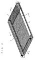
- FIG. 1 is a perspective view showing a configuration example of a dust-proof structure used in a projection image display device according to a first preferred embodiment of the present invention.
- FIG. 2 is a perspective view showing a configuration of a filter part provided in the dust-proof structure.
- An image display device part (not shown), the dust-proof structure shown in FIG. 1 , and an air sending fan 6 are arranged inside a casing (not shown) of the projection image display device.
- the dust-proof structure includes a filter frame 1, a drive mechanism 4, and a dust removal brush 5.
- the filter frame 1 is formed into a hollow loop shape having first and second surfaces facing each other.
- the first and second surfaces of the filter frame 1 respectively have rectangle shapes when seen in plan, and a section by line A-A of the filter frame 1 has an oval shape.
- a filter material (can be regarded as a first filter material) 2 is arranged on the first surface forming a part of a loop-shaped surface (refer to FIG. 2 ).
- the filter frame 1 is formed by a loop-shaped net band.
- the filter material 2 is not provided but a ventilation part 3 for reducing air resistance from a suction port of the casing is provided (refer to FIGS. 1 and 2 ).
- the ventilation part 3 faces the filter material 2, and further faces the air sending fan 6.
- the filter material 2 filters dust in external air taken from the suction port of the casing into the casing.
- the air after filtering the dust passes through a hollow part of the filter frame 1, and passes through the ventilation part 3 facing the filter material 2.
- the air passing through the ventilation part 3 is sent by the air sending fan 6 to a cooling target (the image display device part) inside the casing as cooling air.
- the filter frame 1 is connected to the drive mechanism 4, and teeth 1A meshed with a gear of the drive mechanism 4 are arranged in an inner periphery of a terminal end of the filter frame 1.
- Mechanical power transmitted from the gear of the drive mechanism 4 is transmitted to the teeth 1A of the filter frame 1, so that the filter frame 1 is rotated only in one direction (refer to arrows in FIG. 2 ).
- the surface forming the filter frame 1 (the surface forming the loop shape) is rotated only in one direction like a conveyor belt (refer to the arrows shown in FIG. 2 ).
- the dust removal brush 5 is arranged on the side of one edge of the filter frame 1.
- the dust removal brush 5 externally has a roll shape, and is fixed at a predetermined position.
- the dust removal brush 5 is brought into contact with the filter material 2 (the filter frame 1) while spinning on a spinning shaft 5A serving as an axis in the direction of the roll shape.
- the dust removal brush 5 removes the dust attached onto the filter material 2 in a part in contact with the filter material 2.
- the filter material 2 is desirably a mesh material.
- the drive mechanism 4 by limiting the direction of rotating the filter frame 1 by the drive mechanism 4 only to one direction, the number of parts forming the drive mechanism 4 is reduced, so that an effect of reducing cost can also be obtained.
- FIG. 3 is a perspective view showing a configuration example of a dust-proof structure used in a projection image display device according to a second preferred embodiment of the present invention.
- a detaching unit 7 and a dust box 8 are additionally formed in the configuration shown in the first preferred embodiment.
- the detaching unit 7 and the dust box 8 are shown in an exploded perspective view in FIG. 3 .
- the detaching unit 7 for detaching the dust attached onto the dust removal brush 5 is arranged on the side of the dust removal brush 5 where the dust removal brush is not in contact with the filter material 2.
- the dust box 8 storing the dust detached by the detaching unit 7 is arranged.
- the detaching unit 7 When for example a plate shape member serving as a scraper is provided as the detaching unit 7, a unit capable of detaching the dust attached onto the dust removal brush 5 can be realized with an inexpensive and simple structure. Alternatively, when a member having a charging effect is used as the detaching unit 7, a higher detaching effect can be expected.
- the detaching unit 7 and the dust box 8 are combined with each other.
- the dust removal brush 5 spins on the spinning shaft 5A serving as the axis.
- a part of the dust removal brush 5 is in contact with the filter frame 1 as shown in FIG. 3
- the dust removal brush 5 is in contact with the detaching unit 7 on the other side of a part in contact with the filter frame 1.
- the detaching unit 7 is fixed at the predetermined position, and brought into contact with the entire face of the dust removal brush 5 due to rotation of the dust removal-brush 5.
- the dust attached onto the dust removal brush 5 can be removed, so that the dust can be suppressed from being attached onto the filter material 2 again.
- the dust box 8 By additionally forming the dust box 8, the dust detached by the detaching unit 7 can be stored. Therefore, since the number of cleaning by the user can be reduced to a large extent, the maintenance is easily performed.
- the dust box 8 is independently separable, an operation at the time of the maintenance (such as an operation of removing the dust stored in the dust box 8) is easily performed.
- FIG. 4 is a perspective view showing a configuration example of a dust-proof structure used in a projection image display device according to a third preferred embodiment of the present invention.
- another filter material 9 is additionally formed in the configuration shown in the second preferred embodiment.
- the filter material 2 filters the external air taken into the casing.
- the mesh material is desirably used as the filter material 2.
- the mesh material is inferior in a dust collecting ability compared to non-woven fabric or the like.
- a filter material (can be regarded as a second filter material) 9 is additionally provided between the rotated filter frame 1 and the air sending fan 6.
- the additional filter material 9 is installed and fixed at the position described above.
- the additional filter material 9 is a filter capable of catching smaller dust than the filter material 2.
- the external air can be doubly filtered, so that dust-proof performance is improved. Further, in the invention according to the present preferred embodiment, even in a case where the external air is not filtered by the filter material 2 due to the rotation and the movement of the filter frame 1, the external air can be filtered by existence of the additional filter material 9.
- the additional filter material 9 is desirably a material capable of catching smaller dust than the filter material 2.
- a charging material is more desirably used as the additional filter material 9 for absorbing the dust.
- the additional filter material 9 is added to the configuration shown in FIG. 3 .
- the additional filter material 9 according to the present preferred embodiment may be additionally formed in the configuration shown in FIG. 1 as a matter of course.
- FIG. 5 is a view showing a configuration example of a dust-proof structure used in a projection image display device according to a fourth preferred embodiment of the present invention. Specifically, a part of the filter frame 1 is enlarged and shown in FIG. 5 .
- the filter frame 1 is rotated by the drive mechanism 4.
- a position detecting unit for detecting a moving amount by the rotation and the movement and detecting that the filter frame 1 is rotated and returned to a predetermined position.
- the filter frame 1 can be returned to a regular position (that is, the filter material 2 is positioned so as to face the suction port of the casing, and the ventilation part 3 is positioned between the filter material 2 and the air sending fan 6), so that displacement of the filter material 2 from the regular position after the rotation and the movement can be prevented.
- a cutout 10 is provided in a part of the rotated filter frame 1 as the position detecting unit.
- a photo interrupter can be regarded as an optical detector for optically detecting the cutout 10 is provided as the position detecting unit.
- a magnetic body may be arranged in a part of the filter frame 1 as the position detecting unit instead of the cutout 10.
- a magnetic sensor for detecting that the magnetic body is at a predetermined position is provided as the position detecting unit.
Landscapes
- Physics & Mathematics (AREA)
- General Physics & Mathematics (AREA)
- Projection Apparatus (AREA)
- Transforming Electric Information Into Light Information (AREA)
- Video Image Reproduction Devices For Color Tv Systems (AREA)
Claims (9)
- Ein Projektionsbild-Anzeigegerät mit:einem Gehäuse in dem ein Bildanzeigegeräteteil angeordnet ist;einem ersten Filtermaterial (2) zum Filtern von externer, in das Gehäuse gelangter Luft;einem Filterrahmen in Schleifengestalt (1) auf dem besagtes erstes Filtermaterial angebracht ist, wobei der Filterrahmen erste und zweite Flächen, die sich gegenüber liegen, aufweist; undeinem Antriebsmechanismus (4) zum Drehen des Filterrahmens in der Schleifenrichtung von besagter Schleifengestalt;gekennzeichnet durch
eine Staubentfernungsbürste (5), die während des Drehens an einer vorbestimmten Position in Kontakt mit besagtem ersten Filtermaterial zu bringen ist, wobei besagtes erstes Filtermaterial auf besagter erster Fläche von besagtem Filterrahmen angebracht ist und in besagter zweiter Fläche von besagtem Filterrahmen besagtes erstes Filtermaterial nicht angebracht ist, sondern ein Lüftungsteil (3) vorgesehen ist; und
darüber hinaus durch eine Positionserfassungseinheit, die dazu ausgebildet ist, zu erfassen, dass besagter Filterrahmen gedreht ist und zu einer vorbestimmten Position zurückgekehrt ist. - Das Projektionsbild-Anzeigegerät gemäß Anspruch 1, dadurch gekennzeichnet, dass besagte Positionserfassungseinheit beinhaltet:eine Aussparung (10), die in einem Teil des Filterrahmens vorgesehen ist; undeinen optischen Detektor zum optischen Erfassen von besagter Aussparung.
- Das Projektionsbild-Anzeigegerät gemäß Anspruch 1, dadurch gekennzeichnet, dass besagte Positionserfassungseinheit beinhaltet:einen Magnetkörper, der in einem Teil von besagtem Filterrahmen vorgesehen ist; undeinen magnetischen Sensor zum Erfassen von besagtem Magnetkörper.
- Das Projektionsbild-Anzeigegerät gemäß Anspruch 1, dadurch gekennzeichnet, dass besagter Filterrahmen durch ein Netzband in Schleifengestalt ausgebildet ist.
- Das Projektionsbild-Anzeigegerät gemäß Anspruch 1, dadurch gekennzeichnet, dass besagter Antriebsmechanismus besagten Filterrahmen lediglich in eine Richtung dreht.
- Das Projektionsbild-Anzeigegerät gemäß Anspruch 1, dadurch gekennzeichnet, dass es darüber hinaus umfasst:einen luftliefernden Lüfter (6) zum Liefern der externen Luft, die durch besagtes erstes Filtermaterial in besagtes Gehäuse gelangt.
- Das Projektionsbild-Anzeigegerät gemäß Anspruch 1, dadurch gekennzeichnet, dass es darüber hinaus umfasst:eine Abzieheinheit (7), die auf einer Seite von besagter Staubentfernungsbürste vorgesehen ist, wo besagte Staubentfernungsbürste nicht in Kontakt mit besagtem ersten Filtermaterial steht, wobei die Abzieheinheit zum Entfernen von Staub ist, der auf besagter Staubentfernungsbrüste anhaftet; undeinen Staubbehälter (8) zum Sammeln des von besagter Abzieheinheit entfernten Staubs.
- Das Projektionsbild-Anzeigegerät gemäß Anspruch 1, dadurch gekennzeichnet, dass es darüber hinaus umfasst:ein zweites Filtermaterial (9), das zwischen besagtem ersten Filtermaterial und besagtem luftlieferenden Lüfter vorgesehen ist.
- Das Projektionsbild-Anzeigegerät gemäß Anspruch 8, dadurch gekennzeichnet, dass besagtes zweites Filtermaterial zum Fangen von kleinerem Staub befähigt ist als besagtes erstes Filtermaterial.
Applications Claiming Priority (1)
| Application Number | Priority Date | Filing Date | Title |
|---|---|---|---|
| JP2010043958A JP5388901B2 (ja) | 2010-03-01 | 2010-03-01 | 投射型映像表示装置 |
Publications (2)
| Publication Number | Publication Date |
|---|---|
| EP2363747A1 EP2363747A1 (de) | 2011-09-07 |
| EP2363747B1 true EP2363747B1 (de) | 2013-11-27 |
Family
ID=43897074
Family Applications (1)
| Application Number | Title | Priority Date | Filing Date |
|---|---|---|---|
| EP11000721.8A Not-in-force EP2363747B1 (de) | 2010-03-01 | 2011-01-28 | Projektionsbildanzeigevorrichtung |
Country Status (4)
| Country | Link |
|---|---|
| US (1) | US8388144B2 (de) |
| EP (1) | EP2363747B1 (de) |
| JP (1) | JP5388901B2 (de) |
| CN (2) | CN103885272B (de) |
Families Citing this family (5)
| Publication number | Priority date | Publication date | Assignee | Title |
|---|---|---|---|---|
| JP5574833B2 (ja) * | 2010-06-08 | 2014-08-20 | 三洋電機株式会社 | フィルターユニット及び投写型映像表示装置 |
| CN103197495B (zh) * | 2012-01-04 | 2015-06-10 | 中强光电股份有限公司 | 气体过滤模块及投影装置 |
| JP2014209183A (ja) * | 2013-03-27 | 2014-11-06 | セイコーエプソン株式会社 | エアフィルター及びプロジェクター |
| CN109152289B (zh) * | 2018-09-03 | 2020-08-28 | 广州创慧信息科技股份有限公司 | 一种机房视频监控报警装置 |
| CN110955100B (zh) * | 2019-12-13 | 2022-01-28 | 深圳市杰奇科技创新有限公司 | 一种利于离心力原理的投影仪散热防尘装置 |
Family Cites Families (21)
| Publication number | Priority date | Publication date | Assignee | Title |
|---|---|---|---|---|
| JPS60171335A (ja) * | 1984-02-14 | 1985-09-04 | Matsushita Electric Ind Co Ltd | 空気調和機のエアフイルタ掃除装置 |
| JPS63130116A (ja) * | 1986-11-19 | 1988-06-02 | Mitsubishi Electric Corp | 空気調和機のフイルタ清掃装置 |
| JPH03213919A (ja) | 1990-01-19 | 1991-09-19 | Mitsubishi Electric Corp | 空気調和機のフイルタ清掃装置 |
| JP2653280B2 (ja) * | 1991-09-03 | 1997-09-17 | ダイキン工業株式会社 | オゾン脱臭装置 |
| JPH0659247A (ja) | 1992-08-11 | 1994-03-04 | Matsushita Electric Ind Co Ltd | 投写型画像表示装置 |
| JPH0674521A (ja) | 1992-08-21 | 1994-03-15 | Matsushita Electric Ind Co Ltd | 空気調和装置 |
| JPH06341665A (ja) * | 1993-06-01 | 1994-12-13 | Daikin Ind Ltd | ロールフィルタの巻取制御機構 |
| JPH08152242A (ja) * | 1994-11-29 | 1996-06-11 | Sony Corp | エアフィルタ交換装置 |
| JP3407576B2 (ja) * | 1997-01-09 | 2003-05-19 | 松下電器産業株式会社 | 投射型液晶表示装置の防塵構造 |
| JP2001337390A (ja) * | 2000-05-25 | 2001-12-07 | Matsushita Electric Ind Co Ltd | カラーホイールとそれを用いた色順次カラー表示装置 |
| CN1582838A (zh) * | 2003-08-21 | 2005-02-23 | 张周新 | 吸尘器的空气回流装置 |
| CN1612033A (zh) * | 2003-10-31 | 2005-05-04 | 明基电通股份有限公司 | 过滤装置 |
| JP3989461B2 (ja) * | 2004-05-06 | 2007-10-10 | 三洋電機株式会社 | 電気掃除機 |
| JP2007170782A (ja) | 2005-12-26 | 2007-07-05 | Daikin Ind Ltd | 自動フィルタ清掃装置及び空気調和装置 |
| JP2007333365A (ja) * | 2006-05-15 | 2007-12-27 | Daikin Ind Ltd | 空気調和機 |
| JP4896636B2 (ja) | 2006-09-01 | 2012-03-14 | 株式会社コーワ | 空気調和機用清掃装置と空気調和機 |
| JP4724752B2 (ja) * | 2007-01-26 | 2011-07-13 | パナソニック株式会社 | 粉塵捕捉装置および投写型画像表示装置 |
| JP4910744B2 (ja) | 2007-02-09 | 2012-04-04 | ダイキン工業株式会社 | 空気調和装置の室内ユニット |
| JP4952299B2 (ja) * | 2007-02-28 | 2012-06-13 | ダイキン工業株式会社 | 空気調和装置の室内ユニット |
| JP2009217105A (ja) * | 2008-03-12 | 2009-09-24 | Seiko Epson Corp | プロジェクタ |
| CN101576702B (zh) * | 2008-05-08 | 2011-06-15 | 三洋科技中心(深圳)有限公司 | 防尘组件及采用该防尘组件的投影装置 |
-
2010
- 2010-03-01 JP JP2010043958A patent/JP5388901B2/ja not_active Expired - Fee Related
-
2011
- 2011-01-28 EP EP11000721.8A patent/EP2363747B1/de not_active Not-in-force
- 2011-02-09 US US13/024,092 patent/US8388144B2/en not_active Expired - Fee Related
- 2011-02-28 CN CN201410090159.7A patent/CN103885272B/zh not_active Expired - Fee Related
- 2011-02-28 CN CN201110047909.9A patent/CN102193288A/zh active Pending
Also Published As
| Publication number | Publication date |
|---|---|
| US8388144B2 (en) | 2013-03-05 |
| CN103885272B (zh) | 2016-07-06 |
| CN102193288A (zh) | 2011-09-21 |
| JP2011180335A (ja) | 2011-09-15 |
| US20110211172A1 (en) | 2011-09-01 |
| EP2363747A1 (de) | 2011-09-07 |
| CN103885272A (zh) | 2014-06-25 |
| JP5388901B2 (ja) | 2014-01-15 |
Similar Documents
| Publication | Publication Date | Title |
|---|---|---|
| EP2363747B1 (de) | Projektionsbildanzeigevorrichtung | |
| US9091456B2 (en) | Indoor unit of air conditioner | |
| JP2005083721A (ja) | 空気調和機 | |
| JP4724752B2 (ja) | 粉塵捕捉装置および投写型画像表示装置 | |
| JP5276166B2 (ja) | 空気調和機 | |
| US20070207721A1 (en) | Electronic device and filtering unit | |
| US8696138B2 (en) | Filter unit and video projector | |
| JP5352950B2 (ja) | プロジェクター装置 | |
| JP2011257548A (ja) | エアフィルタ装置及びこれを用いた投写型映像表示装置 | |
| JP5627066B2 (ja) | 巻き取り式エアーフィルター機構及びプロジェクター装置 | |
| CN114137785A (zh) | 一种网络直播用数字放影机 | |
| JP2005083612A (ja) | 空気調和機 | |
| JP2008170808A (ja) | 集塵機構並びに投射型映像表示装置及び電子機器 | |
| JP4968942B2 (ja) | 撮像装置 | |
| JP2011050962A (ja) | 空気調和機 | |
| JP5593845B2 (ja) | フィルタ掃除機構、フィルタユニット、光学ユニットおよび投写型映像表示装置 | |
| JP2010230244A (ja) | 空気調和機 | |
| JP2011245461A (ja) | フィルタ掃除機構、フィルタユニット、光学ユニットおよび投写型映像表示装置 | |
| JP5679265B2 (ja) | エアーフィルター清掃機構及びプロジェクター装置 | |
| JP2012151298A (ja) | フィルタユニットを具えた電気機器 | |
| JP5176828B2 (ja) | 粉塵捕捉装置および投写型画像表示装置 | |
| JP5394703B2 (ja) | 粉塵捕捉装置および投写型画像表示装置 | |
| JP5195526B2 (ja) | プロジェクター | |
| JP2010104961A (ja) | 巻き取り式エアーフィルター清掃機構及びプロジェクター装置 | |
| JP2011149588A (ja) | 空気調和機のフィルター装置 |
Legal Events
| Date | Code | Title | Description |
|---|---|---|---|
| PUAI | Public reference made under article 153(3) epc to a published international application that has entered the european phase |
Free format text: ORIGINAL CODE: 0009012 |
|
| AK | Designated contracting states |
Kind code of ref document: A1 Designated state(s): AL AT BE BG CH CY CZ DE DK EE ES FI FR GB GR HR HU IE IS IT LI LT LU LV MC MK MT NL NO PL PT RO RS SE SI SK SM TR |
|
| AX | Request for extension of the european patent |
Extension state: BA ME |
|
| 17P | Request for examination filed |
Effective date: 20110831 |
|
| RIC1 | Information provided on ipc code assigned before grant |
Ipc: G03B 21/16 20060101AFI20130510BHEP |
|
| GRAP | Despatch of communication of intention to grant a patent |
Free format text: ORIGINAL CODE: EPIDOSNIGR1 |
|
| INTG | Intention to grant announced |
Effective date: 20130621 |
|
| GRAS | Grant fee paid |
Free format text: ORIGINAL CODE: EPIDOSNIGR3 |
|
| GRAA | (expected) grant |
Free format text: ORIGINAL CODE: 0009210 |
|
| AK | Designated contracting states |
Kind code of ref document: B1 Designated state(s): AL AT BE BG CH CY CZ DE DK EE ES FI FR GB GR HR HU IE IS IT LI LT LU LV MC MK MT NL NO PL PT RO RS SE SI SK SM TR |
|
| REG | Reference to a national code |
Ref country code: GB Ref legal event code: FG4D |
|
| REG | Reference to a national code |
Ref country code: CH Ref legal event code: EP |
|
| REG | Reference to a national code |
Ref country code: DE Ref legal event code: R082 Ref document number: 602011003903 Country of ref document: DE Representative=s name: PFENNING, MEINIG & PARTNER MBB PATENTANWAELTE, DE Ref country code: DE Ref legal event code: R082 Ref document number: 602011003903 Country of ref document: DE Representative=s name: PFENNING MEINIG & PARTNER GBR, DE |
|
| REG | Reference to a national code |
Ref country code: AT Ref legal event code: REF Ref document number: 642949 Country of ref document: AT Kind code of ref document: T Effective date: 20131215 |
|
| REG | Reference to a national code |
Ref country code: IE Ref legal event code: FG4D |
|
| REG | Reference to a national code |
Ref country code: DE Ref legal event code: R096 Ref document number: 602011003903 Country of ref document: DE Effective date: 20140123 |
|
| REG | Reference to a national code |
Ref country code: NL Ref legal event code: VDEP Effective date: 20131127 |
|
| REG | Reference to a national code |
Ref country code: AT Ref legal event code: MK05 Ref document number: 642949 Country of ref document: AT Kind code of ref document: T Effective date: 20131127 |
|
| REG | Reference to a national code |
Ref country code: LT Ref legal event code: MG4D |
|
| PG25 | Lapsed in a contracting state [announced via postgrant information from national office to epo] |
Ref country code: IS Free format text: LAPSE BECAUSE OF FAILURE TO SUBMIT A TRANSLATION OF THE DESCRIPTION OR TO PAY THE FEE WITHIN THE PRESCRIBED TIME-LIMIT Effective date: 20140327 Ref country code: NL Free format text: LAPSE BECAUSE OF FAILURE TO SUBMIT A TRANSLATION OF THE DESCRIPTION OR TO PAY THE FEE WITHIN THE PRESCRIBED TIME-LIMIT Effective date: 20131127 Ref country code: LT Free format text: LAPSE BECAUSE OF FAILURE TO SUBMIT A TRANSLATION OF THE DESCRIPTION OR TO PAY THE FEE WITHIN THE PRESCRIBED TIME-LIMIT Effective date: 20131127 Ref country code: FI Free format text: LAPSE BECAUSE OF FAILURE TO SUBMIT A TRANSLATION OF THE DESCRIPTION OR TO PAY THE FEE WITHIN THE PRESCRIBED TIME-LIMIT Effective date: 20131127 Ref country code: SE Free format text: LAPSE BECAUSE OF FAILURE TO SUBMIT A TRANSLATION OF THE DESCRIPTION OR TO PAY THE FEE WITHIN THE PRESCRIBED TIME-LIMIT Effective date: 20131127 Ref country code: NO Free format text: LAPSE BECAUSE OF FAILURE TO SUBMIT A TRANSLATION OF THE DESCRIPTION OR TO PAY THE FEE WITHIN THE PRESCRIBED TIME-LIMIT Effective date: 20140227 Ref country code: HR Free format text: LAPSE BECAUSE OF FAILURE TO SUBMIT A TRANSLATION OF THE DESCRIPTION OR TO PAY THE FEE WITHIN THE PRESCRIBED TIME-LIMIT Effective date: 20131127 |
|
| PG25 | Lapsed in a contracting state [announced via postgrant information from national office to epo] |
Ref country code: BE Free format text: LAPSE BECAUSE OF FAILURE TO SUBMIT A TRANSLATION OF THE DESCRIPTION OR TO PAY THE FEE WITHIN THE PRESCRIBED TIME-LIMIT Effective date: 20131127 Ref country code: ES Free format text: LAPSE BECAUSE OF FAILURE TO SUBMIT A TRANSLATION OF THE DESCRIPTION OR TO PAY THE FEE WITHIN THE PRESCRIBED TIME-LIMIT Effective date: 20131127 Ref country code: RS Free format text: LAPSE BECAUSE OF FAILURE TO SUBMIT A TRANSLATION OF THE DESCRIPTION OR TO PAY THE FEE WITHIN THE PRESCRIBED TIME-LIMIT Effective date: 20131127 Ref country code: CY Free format text: LAPSE BECAUSE OF FAILURE TO SUBMIT A TRANSLATION OF THE DESCRIPTION OR TO PAY THE FEE WITHIN THE PRESCRIBED TIME-LIMIT Effective date: 20131127 Ref country code: LV Free format text: LAPSE BECAUSE OF FAILURE TO SUBMIT A TRANSLATION OF THE DESCRIPTION OR TO PAY THE FEE WITHIN THE PRESCRIBED TIME-LIMIT Effective date: 20131127 Ref country code: AT Free format text: LAPSE BECAUSE OF FAILURE TO SUBMIT A TRANSLATION OF THE DESCRIPTION OR TO PAY THE FEE WITHIN THE PRESCRIBED TIME-LIMIT Effective date: 20131127 |
|
| PG25 | Lapsed in a contracting state [announced via postgrant information from national office to epo] |
Ref country code: PT Free format text: LAPSE BECAUSE OF FAILURE TO SUBMIT A TRANSLATION OF THE DESCRIPTION OR TO PAY THE FEE WITHIN THE PRESCRIBED TIME-LIMIT Effective date: 20140327 |
|
| PG25 | Lapsed in a contracting state [announced via postgrant information from national office to epo] |
Ref country code: EE Free format text: LAPSE BECAUSE OF FAILURE TO SUBMIT A TRANSLATION OF THE DESCRIPTION OR TO PAY THE FEE WITHIN THE PRESCRIBED TIME-LIMIT Effective date: 20131127 |
|
| REG | Reference to a national code |
Ref country code: DE Ref legal event code: R097 Ref document number: 602011003903 Country of ref document: DE |
|
| PG25 | Lapsed in a contracting state [announced via postgrant information from national office to epo] |
Ref country code: LU Free format text: LAPSE BECAUSE OF FAILURE TO SUBMIT A TRANSLATION OF THE DESCRIPTION OR TO PAY THE FEE WITHIN THE PRESCRIBED TIME-LIMIT Effective date: 20140128 Ref country code: PL Free format text: LAPSE BECAUSE OF FAILURE TO SUBMIT A TRANSLATION OF THE DESCRIPTION OR TO PAY THE FEE WITHIN THE PRESCRIBED TIME-LIMIT Effective date: 20131127 Ref country code: RO Free format text: LAPSE BECAUSE OF FAILURE TO SUBMIT A TRANSLATION OF THE DESCRIPTION OR TO PAY THE FEE WITHIN THE PRESCRIBED TIME-LIMIT Effective date: 20131127 Ref country code: CZ Free format text: LAPSE BECAUSE OF FAILURE TO SUBMIT A TRANSLATION OF THE DESCRIPTION OR TO PAY THE FEE WITHIN THE PRESCRIBED TIME-LIMIT Effective date: 20131127 Ref country code: SK Free format text: LAPSE BECAUSE OF FAILURE TO SUBMIT A TRANSLATION OF THE DESCRIPTION OR TO PAY THE FEE WITHIN THE PRESCRIBED TIME-LIMIT Effective date: 20131127 |
|
| REG | Reference to a national code |
Ref country code: CH Ref legal event code: PL |
|
| PG25 | Lapsed in a contracting state [announced via postgrant information from national office to epo] |
Ref country code: DK Free format text: LAPSE BECAUSE OF FAILURE TO SUBMIT A TRANSLATION OF THE DESCRIPTION OR TO PAY THE FEE WITHIN THE PRESCRIBED TIME-LIMIT Effective date: 20131127 |
|
| PLBE | No opposition filed within time limit |
Free format text: ORIGINAL CODE: 0009261 |
|
| STAA | Information on the status of an ep patent application or granted ep patent |
Free format text: STATUS: NO OPPOSITION FILED WITHIN TIME LIMIT |
|
| PG25 | Lapsed in a contracting state [announced via postgrant information from national office to epo] |
Ref country code: CH Free format text: LAPSE BECAUSE OF NON-PAYMENT OF DUE FEES Effective date: 20140131 Ref country code: LI Free format text: LAPSE BECAUSE OF NON-PAYMENT OF DUE FEES Effective date: 20140131 |
|
| 26N | No opposition filed |
Effective date: 20140828 |
|
| REG | Reference to a national code |
Ref country code: IE Ref legal event code: MM4A |
|
| REG | Reference to a national code |
Ref country code: DE Ref legal event code: R097 Ref document number: 602011003903 Country of ref document: DE Effective date: 20140828 |
|
| PG25 | Lapsed in a contracting state [announced via postgrant information from national office to epo] |
Ref country code: IE Free format text: LAPSE BECAUSE OF NON-PAYMENT OF DUE FEES Effective date: 20140128 |
|
| PG25 | Lapsed in a contracting state [announced via postgrant information from national office to epo] |
Ref country code: SI Free format text: LAPSE BECAUSE OF FAILURE TO SUBMIT A TRANSLATION OF THE DESCRIPTION OR TO PAY THE FEE WITHIN THE PRESCRIBED TIME-LIMIT Effective date: 20131127 |
|
| PG25 | Lapsed in a contracting state [announced via postgrant information from national office to epo] |
Ref country code: MC Free format text: LAPSE BECAUSE OF FAILURE TO SUBMIT A TRANSLATION OF THE DESCRIPTION OR TO PAY THE FEE WITHIN THE PRESCRIBED TIME-LIMIT Effective date: 20131127 |
|
| REG | Reference to a national code |
Ref country code: FR Ref legal event code: PLFP Year of fee payment: 6 |
|
| PG25 | Lapsed in a contracting state [announced via postgrant information from national office to epo] |
Ref country code: MT Free format text: LAPSE BECAUSE OF FAILURE TO SUBMIT A TRANSLATION OF THE DESCRIPTION OR TO PAY THE FEE WITHIN THE PRESCRIBED TIME-LIMIT Effective date: 20131127 |
|
| PG25 | Lapsed in a contracting state [announced via postgrant information from national office to epo] |
Ref country code: SM Free format text: LAPSE BECAUSE OF FAILURE TO SUBMIT A TRANSLATION OF THE DESCRIPTION OR TO PAY THE FEE WITHIN THE PRESCRIBED TIME-LIMIT Effective date: 20131127 |
|
| PG25 | Lapsed in a contracting state [announced via postgrant information from national office to epo] |
Ref country code: GR Free format text: LAPSE BECAUSE OF FAILURE TO SUBMIT A TRANSLATION OF THE DESCRIPTION OR TO PAY THE FEE WITHIN THE PRESCRIBED TIME-LIMIT Effective date: 20140228 Ref country code: BG Free format text: LAPSE BECAUSE OF FAILURE TO SUBMIT A TRANSLATION OF THE DESCRIPTION OR TO PAY THE FEE WITHIN THE PRESCRIBED TIME-LIMIT Effective date: 20131127 Ref country code: IT Free format text: LAPSE BECAUSE OF FAILURE TO SUBMIT A TRANSLATION OF THE DESCRIPTION OR TO PAY THE FEE WITHIN THE PRESCRIBED TIME-LIMIT Effective date: 20131127 |
|
| PG25 | Lapsed in a contracting state [announced via postgrant information from national office to epo] |
Ref country code: TR Free format text: LAPSE BECAUSE OF FAILURE TO SUBMIT A TRANSLATION OF THE DESCRIPTION OR TO PAY THE FEE WITHIN THE PRESCRIBED TIME-LIMIT Effective date: 20131127 Ref country code: HU Free format text: LAPSE BECAUSE OF FAILURE TO SUBMIT A TRANSLATION OF THE DESCRIPTION OR TO PAY THE FEE WITHIN THE PRESCRIBED TIME-LIMIT; INVALID AB INITIO Effective date: 20110128 |
|
| REG | Reference to a national code |
Ref country code: FR Ref legal event code: PLFP Year of fee payment: 7 |
|
| PGFP | Annual fee paid to national office [announced via postgrant information from national office to epo] |
Ref country code: FR Payment date: 20161215 Year of fee payment: 7 |
|
| PGFP | Annual fee paid to national office [announced via postgrant information from national office to epo] |
Ref country code: DE Payment date: 20170125 Year of fee payment: 7 |
|
| PGFP | Annual fee paid to national office [announced via postgrant information from national office to epo] |
Ref country code: GB Payment date: 20170125 Year of fee payment: 7 |
|
| PG25 | Lapsed in a contracting state [announced via postgrant information from national office to epo] |
Ref country code: MK Free format text: LAPSE BECAUSE OF FAILURE TO SUBMIT A TRANSLATION OF THE DESCRIPTION OR TO PAY THE FEE WITHIN THE PRESCRIBED TIME-LIMIT Effective date: 20131127 |
|
| REG | Reference to a national code |
Ref country code: DE Ref legal event code: R119 Ref document number: 602011003903 Country of ref document: DE |
|
| GBPC | Gb: european patent ceased through non-payment of renewal fee |
Effective date: 20180128 |
|
| PG25 | Lapsed in a contracting state [announced via postgrant information from national office to epo] |
Ref country code: DE Free format text: LAPSE BECAUSE OF NON-PAYMENT OF DUE FEES Effective date: 20180801 Ref country code: AL Free format text: LAPSE BECAUSE OF FAILURE TO SUBMIT A TRANSLATION OF THE DESCRIPTION OR TO PAY THE FEE WITHIN THE PRESCRIBED TIME-LIMIT Effective date: 20131127 Ref country code: FR Free format text: LAPSE BECAUSE OF NON-PAYMENT OF DUE FEES Effective date: 20180131 |
|
| REG | Reference to a national code |
Ref country code: FR Ref legal event code: ST Effective date: 20180928 |
|
| PG25 | Lapsed in a contracting state [announced via postgrant information from national office to epo] |
Ref country code: GB Free format text: LAPSE BECAUSE OF NON-PAYMENT OF DUE FEES Effective date: 20180128 |