EP2363580A2 - Joint de tige de vanne - Google Patents
Joint de tige de vanne Download PDFInfo
- Publication number
- EP2363580A2 EP2363580A2 EP11001487A EP11001487A EP2363580A2 EP 2363580 A2 EP2363580 A2 EP 2363580A2 EP 11001487 A EP11001487 A EP 11001487A EP 11001487 A EP11001487 A EP 11001487A EP 2363580 A2 EP2363580 A2 EP 2363580A2
- Authority
- EP
- European Patent Office
- Prior art keywords
- valve stem
- lip
- diameter
- guide
- pressure
- Prior art date
- Legal status (The legal status is an assumption and is not a legal conclusion. Google has not performed a legal analysis and makes no representation as to the accuracy of the status listed.)
- Granted
Links
- 238000000926 separation method Methods 0.000 abstract description 16
- 238000007789 sealing Methods 0.000 description 4
- 230000000694 effects Effects 0.000 description 2
- 230000004323 axial length Effects 0.000 description 1
- 230000012447 hatching Effects 0.000 description 1
- 238000000465 moulding Methods 0.000 description 1
- 230000002093 peripheral effect Effects 0.000 description 1
Images


Classifications
-
- F—MECHANICAL ENGINEERING; LIGHTING; HEATING; WEAPONS; BLASTING
- F01—MACHINES OR ENGINES IN GENERAL; ENGINE PLANTS IN GENERAL; STEAM ENGINES
- F01L—CYCLICALLY OPERATING VALVES FOR MACHINES OR ENGINES
- F01L3/00—Lift-valve, i.e. cut-off apparatus with closure members having at least a component of their opening and closing motion perpendicular to the closing faces; Parts or accessories thereof
- F01L3/08—Valves guides; Sealing of valve stem, e.g. sealing by lubricant
-
- F—MECHANICAL ENGINEERING; LIGHTING; HEATING; WEAPONS; BLASTING
- F16—ENGINEERING ELEMENTS AND UNITS; GENERAL MEASURES FOR PRODUCING AND MAINTAINING EFFECTIVE FUNCTIONING OF MACHINES OR INSTALLATIONS; THERMAL INSULATION IN GENERAL
- F16J—PISTONS; CYLINDERS; SEALINGS
- F16J15/00—Sealings
Definitions
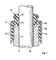
- the present invention relates to a valve stem seal which is a kind of a sealing device.
- a back pressure lip 53 is provided together with an oil lip 52 as a main lip, so that a variation in oil leakage amount may be suppressed by a sealing action of the back pressure lip 53.
- valve stem seal 51 of Fig. 3 is mounted in a manner of being fitted to an outer-diameter surface of a valve stem guide 54, an inner-diameter rubber portion 56 attached to an inner-diameter surface of a metallic ring 55 has a fitting margin set to have a diameter smaller than the outer diameter of the valve stem guide 54, and the inner-diameter rubber portion 56 encroaches on a guide groove 57 provided at the outer-diameter surface of the valve stem guide 54, thereby setting a holding force of the seal 51.
- a generated port pressure P enters a space D between the valve stem guide 54 and the back pressure lip 53 through a gap C between the valve stem guide 54 and the valve stem 58, and pressurizes the entire surface of the space D.
- the force for pressing the seal 51 upward may become larger than the holding force of the seal 51, and in this case, there is a concern that the seal 51 may be separated.
- the invention is made in view of such circumstances, and an object of the invention is to suppress occurrence of a separation of a seal in a valve stem seal including an oil lip and a back pressure lip and fitted to an outer-diameter portion of a valve stem guide.
- a valve stem seal that is mounted on a valve stem guide in which a valve stem is inserted through an inner-diameter shaft hole of a cylindrical portion, and a guide groove is formed in an outer-diameter surface of the cylindrical portion
- the valve stem seal including: a metallic ring which is disposed on the outer diameter side of the valve stem guide; a rubber-like elastic body which is attached to the metallic ring; and an inner-diameter rubber portion which is fitted to the outer-diameter surface of the valve stem guide together with an oil lip and a back pressure lip coming into close contact with the outer-diameter surface of the valve stem while having a predetermined fitting margin by the use of the rubber-like elastic body, wherein a pressure receiving lip engaging with the guide groove is provided in the inner-diameter surface of the inner-diameter rubber portion, and wherein a channel is provided in a portion between the back pressure lip and the pressure receiving
- a plurality of protrusion portions is formed evenly on the circumference of the portion between the back pressure lip and the pressure receiving lip of the inner-diameter rubber portion to be fitted to the outer-diameter surface of the valve stem guide while having a predetermined fitting margin, and the channel is formed by the relative concave portions between the adjacent protrusion portions.
- the whole circumference of a portion of the inner-diameter rubber portion located closer to a port side than the pressure receiving lip is fitted to the outer-diameter surface of the valve stem guide while having a predetermined fitting margin.
- the pressure receiving lip engaging with the guide groove is provided in the inner-diameter surface of the inner-diameter rubber portion, and the channel is provided in a portion between the back pressure lip and the pressure receiving lip of the inner-diameter rubber portion so as to guide a pressure which has entered from a gap between the valve stem guide and the valve stem to a space between the valve stem guide and the back pressure lip toward the pressure receiving lip. Accordingly, the pressure inside the space acts on the pressure receiving lip via the channel, and the pressure acting thereon acts as a force in the direction where the occurrence of the separation of the valve stem seal is suppressed. Further, since the pressure receiving lip engages with the guide groove, this engagement structure also acts to suppress the occurrence of the separation of the valve stem seal. Accordingly, with this configuration, the occurrence of the separation of the valve stem seal may be suppressed.
- the inner-diameter surface of the inner-diameter rubber portion may be provided with the plurality of protrusion portions provided evenly on the circumference and fitted to the outer-diameter surface of the valve stem guide with a predetermined fitting margin and the channel is formed by the relative concave portions between the adjacent protrusion portions.
- a force allowing the protrusion portion to be fitted to the outer-diameter surface of the valve stem guide with a predetermined fitting margin may be used as a part of a force for suppressing the occurrence of the separation of the valve stem seal.
- the plurality of protrusion portions is provided evenly on the circumference and is equally fitted to the circumference of the valve stem guide, a satisfactory balance is obtained on the circumference.
- the whole circumference of a portion of the inner-diameter rubber portion located closer to a port side than the pressure receiving lip may be fitted to the outer-diameter surface of the valve stem guide while having a predetermined fitting margin.
- the fitting force generated at this time may be used as a part of a force for suppressing the occurrence of the separation of the valve stem seal.
- a force for suppressing the occurrence of the separation of the valve stem seal may be set to be large with the above-described configuration, the occurrence of the separation of the valve stem seal may be effectively suppressed.
- valve stem guide has the guide groove at the outer-diameter surface thereof, since the valve stem seal of the invention may be mounted by directly using the valve stem guide, the existing facility may be directly utilized.
- the invention includes the following embodiment.
- the generated port pressure is made to be interposed in a space (a space at the side of oil of the pressure receiving lip) via another space (a space between the valve stem guide and the back pressure lip), and the pressure is sealed by the pressure receiving lip provided at the middle portion to have a force pressing the seal downward by the pressure and a force pressing the outer-diameter portion of the guide groove inward. Accordingly, the upward pressing force generated by the pressure of the space (the space between the valve stem guide and the back pressure lip) may be canceled or reduced, and the separation of the seal may be prevented even in the event of generation of high pressure.
- Fig. 1 is a half-cut cross-sectional view illustrating a valve stem seal 1 according to the embodiment of the invention, and Fig. 2 illustrates the mounted state thereof.
- the upper side of the drawing is the oil side
- the lower side is the port side.
- a back pressure lip 5 is depicted such that a part of the circumference is notched.
- the valve stem seal 1 is mounted on an outer-diameter portion of a valve stem guide 21 in which a valve stem 31 is inserted through an inner-diameter shaft hole of a cylindrical portion 22 so as to be slidable in the axial direction and an annular guide groove 23 is provided in the outer-diameter surface of the cylindrical portion 22, and includes a metallic ring (an attachment ring) 2 disposed at the outer diameter side of the valve stem guide 21 and a rubber-like elastic body 3 attached (cure-attached) to the metallic ring 2.
- an oil lip 4 and a back pressure lip 5 being in close contact with the outer-diameter surface of the valve stem 31 are integrally molded with an inner-diameter rubber portion 7 fitted to the outer-diameter surface of the valve stem guide 21 with a predetermined fitting margin.
- a flange portion 2b at the upper end of a cylindrical portion 2a of the metallic ring 2 to face the inside of the radial direction the oil lip 4 and the back pressure lip 5 are held by the inner-diameter portion of the flange portion 2b.
- a garter spring 6 is fitted to the oil lip 4 so as to adjust the fitting margin.
- the back pressure lip 5 is disposed at the lower side of the oil lip 4 such that a pressure receiving surface 5a faces the lower side.
- An annular pressure receiving lip 8 is integrally formed at the center in the axial direction of the inner-diameter surface of the inner-diameter rubber portion 7 so as to engage with the guide groove 23 in the axial direction, and the pressure receiving lip 8 is formed such that the pressure receiving surface 8a faces the upper side opposite to the side of the back pressure lip 5, that is, the inner-diameter portion is located to be closer to the upper side than the outer-diameter portion.
- the upper side surface of the guide groove 23 is formed in a plane shape that is perpendicular to the axial direction so that the pressure receiving lip 8 easily engages therewith.
- the inner-diameter surface formed in a cylindrical surface shape comes into close contact with the groove bottom surface of the guide groove 23 with a predetermined sealing surface pressure, thereby allowing the portion to exhibit a sealing action.
- a portion (an upper portion) 7a located between the back pressure lip 5 and the pressure receiving lip 8 in the inner-diameter rubber portion 7 is provided with a channel 9 which guides a pressure entering a space D between the back pressure lip 5 and the valve stem guide 21 via a gap C between the valve stem 31 and the valve stem guide 21 toward the pressure receiving lip 8.
- the channel 9 is formed in the inner-diameter surface of the upper portion 7a by the relative concave portions between adjacent protrusion portions 10, where a plurality of protrusion portions 10 is arranged evenly on the circumference and is fitted to (brought into close contact with) the outer-diameter surface of the valve stem guide 21 with a predetermined fitting margin.
- the even numbers are, for example, four even numbers, but the invention is not limited thereto.
- the axial lengths of the protrusion portion 10 and the channel 9 are denoted by a symbol L in Fig. 1 .
- the height of the protrusion portion 10, that is, the depth of the channel 9 is denoted by a symbol H in Fig. 1 .
- the portion having the cross-sections of the channel 9 and the protrusion 10 is not depicted by hatching.
- the protrusion portion 10 and the pressure receiving lip 8 provided in the inner-diameter surface of the inner-diameter rubber portion 7 are spaced from each other in the axial direction, that is, a predetermined axial gap E is set between both members 8 and 10.
- the inner-diameter surface is formed in a cylindrical surface shape, and the whole circumference surface is fitted to the outer-diameter surface of the valve stem guide 21 with a predetermined fitting margin.
- the inner diameter of the lower portion 7b is set to be equal or substantially equal to the inner diameter of the protrusion portion 10.
- valve stem seal 1 with the above-described configuration is mounted as shown in Fig. 2 . According to this structure, the following effect may be exhibited.
- the inner-diameter surface of the inner-diameter rubber portion 7 is provided with the pressure receiving lip 8 engaging with the guide groove 23 of the valve stem guide 21, and the inner-diameter surface of the upper portion 7a of the inner-diameter rubber portion 7 is provided with the channel 9 guiding a pressure.
- the pressure inside the space D acts on the pressure receiving lip 8 via the channel 9, and the pressure acting thereon acts as a force acting downward, that is, in the direction in which the separation of the seal 1 is suppressed, whereby a part of a force pushing the seal 1 upward is canceled out and the latter force is reduced.
- this engagement structure also acts to suppress the separation of the seal 1. Accordingly, with such a configuration, the occurrence of the separation of the seal 1 may be suppressed.
- the inner-diameter surface of the upper portion 7a of the inner-diameter rubber portion 7 is provided with the plurality of protrusion portions 10 arranged evenly on the circumference and fitted to the outer-diameter surface of the valve stem guide 21 with a predetermined fitting margin, and the channel 9 is provided at the relative concave portions between the adjacent protrusion portions 10.
- a force allowing the protrusion portion 10 to be fitted to the outer-diameter surface of the valve stem guide 21 with a predetermined fitting margin may be used as a part of a force for suppressing the occurrence of the separation of the seal 1. Since the plurality of protrusion portions 10 is provided evenly on the circumference and is equally fitted to the outer-diameter surface of the valve stem guide, a satisfactory balance is obtained on the circumference.
- the whole circumference surface thereof is fitted to the outer-diameter surface of the valve stem guide 21 with a predetermined fitting margin, and hence the fitting force generated at this time may be used as a part of a force for suppressing the occurrence of the separation of the seal 1.
Landscapes
- Engineering & Computer Science (AREA)
- General Engineering & Computer Science (AREA)
- Mechanical Engineering (AREA)
- Sealing With Elastic Sealing Lips (AREA)
- Check Valves (AREA)
Applications Claiming Priority (1)
| Application Number | Priority Date | Filing Date | Title |
|---|---|---|---|
| JP2010045101A JP5408443B2 (ja) | 2010-03-02 | 2010-03-02 | バルブステムシール |
Publications (3)
| Publication Number | Publication Date |
|---|---|
| EP2363580A2 true EP2363580A2 (fr) | 2011-09-07 |
| EP2363580A3 EP2363580A3 (fr) | 2012-09-26 |
| EP2363580B1 EP2363580B1 (fr) | 2013-06-05 |
Family
ID=44064814
Family Applications (1)
| Application Number | Title | Priority Date | Filing Date |
|---|---|---|---|
| EP11001487.5A Not-in-force EP2363580B1 (fr) | 2010-03-02 | 2011-02-23 | Joint de tige de vanne |
Country Status (2)
| Country | Link |
|---|---|
| EP (1) | EP2363580B1 (fr) |
| JP (1) | JP5408443B2 (fr) |
Cited By (2)
| Publication number | Priority date | Publication date | Assignee | Title |
|---|---|---|---|---|
| JPWO2017030060A1 (ja) * | 2015-08-20 | 2018-06-14 | Nok株式会社 | バルブステムシール及び密封構造 |
| AU2022201961B2 (en) * | 2021-04-01 | 2024-03-21 | Kabushiki Kaisha Toyota Jidoshokki | Valve Stem Seal Structure |
Families Citing this family (4)
| Publication number | Priority date | Publication date | Assignee | Title |
|---|---|---|---|---|
| WO2017099045A1 (fr) * | 2015-12-08 | 2017-06-15 | Nok株式会社 | Joint d'étanchéité de tige de vanne |
| JPWO2019131015A1 (ja) * | 2017-12-28 | 2020-11-19 | Nok株式会社 | 密封構造 |
| KR101992323B1 (ko) * | 2018-10-30 | 2019-06-25 | 평화오일씰공업 주식회사 | 더스트 씰 조립체 |
| KR102348131B1 (ko) * | 2019-09-04 | 2022-01-06 | 평화오일씰공업 주식회사 | 디링을 구비한 자동변속기 |
Citations (1)
| Publication number | Priority date | Publication date | Assignee | Title |
|---|---|---|---|---|
| JP2009264415A (ja) | 2008-04-22 | 2009-11-12 | Nok Corp | バルブステムシールの装着構造 |
Family Cites Families (10)
| Publication number | Priority date | Publication date | Assignee | Title |
|---|---|---|---|---|
| JPH0447369Y2 (fr) * | 1987-01-08 | 1992-11-09 | ||
| JPH0493569U (fr) * | 1990-12-28 | 1992-08-13 | ||
| DE4119952A1 (de) * | 1991-06-18 | 1992-12-24 | Goetze Ag | Ventilschaftabdichtung |
| JP4310596B2 (ja) * | 2000-03-14 | 2009-08-12 | Nok株式会社 | オイルシール |
| JP2007218282A (ja) * | 2006-02-14 | 2007-08-30 | Nok Corp | 密封装置 |
| JP2007298143A (ja) * | 2006-05-02 | 2007-11-15 | Nok Corp | オイルシール |
| JP4853636B2 (ja) * | 2006-08-04 | 2012-01-11 | Nok株式会社 | バルブステムシール |
| EP1939413B1 (fr) * | 2006-12-29 | 2010-07-21 | CORCOS INDUSTRIALE S.a.s. di Externa Italia S.r.l. | Ensemble de soupape pour moteur à combustion interne, comprenant une soupape et un joint positionné de manière coaxiale à ladite soupape |
| JP2009257509A (ja) * | 2008-04-18 | 2009-11-05 | Nok Corp | バルブステムシール |
| JP2009264449A (ja) * | 2008-04-23 | 2009-11-12 | Nok Corp | バルブステムシール |
-
2010
- 2010-03-02 JP JP2010045101A patent/JP5408443B2/ja active Active
-
2011
- 2011-02-23 EP EP11001487.5A patent/EP2363580B1/fr not_active Not-in-force
Patent Citations (1)
| Publication number | Priority date | Publication date | Assignee | Title |
|---|---|---|---|---|
| JP2009264415A (ja) | 2008-04-22 | 2009-11-12 | Nok Corp | バルブステムシールの装着構造 |
Cited By (4)
| Publication number | Priority date | Publication date | Assignee | Title |
|---|---|---|---|---|
| JPWO2017030060A1 (ja) * | 2015-08-20 | 2018-06-14 | Nok株式会社 | バルブステムシール及び密封構造 |
| EP3339695A4 (fr) * | 2015-08-20 | 2019-03-20 | Nok Corporation | Joint de tige de soupape et structure d'étanchéité |
| US10767519B2 (en) | 2015-08-20 | 2020-09-08 | Nok Corporation | Valve stem seal and hermetic sealing structure |
| AU2022201961B2 (en) * | 2021-04-01 | 2024-03-21 | Kabushiki Kaisha Toyota Jidoshokki | Valve Stem Seal Structure |
Also Published As
| Publication number | Publication date |
|---|---|
| JP2011179606A (ja) | 2011-09-15 |
| EP2363580B1 (fr) | 2013-06-05 |
| EP2363580A3 (fr) | 2012-09-26 |
| JP5408443B2 (ja) | 2014-02-05 |
Similar Documents
| Publication | Publication Date | Title |
|---|---|---|
| EP2363580B1 (fr) | Joint de tige de vanne | |
| US10612660B2 (en) | Gasket | |
| US6702293B2 (en) | Seal member mounted between cylinder head cover and ignition plug tube | |
| EP2341268B1 (fr) | Joint d'étanchéité | |
| KR20130095302A (ko) | 개스킷 | |
| CN108071804B (zh) | 用于旋转构件的密封组件 | |
| CN108368938B (zh) | 气门油封 | |
| US10767519B2 (en) | Valve stem seal and hermetic sealing structure | |
| EP2886803A1 (fr) | Joint pour moteurs de turbine à gaz | |
| US20190368551A1 (en) | Rolling boot comprising at least one reinforcement fin | |
| JP2015148335A (ja) | オイルシール | |
| EP2236867A1 (fr) | Dispositif d'étanchéité | |
| EP2236776A1 (fr) | Ventilschaftdichtung | |
| US10100881B2 (en) | Clutch seal | |
| EP2110521A1 (fr) | Dispositif d'obturation | |
| JP2010265937A (ja) | シールリング | |
| EP2730757B1 (fr) | Dispositif de joint pour tige de soupape | |
| WO2019041325A1 (fr) | Ensemble d'étanchéité de piston pour système de débrayage d'embrayage et système de débrayage d'embrayage | |
| JP2009024712A (ja) | 密封装置 | |
| JP2007303483A (ja) | ボンデット・ピストン・シール | |
| JP6534550B2 (ja) | バルブステムシール | |
| JP2014219044A (ja) | ブリーザ | |
| US12044314B2 (en) | Sealing device | |
| CN210661630U (zh) | 一种多重密封式唇形密封圈 | |
| JP6451864B2 (ja) | バルブステムシール及び密封構造 |
Legal Events
| Date | Code | Title | Description |
|---|---|---|---|
| PUAI | Public reference made under article 153(3) epc to a published international application that has entered the european phase |
Free format text: ORIGINAL CODE: 0009012 |
|
| AK | Designated contracting states |
Kind code of ref document: A2 Designated state(s): AL AT BE BG CH CY CZ DE DK EE ES FI FR GB GR HR HU IE IS IT LI LT LU LV MC MK MT NL NO PL PT RO RS SE SI SK SM TR |
|
| AX | Request for extension of the european patent |
Extension state: BA ME |
|
| PUAL | Search report despatched |
Free format text: ORIGINAL CODE: 0009013 |
|
| AK | Designated contracting states |
Kind code of ref document: A3 Designated state(s): AL AT BE BG CH CY CZ DE DK EE ES FI FR GB GR HR HU IE IS IT LI LT LU LV MC MK MT NL NO PL PT RO RS SE SI SK SM TR |
|
| AX | Request for extension of the european patent |
Extension state: BA ME |
|
| RIC1 | Information provided on ipc code assigned before grant |
Ipc: F01L 3/08 20060101AFI20120820BHEP |
|
| 17P | Request for examination filed |
Effective date: 20121017 |
|
| GRAP | Despatch of communication of intention to grant a patent |
Free format text: ORIGINAL CODE: EPIDOSNIGR1 |
|
| GRAS | Grant fee paid |
Free format text: ORIGINAL CODE: EPIDOSNIGR3 |
|
| GRAA | (expected) grant |
Free format text: ORIGINAL CODE: 0009210 |
|
| AK | Designated contracting states |
Kind code of ref document: B1 Designated state(s): AL AT BE BG CH CY CZ DE DK EE ES FI FR GB GR HR HU IE IS IT LI LT LU LV MC MK MT NL NO PL PT RO RS SE SI SK SM TR |
|
| REG | Reference to a national code |
Ref country code: GB Ref legal event code: FG4D |
|
| REG | Reference to a national code |
Ref country code: CH Ref legal event code: EP |
|
| REG | Reference to a national code |
Ref country code: AT Ref legal event code: REF Ref document number: 615793 Country of ref document: AT Kind code of ref document: T Effective date: 20130615 |
|
| REG | Reference to a national code |
Ref country code: IE Ref legal event code: FG4D |
|
| REG | Reference to a national code |
Ref country code: DE Ref legal event code: R096 Ref document number: 602011001851 Country of ref document: DE Effective date: 20130801 |
|
| REG | Reference to a national code |
Ref country code: AT Ref legal event code: MK05 Ref document number: 615793 Country of ref document: AT Kind code of ref document: T Effective date: 20130605 |
|
| PG25 | Lapsed in a contracting state [announced via postgrant information from national office to epo] |
Ref country code: SI Free format text: LAPSE BECAUSE OF FAILURE TO SUBMIT A TRANSLATION OF THE DESCRIPTION OR TO PAY THE FEE WITHIN THE PRESCRIBED TIME-LIMIT Effective date: 20130605 Ref country code: GR Free format text: LAPSE BECAUSE OF FAILURE TO SUBMIT A TRANSLATION OF THE DESCRIPTION OR TO PAY THE FEE WITHIN THE PRESCRIBED TIME-LIMIT Effective date: 20130906 Ref country code: SE Free format text: LAPSE BECAUSE OF FAILURE TO SUBMIT A TRANSLATION OF THE DESCRIPTION OR TO PAY THE FEE WITHIN THE PRESCRIBED TIME-LIMIT Effective date: 20130605 Ref country code: ES Free format text: LAPSE BECAUSE OF FAILURE TO SUBMIT A TRANSLATION OF THE DESCRIPTION OR TO PAY THE FEE WITHIN THE PRESCRIBED TIME-LIMIT Effective date: 20130916 Ref country code: NO Free format text: LAPSE BECAUSE OF FAILURE TO SUBMIT A TRANSLATION OF THE DESCRIPTION OR TO PAY THE FEE WITHIN THE PRESCRIBED TIME-LIMIT Effective date: 20130905 Ref country code: AT Free format text: LAPSE BECAUSE OF FAILURE TO SUBMIT A TRANSLATION OF THE DESCRIPTION OR TO PAY THE FEE WITHIN THE PRESCRIBED TIME-LIMIT Effective date: 20130605 Ref country code: FI Free format text: LAPSE BECAUSE OF FAILURE TO SUBMIT A TRANSLATION OF THE DESCRIPTION OR TO PAY THE FEE WITHIN THE PRESCRIBED TIME-LIMIT Effective date: 20130605 Ref country code: LT Free format text: LAPSE BECAUSE OF FAILURE TO SUBMIT A TRANSLATION OF THE DESCRIPTION OR TO PAY THE FEE WITHIN THE PRESCRIBED TIME-LIMIT Effective date: 20130605 |
|
| REG | Reference to a national code |
Ref country code: NL Ref legal event code: VDEP Effective date: 20130605 |
|
| REG | Reference to a national code |
Ref country code: LT Ref legal event code: MG4D |
|
| PG25 | Lapsed in a contracting state [announced via postgrant information from national office to epo] |
Ref country code: RS Free format text: LAPSE BECAUSE OF FAILURE TO SUBMIT A TRANSLATION OF THE DESCRIPTION OR TO PAY THE FEE WITHIN THE PRESCRIBED TIME-LIMIT Effective date: 20130605 Ref country code: HR Free format text: LAPSE BECAUSE OF FAILURE TO SUBMIT A TRANSLATION OF THE DESCRIPTION OR TO PAY THE FEE WITHIN THE PRESCRIBED TIME-LIMIT Effective date: 20130605 Ref country code: BG Free format text: LAPSE BECAUSE OF FAILURE TO SUBMIT A TRANSLATION OF THE DESCRIPTION OR TO PAY THE FEE WITHIN THE PRESCRIBED TIME-LIMIT Effective date: 20130905 |
|
| PG25 | Lapsed in a contracting state [announced via postgrant information from national office to epo] |
Ref country code: LV Free format text: LAPSE BECAUSE OF FAILURE TO SUBMIT A TRANSLATION OF THE DESCRIPTION OR TO PAY THE FEE WITHIN THE PRESCRIBED TIME-LIMIT Effective date: 20130605 |
|
| PG25 | Lapsed in a contracting state [announced via postgrant information from national office to epo] |
Ref country code: BE Free format text: LAPSE BECAUSE OF FAILURE TO SUBMIT A TRANSLATION OF THE DESCRIPTION OR TO PAY THE FEE WITHIN THE PRESCRIBED TIME-LIMIT Effective date: 20130605 Ref country code: IS Free format text: LAPSE BECAUSE OF FAILURE TO SUBMIT A TRANSLATION OF THE DESCRIPTION OR TO PAY THE FEE WITHIN THE PRESCRIBED TIME-LIMIT Effective date: 20131005 Ref country code: PT Free format text: LAPSE BECAUSE OF FAILURE TO SUBMIT A TRANSLATION OF THE DESCRIPTION OR TO PAY THE FEE WITHIN THE PRESCRIBED TIME-LIMIT Effective date: 20131007 Ref country code: CZ Free format text: LAPSE BECAUSE OF FAILURE TO SUBMIT A TRANSLATION OF THE DESCRIPTION OR TO PAY THE FEE WITHIN THE PRESCRIBED TIME-LIMIT Effective date: 20130605 Ref country code: SK Free format text: LAPSE BECAUSE OF FAILURE TO SUBMIT A TRANSLATION OF THE DESCRIPTION OR TO PAY THE FEE WITHIN THE PRESCRIBED TIME-LIMIT Effective date: 20130605 Ref country code: EE Free format text: LAPSE BECAUSE OF FAILURE TO SUBMIT A TRANSLATION OF THE DESCRIPTION OR TO PAY THE FEE WITHIN THE PRESCRIBED TIME-LIMIT Effective date: 20130605 |
|
| PG25 | Lapsed in a contracting state [announced via postgrant information from national office to epo] |
Ref country code: PL Free format text: LAPSE BECAUSE OF FAILURE TO SUBMIT A TRANSLATION OF THE DESCRIPTION OR TO PAY THE FEE WITHIN THE PRESCRIBED TIME-LIMIT Effective date: 20130605 Ref country code: RO Free format text: LAPSE BECAUSE OF FAILURE TO SUBMIT A TRANSLATION OF THE DESCRIPTION OR TO PAY THE FEE WITHIN THE PRESCRIBED TIME-LIMIT Effective date: 20130605 Ref country code: NL Free format text: LAPSE BECAUSE OF FAILURE TO SUBMIT A TRANSLATION OF THE DESCRIPTION OR TO PAY THE FEE WITHIN THE PRESCRIBED TIME-LIMIT Effective date: 20130605 |
|
| PLBE | No opposition filed within time limit |
Free format text: ORIGINAL CODE: 0009261 |
|
| STAA | Information on the status of an ep patent application or granted ep patent |
Free format text: STATUS: NO OPPOSITION FILED WITHIN TIME LIMIT |
|
| PG25 | Lapsed in a contracting state [announced via postgrant information from national office to epo] |
Ref country code: DK Free format text: LAPSE BECAUSE OF FAILURE TO SUBMIT A TRANSLATION OF THE DESCRIPTION OR TO PAY THE FEE WITHIN THE PRESCRIBED TIME-LIMIT Effective date: 20130605 |
|
| 26N | No opposition filed |
Effective date: 20140306 |
|
| REG | Reference to a national code |
Ref country code: DE Ref legal event code: R097 Ref document number: 602011001851 Country of ref document: DE Effective date: 20140306 |
|
| PG25 | Lapsed in a contracting state [announced via postgrant information from national office to epo] |
Ref country code: LU Free format text: LAPSE BECAUSE OF FAILURE TO SUBMIT A TRANSLATION OF THE DESCRIPTION OR TO PAY THE FEE WITHIN THE PRESCRIBED TIME-LIMIT Effective date: 20140223 Ref country code: MC Free format text: LAPSE BECAUSE OF FAILURE TO SUBMIT A TRANSLATION OF THE DESCRIPTION OR TO PAY THE FEE WITHIN THE PRESCRIBED TIME-LIMIT Effective date: 20130605 |
|
| REG | Reference to a national code |
Ref country code: CH Ref legal event code: PL |
|
| PG25 | Lapsed in a contracting state [announced via postgrant information from national office to epo] |
Ref country code: LI Free format text: LAPSE BECAUSE OF NON-PAYMENT OF DUE FEES Effective date: 20140228 Ref country code: CH Free format text: LAPSE BECAUSE OF NON-PAYMENT OF DUE FEES Effective date: 20140228 |
|
| REG | Reference to a national code |
Ref country code: IE Ref legal event code: MM4A |
|
| PG25 | Lapsed in a contracting state [announced via postgrant information from national office to epo] |
Ref country code: IE Free format text: LAPSE BECAUSE OF NON-PAYMENT OF DUE FEES Effective date: 20140223 |
|
| REG | Reference to a national code |
Ref country code: FR Ref legal event code: PLFP Year of fee payment: 6 |
|
| PG25 | Lapsed in a contracting state [announced via postgrant information from national office to epo] |
Ref country code: MT Free format text: LAPSE BECAUSE OF FAILURE TO SUBMIT A TRANSLATION OF THE DESCRIPTION OR TO PAY THE FEE WITHIN THE PRESCRIBED TIME-LIMIT Effective date: 20130605 |
|
| PG25 | Lapsed in a contracting state [announced via postgrant information from national office to epo] |
Ref country code: SM Free format text: LAPSE BECAUSE OF FAILURE TO SUBMIT A TRANSLATION OF THE DESCRIPTION OR TO PAY THE FEE WITHIN THE PRESCRIBED TIME-LIMIT Effective date: 20130605 |
|
| PG25 | Lapsed in a contracting state [announced via postgrant information from national office to epo] |
Ref country code: CY Free format text: LAPSE BECAUSE OF FAILURE TO SUBMIT A TRANSLATION OF THE DESCRIPTION OR TO PAY THE FEE WITHIN THE PRESCRIBED TIME-LIMIT Effective date: 20130605 |
|
| PG25 | Lapsed in a contracting state [announced via postgrant information from national office to epo] |
Ref country code: TR Free format text: LAPSE BECAUSE OF FAILURE TO SUBMIT A TRANSLATION OF THE DESCRIPTION OR TO PAY THE FEE WITHIN THE PRESCRIBED TIME-LIMIT Effective date: 20130605 Ref country code: HU Free format text: LAPSE BECAUSE OF FAILURE TO SUBMIT A TRANSLATION OF THE DESCRIPTION OR TO PAY THE FEE WITHIN THE PRESCRIBED TIME-LIMIT; INVALID AB INITIO Effective date: 20110223 |
|
| REG | Reference to a national code |
Ref country code: FR Ref legal event code: PLFP Year of fee payment: 7 |
|
| REG | Reference to a national code |
Ref country code: FR Ref legal event code: PLFP Year of fee payment: 8 |
|
| PG25 | Lapsed in a contracting state [announced via postgrant information from national office to epo] |
Ref country code: MK Free format text: LAPSE BECAUSE OF FAILURE TO SUBMIT A TRANSLATION OF THE DESCRIPTION OR TO PAY THE FEE WITHIN THE PRESCRIBED TIME-LIMIT Effective date: 20130605 |
|
| PG25 | Lapsed in a contracting state [announced via postgrant information from national office to epo] |
Ref country code: AL Free format text: LAPSE BECAUSE OF FAILURE TO SUBMIT A TRANSLATION OF THE DESCRIPTION OR TO PAY THE FEE WITHIN THE PRESCRIBED TIME-LIMIT Effective date: 20130605 |
|
| PGFP | Annual fee paid to national office [announced via postgrant information from national office to epo] |
Ref country code: GB Payment date: 20220221 Year of fee payment: 12 Ref country code: DE Payment date: 20220221 Year of fee payment: 12 |
|
| PGFP | Annual fee paid to national office [announced via postgrant information from national office to epo] |
Ref country code: IT Payment date: 20220228 Year of fee payment: 12 Ref country code: FR Payment date: 20220219 Year of fee payment: 12 |
|
| REG | Reference to a national code |
Ref country code: DE Ref legal event code: R119 Ref document number: 602011001851 Country of ref document: DE |
|
| GBPC | Gb: european patent ceased through non-payment of renewal fee |
Effective date: 20230223 |
|
| PG25 | Lapsed in a contracting state [announced via postgrant information from national office to epo] |
Ref country code: GB Free format text: LAPSE BECAUSE OF NON-PAYMENT OF DUE FEES Effective date: 20230223 |
|
| PG25 | Lapsed in a contracting state [announced via postgrant information from national office to epo] |
Ref country code: IT Free format text: LAPSE BECAUSE OF NON-PAYMENT OF DUE FEES Effective date: 20230223 Ref country code: GB Free format text: LAPSE BECAUSE OF NON-PAYMENT OF DUE FEES Effective date: 20230223 Ref country code: FR Free format text: LAPSE BECAUSE OF NON-PAYMENT OF DUE FEES Effective date: 20230228 Ref country code: DE Free format text: LAPSE BECAUSE OF NON-PAYMENT OF DUE FEES Effective date: 20230901 |