EP2363084B1 - Exzisionsvorrichtung und Luftblasenerkennungsvorrichtung - Google Patents
Exzisionsvorrichtung und Luftblasenerkennungsvorrichtung Download PDFInfo
- Publication number
- EP2363084B1 EP2363084B1 EP11155967.0A EP11155967A EP2363084B1 EP 2363084 B1 EP2363084 B1 EP 2363084B1 EP 11155967 A EP11155967 A EP 11155967A EP 2363084 B1 EP2363084 B1 EP 2363084B1
- Authority
- EP
- European Patent Office
- Prior art keywords
- liquid
- liquid chamber
- voltage
- air
- drive
- Prior art date
- Legal status (The legal status is an assumption and is not a legal conclusion. Google has not performed a legal analysis and makes no representation as to the accuracy of the status listed.)
- Not-in-force
Links
- 238000000034 method Methods 0.000 title claims description 10
- 239000007788 liquid Substances 0.000 claims description 214
- 230000000630 rising effect Effects 0.000 claims description 10
- 230000009471 action Effects 0.000 description 31
- 230000004048 modification Effects 0.000 description 11
- 238000012986 modification Methods 0.000 description 11
- 238000001514 detection method Methods 0.000 description 7
- 238000005516 engineering process Methods 0.000 description 7
- 230000003014 reinforcing effect Effects 0.000 description 7
- 230000013011 mating Effects 0.000 description 4
- 230000002093 peripheral effect Effects 0.000 description 3
- FAPWRFPIFSIZLT-UHFFFAOYSA-M Sodium chloride Chemical compound [Na+].[Cl-] FAPWRFPIFSIZLT-UHFFFAOYSA-M 0.000 description 2
- 230000008859 change Effects 0.000 description 2
- 238000013500 data storage Methods 0.000 description 2
- 230000003247 decreasing effect Effects 0.000 description 2
- 230000000694 effects Effects 0.000 description 2
- 230000007246 mechanism Effects 0.000 description 2
- 239000002184 metal Substances 0.000 description 2
- 239000011780 sodium chloride Substances 0.000 description 2
- XLYOFNOQVPJJNP-UHFFFAOYSA-N water Substances O XLYOFNOQVPJJNP-UHFFFAOYSA-N 0.000 description 2
- 230000008901 benefit Effects 0.000 description 1
- 210000004204 blood vessel Anatomy 0.000 description 1
- 238000005219 brazing Methods 0.000 description 1
- 230000001419 dependent effect Effects 0.000 description 1
- 238000009792 diffusion process Methods 0.000 description 1
- 238000007599 discharging Methods 0.000 description 1
- 239000003814 drug Substances 0.000 description 1
- 229940079593 drug Drugs 0.000 description 1
- 230000004907 flux Effects 0.000 description 1
- 230000012447 hatching Effects 0.000 description 1
- 238000002347 injection Methods 0.000 description 1
- 239000007924 injection Substances 0.000 description 1
- 238000007639 printing Methods 0.000 description 1
- 238000005086 pumping Methods 0.000 description 1
- 230000009467 reduction Effects 0.000 description 1
- 238000004904 shortening Methods 0.000 description 1
- 239000000243 solution Substances 0.000 description 1
- 230000002792 vascular Effects 0.000 description 1
- 210000001835 viscera Anatomy 0.000 description 1
Images





Classifications
-
- A—HUMAN NECESSITIES
- A61—MEDICAL OR VETERINARY SCIENCE; HYGIENE
- A61B—DIAGNOSIS; SURGERY; IDENTIFICATION
- A61B17/00—Surgical instruments, devices or methods
- A61B17/32—Surgical cutting instruments
- A61B17/3203—Fluid jet cutting instruments
-
- A—HUMAN NECESSITIES
- A61—MEDICAL OR VETERINARY SCIENCE; HYGIENE
- A61B—DIAGNOSIS; SURGERY; IDENTIFICATION
- A61B17/00—Surgical instruments, devices or methods
- A61B2017/00017—Electrical control of surgical instruments
- A61B2017/00022—Sensing or detecting at the treatment site
- A61B2017/00039—Electric or electromagnetic phenomena other than conductivity, e.g. capacity, inductivity, Hall effect
-
- A—HUMAN NECESSITIES
- A61—MEDICAL OR VETERINARY SCIENCE; HYGIENE
- A61B—DIAGNOSIS; SURGERY; IDENTIFICATION
- A61B17/00—Surgical instruments, devices or methods
- A61B2017/00017—Electrical control of surgical instruments
- A61B2017/00115—Electrical control of surgical instruments with audible or visual output
- A61B2017/00119—Electrical control of surgical instruments with audible or visual output alarm; indicating an abnormal situation
Definitions
- the present invention relates to a technology for incising or excising living tissue by ejecting pressurized liquid toward the living tissue.
- a technology for incising or excising tissue or the like by pressurizing liquid such as water or physiologic saline and ejecting the liquid from an ejection nozzle toward the living tissue in a restricted state is developed ( JP-A-2005-152127 ).
- This technology enables incision of tissue such as internal organ exclusively without damaging vascular structures such as blood vessels, and causes less damage to peripheral tissues. Therefore, burdens on patients can be reduced.
- JP 2005 152127 A and US 2007/103500 A1 disclose further technological background for the present invention: JP 2005 152127 A and US 2007/103500 A1 .
- JP 2005 152127 A discloses an excision device with a liquid supplying unit, a liquid chamber, and injection nozzle and a drive member in the form of a piezoelectric element which is driven to change the volume of the liquid chamber when a drive voltage is applied.
- the driving of the drive member is done in a pulsating manner.
- the occurrence of bubbles is described as being negative and a driving method is aimed at to avoid the occurrence of bubbles.
- This document is considered the prior art being closest to the subject-matter of the present invention.
- the invention is defined in claims 1 and 6. Further embodiments of the invention are defined in the dependent claims.
- US 2007/103500 A1 describes that an air bubble determination device is provided in ink flow channels of an ink printer.
- the air bubble determination device is provided in order to detect the presence or absence of air bubbles in the ink flow channels by constantly determining, during a printing action, whether or not the voltage generated in the piezoelectric elements due to the volume change of the ink flow channels is an overvoltage which is not less than the drive voltage.
- US 2007/103500 A1 also suggests to use a separate pressure sensor which is arranged opposite to the actuator. On the basis of a pressure output signal from the pressure sensor, an air bubble detection is carried out.
- An advantage of some aspects of the invention is to provide a technology which enables trapped air bubbles to be detected with high degree of accuracy and immediately even though the quantity of the trapped air bubbles is small for a device which is used for incising or excising living tissue by ejecting pulsed liquid.
- a an excision device configured to excise living tissue by ejecting liquid toward the living tissue
- a liquid supplying unit configured to supply liquid to be ejected
- a liquid chamber configured to be filled with the supplied liquid
- an ejection nozzle connected to the liquid chamber
- a drive member configured to be deformed in the direction to reduce the volume of the liquid chamber when a drive voltage is applied more than a case where the drive voltage is not applied
- a liquid ejecting unit configured to eject the liquid in the liquid chamber in a pulsed manner from the ejection nozzle by applying the drive voltage to the drive member in a state in which the liquid chamber is filled with the supplied liquid
- an air-bubble detecting unit configured to detect air bubbles in the liquid chamber by detecting an electric current flowing in the drive member when the drive voltage is applied to the drive member.
- the liquid in the liquid chamber can be pressurized and ejected from the ejection nozzle by applying the drive voltage to the drive member in a state in which the liquid chamber is filled with the liquid. If the air bubbles are trapped in the liquid chamber at this time, the trapped air bubbles are crushed by the application of the drive voltage to the drive member. Therefore, when comparing with the case where the air bubbles are not trapped, the state of deformation of the drive member is varied and, consequently, the current waveform flowing in the drive member is also varied according to the presence or absence of the trapped air bubbles. Accordingly, the presence or absence of the air bubbles trapped in the liquid chamber is detected by detecting an electric current flowing in the drive member when the drive voltage is applied to the drive member.
- the air-bubble detecting unit may be configured to detect the air bubbles in the liquid chamber by detecting a peak current of the electric current flowing in the driving member.
- the variations of the electric current flowing in the drive member characteristically appear in the peak current. Therefore, the presence or absence of the air bubbles trapped in the liquid chamber can be detected easily with high degree of accuracy by detecting the peak current.
- the air bubbles in the liquid chamber may be detected in the following manner. First of all, when ejecting the liquid, a drive voltage having a waveform rising to a predetermined maximum voltage and then lowering from the maximum voltage is applied to the drive member. The air bubbles trapped in the liquid chamber may be detected by detecting an electric current flowing in the drive member at a timing when the maximum voltage is applied to the drive member.
- the air-bubble detecting unit may be configured to detect the air bubbles in the liquid chamber by comparing the electric current flowing in the drive member with the reference current stored according to the drive member.
- the invention may be implemented as an air-bubble detecting method for detecting the air bubbles in the liquid chamber by being applied to the device configured to excise the living tissue by ejecting the liquid toward the living tissue. That is, there is provided an air-bubble detecting method applied to an excision device including a liquid chamber configured to be filled with liquid to be ejected toward living tissue, an ejection nozzle connected to the liquid chamber, and a drive member configured to be deformed in the direction to reduce the volume of the liquid chamber when a drive voltage is applied more than a case where the drive voltage is not applied for detecting air bubbles in the liquid chamber, including supplying the liquid to the interior of the liquid chamber, ejecting the liquid in the liquid chamber from the ejection nozzle by applying the drive voltage to the drive member in a state in which the liquid chamber is filled with the liquid, and detecting air bubbles in the liquid chamber by detecting an electric current flowing in the drive member when the drive voltage is applied to the drive member.
- the air bubbles trapped in the liquid chamber can be detected easily with high degree of accuracy. Consequently, such event that the device is continuously used in a state in which the incising or excising capability of the excising device is lowered due to the trapping of the air bubbles can be avoided in advance.
- FIG. 1 is an explanatory drawing showing a rough configuration of an excision device according to an embodiment.
- An illustrated excision device 10 according to this embodiment roughly includes an ejecting unit 100 configured to eject liquid in a pulsed manner, a supply pump 300 configured to supply liquid to be ejected from the ejecting unit 100 toward the ejecting unit 100, and a control unit 200 configured to control an action of the ejecting unit 100 and the supply pump 300.
- the ejecting unit 100 includes a substantially rectangular front block 106 formed of metal and a rear block 108 also formed of metal.
- the rear block 108 is placed on the rear side of the front block 106 and is secured thereto with a screw.
- the front block 106 is formed with a circular tube-shaped liquid channel tube 104 on the front surface thereof so as to project therefrom.
- An ejection nozzle 102 is fitted to a distal end of the liquid channel tube 104.
- a thin disk-shaped liquid chamber 110 is provided on a mating surface between the front block 106 and the rear block 108.
- the liquid chamber 110 is connected to the ejection nozzle 102 via a liquid channel tube 104.
- an actuator 112 formed of a laminated piezoelectric element. The volume of the liquid chamber 110 can be varied by deforming the liquid chamber 110 by driving the actuator 112.
- the supply pump 300 is configured to suck the liquid to be ejected (water, physiologic saline, drug solution, etc.) from a liquid tank 306 having the liquid stored therein via a tube 302, and then supply the liquid into the liquid chamber 110 in the ejecting unit 100 via a tube 304.
- the control unit 200 controls an action of the excision device 10 by controlling the actuator 112 built in the ejecting unit 100 or the supply pump 300.
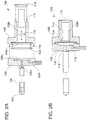
- Figs. 2A and 2B are explanatory drawings showing a detailed structure of the ejecting unit 100.
- Fig. 2A is an exploded view of the ejecting unit 100 in cross section
- Fig. 2B is a cross-sectional view after assembly.
- the rear block 108 is formed with a large circular and shallow depression 108c at a substantially center of a mating surface with respect to the front block 106.
- the depression 108c is formed with a through hole 108h having a circular cross section at a center position thereof so as to penetrate the rear block 108.
- a metallic thin diaphragm 114 so as to close the through hole 108h.
- a peripheral edge portion of the diaphragm 114 is secured to the bottom portion of the depression 108c in an air-tight manner by a method such as brazing or diffusion bonding.
- An annular shaped metallic reinforcing panel 120 is loosely fitted to the depression 108c from above the diaphragm 114.
- the thickness of the reinforcing panel 120 is set to a thickness so that an end surface of the rear block 108 formed with the depression 108c and the end surface of the reinforcing panel 120 are flush with each other when the reinforcing panel 120 is fitted from above the diaphragm 114.
- the through hole 108h closed by the diaphragm 114 accommodates the actuator 112 (the laminated piezoelectric element in this embodiment), and on the rear side of the actuator 112, the through hole 108h is closed by a disk-shaped metallic bottom panel 118.
- a circular metallic shim 116 is accommodated between the actuator 112 and the diaphragm 114. The thickness of the shim 116 is selected so that the diaphragm 114, the shim 116, the actuator 112, and the bottom panel 118 come in contact just with each other when the actuator 112 is accommodated in the through hole 108h of the rear block 108 and closing the through hole 108h with the bottom panel 118.
- the front block 106 is formed with a circular and shallow depression 106c on the mating surface with respect to the rear block 108.
- the inner diameter of the depression 106c is set to be almost the same as the inner diameter of the reinforcing panel 120 fitted to the rear block 108.
- the front block 106 is provided with a supplying channel 106i for supplying liquid to the liquid chamber 110 from the side of the front block 106.
- a small-diameter ejection channel 106o which allows passage of the liquid pressurized in the liquid chamber 110 is penetrated through the depression 106c at the center position thereof.
- An inner diameter portion of the liquid channel tube 104 is fitted on a portion where the ejection channel 106o opens. Then, the ejection nozzle 102 is fitted on a distal end of the liquid channel tube 104.
- the cross-sectional area of the channel of the liquid ejected from the liquid chamber 110 is configured to be increased in the liquid channel tube 104 after the ejection channel 106o, and then is decreased again in a portion of the ejection nozzle 102 at the distal end of the liquid channel tube 104.
- Fig. 2B is a cross-sectional view showing a state in which the ejecting unit 100 is assembled.
- an end surface of the reinforcing panel 120 is flush with an end surface of the rear block 108, and the liquid chamber 110 is defined between the front block 106 and the rear block 108 when mating the front block 106 to this surface.
- the shim 116 and the actuator 112 are accommodated in the through hole 108h of the rear block 108 and the bottom panel 118 is mounted, the diaphragm 114, the shim 116, the actuator 112, and the bottom panel 118 come into just contact with each other.
- Fig. 3 is an explanatory drawing showing a configuration of the control unit 200 that controls the actions of the ejecting unit 100 and the supply pump 300.
- the control unit 200 includes an operating unit 202 configured with an operation panel or the like, an action controller 204 configured with a CPU or the like, a pump drive unit 206 that drives the supply pump 300, a drive voltage generator 208 that generates a drive voltage waveform of the actuator 112 under the control of the action controller 204, a data storage 210 having various data for generating the drive voltage waveform stored therein, a voltage amplifier 212 that amplifies the drive voltage waveform generated by the drive voltage generator 208, and an air-bubble detector 250 that detects air bubbles trapped in the ejecting unit 100 by detecting a drive current flowing in the actuator 112 when the drive voltage waveform is applied to the actuator 112 of the ejecting unit 100.
- the action controller 204 When an operator operates the operating panel of the operating unit 202, a signal is transmitted to the action controller 204, and the action controller 204 outputs a drive command to the pump drive unit 206. Then, the pump drive unit 206 drives the supply pump 300 and, consequently, a supply of liquid into the liquid chamber 110 in the ejecting unit 100 is started. Subsequently, the action controller 204 outputs a drive voltage waveform generation command to the drive voltage generator 208. Then, the drive voltage generator 208 reads out required data from the data storage 210, generates a drive voltage waveform of the actuator 112 built in the ejecting unit 100, and then outputs the generated drive voltage waveform to the voltage amplifier 212. The voltage amplifier 212 amplifies the received voltage value of the drive voltage waveform, and then applies the amplified drive voltage waveform to the actuator 112 of the ejecting unit 100.
- the air-bubble detector 250 receives a signal (timing signal) which indicates a timing of application of the drive voltage waveform to the actuator 112 from the action controller 204 (or the drive voltage generator 208) and detects the drive current flowing in the actuator 112, thereby detecting the air bubbles trapped in the ejecting unit 100, and outputting a signal indicating the result of detection (air-bubble detecting signal) to the action controller 204.
- a signal timing signal
- FIGs. 4A and 4B are explanatory drawings showing an action of the ejecting unit 100 ejecting liquid according to the embodiment.
- Fig. 4A illustrates a state in which the supply pump 300 is driven but the actuator 112 is not driven (a state before application of a driving voltage). In this state, as indicated by a thick broken arrow, the liquid chamber 110 is filled with liquid supplied by the supply pump 300. The drawing indicates that the liquid chamber 110 is filled with the liquid by hatching the liquid chamber 110.
- the actuator 112 is driven by applying the drive voltage. Then, the actuator 112 is deformed in the direction of elongation, thereby making an attempt to deform the diaphragm 114 and reduce the volume of the liquid chamber 110. Consequently, the liquid in the liquid chamber 110 is pressurized, and is injected from the ejection nozzle 102 via the ejection channel and the liquid channel tube 104. The volume of the liquid ejected at this time is almost equal to the volume of the liquid chamber 110 reduced by the deformation of the actuator 112.
- the supplying channel 106i is also connected to the liquid chamber 110. Therefore, the liquid pressurized in the liquid chamber 110 is considered to flow out not only from the ejection channel 106o, but also from the supplying channel 106i. However, actually, the liquid pressurized in the liquid chamber 110 flows out exclusively from the ejection channel 106o, and does not flow out from the supplying channel 106i, The reason will be described below. First of all, since the liquid in the supplying channel 106i attempts to flow into the liquid chamber 110, the flow of the liquid in the supplying channel 106i needs to be pushed backward in order to allow the liquid pressurized in the liquid chamber 110 to flow out from the supplying channel 106i.
- the pressurized liquid since the liquid in the supplying channel 106i is pumped by the supply pump 300, the pressurized liquid must overcome the pressure of the pump as well. In contrast, in the ejection channel 106o, there is no flow of liquid which hinders an outflow from the liquid chamber 110, and the pressure of the supply pump 300 for pumping the liquid does not act in the direction which hinders the outflow from the liquid chamber 110. Therefore, the liquid pressurized in the liquid chamber 110 flows out not from the supplying channel 106i, but exclusively from the ejection channel 106o.
- Fig. 4B illustrates a state in which the drive voltage is applied to the actuator 112, and hence the actuator 112 is deformed to reduce the volume of the liquid chamber 110, whereby the liquid is ejected from the ejection nozzle 102 in a pulsed manner by an amount pushed out from the liquid chamber 110.
- the expression "to eject pulsed liquid” includes a state of intermittent ejection in which ejection and stop of the liquid are repeated as a matter of course.
- the ejection in the state of pulsed flow is included in the expression "to eject pulsed liquid”.
- the pulsed liquid is ejected in this manner, the voltage applied to the actuator 112 is removed. Then, the deformed actuator 112 is restored to the original length and the volume of the liquid chamber 110 reduced correspondingly is restored to the original volume. With this movement, the liquid is supplied from the supply pump 300 to the liquid chamber 110 and, consequently, the actuator 112 shown in Fig. 4A is restored to the state before being driven.
- the actuator 112 is deformed as shown in Fig. 4B , whereby the liquid is ejected from the ejection nozzle 102 in a pulsed manner by an amount pushed out from the liquid chamber 110. In this manner, in the excision device 10 in this embodiment, every time the drive voltage is applied to the actuator 112, the pulsed liquid can be ejected from the ejection nozzle 102.
- the pulsed liquid is ejected using the mechanism as described above, if the air bubbles get into the liquid chamber 110, when the volume of the liquid chamber 110 is reduced by driving the actuator 112, the air bubbles are crushed. Consequently, the liquid cannot be pressurized significantly, so that the flow velocity of the liquid ejected from the ejection nozzle 102 is lowered. Since the amount of liquid to be pushed out from the liquid chamber 110 is reduced by an amount corresponding to the crushed air bubbles, the amount of liquid ejected from the ejection nozzle 102 is also reduced. When a significantly large quantity of air bubbles are trapped in the liquid chamber 110, the flow velocity or the amount of liquid ejected from the ejection nozzle 102 is significantly reduced, and hence the operator can recognize it immediately.
- the flow velocity or the amount of liquid ejected from the ejection nozzle 102 can be restored to the normal state by discharging the air bubbles by operating the supply pump 300 for a while without driving the actuator 112, for example.
- the excision device 10 in this embodiment is configured to detect the air bubbles trapped in the ejecting unit 100 in a manner described below.
- Figs. 5A and 5B are explanatory drawings showing a principle that the excision device 10 in this embodiment detects the air babbles trapped in the ejecting unit 100.
- a current waveform of a drive current flowing in the actuator 112 when a drive voltage waveform is applied to the actuator 112 is shown.
- Fig. 5A shows a current waveform when the air bubbles are not trapped in the ejecting unit 100
- Fig. 5B shows a current waveform when the air bubbles are trapped in the ejecting unit 100.
- the same drive voltage waveform is applied to the actuator 112.
- the drive voltage waveform of this embodiment employs a voltage waveform generated by combining two sinusoidal waveforms.
- part of the waveform where the voltage value rises from voltage 0 to a maximum voltage is configured with a monotonously increasing portion of the sinusoidal waveform (the angular range: part from - ⁇ /2 to ⁇ /2)
- part of the waveform where the voltage value is lowered from the maximum voltage to the voltage 0 is configured with a monotonously decreasing portion of the sinusoidal waveform (the angular range: part from ⁇ /2 to 3 ⁇ /2).
- the drive voltage waveform configured in this manner has a waveform in which the voltage value rises smoothly from the voltage 0 to the maximum voltage and lowers smoothly from the maximum voltage to the voltage 0. Therefore, the actuator 112 can be deformed smoothly.
- the period required for lowering the voltage value from the maximum voltage to the voltage 0 is set to be several times (on the order of five times) longer than the period required for rising the voltage value from the voltage 0 to the maximum voltage.
- the actuator 112 is deformed in the elongating direction when the voltage value to be applied rises (the direction to reduce the volume of the liquid chamber 110), and is deformed in the shortening direction when the voltage value to be applied is lowered (the direction to increase the volume of the liquid chamber 110). Therefore, by applying the drive voltage waveform as described above to the actuator 112, the volume of the liquid chamber 110 can be reduced in a short time, and then restored to the original volume slowly using a period on the order of five times the period of reduction.
- the actuator 112 receives a reaction force from the liquid chamber 110.
- the actuator 112 is configured with the piezoelectric element having an electrostrictive effect such as the piezo element. Therefore, a back electromotive force according to the reaction force is generated in the actuator 112. Consequently, an electric current determined by the drive voltage waveform to be applied and the back electromotive force according to the reaction force from the liquid chamber 110 flows into the actuator 112.
- the reaction forces that the actuator 112 receives are different between a case where the air bubbles are trapped in the liquid chamber 110 and a case where the air bubbles are not trapped in the liquid chamber 110. Therefore, the generated back electromotive forces are also different, and the electric currents flowing into the actuator 112 are also different.
- the current waveforms to be obtained are different between the case where the air bubbles are not trapped in the liquid chamber 110 and the case where the air bubbles are trapped in the liquid chamber 110. Accordingly, determination of the presence or absence of the trapped air bubbles is enabled from the difference in current waveform by detecting the drive current flowing into the actuator 112.
- the excision device 10 in this embodiment detects the air bubbles trapped in the ejecting unit 100 (the liquid chamber 110, the supplying channel 106i, the ejection channel 106o) on the basis of the principle as described above.
- the laminated piezoelectric element is used as the actuator 112.
- the same phenomenon may occur also when a solenoid or the like is used as the actuator 112.
- the volume of the liquid chamber 110 is quickly reduced because the air bubbles are crushed, and a drive shaft provided at a center of the solenoid is quickly moved. Consequently, the velocity of variations in magnetic flux density passing through a coil provided in the periphery of the drive shaft is increased, and an induced electromotive force is generated in the coil, whereby the waveform of the electric current (drive current) flowing in the actuator 112 varies.
- the actuator 112 is configured of members other than the laminated piezoelectric element, the similar phenomenon may occur. Therefore, the presence or absence of the air bubbles trapped in the liquid chamber 110 (or the ejecting unit 100) can be detected by detecting the drive current of the actuator 112.
- the difference in drive current waveform flowing into the actuator 112 may be detected by any method.
- the difference in current waveform can be detected easily by focusing on the following points.
- the peak current value rises when the air bubbles are trapped. Therefore, the difference in drive current waveform can be detected immediately by detecting the peak current value.
- the current value at a timing when the drive voltage waveform is turned from rising to lowering is lowered by the air bubbles trapped therein. Therefore, the difference in drive current waveform can also be detected immediately by detecting the current value at this timing.
- the method of detecting the trapped air bubbles will be described in detail while focusing on the point described above.
- Fig. 6 is an explanatory drawing showing an internal configuration of an air-bubble detector 250 according to a first example.
- the air-bubble detector 250 in the first example includes electric circuits such as a current detector 251, a peak hold unit 252, a comparator 253, a delaying unit 254, and a latch portion 255.
- the current detector 251 is configured mainly with a coil. When an electric current flows toward the actuator 112, an induced electromotive force is generated in the coil, and hence the voltage according to the current value is generated. The voltage generated in this manner is output to the peak hold unit 252.
- the peak hold unit 252 is configured mainly with an IC chip, and has a function to hold the maximum value from the voltage values input thereto.
- the peak hold unit 252 is configured to receive an input of a timing signal from the action controller 204 (or the drive voltage generator 208), and reset the held voltage value upon receipt of the timing signal.
- An output from the peak hold unit 252 (the held maximum voltage) is input to the comparator 253.
- the comparator 253 is also configured mainly with an IC chip, and has a function to compare the input voltage with a preset threshold voltage and, according to the result of comparison, output a voltage state of either "Hi” or "Low". In this example, when the voltage input from the peak hold unit 252 is larger than the threshold voltage, the voltage state of "Hi” is output, while when input voltage is smaller than the threshold voltage, the voltage state of "Low” is output.
- the latch portion 255 is also configured mainly with an IC chip, and has a function to output the voltage value input upon receipt of a latch signal and update the output voltage every time when receiving the latch signal.
- the latch signal is generated by delaying the above-described timing signal by the delaying unit 254. If the latch portion 255 had already received the voltage of "Hi” state from the comparator 253 when receiving the latch signal, the voltage in "Hi” state is output to the action controller 204 as the air-bubble detecting signal. If the latch portion 255 had already received the voltage of "Low” state from the comparator 253 when receiving the latch signal, the voltage in "Low” state is output to the action controller 204 as the air-bubble detecting signal.
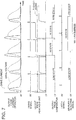
- Fig. 7 is an explanatory drawing showing a state in which the air-bubble detector 250 in the first example detects air bubbles.
- the drive voltage waveform to be applied to the actuator 112, and a drive current waveform flowing in the actuator 112 thereby are shown.
- the drive voltage waveform is applied five times continuously to the actuator 112, and the drive current waveforms flowing the five times into the actuator 112 every time when the drive voltage waveform is applied are shown.
- first two and the last waveforms are drive current waveforms which appear when the air bubbles are not trapped in the liquid chamber 110 (see Fig. 5A )
- the third and fourth waveforms are the drive current waveforms which appear when the air bubbles are trapped (see Fig. 5B ).
- the timing signal output from the action controller 204 (or the drive voltage generator 208) is shown.
- the timing signal is output at timings when the application of the drive voltage waveform to the actuator 112 is started.
- An output waveform from the peak hold unit 252 is shown underside of the timing signal.
- the output from the peak hold unit 252 is reset to a voltage 0 when the timing signal is input, and then rises with the output voltage from the current detector 251 rising. However, even when the output voltage from the current detector 251 is turned to be lowered, the output voltage from the peak hold unit 252 is not lowered, and the maximum output voltage is maintained. When the timing signal is input, the voltage is reset to zero again.
- the output waveform from the peak hold unit 252 indicates a state in which the peak value of the drive current flowing in the actuator 112 varies every time when the drive voltage waveform is applied.
- the output voltage from the peak hold unit 252 is low when the actuator 112 is driven for the first and second times and the last time, and the output voltage from the peak hold unit 252 is high when the actuator 112 is driven for the third time and the fourth time.
- the magnitude relationships between the output waveforms from the peak hold unit 252 obtained in this manner and the preset threshold voltage are detected using the comparator 253.
- the threshold voltage for comparing with the output waveforms from the peak hold unit 252 is indicated by an alternate long and short dash line.
- the output waveform from the comparator 253 is shown on the underside of the output waveform from the peak hold unit 252. As illustrated, when the output voltage from the peak hold unit 252 is lower than the threshold voltage, the output from the comparator 253 is brought into "Low” state. In contrast, when the output voltage from the peak hold unit 252 is higher than the threshold voltage, the output from the comparator 253 is brought into "Hi" state. In the example shown in Fig.
- the output from the comparator 253 is brought into "Low” state when the actuator 112 is driven for the first and second times and the last time, and the output from the comparator 253 is brought into "Hi” state when the actuator 112 is driven for the third time and the fourth time.
- the latch portion 255 Every time when the latch portion 255 receives the output from the comparator 253 and receives an input of the latch signal, the latch portion 255 outputs the voltage state (either one of "Low state and "Hi” state) being output from the comparator 253 at that timing as an air bubble detecting signal.
- the latch signal is illustrated underside of the output waveform from the comparator 253, and the air bubble detecting signal output from the latch portion 255 is illustrated under side of the latch signal. Consequently, the air bubble detecting signal is brought into "Hi” state from the third time driving to the fourth time driving from among the five times driving of the actuator 112, so that the fact that the air bubbles are trapped in the liquid chamber 110 is detected.
- the presence or absence of the air bubbles trapped in the liquid chamber 110 (or in the ejecting unit 100) can be quickly and reliably, and very easily detected by detecting the peak value of the drive current when the actuator 112 is driven. Consequently, such event that the operator of the excision device 10 continues to use the excision device 10 without recognizing the fact that the air bubbles are trapped in the ejecting unit 100 or the fact that the incising capability or the excising capability is lowered can be avoided.
- the air bubbles trapped in the ejecting unit 100 are detected on the basis of the peak value of the drive current when the actuator 112 is driven.
- the variations of the drive current waveform caused by the presence or absence of the trapped air bubbles appear not only in the peak current value, but also the presence or absence of the trapped air bubbles can be detected by detecting the variations in drive current waveform while focusing on a different point.
- the current value at a timing when the drive voltage waveform applied to the actuator 112 is turned from rising to lowering.
- Fig. 8 is an explanatory drawing showing an internal configuration of the air-bubble detector 250 according to the second example.
- the air-bubble detector 250 in the second example includes electric circuits such as the current detector 251, a sample hold unit 256, and the comparator 253. From among these members, the current detector 251 is the same as that used in the first example. When an electric current flows toward the actuator 112, the current detector 251 generates a voltage according to the current value and outputs the generated voltage to the sample hold unit 256.
- the sample hold unit 256 is also configured mainly with an IC chip, and has a function to hold a voltage being input at the time point of reception of the timing signal until reception of a next timing signal.
- the timing signal is output from the action controller 204 (or the drive voltage generator 208).
- the comparator 253 is also the same as that used in the first example, and has a function to compare the input voltage with the preset threshold voltage and, according to the result of comparison, output the voltage state of either "Hi" or "Low".
- the comparator 253 when the voltage input from the sample hold unit 256 is smaller than the threshold voltage, the voltage state of "Low” is output, while when the input voltage is larger than the threshold voltage, the voltage state of "Hi” is output.
- the output from the comparator 253 obtained in this manner is used as the air-bubble detecting signal.
- Fig. 9 is an explanatory drawing showing a state in which the air-bubble detector 250 in the second example detects air bubbles.
- the drive voltage waveform to be applied to the actuator 112 and the drive current waveform flowing in the actuator 112 thereby are shown also in an uppermost level in Fig. 9 .
- first two and the last waveforms from among the five drive voltage waveforms are waveforms which appear when the air bubbles are not trapped, and the third and fourth waveforms are waveforms which appear when the air bubbles are trapped.
- the timing signal output from the action controller 204 (or the drive voltage generator 208) is shown.
- a timing signal is output at the timings when the drive voltage waveform to be applied to the actuator 112 is turned from rising to lowering.
- an output waveform from the sample hold unit 256 is shown.
- the sample hold unit 256 has a function to output a voltage input from the current detector 251 when receiving the timing signal. Therefore, as shown in Fig. 9 , the voltage that the sample hold unit 256 outputs rises for the first two drive current waveforms and the last drive current waveform, and the voltage output from the sample hold unit 256 is lowered for the third and fourth drive current waveforms.
- the magnitude relationships between the outputs from the sample hold unit 256 obtained in this manner and the preset threshold voltage are detected using the comparator 253.
- the threshold voltage is shown by an alternate long and short dash line.
- an output from the comparator 253 is brought into "Low” state for the first two drive current waveforms and the last drive current waveform which correspond to the case where the air bubbles are not trapped.
- the output from the comparator 253 is brought into "Hi" state for the third and fourth drive current waveforms which correspond to the case where the air bubbles are trapped. Therefore, also by using the output from the comparator 253 as the air-bubble detecting signal, the trapping of the air bubbles can be detected quickly and easily.
- the threshold voltage used for detecting the air bubbles in the air-bubble detector 250 is fixed.
- the drive current waveforms flowing in the actuator 112 when the air bubbles are trapped are different from one actuator 112 to another. Therefore, the optimal values of the threshold voltage used for detecting the air bubbles are different from one actuator 112 to another. Therefore, the value of the threshold voltage may be varied depending on the individual difference of the actuator 112.
- Fig. 10 is an explanatory drawing showing a configuration of the control unit 200 according to a modification.
- the control unit 200 in the modification is different from the control units 200 in the first example and the second example described above in conjunction with Fig. 3 in that the action controller 204 obtains the individual difference information of the actuator 112 from the ejecting unit 100 and in that the action controller 204 sets the threshold voltage of the air-bubble detector 250.
- the individual difference information of the actuator 112 here means data relating to the current value at the timing when the peak current value or the drive voltage turns from rising to lowering obtained by actually measuring the drive current waveform when the air bubbles get into the ejecting unit 100.
- An IC chip having the individual difference information of the actuator 112 stored therein is mounted on the ejecting unit 100, and the action controller 204 of the control unit 200 is capable of reading out data stored in the IC chip and obtaining the individual difference information of the actuator 112.
- the individual difference information of the actuator 112 may be a current value at a timing when the peak current values or the drive voltage is turned from rising to lowering or may be a correcting value determined on the basis of the current value. Alternatively, it may be the number which indicates the types that the actuators 112 are classified into several types on the basis of the measured current values.
- the action controller 204 upon receipt of the signal from the operating unit 202, the action controller 204 outputs a drive command to the pump drive unit 206 and drives the supply pump 300, and also outputs a drive voltage waveform generation command to the drive voltage generator 208 to start driving the actuator 112 integrated in the ejecting unit 100.
- the description will be omitted here.
- the actions for detecting the air bubbles are slightly different from the above-described first embodiment and the second embodiment.
- the action controller 204 obtains the individual difference information of the actuator 112 from the ejecting unit 100. After having determined the threshold voltage according to the obtained individual difference information, the result is output to the air-bubble detector 250.
- the action controller 204 may set the threshold voltage for the air-bubble detector 250 by outputting the value of the threshold voltage or by storing a standard threshold voltage in the air-bubble detector 250 and outputting the correcting value of the threshold value. Alternatively, storing a plurality of threshold voltages in the air-bubble detector 250 and specifying one of the stored threshold voltages are also applicable.
- the air-bubble detector 250 in the modification detects the presence or absence of the air bubbles by comparing the threshold voltage set in this manner and the output from the peak hold unit 252 or the output from the sample hold unit 256.
- the presence and absence of the air bubbles can be detected using an adequate threshold voltage considering the individual difference of the actuator 112. Therefore, even when a small quantity of air bubbles are trapped, quick and accurate detection of the trapping of the air bubbles are achieved without being affected by the individual difference of the actuator 112.
- the threshold voltage is varied according to the individual difference of the actuator 112.
- the threshold voltage may be varied according to the drive voltage waveform applied to the actuator 112.
Landscapes
- Health & Medical Sciences (AREA)
- Life Sciences & Earth Sciences (AREA)
- Surgery (AREA)
- Molecular Biology (AREA)
- Engineering & Computer Science (AREA)
- Biomedical Technology (AREA)
- Heart & Thoracic Surgery (AREA)
- Medical Informatics (AREA)
- Nuclear Medicine, Radiotherapy & Molecular Imaging (AREA)
- Animal Behavior & Ethology (AREA)
- General Health & Medical Sciences (AREA)
- Public Health (AREA)
- Veterinary Medicine (AREA)
- Surgical Instruments (AREA)
- Ink Jet (AREA)
- Reciprocating Pumps (AREA)
Claims (6)
- Exzisionsvorrichtung (10), die zum Exzidieren von lebendem Gewebe ausgelegt ist, indem Flüssigkeit in Richtung des lebenden Gewebes ausgestoßen wird, umfassend:a) eine Flüssigkeitszufuhreinheit (300, 302, 304), die zum Zuführen der auszustoßenden Flüssigkeit ausgelegt ist;b) eine Flüssigkeitskammer (110), die ausgelegt ist, um mit der zugeführten Flüssigkeit gefüllt zu werden;c) eine Ausstoßdüse (102), die mit der Flüssigkeitskammer verbunden ist;d) ein Antriebselement (112), das ausgelegt ist, um in die Richtung verformt zu werden, um das Volumen der Flüssigkeitskammer zu reduzieren, wenn eine Antriebsspannung angelegt wird, und zwar mehr als in einem Fall, wenn die Antriebsspannung nicht angelegt wird;e) eine Flüssigkeitsausstoßeinheit (104), die ausgelegt ist, um die Flüssigkeit in der Flüssigkeitskammer in pulsierender Weise aus der Ausstoßdüse auszustoßen, indem die Antriebsspannung an das Antriebselement in einem Zustand angelegt wird, in dem die Flüssigkeitskammer mit der zugeführten Flüssigkeit gefüllt ist; unddadurch gekennzeichnet, dass die Exzisionsvorrichtung umfasst:f) eine Luftblasenerkennungseinheit (250), die ausgelegt ist, um Luftblasen in der Flüssigkeitskammer zu erkennen, indem ein elektrischer Strom gemessen wird, der in dem Antriebselement (112) fließt, wenn die Antriebsspannung an das Antriebselement angelegt wird.
- Exzisionsvorrichtung nach Anspruch 1, wobei die Luftblasenerkennungseinheit (250) eine Einheit ist, die zum Erkennen der Luftblasen in der Flüssigkeitskammer (110) adaptiert ist, indem ein Spitzenstrom des elektrischen Stroms erkannt wird, der in dem Antriebselement (112) fließt.
- Exzisionsvorrichtung nach Anspruch 1, wobei
die Flüssigkeitsausstoßeinheit (104) eine Einheit ist, die eine Spannung mit einer Wellenform, die zu einer vorbestimmten Maximalspannung steigt und dann von der Maximalspannung absinkt, an das Antriebselement anlegt, und
die Luftblasenerkennungseinheit (250) eine Einheit ist, die die Luftblasen in der Flüssigkeitskammer erkennt, indem ein elektrischer Strom erkannt wird, der in dem Antriebselement fließt, wenn die Maximalspannung an das Antriebselement angelegt wird. - Exzisionsvorrichtung nach Anspruch 3, wobei die Luftblasenerkennungseinheit (250) eine Einheit ist, die die Luftblasen in der Flüssigkeitskammer (110) erkennt, indem der elektrische Strom erkannt wird, der in dem Antriebselement (112) fließt, wobei dieser, wenn die Maximalspannung an das Antriebselement (112) angelegt wird und wenn die Luftblase in der Flüssigkeitskammer (110) gefangen ist, niedriger ist als der elektrische Strom, der in dem Antriebselement (112) fließt, wenn die Maximalspannung an das Antriebselement (112) angelegt wird und wenn die Luftblase nicht in der Flüssigkeitskammer (110) gefangen ist.
- Exzisionsvorrichtung nach einem der Ansprüche 1 bis 4, ferner umfassend:eine Speichereinheit (210), die einen Referenzstrom gemäß dem Antriebselement speichert, wobeidie Luftblasenerkennungseinheit eine Einheit ist, die die Luftblasen in der Flüssigkeitskammer erkennt, indem der elektrische Strom, der in dem Antriebselement fließt, mit dem Referenzstrom verglichen wird, der gemäß dem Antriebselement gespeichert ist.
- Luftblasenerkennungsverfahren, das auf eine Exzisionsvorrichtung (10) angewendet wird, einschließend eine Flüssigkeitskammer (110), die ausgelegt ist, um mit Flüssigkeit gefüllt zu werden, die in Richtung von lebendem Gewebe ausgestoßen werden soll; eine Ausstoßdüse (102), die mit der Flüssigkeitskammer verbunden ist; ein Antriebselement (112), das ausgelegt ist, um, wenn eine Antriebsspannung angelegt wird, mehr als in einem Fall, in dem die Antriebsspannung nicht angelegt wird, in der Richtung verformt zu werden, um das Volumen der Flüssigkeitskammer zu reduzieren; und eine Luftblasenerkennungseinheit, die ausgelegt ist, um einen elektrischen Strom zu erkennen, der in dem Vorrichtungselement zum Erkennen von Luftblasen in der Flüssigkeitskammer fließt, wobei das Verfahren umfasst:a) Zuführen der Flüssigkeit in das Innere der Flüssigkeitskammer;b) Ausstoßen der Flüssigkeit in der Flüssigkeitskammer aus der Ausstoßdüse, indem die Antriebsspannung an das Antriebselement in einem Zustand angelegt wird, indem die Flüssigkeitskammer mit der Flüssigkeit gefüllt ist; undc) Erkennen von Luftblasen in der Flüssigkeitskammer durch Messen eines elektrischen Stroms, der in dem Antriebselement fließt, wenn die Antriebsspannung an das Antriebselement angelegt wird.
Applications Claiming Priority (1)
| Application Number | Priority Date | Filing Date | Title |
|---|---|---|---|
| JP2010043861A JP2011177330A (ja) | 2010-03-01 | 2010-03-01 | 切除装置、および気泡検出方法 |
Publications (3)
| Publication Number | Publication Date |
|---|---|
| EP2363084A2 EP2363084A2 (de) | 2011-09-07 |
| EP2363084A3 EP2363084A3 (de) | 2015-07-08 |
| EP2363084B1 true EP2363084B1 (de) | 2017-05-03 |
Family
ID=44148794
Family Applications (1)
| Application Number | Title | Priority Date | Filing Date |
|---|---|---|---|
| EP11155967.0A Not-in-force EP2363084B1 (de) | 2010-03-01 | 2011-02-25 | Exzisionsvorrichtung und Luftblasenerkennungsvorrichtung |
Country Status (4)
| Country | Link |
|---|---|
| US (2) | US20110213396A1 (de) |
| EP (1) | EP2363084B1 (de) |
| JP (1) | JP2011177330A (de) |
| CN (1) | CN102188274B (de) |
Families Citing this family (9)
| Publication number | Priority date | Publication date | Assignee | Title |
|---|---|---|---|---|
| US8794931B2 (en) | 2010-12-24 | 2014-08-05 | Seiko Epson Corporation | Fluid ejection device and medical device |
| JP5776447B2 (ja) | 2011-08-30 | 2015-09-09 | セイコーエプソン株式会社 | 噴射した流体によって生体組織を切除するための流体噴射装置に接続して用いられる制御装置および切除装置 |
| US9243619B2 (en) | 2011-09-13 | 2016-01-26 | Seiko Epson Corporation | Liquid feed pump and circulation pump with detection units to detect operating states of the pumps |
| US20140109650A1 (en) * | 2012-10-22 | 2014-04-24 | Seiko Epson Corporation | Dissolved gas content measurement apparatus and liquid treatment apparatus |
| JP2015054015A (ja) * | 2013-09-11 | 2015-03-23 | セイコーエプソン株式会社 | 医療機器 |
| JP2016120066A (ja) | 2014-12-25 | 2016-07-07 | セイコーエプソン株式会社 | 液体噴射制御装置、液体噴射システム及び制御方法 |
| JP2016120067A (ja) * | 2014-12-25 | 2016-07-07 | セイコーエプソン株式会社 | 液体噴射制御装置、液体噴射システム及び制御方法 |
| JP7449838B2 (ja) * | 2020-10-14 | 2024-03-14 | 株式会社日立製作所 | 行動解析システム及びそれを用いた行動解析方法 |
| US11841336B2 (en) * | 2021-01-15 | 2023-12-12 | Te Connectivity Solutions Gmbh | Bubble detection sensor |
Family Cites Families (19)
| Publication number | Priority date | Publication date | Assignee | Title |
|---|---|---|---|---|
| US4518974A (en) * | 1982-09-21 | 1985-05-21 | Ricoh Company, Ltd. | Ink jet air removal system |
| JPS6080944U (ja) * | 1983-11-10 | 1985-06-05 | キヤノン株式会社 | 記録ヘツドのモニタ装置 |
| JP2812593B2 (ja) | 1991-11-11 | 1998-10-22 | アルプス電気株式会社 | インクジェット記録ヘッドの気泡検出装置 |
| US5500657A (en) * | 1991-11-11 | 1996-03-19 | Alps Electric Co., Ltd. | Air-bubble detection apparatus of ink jet recording head, and method and apparatus for restoring ink jet recording head |
| JP3213431B2 (ja) | 1993-04-12 | 2001-10-02 | キヤノン株式会社 | インクジェット記録装置およびインク残量検出方法 |
| JPH1199646A (ja) | 1997-09-29 | 1999-04-13 | Fuji Electric Co Ltd | インクジェット記録ヘッド及びインクジェット記録装置 |
| JPH11334102A (ja) * | 1998-05-25 | 1999-12-07 | Mitsubishi Electric Corp | インクジェット式プリンタ、気泡検出回路及び気泡検出方法 |
| US6375299B1 (en) * | 1998-11-02 | 2002-04-23 | Encad, Inc. | Faulty ink ejector detection in an ink jet printer |
| JP3740673B2 (ja) * | 1999-11-10 | 2006-02-01 | 株式会社日立製作所 | ダイヤフラムポンプ |
| JP2003118093A (ja) | 2001-10-12 | 2003-04-23 | Seiko Epson Corp | インクジェットヘッドの駆動制御装置およびインク吐出不良検出方法 |
| JP3697209B2 (ja) * | 2001-12-27 | 2005-09-21 | キヤノン株式会社 | 液体吐出検出方法及びその装置とインクジェット記録装置 |
| JP2004009501A (ja) | 2002-06-06 | 2004-01-15 | Hitachi Printing Solutions Ltd | インクジェットプリンタ |
| JP4099822B2 (ja) * | 2002-07-26 | 2008-06-11 | セイコーエプソン株式会社 | ディスペンシング装置、ディスペンシング方法及び生体試料含有溶液吐出不良検出方法 |
| JP4266788B2 (ja) * | 2003-11-21 | 2009-05-20 | セイコーエプソン株式会社 | 流体噴射装置 |
| JP2006231882A (ja) | 2005-02-28 | 2006-09-07 | Fuji Xerox Co Ltd | 画像形成装置及び液体吐出状態判定方法 |
| JP2007090654A (ja) | 2005-09-28 | 2007-04-12 | Fujifilm Corp | 液体吐出装置及び気泡判断方法 |
| JP2007130853A (ja) * | 2005-11-09 | 2007-05-31 | Fujifilm Corp | 液体吐出装置および吐出異常原因抽出方法 |
| JP5082049B2 (ja) * | 2006-09-26 | 2012-11-28 | セイコーエプソン株式会社 | 流体噴射装置および手術具 |
| JP5272363B2 (ja) * | 2007-09-21 | 2013-08-28 | セイコーエプソン株式会社 | 流体噴射装置 |
-
2010
- 2010-03-01 JP JP2010043861A patent/JP2011177330A/ja active Pending
-
2011
- 2011-02-25 EP EP11155967.0A patent/EP2363084B1/de not_active Not-in-force
- 2011-02-25 US US13/035,156 patent/US20110213396A1/en not_active Abandoned
- 2011-03-01 CN CN201110049592.2A patent/CN102188274B/zh not_active Expired - Fee Related
-
2014
- 2014-09-09 US US14/481,752 patent/US9375231B2/en not_active Expired - Fee Related
Non-Patent Citations (1)
| Title |
|---|
| None * |
Also Published As
| Publication number | Publication date |
|---|---|
| EP2363084A2 (de) | 2011-09-07 |
| CN102188274B (zh) | 2015-09-02 |
| EP2363084A3 (de) | 2015-07-08 |
| CN102188274A (zh) | 2011-09-21 |
| US20140379013A1 (en) | 2014-12-25 |
| JP2011177330A (ja) | 2011-09-15 |
| US20110213396A1 (en) | 2011-09-01 |
| US9375231B2 (en) | 2016-06-28 |
Similar Documents
| Publication | Publication Date | Title |
|---|---|---|
| US9375231B2 (en) | Excision device and air-bubble detecting method | |
| US8506584B2 (en) | Fluid jet device, drive device of fluid jet device, surgical instrument, and method of driving fluid jet device | |
| US9528511B2 (en) | Liquid injection device | |
| US9005226B2 (en) | Fluid ejection device and method to control fluid ejection device | |
| EP2476383B1 (de) | Flüssigkeitsausstoßvorrichtung | |
| EP2286745B1 (de) | Flüssigkeitsausgabevorrichtung | |
| CN102397093A (zh) | 液体喷射装置以及使用液体喷射装置的医疗设备 | |
| EP3112160B1 (de) | Flüssigkeitsstrahlvorrichtung | |
| EP2783644A1 (de) | Flüssigkeitsausstossvorrichtung und medizinisches Instrument | |
| US8794931B2 (en) | Fluid ejection device and medical device | |
| CN104970847A (zh) | 流体喷射装置 | |
| CN104972747A (zh) | 流体喷射装置以及流体喷射方法 | |
| JP2006051708A (ja) | 液体吐出装置及び駆動電圧補正方法 | |
| US20150289897A1 (en) | Fluid ejection device | |
| WO2018070264A1 (ja) | 液体吐出装置と液体吐出装置を有する検査装置、液体吐出装置を有する細胞培養装置 | |
| EP1518679B1 (de) | Tröpfchenausstossverfahren und -vorrichtung | |
| JP2009096025A (ja) | 液体噴射装置の回復方法及び液体噴射装置 | |
| JP5636809B2 (ja) | 液体噴射装置 | |
| JP5867545B2 (ja) | 液体噴射装置用制御ユニット | |
| EP1671799B1 (de) | Vorrichtung zur Erkennung von Druckkopffehlern und zugehöriges Verfahren | |
| JP5874307B2 (ja) | 制御装置、液体噴射装置及びプログラム | |
| JP5776246B2 (ja) | 液体噴射装置 | |
| JP2005265689A (ja) | 液体吐出ヘッド及び液体吐出ヘッドの駆動方法並びに液体分注装置 | |
| JP2008036502A (ja) | 微細気泡の生成方法及び微細気泡生成装置 | |
| JP2014184315A (ja) | 液体噴射装置用噴射ユニットのブロック、液体噴射装置用噴射ユニットおよび手術機器 |
Legal Events
| Date | Code | Title | Description |
|---|---|---|---|
| PUAI | Public reference made under article 153(3) epc to a published international application that has entered the european phase |
Free format text: ORIGINAL CODE: 0009012 |
|
| AK | Designated contracting states |
Kind code of ref document: A2 Designated state(s): AL AT BE BG CH CY CZ DE DK EE ES FI FR GB GR HR HU IE IS IT LI LT LU LV MC MK MT NL NO PL PT RO RS SE SI SK SM TR |
|
| AX | Request for extension of the european patent |
Extension state: BA ME |
|
| PUAL | Search report despatched |
Free format text: ORIGINAL CODE: 0009013 |
|
| AK | Designated contracting states |
Kind code of ref document: A3 Designated state(s): AL AT BE BG CH CY CZ DE DK EE ES FI FR GB GR HR HU IE IS IT LI LT LU LV MC MK MT NL NO PL PT RO RS SE SI SK SM TR |
|
| AX | Request for extension of the european patent |
Extension state: BA ME |
|
| RIC1 | Information provided on ipc code assigned before grant |
Ipc: A61B 17/3203 20060101AFI20150603BHEP |
|
| 17P | Request for examination filed |
Effective date: 20151208 |
|
| RBV | Designated contracting states (corrected) |
Designated state(s): AL AT BE BG CH CY CZ DE DK EE ES FI FR GB GR HR HU IE IS IT LI LT LU LV MC MK MT NL NO PL PT RO RS SE SI SK SM TR |
|
| GRAP | Despatch of communication of intention to grant a patent |
Free format text: ORIGINAL CODE: EPIDOSNIGR1 |
|
| INTG | Intention to grant announced |
Effective date: 20160831 |
|
| GRAS | Grant fee paid |
Free format text: ORIGINAL CODE: EPIDOSNIGR3 |
|
| GRAJ | Information related to disapproval of communication of intention to grant by the applicant or resumption of examination proceedings by the epo deleted |
Free format text: ORIGINAL CODE: EPIDOSDIGR1 |
|
| GRAL | Information related to payment of fee for publishing/printing deleted |
Free format text: ORIGINAL CODE: EPIDOSDIGR3 |
|
| GRAP | Despatch of communication of intention to grant a patent |
Free format text: ORIGINAL CODE: EPIDOSNIGR1 |
|
| INTC | Intention to grant announced (deleted) | ||
| INTG | Intention to grant announced |
Effective date: 20170203 |
|
| GRAA | (expected) grant |
Free format text: ORIGINAL CODE: 0009210 |
|
| AK | Designated contracting states |
Kind code of ref document: B1 Designated state(s): AL AT BE BG CH CY CZ DE DK EE ES FI FR GB GR HR HU IE IS IT LI LT LU LV MC MK MT NL NO PL PT RO RS SE SI SK SM TR |
|
| REG | Reference to a national code |
Ref country code: GB Ref legal event code: FG4D |
|
| REG | Reference to a national code |
Ref country code: AT Ref legal event code: REF Ref document number: 889080 Country of ref document: AT Kind code of ref document: T Effective date: 20170515 Ref country code: CH Ref legal event code: EP |
|
| REG | Reference to a national code |
Ref country code: IE Ref legal event code: FG4D |
|
| REG | Reference to a national code |
Ref country code: DE Ref legal event code: R096 Ref document number: 602011037478 Country of ref document: DE |
|
| REG | Reference to a national code |
Ref country code: NL Ref legal event code: MP Effective date: 20170503 |
|
| REG | Reference to a national code |
Ref country code: AT Ref legal event code: MK05 Ref document number: 889080 Country of ref document: AT Kind code of ref document: T Effective date: 20170503 |
|
| REG | Reference to a national code |
Ref country code: LT Ref legal event code: MG4D |
|
| PG25 | Lapsed in a contracting state [announced via postgrant information from national office to epo] |
Ref country code: GR Free format text: LAPSE BECAUSE OF FAILURE TO SUBMIT A TRANSLATION OF THE DESCRIPTION OR TO PAY THE FEE WITHIN THE PRESCRIBED TIME-LIMIT Effective date: 20170804 Ref country code: FI Free format text: LAPSE BECAUSE OF FAILURE TO SUBMIT A TRANSLATION OF THE DESCRIPTION OR TO PAY THE FEE WITHIN THE PRESCRIBED TIME-LIMIT Effective date: 20170503 Ref country code: AT Free format text: LAPSE BECAUSE OF FAILURE TO SUBMIT A TRANSLATION OF THE DESCRIPTION OR TO PAY THE FEE WITHIN THE PRESCRIBED TIME-LIMIT Effective date: 20170503 Ref country code: LT Free format text: LAPSE BECAUSE OF FAILURE TO SUBMIT A TRANSLATION OF THE DESCRIPTION OR TO PAY THE FEE WITHIN THE PRESCRIBED TIME-LIMIT Effective date: 20170503 Ref country code: HR Free format text: LAPSE BECAUSE OF FAILURE TO SUBMIT A TRANSLATION OF THE DESCRIPTION OR TO PAY THE FEE WITHIN THE PRESCRIBED TIME-LIMIT Effective date: 20170503 Ref country code: ES Free format text: LAPSE BECAUSE OF FAILURE TO SUBMIT A TRANSLATION OF THE DESCRIPTION OR TO PAY THE FEE WITHIN THE PRESCRIBED TIME-LIMIT Effective date: 20170503 Ref country code: NO Free format text: LAPSE BECAUSE OF FAILURE TO SUBMIT A TRANSLATION OF THE DESCRIPTION OR TO PAY THE FEE WITHIN THE PRESCRIBED TIME-LIMIT Effective date: 20170803 |
|
| PG25 | Lapsed in a contracting state [announced via postgrant information from national office to epo] |
Ref country code: IS Free format text: LAPSE BECAUSE OF FAILURE TO SUBMIT A TRANSLATION OF THE DESCRIPTION OR TO PAY THE FEE WITHIN THE PRESCRIBED TIME-LIMIT Effective date: 20170903 Ref country code: RS Free format text: LAPSE BECAUSE OF FAILURE TO SUBMIT A TRANSLATION OF THE DESCRIPTION OR TO PAY THE FEE WITHIN THE PRESCRIBED TIME-LIMIT Effective date: 20170503 Ref country code: LV Free format text: LAPSE BECAUSE OF FAILURE TO SUBMIT A TRANSLATION OF THE DESCRIPTION OR TO PAY THE FEE WITHIN THE PRESCRIBED TIME-LIMIT Effective date: 20170503 Ref country code: BG Free format text: LAPSE BECAUSE OF FAILURE TO SUBMIT A TRANSLATION OF THE DESCRIPTION OR TO PAY THE FEE WITHIN THE PRESCRIBED TIME-LIMIT Effective date: 20170803 Ref country code: PL Free format text: LAPSE BECAUSE OF FAILURE TO SUBMIT A TRANSLATION OF THE DESCRIPTION OR TO PAY THE FEE WITHIN THE PRESCRIBED TIME-LIMIT Effective date: 20170503 Ref country code: NL Free format text: LAPSE BECAUSE OF FAILURE TO SUBMIT A TRANSLATION OF THE DESCRIPTION OR TO PAY THE FEE WITHIN THE PRESCRIBED TIME-LIMIT Effective date: 20170503 Ref country code: SE Free format text: LAPSE BECAUSE OF FAILURE TO SUBMIT A TRANSLATION OF THE DESCRIPTION OR TO PAY THE FEE WITHIN THE PRESCRIBED TIME-LIMIT Effective date: 20170503 |
|
| PG25 | Lapsed in a contracting state [announced via postgrant information from national office to epo] |
Ref country code: SK Free format text: LAPSE BECAUSE OF FAILURE TO SUBMIT A TRANSLATION OF THE DESCRIPTION OR TO PAY THE FEE WITHIN THE PRESCRIBED TIME-LIMIT Effective date: 20170503 Ref country code: CZ Free format text: LAPSE BECAUSE OF FAILURE TO SUBMIT A TRANSLATION OF THE DESCRIPTION OR TO PAY THE FEE WITHIN THE PRESCRIBED TIME-LIMIT Effective date: 20170503 Ref country code: DK Free format text: LAPSE BECAUSE OF FAILURE TO SUBMIT A TRANSLATION OF THE DESCRIPTION OR TO PAY THE FEE WITHIN THE PRESCRIBED TIME-LIMIT Effective date: 20170503 Ref country code: EE Free format text: LAPSE BECAUSE OF FAILURE TO SUBMIT A TRANSLATION OF THE DESCRIPTION OR TO PAY THE FEE WITHIN THE PRESCRIBED TIME-LIMIT Effective date: 20170503 Ref country code: RO Free format text: LAPSE BECAUSE OF FAILURE TO SUBMIT A TRANSLATION OF THE DESCRIPTION OR TO PAY THE FEE WITHIN THE PRESCRIBED TIME-LIMIT Effective date: 20170503 |
|
| REG | Reference to a national code |
Ref country code: DE Ref legal event code: R097 Ref document number: 602011037478 Country of ref document: DE |
|
| REG | Reference to a national code |
Ref country code: FR Ref legal event code: PLFP Year of fee payment: 8 |
|
| PG25 | Lapsed in a contracting state [announced via postgrant information from national office to epo] |
Ref country code: IT Free format text: LAPSE BECAUSE OF FAILURE TO SUBMIT A TRANSLATION OF THE DESCRIPTION OR TO PAY THE FEE WITHIN THE PRESCRIBED TIME-LIMIT Effective date: 20170503 Ref country code: SM Free format text: LAPSE BECAUSE OF FAILURE TO SUBMIT A TRANSLATION OF THE DESCRIPTION OR TO PAY THE FEE WITHIN THE PRESCRIBED TIME-LIMIT Effective date: 20170503 |
|
| PLBE | No opposition filed within time limit |
Free format text: ORIGINAL CODE: 0009261 |
|
| STAA | Information on the status of an ep patent application or granted ep patent |
Free format text: STATUS: NO OPPOSITION FILED WITHIN TIME LIMIT |
|
| 26N | No opposition filed |
Effective date: 20180206 |
|
| PG25 | Lapsed in a contracting state [announced via postgrant information from national office to epo] |
Ref country code: SI Free format text: LAPSE BECAUSE OF FAILURE TO SUBMIT A TRANSLATION OF THE DESCRIPTION OR TO PAY THE FEE WITHIN THE PRESCRIBED TIME-LIMIT Effective date: 20170503 |
|
| REG | Reference to a national code |
Ref country code: CH Ref legal event code: PL |
|
| PG25 | Lapsed in a contracting state [announced via postgrant information from national office to epo] |
Ref country code: MC Free format text: LAPSE BECAUSE OF FAILURE TO SUBMIT A TRANSLATION OF THE DESCRIPTION OR TO PAY THE FEE WITHIN THE PRESCRIBED TIME-LIMIT Effective date: 20170503 |
|
| REG | Reference to a national code |
Ref country code: IE Ref legal event code: MM4A |
|
| REG | Reference to a national code |
Ref country code: BE Ref legal event code: MM Effective date: 20180228 |
|
| PG25 | Lapsed in a contracting state [announced via postgrant information from national office to epo] |
Ref country code: CH Free format text: LAPSE BECAUSE OF NON-PAYMENT OF DUE FEES Effective date: 20180228 Ref country code: LU Free format text: LAPSE BECAUSE OF NON-PAYMENT OF DUE FEES Effective date: 20180225 Ref country code: LI Free format text: LAPSE BECAUSE OF NON-PAYMENT OF DUE FEES Effective date: 20180228 |
|
| PG25 | Lapsed in a contracting state [announced via postgrant information from national office to epo] |
Ref country code: IE Free format text: LAPSE BECAUSE OF NON-PAYMENT OF DUE FEES Effective date: 20180225 |
|
| PG25 | Lapsed in a contracting state [announced via postgrant information from national office to epo] |
Ref country code: BE Free format text: LAPSE BECAUSE OF NON-PAYMENT OF DUE FEES Effective date: 20180228 |
|
| PG25 | Lapsed in a contracting state [announced via postgrant information from national office to epo] |
Ref country code: MT Free format text: LAPSE BECAUSE OF NON-PAYMENT OF DUE FEES Effective date: 20180225 |
|
| PG25 | Lapsed in a contracting state [announced via postgrant information from national office to epo] |
Ref country code: TR Free format text: LAPSE BECAUSE OF FAILURE TO SUBMIT A TRANSLATION OF THE DESCRIPTION OR TO PAY THE FEE WITHIN THE PRESCRIBED TIME-LIMIT Effective date: 20170503 |
|
| PG25 | Lapsed in a contracting state [announced via postgrant information from national office to epo] |
Ref country code: PT Free format text: LAPSE BECAUSE OF FAILURE TO SUBMIT A TRANSLATION OF THE DESCRIPTION OR TO PAY THE FEE WITHIN THE PRESCRIBED TIME-LIMIT Effective date: 20170503 Ref country code: HU Free format text: LAPSE BECAUSE OF FAILURE TO SUBMIT A TRANSLATION OF THE DESCRIPTION OR TO PAY THE FEE WITHIN THE PRESCRIBED TIME-LIMIT; INVALID AB INITIO Effective date: 20110225 |
|
| PG25 | Lapsed in a contracting state [announced via postgrant information from national office to epo] |
Ref country code: MK Free format text: LAPSE BECAUSE OF NON-PAYMENT OF DUE FEES Effective date: 20170503 Ref country code: CY Free format text: LAPSE BECAUSE OF FAILURE TO SUBMIT A TRANSLATION OF THE DESCRIPTION OR TO PAY THE FEE WITHIN THE PRESCRIBED TIME-LIMIT Effective date: 20170503 |
|
| PG25 | Lapsed in a contracting state [announced via postgrant information from national office to epo] |
Ref country code: AL Free format text: LAPSE BECAUSE OF FAILURE TO SUBMIT A TRANSLATION OF THE DESCRIPTION OR TO PAY THE FEE WITHIN THE PRESCRIBED TIME-LIMIT Effective date: 20170503 |
|
| PGFP | Annual fee paid to national office [announced via postgrant information from national office to epo] |
Ref country code: FR Payment date: 20230110 Year of fee payment: 13 |
|
| PGFP | Annual fee paid to national office [announced via postgrant information from national office to epo] |
Ref country code: GB Payment date: 20230105 Year of fee payment: 13 Ref country code: DE Payment date: 20221230 Year of fee payment: 13 |
|
| REG | Reference to a national code |
Ref country code: DE Ref legal event code: R119 Ref document number: 602011037478 Country of ref document: DE |
|
| GBPC | Gb: european patent ceased through non-payment of renewal fee |
Effective date: 20240225 |
|
| PG25 | Lapsed in a contracting state [announced via postgrant information from national office to epo] |
Ref country code: DE Free format text: LAPSE BECAUSE OF NON-PAYMENT OF DUE FEES Effective date: 20240903 |
|
| PG25 | Lapsed in a contracting state [announced via postgrant information from national office to epo] |
Ref country code: GB Free format text: LAPSE BECAUSE OF NON-PAYMENT OF DUE FEES Effective date: 20240225 |
|
| PG25 | Lapsed in a contracting state [announced via postgrant information from national office to epo] |
Ref country code: FR Free format text: LAPSE BECAUSE OF NON-PAYMENT OF DUE FEES Effective date: 20240229 |
|
| PG25 | Lapsed in a contracting state [announced via postgrant information from national office to epo] |
Ref country code: GB Free format text: LAPSE BECAUSE OF NON-PAYMENT OF DUE FEES Effective date: 20240225 Ref country code: FR Free format text: LAPSE BECAUSE OF NON-PAYMENT OF DUE FEES Effective date: 20240229 Ref country code: DE Free format text: LAPSE BECAUSE OF NON-PAYMENT OF DUE FEES Effective date: 20240903 |