EP2361047B1 - Vorrichtung zum verkürzen eines länglichen knochens - Google Patents
Vorrichtung zum verkürzen eines länglichen knochens Download PDFInfo
- Publication number
- EP2361047B1 EP2361047B1 EP09744021.8A EP09744021A EP2361047B1 EP 2361047 B1 EP2361047 B1 EP 2361047B1 EP 09744021 A EP09744021 A EP 09744021A EP 2361047 B1 EP2361047 B1 EP 2361047B1
- Authority
- EP
- European Patent Office
- Prior art keywords
- bone
- plate
- holding element
- block
- bone plate
- Prior art date
- Legal status (The legal status is an assumption and is not a legal conclusion. Google has not performed a legal analysis and makes no representation as to the accuracy of the status listed.)
- Active
Links
- 210000000988 bone and bone Anatomy 0.000 title claims description 184
- 238000004904 shortening Methods 0.000 title claims description 11
- 210000000623 ulna Anatomy 0.000 claims description 23
- 238000006073 displacement reaction Methods 0.000 claims description 11
- 238000001356 surgical procedure Methods 0.000 description 3
- 210000000707 wrist Anatomy 0.000 description 2
- 241001465754 Metazoa Species 0.000 description 1
- RTAQQCXQSZGOHL-UHFFFAOYSA-N Titanium Chemical compound [Ti] RTAQQCXQSZGOHL-UHFFFAOYSA-N 0.000 description 1
- 238000004891 communication Methods 0.000 description 1
- 238000005553 drilling Methods 0.000 description 1
- 230000000694 effects Effects 0.000 description 1
- 230000002349 favourable effect Effects 0.000 description 1
- 210000000245 forearm Anatomy 0.000 description 1
- 239000012634 fragment Substances 0.000 description 1
- 229910052751 metal Inorganic materials 0.000 description 1
- 239000002184 metal Substances 0.000 description 1
- 238000000034 method Methods 0.000 description 1
- 239000010936 titanium Substances 0.000 description 1
- 229910052719 titanium Inorganic materials 0.000 description 1
Images

Classifications
-
- A—HUMAN NECESSITIES
- A61—MEDICAL OR VETERINARY SCIENCE; HYGIENE
- A61B—DIAGNOSIS; SURGERY; IDENTIFICATION
- A61B17/00—Surgical instruments, devices or methods
- A61B17/56—Surgical instruments or methods for treatment of bones or joints; Devices specially adapted therefor
- A61B17/58—Surgical instruments or methods for treatment of bones or joints; Devices specially adapted therefor for osteosynthesis, e.g. bone plates, screws or setting implements
- A61B17/68—Internal fixation devices, including fasteners and spinal fixators, even if a part thereof projects from the skin
- A61B17/80—Cortical plates, i.e. bone plates; Instruments for holding or positioning cortical plates, or for compressing bones attached to cortical plates
- A61B17/8004—Cortical plates, i.e. bone plates; Instruments for holding or positioning cortical plates, or for compressing bones attached to cortical plates with means for distracting or compressing the bone or bones
- A61B17/8019—Cortical plates, i.e. bone plates; Instruments for holding or positioning cortical plates, or for compressing bones attached to cortical plates with means for distracting or compressing the bone or bones where the means are a separate tool rather than being part of the plate
-
- A—HUMAN NECESSITIES
- A61—MEDICAL OR VETERINARY SCIENCE; HYGIENE
- A61B—DIAGNOSIS; SURGERY; IDENTIFICATION
- A61B17/00—Surgical instruments, devices or methods
- A61B17/14—Surgical saws
- A61B17/15—Guides therefor
-
- A—HUMAN NECESSITIES
- A61—MEDICAL OR VETERINARY SCIENCE; HYGIENE
- A61B—DIAGNOSIS; SURGERY; IDENTIFICATION
- A61B17/00—Surgical instruments, devices or methods
- A61B17/16—Instruments for performing osteoclasis; Drills or chisels for bones; Trepans
- A61B17/17—Guides or aligning means for drills, mills, pins or wires
- A61B17/1728—Guides or aligning means for drills, mills, pins or wires for holes for bone plates or plate screws
-
- A—HUMAN NECESSITIES
- A61—MEDICAL OR VETERINARY SCIENCE; HYGIENE
- A61B—DIAGNOSIS; SURGERY; IDENTIFICATION
- A61B17/00—Surgical instruments, devices or methods
- A61B17/16—Instruments for performing osteoclasis; Drills or chisels for bones; Trepans
- A61B17/17—Guides or aligning means for drills, mills, pins or wires
- A61B17/1739—Guides or aligning means for drills, mills, pins or wires specially adapted for particular parts of the body
Definitions
- the invention relates to a device for shortening an elongate bone, in particular an ulna, comprising a holding element and a bone plate to be attached to the bone with a hole for a fastening element for fixing the bone plate on the bone and a longitudinal slot offset therefor for the holding element, which can be fastened in the bone is so that bone parts can be brought together by cutting the bone and removal of a piece of bone in the area between the hole and the slot by moving the bone plate relative to the holding element after cutting.
- a limited freedom of movement of a human wrist may be due to an excessive curvature of an ulna.
- One way to correct this and thereby increase the freedom of movement of the wrist is to shorten the ulna.
- the procedure is such that the ulna is severed at two points along parallel planes, after cutting a piece of bone of the ulna is removed and then the bone parts are brought together in the region of the parallel planes. The bone parts then grow together in the area of the merged planes, so that after the growing together of the bone parts a shortened and less strongly curved ulna is present.
- a shortening of an ulna must be done with high precision, so that only the curvature is corrected, but not caused by the action performed malpositions, such.
- a bone plate which, after shortening the ulna, remains attached to the bone and is provided with additional means which cooperate with the bone plate during removal of a piece of bone and for holding separate pieces of bone present after removal of a piece of bone Serve to merge.
- These facilities include a Guide device for a saw for generating parallel cuts in the bone or for cutting through the same.
- holding elements in the form of nails are provided, which sit in oblong holes of the bone plate and are fastened in the bone.
- the bone plate is attached shear-resistant at least at a further position with a screw on the bone.
- a pair of pliers is attached to the bone plate in the fixed area and the separated bone parts are brought together, the pliers can engage in a further position on the provided nails, which serve as a stop, so that the bone plate relative to a bone portion to the sitting in the slots provided nails and the other bone part is moved.
- a device of this kind allows for joining bone parts, it is disadvantageous that a shortening of an ulna with this device can hardly or not be performed by a single person. After all, the bone plate must still be fixed to a bone part after the bone parts have been brought together.
- a device which can also be used to shorten an ulna.
- This device comprises a bone plate with a plurality of holes for attaching the bone plate to the bone and a slot.
- the device comprises two blocks, which are attached to both sides of a bone piece to be removed with long retaining bolts on the bone, wherein a retaining bolt is passed through the slot.
- the two blocks projecting perpendicularly on the bone plate are connected to two screws parallel to the bone plate and horizontally, respectively, by means of which the blocks can be moved relative to one another. If a piece of bone is removed in the area between the blocks, the set screws are actuated and the bone parts are thereby moved relative to each other.
- a removal of a bone piece of an ulna and a subsequent arrangement of a device including bone plate and a merging of bone parts in two separate steps or with two separate devices is also from the document US 2007/0276383 A1 known.
- the object of the invention is to provide a device of the type mentioned, which builds with a small footprint and allows a high-precision merging of the bone parts.
- a device in a device according to the invention is advantageous that it has only one block, which cooperates with a holding element, so that a compact design is given.
- the holding element viewed in the direction of displacement of the bone plate, lies against the unit positioned in the opening, so that the unit can not move in the direction of displacement. Therefore, only a movement of the remaining part of the block in the direction of displacement is possible, which can be effected with the provided actuating element.
- a highly accurate merging of bone parts after removal of a piece of bone is possible because the block is already arranged on the bone plate and immediately after merging the bone parts a shear-resistant fastening of the bone plate can also be done on the second bone part. After attaching the bone plate, the block can then be removed.
- the device according to the invention can in principle be used for shortening any bones in humans or animals.
- the device according to the invention is preferably used when shortening an ulna.
- the bone plate is elongated according to a regional course of the ulna.
- the proposed block can be arranged directly on the bone plate.
- the block is formed on the bottom side with projections which define a further plate which is at least partially formed approximately with a same width as the bone plate, but shorter.
- the provided extensions which are as mentioned on the bottom side, an area for attaching the block is created on the bone plate. Since the extensions are arranged on the bottom side and formed flat, this is no disadvantage in terms of space requirements.
- the block is expediently arranged approximately centrally on the bone plate, which requires that the oblong hole of the bone plate is arranged approximately in the middle of the same. This has the advantage that the block that requires the largest amount of space in an operation, approximately in the middle of a cut z. B.
- the block can also be arranged approximately at the end of the bone plate, although in this case an operation is made somewhat more difficult, since the block is then in the The area of one end of a cut must be attached to the bone together with the bone plate.
- the bone plate have another slot and the other plate has a slot, which slots are arranged one above the other and are located at an opposite end of the hole of the bone plate. It can then be used two holding elements, wherein a holding element is in engagement with the block and the further holding element of a rectilinear guide of the bone plate is used in merging the bone parts.
- a device is advantageously designed so that the holding element and a further holding element are provided, wherein the holding element in the slot of the bone plate and the opening of the block and engage the further retaining element in the further slot of the bone plate and in the slot of the further plate and are elongated with a cylindrical part and a threaded part formed, wherein the cylindrical part of the holding element in the block on the unit and the cylindrical part of the further holding element on the other plate rests.
- the slots of the bone plate and a free area of the opening into which the holding element is inserted, and the slot of the further plate are formed with approximately the same dimensions.
- the further plate is usually detachably mounted on the bone plate, so that the further plate can be separated together with the block of the bone plate as soon as the bone parts abut each other and are fixed by the bone plate in each case.
- a guide device for a cutting device is releasably attached, z. B. laterally of the guide device. This makes it possible to cut a bone as precisely as possible.
- the guide device can be variably fixed relative to the further plate. It is then sufficient that the guide device has only one guide slot.
- a scale is provided at which a position of Guide device is read relative to the other plate, so a piece of bone can be removed with a desired or predetermined length.
- the guide means is preferably detachably mounted on the further plate, so that the guide means can be removed after cutting the bone, but before merging the bone parts and thus does not interfere with the merging of the bone parts.
- the remaining part of the block is advantageously continuously displaceable by the adjusting element.
- the unit includes the holding member partially.
- the adjusting element can be designed as a set screw, which is arranged in or on the remaining part of the block and is in communication with the unit. It is expedient that the screw runs approximately parallel to the bone plate in the direction of displacement.
- the unit can be inserted into the opening and the block has lateral recesses running in the direction of displacement, through which a holding means connected to the adjusting element and the unit is held vertically in position. This contributes to a smooth movement of the remaining part of the block relative to the unit, since the holding means in cooperation with the recesses of the guide of the remaining part of the block is used.
- the device 1 comprises a bone plate 5, which has an end-side hole 6, which is approximately round in plan view.
- the bone plate 5 has a slot 7 and a further slot 11 whose positions or positions will be explained later.
- the bone plate 5 is elongate and is usually made of a metal such as titanium.
- a block 12 is arranged on the bone plate 5, a block 12 is arranged.
- the block 12 is formed on the bottom side with two extensions extending along the bone plate 5, which together define a further plate 10.
- the further plate 10 and the extensions of the block 12 are provided with fastening means 24, 25, z. As screws, releasably secured to the bone plate 5.
- the further plate 10 or the corresponding extension of the block 12 extends approximately to the end of the bone plate 5 at an end of the same located opposite end of the bone plate 5 and has a slot 16 in this end-side region.
- This elongated hole 16 is positioned above the further elongated hole 11 of the bone plate 5, which has a corresponding dimensioning.
- the slot 11 is in Fig. 1 to 4 partially obscured by the further plate 10 and clearly visible only after removal of the other plate 10.
- the further plate 10 is formed with a width which corresponds approximately to that of the bone plate 5.
- the remaining part of the further plate 10 or the extension of the block 12, which extends from the block 12 to the end hole 6 of the bone plate 5, is formed in an adjoining the block 12 area so that the further plate 10 in the area of the fastening means 24 on one side is approximately flush with the bone plate 5, on the other hand, however, has a projecting in the direction of the hole 6 of the bone plate 5 tongue 26, which in particular Fig. 2 to 4 is apparent.
- the tongue 26 has on the outside an approximately parallel to the bone plate 5 extending rail 27.
- a guide device 19 is arranged on the rail 27, a guide device 19 is arranged.
- the guide device 19 has a guide slot 21, through which, for example, a saw can be guided, so that the saw does not leave the plane defined by the guide slot 21 during a severance of an ulna.
- An upper part of the guide means 19 comprises the rail 27.
- the guide means 19 is formed with a groove 27 corresponding to a profile of the rail.
- a scale 22 by means of which a position of the guide means 19 relative to the further plate 10, against which the guide means 19 is displaceable, can be read.
- a mark is attached to the further plate 10.
- the displaceability of the guide device 19 is achieved in that the guide device 19 has a horizontally extending lateral opening in which a holding element 28 engaging in the rail 27 is arranged, which can be released, so that the guide device 19 along the opening, as needed or Length of a piece of bone to be removed, can be moved.
- the guide slot 21 is used as guide means for two cuts to be made, which results in two substantially parallel parting planes being obtained, resulting after removal of a piece of bone and merging of parts of an ulna or Growing the parts proves favorable.
- the guide slot 21 is arranged in a lower part of the guide device 19 and extends approximately at an angle of 45 ° to the bone plate fifth
- the block 12 is arranged approximately centrally on the bone plate 5.
- the block 12 is formed with bottom-side extensions which define a further plate 10. This is advantageous in terms of easy handling of the device 1. But it is also possible that the block 12 and the further plate 10 are made separately. In this case, the block 12 rests on the further plate 10.
- the block 12 has a central opening 13. A length of this opening 13 is dimensioned so that it covers at least the underlying slot 7 of the bone plate 5. As a result, a holding element 9 can be positioned in the opening 13 of the block 12.
- Another holding element 18 is positioned in use in the elongated holes 7, 11 of the bone plate 5 and the further plate 10.
- a unit 14 is disposed in the opening 13 of the block 12.
- This unit 14 substantially fills a region of the opening 13 between the holding element 9 designed as a tension bolt and an end of the opening 13.
- the unit 14 is formed semicircular in the region of the holding element 9 and thus comprises the holding element 9 and the tension bolt.
- the unit 14 is releasably fixed with a holding means 29.
- the holding means 29 and the retaining bolt passes through the block 12 and protrudes as shown in FIG Fig. 1 lateral recesses 17 of the block 12 normal to the bone plate 5.
- an actuating element 15 namely an adjusting screw.
- Trained as a set screw actuator 15 passes through the block 12 parallel to the direction of displacement or the bone plate 5 and is at the level of the holding means 29.
- Fig. 5 to 8 Based on Fig. 5 to 8 is the use of the device 1 according to Fig. 1 to 4 shown schematically during surgery or shortening of an ulna.
- the device 1 is placed on a bone 2, such as an ulna, after the bone 2 has been exposed for surgery. After placing the device 1, this is fixed to the end of the hole 6 with a fastener 8 as a screw on the bone 2.
- a fastener 8 as a screw on the bone 2.
- the foot having a threaded holding elements 9, 18 and fixed in the bone 2.
- a matching adapter 30 is inserted.
- This adapter 30 is made to fit the free area 23 or the elongated holes 7, 11, 16 and has a vertically extending opening through which a drill 31 can be guided. Due to a dimensionally identical design of the free area 23 and the slots 7, 11, 16, the adapter 30 is used repeatedly and is used both when drilling a hole in the bone 2 for the holding element 9 and the support member 18 as a guiding and positioning aid.
- a first cutting of the bone 2 can be carried out with a suitable cutting device 20 ( Fig. 6 ).
- the holding element 28 is released and the guide means 19 is displaced on the rail 27 corresponding to a length of a piece of bone to be removed and then fixed again with the holding element 28 before a second cut is made.
- the bone piece of predetermined length is removed. It is now a like in Fig. 7 achieved situation shown, with bone parts 3, 4 are still spaced apart. The gap created by removal of the bone fragment is in Fig. 7 covered by the guide device 19 of the device 1.
- the bone part 3 is now moved to the bone part 4 in the manner described above.
- the bone plate 5 can also be fixed to the bone part 4. If the bone plate 5 is fixed with screws on both bone parts 3, 4, the device 1 can be removed. It is then an in Fig. 8 achieved situation. If required, another screw can be driven into the bone, obliquely in the region of the connecting surfaces of the bone parts 3, 4, so that the bone parts 3, 4 are additionally held pressed against each other.
Landscapes
- Health & Medical Sciences (AREA)
- Surgery (AREA)
- Life Sciences & Earth Sciences (AREA)
- Orthopedic Medicine & Surgery (AREA)
- Biomedical Technology (AREA)
- Public Health (AREA)
- Veterinary Medicine (AREA)
- Engineering & Computer Science (AREA)
- Nuclear Medicine, Radiotherapy & Molecular Imaging (AREA)
- Heart & Thoracic Surgery (AREA)
- Medical Informatics (AREA)
- Molecular Biology (AREA)
- Animal Behavior & Ethology (AREA)
- General Health & Medical Sciences (AREA)
- Dentistry (AREA)
- Oral & Maxillofacial Surgery (AREA)
- Neurology (AREA)
- Surgical Instruments (AREA)
Description
- Die Erfindung betrifft eine Vorrichtung zum Verkürzen eines länglichen Knochens, insbesondere einer Ulna, umfassend ein Halteelement und eine am Knochen anzubringende Knochenplatte mit einem Loch für ein Befestigungselement zum Fixieren der Knochenplatte am Knochen und einem längs dazu versetzten Langloch für das Halteelement, das im Knochen befestigbar ist, sodass Knochenteile nach Durchtrennen des Knochens und Entnahme eines Knochenstücks im Bereich zwischen dem Loch und dem Langloch durch Verschieben der Knochenplatte relativ zum Halteelement zusammenführbar sind.
- Eine eingeschränkte Bewegungsfreiheit eines Handgelenks eines Menschen kann durch eine zu starke Krümmung einer Ulna bedingt sein. Eine Möglichkeit, dies zu korrigieren und dadurch eine Bewegungsfreiheit des Handgelenks zu erhöhen, besteht darin, die Ulna zu verkürzen. Dabei wird so vorgegangen, dass die Ulna an zwei Stellen entlang paralleler Ebenen durchtrennt wird, nach Durchtrennen ein Knochenstück der Ulna entnommen wird und danach die Knochenteile im Bereich der parallelen Ebenen zusammengeführt werden. Die Knochenteile wachsen anschließend im Bereich der zusammengeführten Ebenen zusammen, sodass nach dem Zusammenwachsen der Knochenteile eine verkürzte und weniger stark gekrümmte Ulna vorliegt.
- Ein Verkürzen einer Ulna muss mit hoher Präzision erfolgen, sodass lediglich deren Krümmung korrigiert wird, nicht jedoch durch den vorgenommenen Eingriff Fehlstellungen hervorgerufen werden, z. B. eine verdrehte Stellung der temporär getrennt vorliegenden Knochenteile aufgrund Verdrehens der Knochteile beim Zusammenführen und während des nachfolgenden Zusammenwachsens derselben.
- Gemäß dem Stand der Technik sind bereits verschiedene Vorrichtungen zum Verkürzen einer Ulna vorgeschlagen worden. Aus der Druckschrift
US 2005/0277941 A1 ist eine Knochenplatte bekannt geworden, die nach dem Verkürzen der Ulna am Knochen befestigt bleibt und mit zusätzlichen Einrichtungen ausgestattet ist, die während einer Entnahme eines Knochenstücks mit der Knochenplatte zusammenwirken und zum Halten von getrennten Knochenteilen, welche nach der Entnahme eines Knochenstücks vorliegen, und deren Zusammenführen dienen. Diese Einrichtungen umfassen eine Führungseinrichtung für eine Säge zum Erzeugen paralleler Schnitte im Knochen bzw. zum Durchtrennen desselben. Des Weiteren sind Halteelemente in der Form von Nägeln vorgesehen, die in Langlöchern der Knochenplatte sitzen und im Knochen befestigt werden. Die Knochenplatte ist zumindest an einer weiteren Position mit einer Schraube am Knochen schubfest befestigt. Nach Durchtrennen des Knochens und Entnahme eines Knochenstücks wird eine Zange an der Knochenplatte im befestigten Bereich angesetzt und die getrennten Knochenteile zusammengeführt, wobei die Zange in einer weiteren Position an den vorgesehenen Nägeln angreifen kann, die als Halt dienen, sodass die Knochenplatte mit einem Knochenteil relativ zu den in den vorgesehenen Langlöchern sitzenden Nägeln und dem anderen Knochteil bewegt wird. Wenngleich eine Vorrichtung dieser Art ein Zusammenführen von Knochenteilen erlaubt, so ist doch nachteilig, dass eine Verkürzung einer Ulna mit dieser Vorrichtung von einer einzelnen Person kaum oder nicht durchgeführt werden kann. Die Knochenplatte muss nämlich nach Zusammenführen der Knochenteile an einem Knochenteil noch fixiert werden. Gleichzeitig ist es allerdings erforderlich, die Knochenteile mit der Zange in Kontakt zu halten, weshalb sich die Handhabung bei einer Verkürzung einer Ulna bzw. einer Operation schwierig gestaltet. Darüber hinaus ist das händische Zusammenführen mithilfe der Zange eine potenzielle Fehlerquelle, da keine exakte Kontrolle über das Zusammenführen der Knochenteile gegeben ist. - Aus der Druckschrift
US 4,929,247 ist eine Vorrichtung bekannt geworden, die ebenfalls beim Verkürzen einer Ulna eingesetzt werden kann. Diese Vorrichtung umfasst eine Knochenplatte mit mehreren Löchern zum Befestigen der Knochenplatte am Knochen sowie einem Langloch. Daneben umfasst die Vorrichtung zwei Blöcke, die beidseits eines zu entnehmenden Knochenstücks mit langen Haltebolzen am Knochen angebracht werden, wobei ein Haltebolzen durch das Langloch geführt ist. Schließlich sind die zwei auf der Knochenplatte senkrecht in die Höhe ragend angeordneten Blöcke mit zwei parallel zur Knochenplatte bzw. waagrecht verlaufenden Schrauben verbunden, durch welche die Blöcke relativ zueinander bewegt werden können. Ist im Bereich zwischen den Blöcken ein Knochenstück entnommen, so werden die Stellschrauben betätigt und die Knochenteile dadurch zueinander bewegt. Im Anschluss wird die Knochenplatte am Knochen fixiert und die Blöcke von der Knochenplatte abgenommen, indem die Haltebolzen gelöst werden. Bei dieser Vorrichtung ist allerdings nachteilig, dass diese wegen der zwei erforderlichen Blöcke einen großen Platzbedarf aufweist, was bei einer Operation zu Nachteilen in der Handhabung der Vorrichtung führen kann, da man bei einer Operation in der Regel nur einen kurzen Schnitt anbringen will und daher ein zur Verfügung stehender Platz gering ist. - Aus der Druckschrift
US 5,042,983 ist eine Schneideinrichtung zur Entnahme eines Knochenstücks einer Ulna bekannt geworden. Diese Vorrichtung wird in Verbindung mit einer Vorrichtung gemäß der zuvor genannten DruckschriftUS 4,929,247 eingesetzt. Die Schneideinrichtung ist auf einer Trägerplatte positioniert, die zur Knochenplatte gemäß DruckschriftUS 4,929,247 korrespondiert. In einem ersten Schritt wird die Schneideinrichtung mit der entsprechenden Trägerplatte am Knochen in vorgegebenen Positionen befestigt. Nach Durchtrennen des Knochens und Entnahme eines Knochenstücks wird die Schneideinrichtung bzw. die Trägerplatte abgenommen und die Knochenplatte gemäß DruckschriftUS 4,929,247 aufgesetzt, um die Knochenteile zusammenzuführen. Bei dieser Vorgehensweise ist allerdings nachteilig, dass neben den zuvor dargestellten Nachteilen die Knochenplatte lagegenau in jenen Löchern befestigt werden muss, in der auch die Trägerplatte der Schneideinrichtung zuvor positioniert war, was eine Unsicherheit in Bezug auf die Lage der voneinander getrennt vorliegenden Knochenteile beim Zusammenführen derselben mit sich bringt. - Eine Entnahme eines Knochenstücks einer Ulna und eine nachträgliche Anordnung einer Vorrichtung samt Knochenplatte sowie ein Zusammenführen von Knochenteilen in zwei getrennten Schritten bzw. mit zwei gesonderten Vorrichtungen ist auch aus der Druckschrift
US 2007/0276383 A1 bekannt geworden. - Aufgabe der Erfindung ist es, eine Vorrichtung der eingangs genannten Art anzugeben, die mit geringem Platzbedarf baut und ein hochgenaues Zusammenführen der Knochenteile erlaubt.
- Diese Aufgabe wird bei einer Vorrichtung der eingangs genannten Art gelöst, wenn auf der Knochenplatte im Bereich des Langlochs ein Block mit einer in Draufsicht länglichen und über dem Langloch liegenden Öffnung für das Halteelement angeordnet ist, wobei in der Öffnung eine Einheit des Blockes angeordnet ist, an welcher das Halteelement in Verschieberichtung zur Anlage kommt und relativ zu welcher der übrige Teil des Blockes mithilfe eines vorgesehenen Stellelementes verschiebbar ist.
- Bei einer erfindungsgemäßen Vorrichtung ist von Vorteil, dass diese nur einen Block aufweist, der mit einem Halteelement zusammenwirkt, sodass eine kompakte Bauweise gegeben ist. Bei Verwendung der Vorrichtung liegt das Halteelement in Verschieberichtung der Knochenplatte gesehen an der in der Öffnung positionierten Einheit an, sodass sich die Einheit nicht gegen die Verschieberichtung bewegen kann. Daher ist lediglich eine Bewegung des übrigen Teils des Blockes in Verschieberichtung möglich, was mit dem vorgesehenen Stellelement bewirkt werden kann. Darüber hinaus ist auch ein hochgenaues Zusammenführen von Knochenteilen nach Entnahme eines Knochenstücks möglich, da der Block bereits auf der Knochenplatte angeordnet ist und unmittelbar nach Zusammenführen der Knochenteile ein schubfestes Befestigen der Knochenplatte auch am zweiten Knochenteil erfolgen kann. Nach Befestigen der Knochenplatte kann dann der Block abgenommen werden.
- Die erfindungsgemäße Vorrichtung kann grundsätzlich zum Verkürzen beliebiger Knochen bei Menschen oder Tieren eingesetzt werden. Bevorzugt kommt die erfindungsgemäße Vorrichtung jedoch beim Verkürzen einer Ulna zum Einsatz. Für diese Zwecke ist die Knochenplatte entsprechend einem bereichsweisen Verlauf der Ulna länglich ausgebildet.
- Der vorgesehene Block kann unmittelbar auf der Knochenplatte angeordnet sein. Besonders bevorzugt ist es jedoch, dass der Block bodenseitig mit Fortsätzen ausgebildet ist, die eine weitere Platte definieren, die zumindest teilweise etwa mit einer gleichen Breite wie die Knochenplatte, jedoch kürzer ausgebildet ist. Durch die vorgesehenen Fortsätze, die sich wie erwähnt bodenseitig befinden, wird ein Bereich zum Befestigen des Blockes auf der Knochenplatte geschaffen. Da die Fortsätze bodenseitig angeordnet und flach ausgebildet sind, ist dadurch kein Nachteil in Bezug auf einen Platzbedarf gegeben. Der Block ist dabei zweckmäßigerweise etwa mittig auf der Knochenplatte angeordnet, was erfordert, dass auch das Langloch der Knochenplatte etwa mittig derselben angeordnet ist. Dies bringt den Vorteil mit sich, dass der Block, der bei einer Operation den größten Platzbedarf erfordert, etwa in der Mitte eines Schnittes z. B. entlang eines Unterarms liegt, wo die Haut am weitesten aufgespreizt werden kann und somit der meiste Platz zum Anbringen der Vorrichtung zur Verfügung steht. Grundsätzlich kann der Block auch ungefähr endseitig der Knochenplatte angeordnet sein, wenngleich sich in diesem Fall eine Operation etwas schwieriger gestaltet, da der Block dann im Bereich eines Endes eines Schnittes zusammen mit der Knochenplatte am Knochen befestigt werden muss. In jedem Fall ist es zweckmäßig, dass die Knochenplatte ein weiteres Langloch und die weitere Platte ein Langloch aufweisen, welche Langlöcher übereinander angeordnet sind und sich an einem dem Loch gegenüberliegenden Ende der Knochenplatte befinden. Es können dann zwei Halteelemente eingesetzt werden, wobei ein Halteelement mit dem Block in Eingriff steht und das weitere Halteelement einer geradlinigen Führung der Knochenplatte beim Zusammenführen der Knochenteile dient.
- Damit die Knochenplatte möglichst ohne auch nur geringfügiges Verdrehen eines der Knochenteile relativ zueinander bewegt werden kann, ist eine erfindungsgemäße Vorrichtung zweckmäßigerweise so ausgebildet, dass das Halteelement und ein weiteres Halteelement vorgesehen sind, wobei das Halteelement in das Langloch der Knochenplatte und die Öffnung des Blockes und das weitere Halteelement in das weitere Langloch der Knochenplatte und in das Langloch der weiteren Platte eingreifen und länglich mit einem zylindrischen Teil und einem ein Gewinde aufweisenden Teil gebildet sind, wobei der zylindrische Teil des Halteelementes im Block an der Einheit und der zylindrische Teil des weiteren Haltelementes auf der weiteren Platte anliegt. Diesbezüglich erweist es sich als zweckmäßig, dass die Langlöcher der Knochenplatte und ein freier Bereich der Öffnung, in den das Halteelement eingeführt ist, und das Langloch der weiteren Platte mit etwa gleichen Abmessungen ausgebildet sind.
- Die weitere Platte ist in der Regel lösbar auf der Knochenplatte angebracht, sodass die weitere Platte zusammen mit dem Block von der Knochenplatte getrennt werden kann, sobald die Knochenteile aneinanderliegen und durch die Knochenplatte jeweils fixiert sind.
- Besonders zweckmäßig ist es, dass an der weiteren Platte eine Führungseinrichtung für ein Schneidgerät lösbar befestigt ist, z. B. seitlich der Führungseinrichtung. Dies ermöglicht es, einen Knochen möglichst präzise zu durchtrennen. Um Schnitte entlang eines Knochens variabel setzen zu können, kann dabei vorgesehen sein, dass die Führungseinrichtung relativ zur weiteren Platte variabel fixierbar ist. Es ist dann ausreichend, dass die Führungseinrichtung lediglich einen Führungsschlitz aufweist. Wenn zudem eine Skala vorgesehen ist, an welcher eine Position der Führungseinrichtung relativ zur weiteren Platte ablesbar ist, so kann ein Knochenstück mit einer gewünschten bzw. vorgegebenen Länge entnommen werden. Dies war bislang gemäß dem Stand der Technik nicht oder nur in Einzelfällen möglich, da nur Führungseinrichtungen mit mehreren parallelen Führungsschlitzen vorgegebenen konstanten Abstands vorgesehen waren. Dies erlaubte lediglich eine Entnahme von Knochenstücken, die einem ganzzahligen Vielfachen des Abstands zwischen zwei Führungsschlitzen entsprachen.
- Die Führungseinrichtung ist vorzugsweise lösbar auf der weiteren Platte befestigt, sodass die Führungseinrichtung nach Durchtrennen des Knochens, aber noch vor Zusammenführen der Knochenteile abgenommen werden kann und damit beim Zusammenführen der Knochenteile nicht stört.
- Um ein hochgenaues Zusammenführen der Knochenteile zu ermöglichen bzw. einen Anpressdruck der Knochenteile vor Fixierung der Knochenplatte zu kontrollieren, ist der übrige Teil des Blockes in vorteilhafter Weise durch das Stellelement kontinuierlich verschiebbar.
- Ebenfalls in Bezug auf ein exaktes Zusammenführen der Knochenteile kann vorgesehen sein, dass die Einheit das Halteelement teilweise umfasst. Durch diese Maßnahme ist eine Positionsänderung des Halteelementes relativ zur Einheit verhindert oder zumindest weitgehend ausgeschlossen.
- Das Stellelement kann als Stellschraube ausgebildet sein, welche im oder am übrigen Teil des Blockes angeordnet ist und mit der Einheit in Verbindung steht. Dabei ist es zweckmäßig, dass die Stellschraube etwa parallel zur Knochenplatte in Verschieberichtung verläuft.
- Von Vorteil ist es des Weiteren, dass die Einheit in die Öffnung einsetzbar ist und der Block in Verschieberichtung verlaufende seitliche Ausnehmungen aufweist, durch welche ein mit dem Stellelement in Verbindung stehendes und die Einheit vertikal in Position haltendes Haltemittel geführt ist. Dies trägt zu einem ruhigen Verschieben des übrigen Teils des Blockes relativ zur Einheit bei, da das Haltemittel im Zusammenspiel mit den Ausnehmungen der Führung des übrigen Teils des Blockes dient.
- Weitere Merkmale, Vorteile und Wirkungen der Erfindung ergeben sich aus dem nachfolgend dargestellten Ausführungsbeispiel sowie den Zeichnungen. In den Zeichnungen zeigen:
-
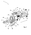
Fig. 1 eine erfindungsgemäße Vorrichtung in perspektivischer Darstellung; -
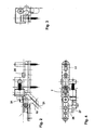
Fig. 2 eine erfindungsgemäße Vorrichtung in einer Seitenansicht; -
Fig. 3 die inFig. 2 dargestellte Vorrichtung in stirnseitiger Ansicht; -
Fig. 4 die inFig. 2 dargestellte Vorrichtung in Draufsicht; -
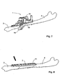
Fig. 5 eine schematische Darstellung des Anordnens einer erfindungsgemäßen Vorrichtung auf einem Knochen; -
Fig. 6 eine schematische Darstellung des Durchtrennens eines Knochens; -
Fig. 7 eine schematische Darstellung ähnlichFig. 6 nach Entnahme eines Knochenstücks; -
Fig. 8 einen Knochen mit einer befestigten Knochenplatte. - In
Fig. 1 bis 4 ist eine erfindungsgemäße Vorrichtung 1 in verschiedenen Ansichten dargestellt. Die Vorrichtung 1 umfasst eine Knochenplatte 5, die ein endseitiges Loch 6 aufweist, das in Draufsicht etwa rund ausgebildet ist. Daneben weist die Knochenplatte 5 ein Langloch 7 sowie ein weiteres Langloch 11 auf, deren Positionen bzw. Lagen noch später erläutert werden. Die Knochenplatte 5 ist länglich ausgebildet und besteht in der Regel aus einem Metall wie Titan. - Auf der Knochenplatte 5 ist ein Block 12 angeordnet. Der Block 12 ist bodenseitig mit zwei sich entlang der Knochenplatte 5 erstreckenden Fortsätzen ausgebildet, die gemeinsam eine weitere Platte 10 definieren. Die weitere Platte 10 bzw. die Fortsätze des Blockes 12 sind mit Befestigungsmitteln 24, 25, z. B. Schrauben, lösbar auf der Knochenplatte 5 befestigt. An einem dem endseitig angeordneten Loch 6 der Knochenplatte 5 gegenüberliegenden Ende derselben erstreckt sich die weitere Platte 10 bzw. der entsprechende Fortsatz des Blockes 12 etwa bis zum Ende der Knochenplatte 5 und weist in diesem endseitigen Bereich ein Langloch 16 auf. Dieses Langloch 16 ist oberhalb des mit korrespondierender Dimensionierung ausgebildeten weiteren Langlochs 11 der Knochenplatte 5 positioniert. Das Langloch 11 ist in
Fig. 1 bis 4 teilweise durch die weitere Platte 10 verdeckt und erst nach Abnahme der weiteren Platte 10 deutlich ersichtlich. In diesem Bereich ist die weitere Platte 10 mit einer Breite ausgebildet, die etwa jener der Knochenplatte 5 entspricht. - Der übrige Teil der weiteren Platte 10 bzw. des Fortsatzes des Blockes 12, der sich vom Block 12 zum endseitigen Loch 6 der Knochenplatte 5 erstreckt, ist in einem an den Block 12 anschließenden Bereich so ausgebildet, dass die weitere Platte 10 im Bereich des Befestigungsmittels 24 auf einer Seite etwa bündig mit der Knochenplatte 5 abschließt, auf der anderen Seite jedoch eine in Richtung des Lochs 6 der Knochenplatte 5 ragende Zunge 26 aufweist, was insbesondere aus
Fig. 2 bis 4 ersichtlich ist. Die Zunge 26 weist außenseitig eine etwa parallel zur Knochenplatte 5 verlaufende Schiene 27 auf. Auf der Schiene 27 ist eine Führungseinrichtung 19 angeordnet. Die Führungseinrichtung 19 weist einen Führungsschlitz 21 auf, durch welchen beispielsweise eine Säge geführt werden kann, sodass die Säge während eines Durchtrennens einer Ulna die durch den Führungsschlitz 21 definierte Ebene nicht verlässt. Ein oberer Teil der Führungseinrichtung 19 umfasst die Schiene 27. Zu diesem Zweck ist die Führungseinrichtung 19 mit einer einem Profil der Schiene 27 entsprechenden Nut ausgebildet. Im oberen Teil der Führungseinrichtung 19 befindet sich des Weiteren eine Skala 22, anhand welcher eine Position der Führungseinrichtung 19 relativ zur weiteren Platte 10, gegenüber welcher die Führungseinrichtung 19 verschiebbar ist, ablesbar ist. Zu diesem Zweck ist auf der weiteren Platte 10 eine Markierung angebracht. Die Verschiebbarkeit der Führungseinrichtung 19 wird dadurch erreicht, dass die Führungseinrichtung 19 eine waagrecht verlaufende seitliche Öffnung aufweist, in der ein in die Schiene 27 eingreifendes Halteelement 28 angeordnet ist, das gelöst werden kann, sodass die Führungseinrichtung 19 entlang der Öffnung, je nach Bedarf bzw. Länge eines zu entnehmenden Knochenstücks, verschoben werden kann. Aufgrund der vorgesehenen Skala 22 kann eine Länge des zu entnehmenden Knochenstücks genau eingestellt werden. Dabei ist gleichzeitig der Vorteil gegeben, dass für zwei vorzunehmende Schnitte jeweils der gleiche Führungsschlitz 21 als Führungsmittel Anwendung findet, was darin resultiert, dass zwei im Wesentlichen parallele Trennebenen erhalten werden, was sich nach Entnahme eines Knochenstücks und Zusammenführen von Teilen einer Ulna bzw. beim Zusammenwachsen der Teile als günstig erweist. Wie beispielsweise ausFig. 2 ersichtlich ist, ist der Führungsschlitz 21 in einem unteren Teil der Führungseinrichtung 19 angeordnet und verläuft etwa in einem Winkel von 45° zur Knochenplatte 5. - Der Block 12 ist etwa mittig auf der Knochenplatte 5 angeordnet. Wie erwähnt ist der Block 12 mit bodenseitigen Fortsätzen ausgebildet, die eine weitere Platte 10 definieren. Dies ist in Bezug auf eine einfache Handhabung der Vorrichtung 1 von Vorteil. Möglich ist es aber auch, dass der Block 12 und die weitere Platte 10 getrennt ausgeführt sind. In diesem Fall liegt der Block 12 auf der weiteren Platte 10 auf. Der Block 12 weist eine zentrale Öffnung 13 auf. Eine Länge dieser Öffnung 13 ist so bemessen, dass diese zumindest das darunterliegende Langloch 7 der Knochenplatte 5 überdeckt. Dadurch kann ein Halteelement 9 in der Öffnung 13 des Blockes 12 positioniert werden. Ein weiteres Halteelement 18 wird im Einsatz in den Langlöchern 7, 11 der Knochenplatte 5 bzw. der weiteren Platte 10 positioniert.
- Wie aus
Fig. 1 bis 4 ersichtlich ist, ist in der Öffnung 13 des Blockes 12 eine Einheit 14 angeordnet. Diese Einheit 14 füllt einen zwischen dem als Zugbolzen ausgebildeten Halteelement 9 und einem Ende der Öffnung 13 liegenden Bereich der Öffnung 13 im Wesentlichen vollständig aus. Die Einheit 14 ist im Bereich des Halteelementes 9 halbrund ausgebildet und umfasst somit das Halteelement 9 bzw. den Zugbolzen. Die Einheit 14 ist mit einem Haltemittel 29 lösbar fixiert. Das Haltemittel 29 bzw. der Haltebolzen durchsetzt den Block 12 und durchragt gemäß der Darstellung inFig. 1 seitliche Ausnehmungen 17 des Blockes 12 normal zur Knochenplatte 5. In den seitlich vorragenden Teil des Haltemittels 29 greift ein Stellelement 15, nämlich eine Stellschraube ein. Das als Stellschraube ausgebildete Stellelement 15 durchsetzt den Block 12 parallel zur Verschieberichtung bzw. der Knochenplatte 5 und liegt auf Höhe des Haltemittels 29. Ist die Vorrichtung 1 in der inFig. 1 dargestellten Form auf einer Ulna befestigt und bereits ein Knochenstück entnommen, so können zwei voneinander getrennte und beabstandete Teile der Ulna durch Drehen der Stellschraube zueinander bewegt werden, bis diese aneinander anliegen. Da sich bei drehender Stellschraube die Einheit 14 nicht bewegt, muss sich der übrige Teil des Blockes 12 mit der verbundenen Knochenplatte 5 in der inFig. 1 durch einen Pfeil angezeigten Verschieberichtung bewegen, wobei das Halteelement 9 einen freien Bereich 23 der Öffnung 13 zumindest teilweise durchläuft. Der übrige Teil des Blockes 12 läuft dabei über das Haltemittel 29. - Anhand der
Fig. 5 bis 8 ist die Verwendung der Vorrichtung 1 gemäßFig. 1 bis 4 bei einer Operation bzw. einer Verkürzung einer Ulna schematisch dargestellt. Die Vorrichtung 1 wird auf einen Knochen 2 wie eine Ulna aufgesetzt, nachdem der Knochen 2 für die Operation freigelegt worden ist. Nach Aufsetzen der Vorrichtung 1 wird diese endseitig am Loch 6 mit einem Befestigungselement 8 wie einer Schraube am Knochen 2 fixiert. Des Weiteren werden in der Öffnung 13 des Blockes 12 bzw. im Langloch 7 der Knochenplatte 5 und den endseitigen Langlöchern 11, 16 die fußseitig ein Gewinde aufweisenden Halteelemente 9, 18 angeordnet und im Knochen 2 befestigt. Hierfür wird, wie ausFig. 5 ersichtlich ist, in den freien Bereich 23 der Öffnung 13 ein passender Adapter 30 eingeführt. Dieser Adapter 30 ist passgenau für den freien Bereich 23 bzw. die Langlöcher 7, 11, 16 ausgebildet und weist eine vertikal verlaufende Öffnung auf, durch welche ein Bohrer 31 geführt werden kann. Aufgrund einer dimensionsgleichen Ausbildung des freien Bereichs 23 und der Langlöcher 7, 11, 16 ist der Adapter 30 mehrfach einsetzbar und dient sowohl beim Bohren eines Lochs im Knochen 2 für das Halteelement 9 als auch das Halteelement 18 als Führungs- und Positionierhilfe. - Ist die Vorrichtung 1 am Knochen 2 befestigt, so kann mit einem geeigneten Schneidgerät 20 eine erste Durchtrennung des Knochens 2 vorgenommen werden (
Fig. 6 ). Nach erfolgtem ersten Durchtrennen des Knochens 2 wird das Halteelement 28 gelöst und die Führungseinrichtung 19 entsprechend einer Länge eines zu entnehmenden Knochenstücks auf der Schiene 27 verschoben und anschließend mit dem Halteelement 28 wieder fixiert, ehe ein zweiter Schnitt vorgenommen wird. Im Anschluss an den zweiten Schnitt wird das Knochenstück vorbestimmter Länge entnommen. Es ist nun eine wie inFig. 7 dargestellte Situation erreicht, wobei Knochenteile 3, 4 noch voneinander beabstandet sind. Die durch Entnahme des Knochenstücks entstandene Lücke ist inFig. 7 durch die Führungseinrichtung 19 der Vorrichtung 1 verdeckt. Mithilfe der Stellschraube bzw. des Stellelementes 15 wird nun der Knochenteil 3 in der zuvor beschriebenen Art zum Knochenteil 4 bewegt. Sobald der Knochenteil 3 am Knochenteil 4 anliegt, kann die Knochenplatte 5 auch am Knochenteil 4 fixiert werden. Wenn die Knochenplatte 5 mit Schrauben an beiden Knochenteilen 3, 4 fixiert ist, kann die Vorrichtung 1 abgenommen werden. Es ist dann eine inFig. 8 dargestellte Situation erreicht. Bei Bedarf kann noch eine weitere Schraube in den Knochen getrieben werden, und zwar schräg im Bereich der Verbindungsflächen der Knochenteile 3, 4, sodass die Knochenteile 3, 4 zusätzlich aneinandergepresst gehalten werden.
Claims (16)
- Vorrichtung (1) zum Verkürzen eines länglichen Knochens (2), insbesondere einer Ulna, umfassend ein Halteelement (9) und eine am Knochen (2) anzubringende Knochenplatte (5) mit einem Loch (6) für ein Befestigungselement (8) zum Fixieren der Knochenplatte (5) am Knochen (2) und einem längs dazu versetzten Langloch (7) für das Halteelement (9), das im Knochen (2) befestigbar ist, sodass Knochenteile (3, 4) nach Durchtrennen des Knochens (2) und Entnahme eines Knochenstücks im Bereich zwischen dem Loch (6) und dem Langloch (7) durch Verschieben der Knochenplatte (5) relativ zum Halteelement (9) zusammenführbar sind, dadurch gekennzeichnet, dass auf der Knochenplatte (5) im Bereich des Langlochs (7) ein Block (12) mit einer in Draufsicht länglichen und über dem Langloch (7) liegenden Öffnung (13) für das Halteelement (9) angeordnet ist, wobei in der Öffnung (13) eine Einheit (14) des Blockes (12) angeordnet ist, an welcher das Halteelement (9) in Verschieberichtung zur Anlage kommt und relativ zu welcher der übrige Teil des Blockes (12) mithilfe eines vorgesehenen Stellelementes (15) verschiebbar ist.
- Vorrichtung (1) nach Anspruch 1, dadurch gekennzeichnet, dass die Knochenplatte (5) länglich ausgebildet ist.
- Vorrichtung (1) nach Anspruch 1 oder 2, dadurch gekennzeichnet, dass der Block (12) bodenseitig mit Fortsätzen ausgebildet ist, die eine weitere Platte (10) definieren, die zumindest teilweise etwa mit einer gleichen Breite wie die Knochenplatte (5), jedoch kürzer ausgebildet ist.
- Vorrichtung (1) nach Anspruch 3, dadurch gekennzeichnet, dass die weitere Platte (10) ein Langloch (16) und die Knochenplatte (5) ein weiteres Langloch (11) aufweist, welche Langlöcher (11, 16) übereinander angeordnet sind und sich an einem dem Loch (6) gegenüberliegenden Ende der Knochenplatte (5) befinden.
- Vorrichtung (1) nach Anspruch 4, dadurch gekennzeichnet, dass das Halteelement (9) und ein weiteres Halteelement (18) vorgesehen sind, wobei das Halteelement (9) in das Langloch (7) der Knochenplatte (5) und die Öffnung (13) des Blockes (12) und das weitere Halteelement (18) in das weitere Langloch (11) der Knochenplatte (5) und in das Langloch (16) der weiteren Platte (10) eingreifen und länglich mit einem zylindrischen Teil und einem ein Gewinde aufweisenden Teil gebildet sind, wobei der zylindrische Teil des Halteelementes (9) im Block (12) an der Einheit (14) und der zylindrische Teil des weiteren Halteelementes (18) auf der weiteren Platte (10) anliegt.
- Vorrichtung (1) nach Anspruch 5, dadurch gekennzeichnet, dass die Langlöcher (7, 11) der Knochenplatte (5) und ein freier Bereich der Öffnung (23), in den das Halteelement (9) eingeführt ist, und das Langloch (16) der weiteren Platte (10) mit etwa gleichen Abmessungen ausgebildet sind.
- Vorrichtung (1) nach einem der Ansprüche 3 bis 6, dadurch gekennzeichnet, dass die weitere Platte (10) lösbar auf der Knochenplatte (5) angebracht ist.
- Vorrichtung (1) nach einem der Ansprüche 3 bis 7, dadurch gekennzeichnet, dass an der weiteren Platte (10) eine Führungseinrichtung (19) für ein Schneidgerät (20) lösbar befestigt ist.
- Vorrichtung (1) nach Anspruch 8, dadurch gekennzeichnet, dass die Führungseinrichtung (19) relativ zur weiteren Platte (10) variabel fixierbar ist.
- Vorrichtung (1) nach Anspruch 8 oder 9, dadurch gekennzeichnet, dass die Führungseinrichtung (19) einen Führungsschlitz (21) und eine Skala (22) aufweist, an welcher eine Position der Führungseinrichtung (19) relativ zur weiteren Platte (10) ablesbar ist.
- Vorrichtung (1) nach einem der Ansprüche 8 bis 10, dadurch gekennzeichnet, dass die Führungseinrichtung (19) lösbar auf der weiteren Platte (10) befestigt ist.
- Vorrichtung (1) nach einem der Ansprüche 1 bis 11, dadurch gekennzeichnet, dass der übrige Teil des Blockes (12) durch das Stellelement (15) kontinuierlich verschiebbar ist.
- Vorrichtung (1) nach einem der Ansprüche 1 bis 12, dadurch gekennzeichnet, dass die Einheit (14) das Halteelement (9) teilweise umfasst.
- Vorrichtung (1) nach einem der Ansprüche 1 bis 13, dadurch gekennzeichnet, dass das Stellelement (15) als Stellschraube ausgebildet ist, welche im oder am übrigen Teil des Blockes (12) angeordnet ist und mit der Einheit (14) in Verbindung steht.
- Vorrichtung (1) nach Anspruch 14, dadurch gekennzeichnet, dass die Stellschraube etwa parallel zur Knochenplatte (5) in Verschieberichtung verläuft.
- Vorrichtung (1) nach einem der Ansprüche 1 bis 15, dadurch gekennzeichnet, dass die Einheit (14) in die Öffnung (13) einsetzbar ist und der Block (12) in Verschieberichtung verlaufende seitliche Ausnehmungen (17) aufweist, durch welche ein mit dem Stellelement (15) in Verbindung stehendes und die Einheit (14) vertikal in Position haltendes Haltemittel (29) geführt ist.
Applications Claiming Priority (2)
| Application Number | Priority Date | Filing Date | Title |
|---|---|---|---|
| AT0185108A AT506937B1 (de) | 2008-11-27 | 2008-11-27 | Vorrichtung zum verkürzen eines länglichen knochens |
| PCT/AT2009/000405 WO2010060124A1 (de) | 2008-11-27 | 2009-10-19 | Vorrichtung zum verkürzen eines länglichen knochens |
Publications (2)
| Publication Number | Publication Date |
|---|---|
| EP2361047A1 EP2361047A1 (de) | 2011-08-31 |
| EP2361047B1 true EP2361047B1 (de) | 2014-12-17 |
Family
ID=41479642
Family Applications (1)
| Application Number | Title | Priority Date | Filing Date |
|---|---|---|---|
| EP09744021.8A Active EP2361047B1 (de) | 2008-11-27 | 2009-10-19 | Vorrichtung zum verkürzen eines länglichen knochens |
Country Status (5)
| Country | Link |
|---|---|
| US (1) | US8777948B2 (de) |
| EP (1) | EP2361047B1 (de) |
| AT (1) | AT506937B1 (de) |
| WO (1) | WO2010060124A1 (de) |
| ZA (1) | ZA201104643B (de) |
Families Citing this family (56)
| Publication number | Priority date | Publication date | Assignee | Title |
|---|---|---|---|---|
| GB2465625B (en) * | 2008-11-27 | 2011-06-08 | Osteotec Ltd | Adjustable excision device for bones |
| FR2968190B1 (fr) | 2010-12-01 | 2013-09-27 | D L P Sarl | Equipement pour la mise en compression de deux parties osseuses |
| US9907558B2 (en) | 2011-07-08 | 2018-03-06 | Smith & Nephew, Inc. | Osteotomy guide and method |
| CA2857992C (en) | 2011-12-09 | 2018-08-14 | Zimmer Gmbh | Orthopedic plate, orthopedic device, method of coupling bone segments, and method of assembling an orthopedic plate |
| US10441329B2 (en) | 2013-10-28 | 2019-10-15 | Jace Medical, Llc | Orthopedic fixation device, system and method |
| US20160015426A1 (en) | 2014-07-15 | 2016-01-21 | Treace Medical Concepts, Inc. | Bone positioning and cutting system and method |
| WO2016029008A1 (en) | 2014-08-20 | 2016-02-25 | Jace Medical, Llc | Implant positioning devices and methods |
| US9687250B2 (en) | 2015-01-07 | 2017-06-27 | Treace Medical Concepts, Inc. | Bone cutting guide systems and methods |
| US10898211B2 (en) | 2015-01-14 | 2021-01-26 | Crossroads Extremity Systems, Llc | Opening and closing wedge osteotomy guide and method |
| US10292713B2 (en) | 2015-01-28 | 2019-05-21 | First Ray, LLC | Freeform tri-planar osteotomy guide and method |
| US10849631B2 (en) | 2015-02-18 | 2020-12-01 | Treace Medical Concepts, Inc. | Pivotable bone cutting guide useful for bone realignment and compression techniques |
| US10376268B2 (en) | 2015-02-19 | 2019-08-13 | First Ray, LLC | Indexed tri-planar osteotomy guide and method |
| US9622805B2 (en) | 2015-08-14 | 2017-04-18 | Treace Medical Concepts, Inc. | Bone positioning and preparing guide systems and methods |
| CA3281165A1 (en) | 2015-07-14 | 2025-10-31 | Treace Medical Concepts, Inc. | Bone positioning guide |
| US10849663B2 (en) | 2015-07-14 | 2020-12-01 | Treace Medical Concepts, Inc. | Bone cutting guide systems and methods |
| EP4494582A3 (de) | 2015-08-14 | 2025-04-16 | Treace Medical Concepts, Inc. | Tarsal-metatarsales gelenkverfahren mit drehpunkt |
| EP3334356B1 (de) | 2015-08-14 | 2024-10-02 | Treace Medical Concepts, Inc. | Drehpunkt zur verwendung bei der behandlung des tarsometatarsalgelenk |
| EP4740879A2 (de) | 2015-09-18 | 2026-05-13 | Treace Medical Concepts, Inc. | Gemeinsame abstandshaltersysteme |
| US10512470B1 (en) | 2016-08-26 | 2019-12-24 | Treace Medical Concepts, Inc. | Osteotomy procedure for correcting bone misalignment |
| US10524808B1 (en) | 2016-11-11 | 2020-01-07 | Treace Medical Concepts, Inc. | Devices and techniques for performing an osteotomy procedure on a first metatarsal to correct a bone misalignment |
| CN107028640B (zh) * | 2017-05-27 | 2023-07-18 | 辽宁省肿瘤医院 | 一种肢体骨截骨导板及其使用方法 |
| US10588644B2 (en) * | 2017-08-31 | 2020-03-17 | DePuy Synthes Products, Inc. | Guide attachment for power tools |
| IT201800002438A1 (it) * | 2018-02-06 | 2019-08-06 | St Ortopedico Rizzoli | Strumentario per l’impianto di inserti ossei |
| BR112020026950A2 (pt) | 2018-07-03 | 2021-03-30 | Trimed, Incorporated | Método e sistema para alterar uma configuração de um osso |
| AU2019302676B2 (en) | 2018-07-11 | 2025-03-06 | Treace Medical Concepts, Inc. | Compressor-distractor for angularly realigning bone portions |
| WO2020014660A1 (en) | 2018-07-12 | 2020-01-16 | Treace Medical Concepts, Inc. | Multi-diameter bone pin for installing and aligning bone fixation plate while minimizing bone damage |
| US11607250B2 (en) | 2019-02-13 | 2023-03-21 | Treace Medical Concepts, Inc. | Tarsal-metatarsal joint procedure utilizing compressor-distractor and instrument providing sliding surface |
| EP4003192A4 (de) | 2019-07-26 | 2023-08-02 | Crossroads Extremity Systems, LLC | Führungssystem und -verfahren zur knochenrückstellung |
| CA3146564A1 (en) | 2019-08-07 | 2021-02-11 | Jason May | Bi-planar instrument for bone cutting and joint realignment procedure |
| US11889998B1 (en) | 2019-09-12 | 2024-02-06 | Treace Medical Concepts, Inc. | Surgical pin positioning lock |
| US12490992B2 (en) | 2019-09-13 | 2025-12-09 | Treace Medical Concepts, Inc. | Patient-specific surgical methods and instrumentation |
| US11986251B2 (en) | 2019-09-13 | 2024-05-21 | Treace Medical Concepts, Inc. | Patient-specific osteotomy instrumentation |
| US11890039B1 (en) | 2019-09-13 | 2024-02-06 | Treace Medical Concepts, Inc. | Multi-diameter K-wire for orthopedic applications |
| WO2021051098A1 (en) | 2019-09-13 | 2021-03-18 | Inmotus Medical Llc | Patient-specific surgical methods and instrumentation |
| US11026698B2 (en) * | 2019-10-29 | 2021-06-08 | Skeletal Dynamics, Inc. | Osteotomy system and method of use |
| AU2021212261A1 (en) | 2020-01-31 | 2022-08-18 | Treace Medical Concepts, Inc. | Metatarsophalangeal joint preparation and metatarsal realignment for fusion |
| CN115297791A (zh) | 2020-02-19 | 2022-11-04 | 汇聚义肢系统有限责任公司 | 用于拇囊炎的lapidus修复的系统和方法 |
| JP7769637B2 (ja) | 2020-05-19 | 2025-11-13 | トリース メディカル コンセプツ,インコーポレイティド | 中足骨内転を治療するための装置及び技術 |
| CN111772728A (zh) * | 2020-07-06 | 2020-10-16 | 深圳市鑫君特智能医疗器械有限公司 | 智能截骨系统及截骨装置 |
| JP7759952B2 (ja) | 2021-01-18 | 2025-10-24 | トリース メディカル コンセプツ,インコーポレイティド | 特に足根中足関節にわたる骨圧縮のための係止ねじを有する輪郭形成された骨プレート |
| US12310603B2 (en) | 2021-02-18 | 2025-05-27 | Treace Medical Concepts, Inc. | System and technique for metatarsal realignment with reduced incision length |
| US11457931B1 (en) | 2021-03-31 | 2022-10-04 | Avanti Orthopaedics Llc | Bone shortening osteotomy apparatus |
| WO2022246282A1 (en) | 2021-05-20 | 2022-11-24 | Treace Medical Concepts, Inc. | Cut guide with integrated joint realignment features |
| US11883075B2 (en) * | 2021-11-08 | 2024-01-30 | Relja Innovations, Llc | Device and surgical technique for foot surgery |
| USD1101146S1 (en) | 2022-02-23 | 2025-11-04 | Treace Medical Concepts, Inc. | Multi-sided cutting instrument for mobilizing small bones in the foot |
| US12599389B2 (en) | 2022-02-23 | 2026-04-14 | Treace Medical Concepts, Inc. | Multi-sided cutting instrument for mobilizing small bones in the foot |
| CA3244723A1 (en) | 2022-02-23 | 2023-08-31 | Treace Medical Concepts, Inc. | FIRST METATARSAL LATERAL RELEASE INSTRUMENT AND TECHNIQUE |
| USD1079011S1 (en) | 2022-02-23 | 2025-06-10 | Treace Medical Concepts, Inc. | Metatarsal cut guide with parallel cut faces |
| USD1011524S1 (en) | 2022-02-23 | 2024-01-16 | Treace Medical Concepts, Inc. | Compressor-distractor for the foot |
| USD1051382S1 (en) | 2022-02-23 | 2024-11-12 | Treace Medical Concepts, Inc. | Lesser metatarsal cut guide |
| USD1057155S1 (en) | 2022-02-23 | 2025-01-07 | Treace Medical Concepts, Inc. | Lesser metatarsal cut guide with parallel cut faces |
| USD1075012S1 (en) | 2022-02-23 | 2025-05-13 | Treace Medical Concepts, Inc. | Metatarsal lateral release instrument |
| US12478381B2 (en) | 2022-02-24 | 2025-11-25 | Treace Medical Concepts, Inc | Devices and techniques for treating lesser metatarsals of the foot |
| USD1068077S1 (en) | 2023-02-08 | 2025-03-25 | Treace Medical Concepts, Inc. | Orthopedic rasp for preparing an intercuneiform joint |
| USD1068078S1 (en) | 2023-02-08 | 2025-03-25 | Treace Medical Concepts, Inc. | Handle for an orthopedic instrument |
| CN116942288B (zh) * | 2023-09-11 | 2025-12-05 | 中国人民解放军32298部队 | 一种复位固定钳 |
Family Cites Families (6)
| Publication number | Priority date | Publication date | Assignee | Title |
|---|---|---|---|---|
| US4929247A (en) * | 1988-10-06 | 1990-05-29 | Rayhack John M | Bone compression and distraction device |
| US5042983A (en) * | 1989-10-30 | 1991-08-27 | Rayhack John M | Precision bone cutting guide |
| US8652142B2 (en) | 2006-04-28 | 2014-02-18 | Acumed Llc | Osteotomy systems |
| US20060118118A1 (en) | 2003-10-29 | 2006-06-08 | Smaldone Gerald C | Drug delivery systems |
| US7540874B2 (en) * | 2004-05-27 | 2009-06-02 | Trimed Inc. | Method and device for use in osteotomy |
| US20070276383A1 (en) * | 2006-05-11 | 2007-11-29 | Rayhack L.L.C. | Osteotomy system |
-
2008
- 2008-11-27 AT AT0185108A patent/AT506937B1/de active
-
2009
- 2009-10-19 EP EP09744021.8A patent/EP2361047B1/de active Active
- 2009-10-19 US US13/131,473 patent/US8777948B2/en active Active
- 2009-10-19 WO PCT/AT2009/000405 patent/WO2010060124A1/de not_active Ceased
-
2011
- 2011-06-23 ZA ZA2011/04643A patent/ZA201104643B/en unknown
Also Published As
| Publication number | Publication date |
|---|---|
| WO2010060124A1 (de) | 2010-06-03 |
| US8777948B2 (en) | 2014-07-15 |
| US20110238068A1 (en) | 2011-09-29 |
| EP2361047A1 (de) | 2011-08-31 |
| AT506937A4 (de) | 2010-01-15 |
| ZA201104643B (en) | 2012-03-28 |
| AT506937B1 (de) | 2010-01-15 |
Similar Documents
| Publication | Publication Date | Title |
|---|---|---|
| AT506937B1 (de) | Vorrichtung zum verkürzen eines länglichen knochens | |
| EP0259312B1 (de) | Vorrichtung zur osteotomie | |
| DE102007053058B3 (de) | Chirurgische Sägelehre sowie Sägelehrensatz | |
| DE69510462T2 (de) | Einrichtung zur vorläufigen fixierung zweier knochenteile | |
| EP1470787B1 (de) | Vorrichtung zur Vorbereitung einer Femurkondyle | |
| DE60216667T2 (de) | Vorrichtung zur Positionierung der Schnittebene einer Knochensägenführung | |
| DE69519169T2 (de) | Mechanische vorrichtung zum ausrichten von knochenschrauben,die in einem marknagel einzulassen sind | |
| DE2712696C3 (de) | Kieferdehnschraube | |
| EP0951868B1 (de) | Chirurgischer Spreizer | |
| EP1476084A1 (de) | Sägelehre für medizinische zwecke | |
| EP0374086A1 (de) | Sägelehrensystem | |
| DE10153467B4 (de) | Vorrichtung zur Stabilisierung der Tibia und/oder des Tibiakopfes nach Osteotomie-Eingriffen | |
| DE2919935C2 (de) | Vorrichtung zur Führung chirurgischer Instrumente bei Operationen an Röhrenknochen | |
| DE102015105931A1 (de) | Medizinische Führungsvorrichtung | |
| DE2808911C2 (de) | Stanze zum Abtragen von Knochen und Knorpel | |
| EP1900465B1 (de) | Vorrichtung zur Führung eines Sägeblattes | |
| DE2939057C3 (de) | Schneidvorrichtung zum Einbringen von Schnitten in die Haut | |
| DE10301688B3 (de) | System und Vorrichtung zum Messen von Knochenschrauben | |
| EP1348514A2 (de) | Schlittensystem | |
| DE10107766A1 (de) | Schneidvorrichtung zur Durchführung von Gehrungsschnitten an Leisten | |
| DE19811354A1 (de) | Vorrichtung für Osteosynthesearbeiten sowie zur Vorrichtung angepaßter Fixationsstift zur Osteosynthese | |
| EP3702100B1 (de) | Anschlagvorrichtung | |
| DE202012101070U1 (de) | Stanzwerkzeug für Flachbandkabel | |
| DE202009011644U1 (de) | Schweißlehre | |
| DE3211153A1 (de) | Vorrichtung zum einstellen und festlegen der schnittebene bei knochenschnitten |
Legal Events
| Date | Code | Title | Description |
|---|---|---|---|
| PUAI | Public reference made under article 153(3) epc to a published international application that has entered the european phase |
Free format text: ORIGINAL CODE: 0009012 |
|
| 17P | Request for examination filed |
Effective date: 20110503 |
|
| AK | Designated contracting states |
Kind code of ref document: A1 Designated state(s): AT BE BG CH CY CZ DE DK EE ES FI FR GB GR HR HU IE IS IT LI LT LU LV MC MK MT NL NO PL PT RO SE SI SK SM TR |
|
| DAX | Request for extension of the european patent (deleted) | ||
| 17Q | First examination report despatched |
Effective date: 20140224 |
|
| GRAP | Despatch of communication of intention to grant a patent |
Free format text: ORIGINAL CODE: EPIDOSNIGR1 |
|
| INTG | Intention to grant announced |
Effective date: 20140829 |
|
| GRAS | Grant fee paid |
Free format text: ORIGINAL CODE: EPIDOSNIGR3 |
|
| GRAA | (expected) grant |
Free format text: ORIGINAL CODE: 0009210 |
|
| AK | Designated contracting states |
Kind code of ref document: B1 Designated state(s): AT BE BG CH CY CZ DE DK EE ES FI FR GB GR HR HU IE IS IT LI LT LU LV MC MK MT NL NO PL PT RO SE SI SK SM TR |
|
| REG | Reference to a national code |
Ref country code: GB Ref legal event code: FG4D Free format text: NOT ENGLISH |
|
| REG | Reference to a national code |
Ref country code: CH Ref legal event code: EP |
|
| REG | Reference to a national code |
Ref country code: IE Ref legal event code: FG4D Free format text: LANGUAGE OF EP DOCUMENT: GERMAN |
|
| REG | Reference to a national code |
Ref country code: AT Ref legal event code: REF Ref document number: 701292 Country of ref document: AT Kind code of ref document: T Effective date: 20150115 |
|
| REG | Reference to a national code |
Ref country code: DE Ref legal event code: R096 Ref document number: 502009010365 Country of ref document: DE Effective date: 20150129 |
|
| REG | Reference to a national code |
Ref country code: NL Ref legal event code: T3 |
|
| REG | Reference to a national code |
Ref country code: CH Ref legal event code: NV Representative=s name: KELLER AND PARTNER PATENTANWAELTE AG, CH |
|
| PG25 | Lapsed in a contracting state [announced via postgrant information from national office to epo] |
Ref country code: NO Free format text: LAPSE BECAUSE OF FAILURE TO SUBMIT A TRANSLATION OF THE DESCRIPTION OR TO PAY THE FEE WITHIN THE PRESCRIBED TIME-LIMIT Effective date: 20150317 Ref country code: LT Free format text: LAPSE BECAUSE OF FAILURE TO SUBMIT A TRANSLATION OF THE DESCRIPTION OR TO PAY THE FEE WITHIN THE PRESCRIBED TIME-LIMIT Effective date: 20141217 Ref country code: FI Free format text: LAPSE BECAUSE OF FAILURE TO SUBMIT A TRANSLATION OF THE DESCRIPTION OR TO PAY THE FEE WITHIN THE PRESCRIBED TIME-LIMIT Effective date: 20141217 |
|
| REG | Reference to a national code |
Ref country code: LT Ref legal event code: MG4D |
|
| PG25 | Lapsed in a contracting state [announced via postgrant information from national office to epo] |
Ref country code: SE Free format text: LAPSE BECAUSE OF FAILURE TO SUBMIT A TRANSLATION OF THE DESCRIPTION OR TO PAY THE FEE WITHIN THE PRESCRIBED TIME-LIMIT Effective date: 20141217 Ref country code: HR Free format text: LAPSE BECAUSE OF FAILURE TO SUBMIT A TRANSLATION OF THE DESCRIPTION OR TO PAY THE FEE WITHIN THE PRESCRIBED TIME-LIMIT Effective date: 20141217 Ref country code: GR Free format text: LAPSE BECAUSE OF FAILURE TO SUBMIT A TRANSLATION OF THE DESCRIPTION OR TO PAY THE FEE WITHIN THE PRESCRIBED TIME-LIMIT Effective date: 20150318 Ref country code: LV Free format text: LAPSE BECAUSE OF FAILURE TO SUBMIT A TRANSLATION OF THE DESCRIPTION OR TO PAY THE FEE WITHIN THE PRESCRIBED TIME-LIMIT Effective date: 20141217 |
|
| PG25 | Lapsed in a contracting state [announced via postgrant information from national office to epo] |
Ref country code: ES Free format text: LAPSE BECAUSE OF FAILURE TO SUBMIT A TRANSLATION OF THE DESCRIPTION OR TO PAY THE FEE WITHIN THE PRESCRIBED TIME-LIMIT Effective date: 20141217 Ref country code: RO Free format text: LAPSE BECAUSE OF FAILURE TO SUBMIT A TRANSLATION OF THE DESCRIPTION OR TO PAY THE FEE WITHIN THE PRESCRIBED TIME-LIMIT Effective date: 20141217 Ref country code: EE Free format text: LAPSE BECAUSE OF FAILURE TO SUBMIT A TRANSLATION OF THE DESCRIPTION OR TO PAY THE FEE WITHIN THE PRESCRIBED TIME-LIMIT Effective date: 20141217 Ref country code: SK Free format text: LAPSE BECAUSE OF FAILURE TO SUBMIT A TRANSLATION OF THE DESCRIPTION OR TO PAY THE FEE WITHIN THE PRESCRIBED TIME-LIMIT Effective date: 20141217 Ref country code: CZ Free format text: LAPSE BECAUSE OF FAILURE TO SUBMIT A TRANSLATION OF THE DESCRIPTION OR TO PAY THE FEE WITHIN THE PRESCRIBED TIME-LIMIT Effective date: 20141217 |
|
| PG25 | Lapsed in a contracting state [announced via postgrant information from national office to epo] |
Ref country code: IS Free format text: LAPSE BECAUSE OF FAILURE TO SUBMIT A TRANSLATION OF THE DESCRIPTION OR TO PAY THE FEE WITHIN THE PRESCRIBED TIME-LIMIT Effective date: 20150417 Ref country code: PL Free format text: LAPSE BECAUSE OF FAILURE TO SUBMIT A TRANSLATION OF THE DESCRIPTION OR TO PAY THE FEE WITHIN THE PRESCRIBED TIME-LIMIT Effective date: 20141217 |
|
| REG | Reference to a national code |
Ref country code: DE Ref legal event code: R097 Ref document number: 502009010365 Country of ref document: DE |
|
| PLBE | No opposition filed within time limit |
Free format text: ORIGINAL CODE: 0009261 |
|
| STAA | Information on the status of an ep patent application or granted ep patent |
Free format text: STATUS: NO OPPOSITION FILED WITHIN TIME LIMIT |
|
| PG25 | Lapsed in a contracting state [announced via postgrant information from national office to epo] |
Ref country code: DK Free format text: LAPSE BECAUSE OF FAILURE TO SUBMIT A TRANSLATION OF THE DESCRIPTION OR TO PAY THE FEE WITHIN THE PRESCRIBED TIME-LIMIT Effective date: 20141217 |
|
| 26N | No opposition filed |
Effective date: 20150918 |
|
| PG25 | Lapsed in a contracting state [announced via postgrant information from national office to epo] |
Ref country code: SI Free format text: LAPSE BECAUSE OF FAILURE TO SUBMIT A TRANSLATION OF THE DESCRIPTION OR TO PAY THE FEE WITHIN THE PRESCRIBED TIME-LIMIT Effective date: 20141217 |
|
| PG25 | Lapsed in a contracting state [announced via postgrant information from national office to epo] |
Ref country code: LU Free format text: LAPSE BECAUSE OF FAILURE TO SUBMIT A TRANSLATION OF THE DESCRIPTION OR TO PAY THE FEE WITHIN THE PRESCRIBED TIME-LIMIT Effective date: 20151019 |
|
| PG25 | Lapsed in a contracting state [announced via postgrant information from national office to epo] |
Ref country code: MC Free format text: LAPSE BECAUSE OF FAILURE TO SUBMIT A TRANSLATION OF THE DESCRIPTION OR TO PAY THE FEE WITHIN THE PRESCRIBED TIME-LIMIT Effective date: 20141217 |
|
| REG | Reference to a national code |
Ref country code: IE Ref legal event code: MM4A |
|
| REG | Reference to a national code |
Ref country code: FR Ref legal event code: ST Effective date: 20160630 |
|
| PG25 | Lapsed in a contracting state [announced via postgrant information from national office to epo] |
Ref country code: FR Free format text: LAPSE BECAUSE OF NON-PAYMENT OF DUE FEES Effective date: 20151102 |
|
| PG25 | Lapsed in a contracting state [announced via postgrant information from national office to epo] |
Ref country code: IE Free format text: LAPSE BECAUSE OF NON-PAYMENT OF DUE FEES Effective date: 20151019 |
|
| REG | Reference to a national code |
Ref country code: AT Ref legal event code: MM01 Ref document number: 701292 Country of ref document: AT Kind code of ref document: T Effective date: 20151019 |
|
| PG25 | Lapsed in a contracting state [announced via postgrant information from national office to epo] |
Ref country code: AT Free format text: LAPSE BECAUSE OF NON-PAYMENT OF DUE FEES Effective date: 20151019 |
|
| PG25 | Lapsed in a contracting state [announced via postgrant information from national office to epo] |
Ref country code: HU Free format text: LAPSE BECAUSE OF FAILURE TO SUBMIT A TRANSLATION OF THE DESCRIPTION OR TO PAY THE FEE WITHIN THE PRESCRIBED TIME-LIMIT; INVALID AB INITIO Effective date: 20091019 Ref country code: SM Free format text: LAPSE BECAUSE OF FAILURE TO SUBMIT A TRANSLATION OF THE DESCRIPTION OR TO PAY THE FEE WITHIN THE PRESCRIBED TIME-LIMIT Effective date: 20141217 Ref country code: BG Free format text: LAPSE BECAUSE OF FAILURE TO SUBMIT A TRANSLATION OF THE DESCRIPTION OR TO PAY THE FEE WITHIN THE PRESCRIBED TIME-LIMIT Effective date: 20141217 |
|
| PG25 | Lapsed in a contracting state [announced via postgrant information from national office to epo] |
Ref country code: CY Free format text: LAPSE BECAUSE OF FAILURE TO SUBMIT A TRANSLATION OF THE DESCRIPTION OR TO PAY THE FEE WITHIN THE PRESCRIBED TIME-LIMIT Effective date: 20141217 |
|
| PG25 | Lapsed in a contracting state [announced via postgrant information from national office to epo] |
Ref country code: BE Free format text: LAPSE BECAUSE OF NON-PAYMENT OF DUE FEES Effective date: 20151031 |
|
| PG25 | Lapsed in a contracting state [announced via postgrant information from national office to epo] |
Ref country code: TR Free format text: LAPSE BECAUSE OF FAILURE TO SUBMIT A TRANSLATION OF THE DESCRIPTION OR TO PAY THE FEE WITHIN THE PRESCRIBED TIME-LIMIT Effective date: 20141217 Ref country code: MT Free format text: LAPSE BECAUSE OF FAILURE TO SUBMIT A TRANSLATION OF THE DESCRIPTION OR TO PAY THE FEE WITHIN THE PRESCRIBED TIME-LIMIT Effective date: 20141217 |
|
| PG25 | Lapsed in a contracting state [announced via postgrant information from national office to epo] |
Ref country code: MK Free format text: LAPSE BECAUSE OF FAILURE TO SUBMIT A TRANSLATION OF THE DESCRIPTION OR TO PAY THE FEE WITHIN THE PRESCRIBED TIME-LIMIT Effective date: 20141217 |
|
| PG25 | Lapsed in a contracting state [announced via postgrant information from national office to epo] |
Ref country code: PT Free format text: LAPSE BECAUSE OF FAILURE TO SUBMIT A TRANSLATION OF THE DESCRIPTION OR TO PAY THE FEE WITHIN THE PRESCRIBED TIME-LIMIT Effective date: 20141217 |
|
| REG | Reference to a national code |
Ref country code: CH Ref legal event code: PFA Owner name: I.T.S. GMBH, AT Free format text: FORMER OWNER: I.T.S. GMBH, AT |
|
| PGFP | Annual fee paid to national office [announced via postgrant information from national office to epo] |
Ref country code: NL Payment date: 20221019 Year of fee payment: 14 |
|
| PGFP | Annual fee paid to national office [announced via postgrant information from national office to epo] |
Ref country code: IT Payment date: 20221026 Year of fee payment: 14 Ref country code: GB Payment date: 20221020 Year of fee payment: 14 Ref country code: DE Payment date: 20221019 Year of fee payment: 14 |
|
| PGFP | Annual fee paid to national office [announced via postgrant information from national office to epo] |
Ref country code: CH Payment date: 20221026 Year of fee payment: 14 |
|
| REG | Reference to a national code |
Ref country code: DE Ref legal event code: R119 Ref document number: 502009010365 Country of ref document: DE |
|
| REG | Reference to a national code |
Ref country code: CH Ref legal event code: PL |
|
| REG | Reference to a national code |
Ref country code: NL Ref legal event code: MM Effective date: 20231101 |
|
| GBPC | Gb: european patent ceased through non-payment of renewal fee |
Effective date: 20231019 |
|
| PG25 | Lapsed in a contracting state [announced via postgrant information from national office to epo] |
Ref country code: GB Free format text: LAPSE BECAUSE OF NON-PAYMENT OF DUE FEES Effective date: 20231019 |
|
| PG25 | Lapsed in a contracting state [announced via postgrant information from national office to epo] |
Ref country code: NL Free format text: LAPSE BECAUSE OF NON-PAYMENT OF DUE FEES Effective date: 20231101 Ref country code: CH Free format text: LAPSE BECAUSE OF NON-PAYMENT OF DUE FEES Effective date: 20231031 |
|
| PG25 | Lapsed in a contracting state [announced via postgrant information from national office to epo] |
Ref country code: NL Free format text: LAPSE BECAUSE OF NON-PAYMENT OF DUE FEES Effective date: 20231101 Ref country code: GB Free format text: LAPSE BECAUSE OF NON-PAYMENT OF DUE FEES Effective date: 20231019 Ref country code: DE Free format text: LAPSE BECAUSE OF NON-PAYMENT OF DUE FEES Effective date: 20240501 Ref country code: CH Free format text: LAPSE BECAUSE OF NON-PAYMENT OF DUE FEES Effective date: 20231031 |
|
| PG25 | Lapsed in a contracting state [announced via postgrant information from national office to epo] |
Ref country code: IT Free format text: LAPSE BECAUSE OF NON-PAYMENT OF DUE FEES Effective date: 20231019 |
|
| PG25 | Lapsed in a contracting state [announced via postgrant information from national office to epo] |
Ref country code: IT Free format text: LAPSE BECAUSE OF NON-PAYMENT OF DUE FEES Effective date: 20231019 |