EP2360051A2 - Fahrzeugsitz mit einem Sitzversteller - Google Patents
Fahrzeugsitz mit einem Sitzversteller Download PDFInfo
- Publication number
- EP2360051A2 EP2360051A2 EP20110000733 EP11000733A EP2360051A2 EP 2360051 A2 EP2360051 A2 EP 2360051A2 EP 20110000733 EP20110000733 EP 20110000733 EP 11000733 A EP11000733 A EP 11000733A EP 2360051 A2 EP2360051 A2 EP 2360051A2
- Authority
- EP
- European Patent Office
- Prior art keywords
- vehicle seat
- seat
- bearings
- vehicle
- bearing
- Prior art date
- Legal status (The legal status is an assumption and is not a legal conclusion. Google has not performed a legal analysis and makes no representation as to the accuracy of the status listed.)
- Granted
Links
- 230000005540 biological transmission Effects 0.000 claims description 14
- 239000000969 carrier Substances 0.000 claims description 10
- 230000004048 modification Effects 0.000 description 2
- 238000012986 modification Methods 0.000 description 2
- 238000010276 construction Methods 0.000 description 1
- 230000007246 mechanism Effects 0.000 description 1
- NJPPVKZQTLUDBO-UHFFFAOYSA-N novaluron Chemical compound C1=C(Cl)C(OC(F)(F)C(OC(F)(F)F)F)=CC=C1NC(=O)NC(=O)C1=C(F)C=CC=C1F NJPPVKZQTLUDBO-UHFFFAOYSA-N 0.000 description 1
- 210000000689 upper leg Anatomy 0.000 description 1
Images


Classifications
-
- B—PERFORMING OPERATIONS; TRANSPORTING
- B60—VEHICLES IN GENERAL
- B60N—SEATS SPECIALLY ADAPTED FOR VEHICLES; VEHICLE PASSENGER ACCOMMODATION NOT OTHERWISE PROVIDED FOR
- B60N2/00—Seats specially adapted for vehicles; Arrangement or mounting of seats in vehicles
- B60N2/02—Seats specially adapted for vehicles; Arrangement or mounting of seats in vehicles the seat or part thereof being movable, e.g. adjustable
- B60N2/04—Seats specially adapted for vehicles; Arrangement or mounting of seats in vehicles the seat or part thereof being movable, e.g. adjustable the whole seat being movable
- B60N2/16—Seats specially adapted for vehicles; Arrangement or mounting of seats in vehicles the seat or part thereof being movable, e.g. adjustable the whole seat being movable height-adjustable
- B60N2/1605—Seats specially adapted for vehicles; Arrangement or mounting of seats in vehicles the seat or part thereof being movable, e.g. adjustable the whole seat being movable height-adjustable characterised by the cinematic
- B60N2/161—Rods
- B60N2/1615—Parallelogram-like structure
-
- B—PERFORMING OPERATIONS; TRANSPORTING
- B60—VEHICLES IN GENERAL
- B60N—SEATS SPECIALLY ADAPTED FOR VEHICLES; VEHICLE PASSENGER ACCOMMODATION NOT OTHERWISE PROVIDED FOR
- B60N2/00—Seats specially adapted for vehicles; Arrangement or mounting of seats in vehicles
- B60N2/02—Seats specially adapted for vehicles; Arrangement or mounting of seats in vehicles the seat or part thereof being movable, e.g. adjustable
- B60N2/04—Seats specially adapted for vehicles; Arrangement or mounting of seats in vehicles the seat or part thereof being movable, e.g. adjustable the whole seat being movable
- B60N2/045—Longitudinal adjustment by means of articulated rods supporting the seat, e.g. parallelogram mechanisms
-
- B—PERFORMING OPERATIONS; TRANSPORTING
- B60—VEHICLES IN GENERAL
- B60N—SEATS SPECIALLY ADAPTED FOR VEHICLES; VEHICLE PASSENGER ACCOMMODATION NOT OTHERWISE PROVIDED FOR
- B60N2/00—Seats specially adapted for vehicles; Arrangement or mounting of seats in vehicles
- B60N2/02—Seats specially adapted for vehicles; Arrangement or mounting of seats in vehicles the seat or part thereof being movable, e.g. adjustable
- B60N2/04—Seats specially adapted for vehicles; Arrangement or mounting of seats in vehicles the seat or part thereof being movable, e.g. adjustable the whole seat being movable
- B60N2/16—Seats specially adapted for vehicles; Arrangement or mounting of seats in vehicles the seat or part thereof being movable, e.g. adjustable the whole seat being movable height-adjustable
- B60N2/1605—Seats specially adapted for vehicles; Arrangement or mounting of seats in vehicles the seat or part thereof being movable, e.g. adjustable the whole seat being movable height-adjustable characterised by the cinematic
- B60N2/161—Rods
-
- B—PERFORMING OPERATIONS; TRANSPORTING
- B60—VEHICLES IN GENERAL
- B60N—SEATS SPECIALLY ADAPTED FOR VEHICLES; VEHICLE PASSENGER ACCOMMODATION NOT OTHERWISE PROVIDED FOR
- B60N2/00—Seats specially adapted for vehicles; Arrangement or mounting of seats in vehicles
- B60N2/02—Seats specially adapted for vehicles; Arrangement or mounting of seats in vehicles the seat or part thereof being movable, e.g. adjustable
- B60N2/04—Seats specially adapted for vehicles; Arrangement or mounting of seats in vehicles the seat or part thereof being movable, e.g. adjustable the whole seat being movable
- B60N2/16—Seats specially adapted for vehicles; Arrangement or mounting of seats in vehicles the seat or part thereof being movable, e.g. adjustable the whole seat being movable height-adjustable
- B60N2/1605—Seats specially adapted for vehicles; Arrangement or mounting of seats in vehicles the seat or part thereof being movable, e.g. adjustable the whole seat being movable height-adjustable characterised by the cinematic
- B60N2/1625—Combination of rods and slides
Definitions
- the present invention relates to a vehicle seat with a seat part which is connected in its front and in the rear region with two bearings to the body.
- Such vehicle seats are known from the prior art, for example KR 10 013 1939 B1 , of the FR 28 648 09 , of the DE 10 2006 031 466 A1 , of the DE 40 104 51 C2 , of the DE 10 149 858 C2 , of the GB 23 724 38 , of the CA 26 710 03 , of the WO 02/81870 A1 , of the DE 42 409 43 A1 , as well as the DE 40 104 51 A1 known.
- the vehicle seats described there are usually used as a driver or passenger seat. For rear seats in motor vehicles, however, these adjustment mechanisms are too expensive.
- the object is achieved with a vehicle seat with a seat part which is connected in its front region and in its rear region with two bearings to the body of the motor vehicle, each bearing is provided as a curved support.
- the present invention relates to a vehicle seat with a seat part and a backrest on which preferably a headrest is provided.
- the vehicle seat according to the invention can accommodate one or more persons. Consequently, the vehicle seat according to the invention can also be a seat.
- the vehicle seat according to the invention in the rear, d. H. behind the driver and the passenger seat, arranged.
- the driver's seat according to the invention is mounted both in its front region, ie the area in which the thighs rest, as well as in its rear region, in which the backrest is arranged, each with two bearings on the body of the vehicle.
- these bearings are each provided in the right and in the left region of the seat part.
- each of these bearings now has a curved carrier, wherein one end of this carrier is rotatably connected to the body and the other end is rotatably connected to the seat part and / or rotatably connected to another carrier.
- the connecting element engages in each case in the curvature region of the carrier.
- Another object of the present invention is a vehicle seat with a seat part, which is connected in its front region and in its rear region with two bearings with the bodywork of the motor vehicle, each bearing is provided as a transmission, each transmission has at least two carriers, which are each provided rotatably to each other and the individual gear are not connected to each other. Each bearing is both rotatably connected to the body and rotatably connected to the seat part.
- each bearing is provided as a gear, wherein each gear has at least two carriers which are each rotatable relative to each other and rotatably provided relative to the body, or the seat portion of the vehicle seat. According to the individual gears are not connected.
- Another object of the present invention is vehicle seat with a seat part, which is connected in its front region and in its rear region with two bearings to the body of the motor vehicle, each bearing of the vehicle seat is provided as a transmission and each gear has a telescopic support ,
- the telekopierbare part of the telescopic support is driven by a drive means, in particular a curve or a gear, wherein the telescopic part is both on and extendable.
- all transmissions have a functionally identical construction, the transmissions being particularly preferably identical in the front or in the rear region.
- Functionally identical means that the gear units are each constructed from the same gear means, which are each provided in an identical operative relationship to each other, however, the length of the respective gear parts may differ.
- the vehicle seat on a locking means, with which it is reversibly lockable in the respective position.
- the vehicle seat is adjustable in the longitudinal direction and / or in its height.
- the longitudinal adjustment is made especially for comfort purposes.
- the height adjustment can for comfort purposes but also for safety reasons, for example, when the vehicle seat according to the invention is used as a child seat, may be provided.
- the height adjustment can be done without an additional drive. It is carried out in a simple manner in the longitudinal adjustment.
- a means is provided on the vehicle seat that supports the adjustment of the seat part of the vehicle seat according to the invention and / or biases into a position.
- the means is an energy store, in particular a spring means.
- the vehicle seat is displaceable only in the longitudinal direction and does not change its height position in this adjustment.
- Another object of the present invention is therefore a vehicle seat, in which the bearings are fixed but rotatably connected to the body and the seat part and in which the seat part is adjustable in at least two positions relative to the body, wherein the adjustment is carried out by a pure translational movement ,
- the longitudinal adjustment thus takes place without a height adjustment.
- All vehicle seats according to the invention have the advantage that a longitudinal adjustment can be made without rails in the vehicle. As a result, weight is paired and no space is lost through the rails.
- FIG. 1 shows the basic structure of the vehicle seat according to the invention F.
- This has a seat part S and a backrest L.
- the seat part S is arranged by means of four bearings on the vehicle body, wherein two bearings 1 are arranged in the front region and two bearings 2 in the rear region of the seat part.
- Both the front bearing 1 and the rear bearing 2 are located respectively in the right and in the left area, preferably in the edge region of the vehicle seat and are identical.
- the front bearings 1 and the rear bearings 2 are provided identically.
- the bearings 1, 2 are rotatably arranged with one end on the body and with the other end rotatably mounted on the seat part. This allows the entire vehicle seat, as in the lower part of FIG.
- the vehicle seat according to the invention has a locking means with which the vehicle seat, at least in the main positions, but preferably also in additional positions in its respective position is securable.
- position P1 the vehicle seat is in a middle position and is slightly elevated here. This position is particularly advantageous for children who need an elevated seating position. From this position P1, the seat can be moved clockwise to the position P2, in which a seat occupant has more legroom.
- the bearings 1, 2 can be rotated counterclockwise, so that the vehicle seat occupies the position P3, in the behind the seat additional space for legroom or storage space arises.
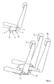
- FIG. 2 shows an embodiment of the vehicle seat according to the invention.
- both the front bearings 1 and the rear bearings 2 are each provided with a curved support 5. While one end of the carrier is respectively connected to the seat part, the other end is rotatably provided with the body of the vehicle. This pivot point is designated by the reference numeral 12.
- the two carriers 5 are preferably rotatably connected to one another by a connecting element 6, which engages in particular in the region of the curvature of the carrier 5.
- the connecting element extends substantially parallel to the side wall of the seat part.
- the skilled person understands that the same bearings and the connecting element are also provided on the other side of the seat. Overall, the storage in the present case therefore consists of six parts.
- the present embodiment of the vehicle seat according to the invention has the advantage that the vehicle seat is additionally lowered in its foremost position.
- the vehicle seat according to the invention is very simple and lightweight and the bearings and thus the adjustment length can be easily adapted to the existing space.
- In the longitudinal adjustment of the vehicle seat also performs a height adjustment, so that it can be used in particular as a child seat in its raised position, without a seat lift is needed.
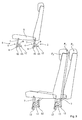
- FIG. 3 shows a further embodiment of the vehicle seat according to the invention, which in turn has two front bearings 1 and two rear bearings 2, which are all four identical in the present case.
- each bearing consists of three supports 7-9, so that the entire storage of the vehicle seat comprises twelve carriers.
- the carriers are each provided with each other and rotatable relative to the body 13 and the seat part S.
- each bearing has two pivot points 12 as a connection to the body 13.
- the gear 4 provided here, starting from position P 2, the offset to the front (position P 3 ) is less than the offset to the rear.
- the bearings 1 and 2 are identically constructed and also aligned identically.
- the vehicle seat according to the invention is very simple and lightweight and the bearings and thus the adjustment length can be easily adapted to the existing space.
- the adjustment length is comparatively large in this vehicle seat.
- the longitudinal adjustment takes place along a straight line and not along a curve.
- the three main positions can be recognized.
- the vehicle seat according to the invention is very simple and lightweight and the bearings and thus the adjustment length can be easily adapted to the existing space.
- the adjustment length is comparatively large in this vehicle seat.
- the longitudinal adjustment takes place along a straight line and not along a curve.
- a gear 4 is shown, which is used for both the front bearing 1 and the rear bearing 2.
- This transmission comprises in each case five carriers 7-11, the carrier 7 being rotatably provided with the seat part S and the carrier 8 being rotatable with the body. Otherwise, all connections between the carriers are provided with each other as a rotary connection.
- the carrier 11 is rotatably connected at one end to the carrier 9. At its other end it is mounted longitudinally displaceably in a guide 18, in the present case a slot guide. The slot guide is firmly connected to the body.
- the carrier 11 serves as a control to restrict the transmission in its degree of freedom.
- the seat according to the invention with the front bearings 1 and the rear bearings 2 is shown.
- the arrangement of the carriers and their connection is identical, wherein the carriers are each made longer in the front region, as in the bearings in the rear region 2.
- the vehicle seat according to the invention is very simple and lightweight and the bearings and thus the adjustment length can be easily adapted to the existing space.
- the adjustment length is comparatively large in this vehicle seat.
- the longitudinal adjustment takes place along a straight line and not along a curve.
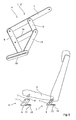
- FIG. 7 shows a further embodiment of the vehicle seat according to the invention.
- This telescoping support 14 has a telescoping part 17 which is fixedly connected to the pin 20 which is driven by the curve 16 of the base 19 during a rotational movement of the carrier 14 about the axis of rotation 22 and thereby the telescopic part 17 off or . retracts.
- End stops 21 are located in the edge region of the curve 16 in order to prevent the vehicle seat from being displaced beyond the positions P2, P3.
- the gears 4 of the front and rear bearings 1, 2 can be made identical or larger or smaller, however, always work on the same principle.
- the adjustment of the vehicle seat according to the invention with the transmission according to FIG. 7 is in FIG. 8 shown. Again, it can be seen clearly that starting from the position P1, the adjustment to the rear (position P2) is lower than the adjustment to the front. However, this depends on the design of the curve 16.
- the vehicle seat according to the invention is very simple and lightweight and the bearings and thus the adjustment length can be easily adapted to the existing space. The adjustment length is comparatively large in this vehicle seat. In the longitudinal adjustment takes place substantially along a straight line and not along a curve.
- FIG. 9 is essentially the vehicle seat according to FIG. 7 . 8th in the present case, only the curvature of the curve 16 provided on the pedestal 19 is different. In FIG. 9 the positions P1 and P2 are shown.
- FIG. 10 in turn shows a gear 4 with a telescoping carrier 14.
- the telescopic part 17 of the carrier 14 is at least partially formed as a rack, which is driven by the gear 15.
- the gear 15 is in turn driven by teeth 23 which are arranged on the base 19 when the carrier 14 rotates about the axis of rotation 22.
Landscapes
- Engineering & Computer Science (AREA)
- Aviation & Aerospace Engineering (AREA)
- Transportation (AREA)
- Mechanical Engineering (AREA)
- Seats For Vehicles (AREA)
Abstract
Description
- Die vorliegende Erfindung betrifft einen Fahrzeugsitz mit einem Sitzteil, das in seinem vorderen und in seinem hinteren Bereich mit jeweils zwei Lagern mit der Karosserie verbunden ist.
- Derartige Fahrzeugsitze sind aus dem Stand der Technik beispielsweise der
KR 10 013 1939 B1 FR 28 648 09 DE 10 2006 031 466 A1 , derDE 40 104 51 C2 , derDE 10 149 858 C2 , derGB 23 724 38 CA 26 710 03 , derWO 02/81870 A1 DE 42 409 43 A1 , sowie derDE 40 104 51 A1 bekannt. Die dort beschriebenen Fahrzeugsitze werden in der Regel als Fahrer oder Beifahrersitz eingesetzt. Für Fondsitze in Kraftfahrzeugen sind diese Verstellmechanismen jedoch zu aufwendig. - Es war deshalb die Aufgabe der vorliegenden Erfindung, einen verstellbaren Fahrzeugsitz, insbesondere für den Fondbereich zur Verfügung zu stellen.
- Gelöst wird die Aufgabe mit einem Fahrzeugsitz mit einem Sitzteil, das in seinem vorderen Bereich und in seinem hinteren Bereich mit jeweils zwei Lagern mit der Karosserie des Kraftfahrzeuges verbunden ist, wobei jedes Lager als gekrümmter Träger vorgesehen ist.
- Die für diesen Fahrzeugsitz gemachten Ausführungen gelten für die anderen erfindungsgemäßen Fahrzeugsitze gleichermaßen und umgekehrt.
- Die vorliegende Erfindung betrifft einen Fahrzeugsitz mit einem Sitzteil und einer Rückenlehne, an der vorzugsweise eine Kopfstütze vorgesehen ist. Der erfindungsgemäße Fahrzeugsitz kann einer oder mehreren Personen Platz bieten. Bei dem erfindungsgemäßen Fahrzeugsitz kann es sich folglich auch um eine Sitzbank handeln. Vorzugsweise wird der erfindungsgemäße Fahrzeugsitz im Fond, d. h. hinter der dem Fahrer und dem Beifahrersitz, angeordnet.
- Der erfindungsgemäße Fahrersitz ist sowohl in seinem vorderen Bereich, d. h. dem Bereich, in dem die Oberschenkel aufliegen, als auch in seinem hinteren Bereich, in dem die Rückenlehne angeordnet ist, mit jeweils zwei Lagern an der Karosserie des Fahrzeugs gelagert. Vorzugsweise sind diese Lager jeweils im rechten und im linken Bereich des Sitzteils vorgesehen.
- Erfindungsgemäß weist nun jedes dieser Lager einen gekrümmten Träger auf, wobei ein Ende dieses Trägers drehbar mit der Karosserie und das andere Ende drehbar mit dem Sitzteil und/oder drehbar mit einem weiteren Träger verbunden ist.
- Besonders bevorzugt ist der gekrümmte Träger des Lagers im vorderen Bereich mit dem dahinter liegenden gekrümmten Träger des hinteren Bereichs durch ein Verbindungselement, das im wesentlichen parallel zum Seitenteil des Sitzteils verläuft, miteinander verbunden. Vorzugsweise greift das Verbindungselement jeweils im Krümmungsbereich der Träger an.
- Ein weiterer Gegenstand der vorliegenden Erfindung ist ein Fahrzeugsitz mit einem Sitzteil, das in seinem vorderen Bereich und in seinem hinteren Bereich mit jeweils zwei Lagern mit der Karosserie des Kraftfahrzeuges verbunden ist, wobei jedes Lager als Getriebe vorgesehen ist, jedes Getriebe mindestens zwei Träger aufweist, die jeweils drehbar zueinander vorgesehen sind und die einzelnen Getriebe nicht miteinander verbunden sind. Jedes Lager ist sowohl drehbar mit der Karosserie als auch drehbar mit dem Sitzteil verbunden.
- Die zu diesem Fahrzeugsitz gemachten Ausführungen gelten für die anderen erfindungsgemäßen Fahrzeugsitze gleichermaßen und umgekehrt.
- Bei dem vorliegenden Fahrzeugsitz ist jedes Lager als Getriebe vorgesehen, wobei jedes Getriebe mindestens zwei Träger aufweist, die jeweils drehbar zueinander und drehbar relativ zu der Karosserie, bzw. dem Sitzteil des Fahrzeugsitzes vorgesehen sind. Erfindungsgemäß sind die einzelnen Getriebe nicht miteinander verbunden.
- Ein weiterer Gegenstand der vorliegenden Erfindung ist Fahrzeugsitz mit einem Sitzteil, das in seinem vorderen Bereich und in seinem hinteren Bereich mit jeweils zwei Lagern mit der Karosserie des Kraftfahrzeuges verbunden ist, wobei jedes Lager des Fahrzeugsitzes als Getriebe vorgesehen ist und jedes Getriebe einen teleskopierbaren Träger aufweist.
- Die zu diesem erfindungsgemäßen Gegenstand der vorliegenden Erfindung gemachten Ausführungen gelten für die anderen Gegenstände gleichermaßen und umgekehrt.
- Vorzugsweise wird der telekopierbare Teil des teleskopierbaren Trägers durch ein Antriebsmittel, insbesondere einer Kurve oder ein Zahnrad angetrieben, wobei der teleskopierbare Teil sowohl ein- als auch ausfahrbar ist.
- Die folgenden Ausführungen gelten für alle erfindungsgemäßen Gegenstände der vorliegenden Erfindung gleichermaßen.
- Vorzugsweise sind alle Getriebe funktionsidentisch aufgebaut, wobei besonders bevorzugt die Getriebe im vorderen, bzw. im hinteren Bereich identisch vorgesehen sind. Funktionsidentisch bedeutet, dass die Getriebe jeweils aus den gleichen Getriebemitteln aufgebaut sind, die jeweils in einem identischen Wirkzusammenhang zueinander vorgesehen sind, wobei sich jedoch die Länge der jeweiligen Getriebeteile unterscheiden kann.
- Weiterhin bevorzugt weist der Fahrzeugsitz ein Arretiermittel auf, mit dem er in der jeweiligen Position reversibel arretierbar ist.
- Vorzugsweise ist der Fahrzeugsitz in Längsrichtung und/oder in seiner Höhe verstellbar. Die Längsverstellung erfolgt insbesondere zu Komfortzwecken. Die Höhenverstellung kann zu Komfortzwecken aber auch aus Sicherheitsgründen, beispielsweise, wenn der erfindungsgemäße Fahrzeugsitz als Kindersitz eingesetzt wird, vorgesehen sein. Die Höhenverstellung kann ohne einen zusätzlichen Antrieb erfolgen. Sie erfolgt in einfacher Weise bei der Längsverstellung mit.
- Vorzugsweise ist an dem Fahrzeugsitz ein Mittel vorgesehen, dass die Verstellung des Sitzteils des erfindungsgemäßen Fahrzeugsitzes unterstütz und/oder in eine Position vorspannt. Beispielsweise handelt es sich bei dem Mittel um einen Kraftspeicher, insbesondere ein Federmittel.
- Es kann aber auch vorteilhaft sein, wenn der Fahrzeugsitz nur in Längsrichtung verschiebbar ist und bei dieser Verstellung seine Höhenposition nicht verändert.
- Ein weiterer Gegenstand der vorliegenden Erfindung ist deshalb ein Fahrzeugsitz, bei dem die Lager fest jedoch drehbar mit der Karosserie und dem Sitzteil verbunden sind und bei dem das Sitzteil in mindestens zwei Stellungen relativ zu der Karosserie einstellbar ist, wobei die Verstellung durch eine reine Translationsbewegung erfolgt. Bei dieser Ausführungsform erfolgt die Längsverstellung folglich ohne eine Höhenverstellung.
- Die zu diesem erfindungsgemäßen Gegenstand der vorliegenden Erfindung gemachten Ausführungen gelten für die anderen Gegenstände gleichermaßen und umgekehrt.
- Alle erfindungsgemäßen Fahrzeugsitze haben den Vorteil, dass eine Längsverstellung ohne Schienen im Fahrzeug erfolgen kann. Dadurch wird Gewicht eingespaart und durch die Schienen geht kein Raum verloren.
- Im Folgenden wird die Erfindung anhand der
Figuren 1 - 10 erläutert. Diese Erläuterungen sind lediglich beispielhaft und schränken den allgemeinen Erfindungsgedanken nicht ein. Die Ausführungen gelten für alle Gegenstände der vorliegenden Erfindung gleichermaßen. -
Figur 1 zeigt den prinzipiellen Aufbau des erfindungsgemäßen Fahrzeugsitzes. -
Figur 2 zeigt eine erste Ausführungsform des erfindungsgemäßen Fahrzeugsitzes. -
Figur 3 zeigt einen Fahrzeugsitz mit einem Getriebe als Lager. -
Figur 4 zeigt eine Abwandlung der Ausführung gemäßFigur 3 . -
Figuren 5 und6 zeigen eine weitere Ausführungsform eines Fahrzeugsitzes mit einem Getriebe. -
Figuren 7 und8 zeigen eine erste Ausführungsform eines Fahrzeugsitzes mit einem teleskopierbaren Träger. -
Figur 9 zeigt eine Abwandlung des Fahrzeugsitzes gemäßFigur 8 . -
Figur 10 zeigt eine weitere Ausführungsform eines Fahrzeugsitzes mit einem teleskopierbaren Träger. -
Figur 1 zeigt den prinzipiellen Aufbau des erfindungsgemäßen Fahrzeugsitzes F. Dieser weist ein Sitzteil S und eine Rückenlehne L auf. Das Sitzteil S ist mittels vier Lagern an der Fahrzeugkarosserie angeordnet, wobei zwei Lager 1 im vorderen Bereich und zwei Lager 2 im hinteren Bereich des Sitzteils angeordnet sind. Sowohl die vorderen Lager 1 als auch die hinteren Lager 2 befinden sich jeweils im rechten bzw. im linken Bereich, vorzugsweise im Randbereich, des Fahrzeugsitzes und sind identisch ausgeführt. Vorzugsweise sind die vorderen Lager 1 und die hinteren Lager 2 identisch vorgesehen. Die Lager 1, 2 sind mit einem Ende drehbar an der Karosserie und mit dem anderen Ende drehbar an dem Sitzteil angeordnet. Dadurch kann der gesamte Fahrzeugsitz, wie im unteren Teil vonFigur 1 dargestellt, zumindest in drei Hauptpositionen P1, P2 und P3 verbracht werden, indem die Lager 1, 2 um einen karosserieseitig vorgesehenen Drehpunkt gedreht werden. Der erfindungsgemäße Fahrzeugsitz weist ein Arretierungsmittel auf, mit dem der Fahrzeugsitz zumindest in den Hauptpositionen, vorzugweise jedoch auch zusätzlich in Nebenpositionen in seiner jeweiligen Lage sicherbar ist. In der Lage P1 befindet sich der Fahrzeugsitz in einer Mittelstellung und ist hier leicht erhöht. Diese Stellung ist insbesondere für Kinder, die eine erhöhte Sitzposition benötigen, vorteilhaft. Aus dieser Position P1 kann der Sitz im Uhrzeigersinn in die Position P2 verbracht werden, in der ein Sitzinsasse mehr Beinfreiheit hat. Desweiteren können die Lager 1, 2 gegen den Uhrzeigersinn verdreht werden, so dass der Fahrzeugsitz die Position P3 einnimmt, in der hinter dem Sitz zusätzlicher Raum für Beinfreiheit oder Lagerraum entsteht. -
Figur 2 zeigt eine erfindungsgemäße Ausführungsform des Fahrzeugsitzes. Im Wesentlichen kann auf die Ausführungen gemäßFigur 1 Bezug genommen werden, wobei in dem vorliegenden Fall sowohl die vorderen Lager 1 als auch die hinteren Lager 2 jeweils mit einem gekrümmten Träger 5 versehen sind. Während das eine Ende des Trägers jeweils mit dem Sitzteil verbunden ist, ist das andere Ende drehbar mit der Karosserie des Fahrzeuges vorgesehen. Dieser Drehpunkt ist mit dem Bezugszeichen 12 bezeichnet. Die beiden Träger 5 sind vorzugsweise durch ein Verbindungselement 6, das insbesondere jeweils im Bereich der Krümmung der Träger 5 angreift, miteinander drehbar verbunden. Das Verbindungselement erstreckt sich im Wesentlichen parallel zu der Seitenwand des Sitzteils. Der Fachmann versteht, dass dieselben Lager und das Verbindungselement auch auf der anderen Seite des Sitzes vorgesehen sind. Insgesamt besteht die Lagerung in dem vorliegenden Fall demnach aus sechs Teilen. In der unteren Darstellung vonFigur 2 sind wiederrum die drei Hauptpositionen des erfindungsgemäßen Fahrzeugsitzes P1 - P3 dargestellt. Die vorliegende Ausführungsform des erfindungsgemäßen Fahrzeugsitzes hat den Vorteil, dass der Fahrzeugsitz in seiner vordersten Stellung zusätzlich abgesenkt ist. Der erfindungsgemäße Fahrzeugsitz ist sehr einfach und leicht aufgebaut und die Lager und damit die Verstelllänge können in einfacher Weise an den vorhandenen Raum angepasst werden. Bei der Längsverstellung vollführt der Fahrzeugsitz auch eine Höhenverstellung, so dass er insbesondere in seiner angehobenen Stellung auch als Kindersitz einsetzbar ist, ohne dass eine Sitzerhöhung benötigt wird. -
Figur 3 zeigt eine weitere Ausführungsform des erfindungsgemäßen Fahrzeugsitzes, der wiederrum zwei vordere Lager 1 und zwei hintere Lager 2 aufweist, die in dem vorliegenden Fall alle vier identisch aufgebaut sind. In dem vorliegenden Fall besteht jedes Lager aus drei Trägern 7-9, so dass die gesamte Lagerung des Fahrzeugsitzes zwölf Träger umfasst. Die Träger sind jeweils untereinander sowie relativ zur Karosserie 13 bzw. zum Sitzteil S drehbar vorgesehen. In dem vorliegenden Fall weist jedes Lager zwei Drehpunkte 12 als Verbindung zur Karosserie 13 auf. Im unteren Teil derFigur 2 sind wiederrum die drei Hauptpositionen dargestellt. Es ist deutlich zu erkennen, dass bei dem hier vorgesehen Getriebe 4, ausgehend von Position P2 der Versatz nach vorne (Position P3) geringer ist, als der Versatz nach hinten. Der Fachmann erkennt, dass in dem vorliegenden Fall die Lager 1 und 2 identisch aufgebaut und auch identisch ausgerichtet sind. Der erfindungsgemäße Fahrzeugsitz ist sehr einfach und leicht aufgebaut und die Lager und damit die Verstelllänge können in einfacher Weise an den vorhandenen Raum angepasst werden. Die Verstelllänge ist bei diesem Fahrzeugsitz vergleichsweise groß. Die Längsverstellung erfolgt entlang einer Geraden und nicht entlang einer Kurve. - Dies ist bei der Ausführungsform gemäß
Figur 4 werden dieselben Lager wie bei dem Beispiel gemäßFigur 3 verwandt, wobei in dem vorliegenden Fall die beiden Getriebe 4 der Lager 1, 2 jeweils spiegelsymmetrisch angeordnet sind. Im unteren Teil derFigur 4 sind wiederrum die drei Hauptpositionen zu erkennen. Der erfindungsgemäße Fahrzeugsitz ist sehr einfach und leicht aufgebaut und die Lager und damit die Verstelllänge können in einfacher Weise an den vorhandenen Raum angepasst werden. Die Verstelllänge ist bei diesem Fahrzeugsitz vergleichsweise groß. Die Längsverstellung erfolgt entlang einer Geraden und nicht entlang einer Kurve. - In
Figur 5 ist ein Getriebe 4 dargestellt, das sowohl für das vordere Lager 1 als auch für das hintere Lager 2 eingesetzt wird. Dieses Getriebe umfasst jeweils fünf Träger 7-11, wobei der Träger 7 drehbar mit dem Sitzteil S und der Träger 8 drehbar mit der Karosserie vorgesehen ist. Ansonsten sind alle Verbindungen zwischen den Trägern untereinander als Drehverbindung vorgesehen. Der Träger 11 ist an seinem einen Ende drehbar mit dem Träger 9 verbunden. An seinem anderen Ende wird er in einer Führung 18, in dem vorliegenden Fall einer Schlitzführung längsverschieblich gelagert. Die Schlitzführung ist fest mit der Karosserie verbunden. Der Träger 11 dient als Steuerelement, um das Getriebe in seinem Freiheitsgrad einzuschränken. Im unteren Teil derFigur 5 ist der erfindungsgemäße Sitz mit den vorderen Lagern 1 und den hinteren Lagern 2 dargestellt. Es ist deutlich zu erkennen, dass die Anordnung der Träger und deren Verbindung identisch ist, wobei die Träger in dem vorderen Bereich jeweils länger ausgeführt sind, als bei den Lagern im hinteren Bereich 2. Dadurch macht das Sitzteil, wie inFigur 6 zu erkennen ist, bei seiner Bewegung von der Stellung P2 in P3 eine Kippbewegung im Uhrzeigersinn. Der erfindungsgemäße Fahrzeugsitz ist sehr einfach und leicht aufgebaut und die Lager und damit die Verstelllänge können in einfacher Weise an den vorhandenen Raum angepasst werden. Die Verstelllänge ist bei diesem Fahrzeugsitz vergleichsweise groß. Die Längsverstellung erfolgt entlang einer Geraden und nicht entlang einer Kurve. -
Figur 7 zeigt eine weitere Ausführungsform des erfindungsgemäßen Fahrzeugsitzes. In dem vorliegenden Fall weist das Getriebe 4 des vorderen und des hinteren Lagers 1, 2 einen teleskopierbaren Träger 14 auf. Dieser teleskopierbare Träger 14 weist einen teleskopierbaren Teil 17 auf, der fest mit dem Pin 20 verbunden ist, der bei einer Drehbewegung des Trägers 14 um die Drehachse 22 von der Kurve 16 des Sockels 19 angetrieben wird und dabei den teleskopierbaren Teil 17 aus-, bzw. einfährt. Im Randbereich der Kurve 16 befinden sich jeweils Endanschläge 21, um zu verhindern, dass der Fahrzeugsitz über die Positionen P2, P3 hinaus verstellt wird. Die Getriebe 4 des vorderen und des hinteren Lagers 1, 2 können identisch oder größer oder kleiner ausgeführt werden, funktionieren jedoch immer nach demselben Prinzip. Die Verstellung des erfindungsgemäßen Fahrzeugsitzes mit dem Getriebe gemäßFigur 7 ist inFigur 8 dargestellt. Auch hier ist deutlich zu erkennen, dass ausgehend von der Position P1 die Verstellung nach hinten (Position P2) geringer ist, als die Verstellung nach vorne. Dies hängt jedoch von der Gestaltung der Kurve 16 ab. Der erfindungsgemäße Fahrzeugsitz ist sehr einfach und leicht aufgebaut und die Lager und damit die Verstelllänge können in einfacher Weise an den vorhandenen Raum angepasst werden. Die Verstelllänge ist bei diesem Fahrzeugsitz vergleichsweise groß. Bei der Längsverstellung erfolgt im wesentlichen entlang einer Geraden und nicht entlang einer Kurve. - In
Figur 9 ist im Wesentlichen der Fahrzeugsitz gemäßFigur 7 ,8 dargestellt, wobei in dem vorliegenden Fall lediglich die Krümmung der Kurve 16, die an dem Sockel 19 vorgesehen ist, unterschiedlich ist. InFigur 9 sind die Positionen P1 und P2 dargestellt. -
Figur 10 zeigt wiederrum ein Getriebe 4 mit einem teleskopierbaren Träger 14. In dem vorliegenden Fall ist der teleskopierbare Teil 17 des Trägers 14 zumindest teilweise als Zahnstange ausgebildet, die von dem Zahnrad 15 angetrieben wird. Das Zahnrad 15 wird wiederrum durch Zähne 23, die an dem Sockel 19 angeordnet sind, angetrieben, wenn der Träger 14 um die Drehachse 22 rotiert. -
- 1
- vorderes Lager
- 2
- hinteres Lager
- 3
- Karosserie
- 4
- Getriebe
- 5
- gekrümmter Träger
- 6
- Verbindungselement
- 7-11
- Träger
- 12
- Verbindung mit der Karosserie
- 13
- Karosserie
- 14
- teleskopierbarer Träger
- 15
- Zahnrad
- 16
- Kurve
- 17
- teleskopierbarer Teil
- 18
- Führung
- 19
- Sockel
- 20
- Pin
- 21
- Endanschlag
- 22
- Drehachse
- 23
- Zahnkurve
- F
- Fahrzeugsitz
- L
- Lehne
- P1,2,3
- Position
- S
- Sitzteil
Claims (9)
- Fahrzeugsitz (F) mit einem Sitzteil (S), das in seinem vorderen Bereich und in seinem hinteren Bereich mit jeweils zwei Lagern (1, 2) mit der Karosserie (3) verbunden ist, dadurch gekennzeichnet, dass jedes Lager als gekrümmter Träger (5) vorgesehen ist.
- Fahrzeugsitz (F) nach Anspruch 1, dadurch gekennzeichnet, dass jeweils zwei gekrümmte Träger mit einem Verbindungselement (6) miteinander verbunden sind.
- Fahrzeugsitz (F) nach dem Oberbegriff von Anspruch 1, dadurch gekennzeichnet, dass jedes Lager (1, 2) als Getriebe (4) vorgesehen ist, jedes Getriebe (4) mindestens zwei Träger (7 - 11) aufweist, die jeweils drehbar zueinander vorgesehen sind und die einzelnen Getriebe nicht miteinander verbunden sind.
- Fahrzeugsitz (F) nach dem Oberbegriff von Anspruch 1, dadurch gekennzeichnet, dass jedes Lager (1, 2) als Getriebe (4) vorgesehen ist und dass jedes Getriebe (4) einen teleskopierbaren Träger (14) aufweist.
- Fahrzeugsitz (F) nach Anspruch 4, dadurch gekennzeichnet, dass der teleskopierbare Teil (17) durch ein Antriebsmittel (15, 16, 20), insbesondere eine Kurve (16) oder ein Zahnrad (15) angetrieben wird.
- Fahrzeugsitz (F) nach einem der voranstehenden Ansprüche, dadurch gekennzeichnet, dass er als Kindersitz vorsehbar ist.
- Fahrzeugsitz (F) nach dem Oberbegriff von Patentanspruch 1 oder einem der voranstehenden Ansprüche, dadurch gekennzeichnet, dass die Lager fest jedoch drehbar mit der Karosserie und dem Sitzteil verbunden sind und das Sitzteil in mindestens zwei Stellungen relativ zu der Karosserie (3) einstellbar ist, wobei die Verstellung durch eine reine Translationsbewegung erfolgt.
- Fahrzeugsitz nach einem der voranstehenden Ansprüche, dadurch gekennzeichnet, dass alle Getriebe (4) funktionsidentisch aufgebaut sind.
- Fahrzeugsitz (F) nach einem der voranstehenden Ansprüche, dadurch gekennzeichnet, dass er ein Arretiermittel aufweist.
Applications Claiming Priority (2)
| Application Number | Priority Date | Filing Date | Title |
|---|---|---|---|
| DE102010007951 | 2010-02-12 | ||
| DE102010049365A DE102010049365A1 (de) | 2010-02-12 | 2010-10-26 | Fahrzeugsitz mit einem Sitzversteller |
Publications (3)
| Publication Number | Publication Date |
|---|---|
| EP2360051A2 true EP2360051A2 (de) | 2011-08-24 |
| EP2360051A3 EP2360051A3 (de) | 2014-07-23 |
| EP2360051B1 EP2360051B1 (de) | 2017-08-23 |
Family
ID=44168785
Family Applications (1)
| Application Number | Title | Priority Date | Filing Date |
|---|---|---|---|
| EP11000733.3A Not-in-force EP2360051B1 (de) | 2010-02-12 | 2011-01-31 | Fahrzeugsitz mit einem Sitzversteller |
Country Status (2)
| Country | Link |
|---|---|
| EP (1) | EP2360051B1 (de) |
| DE (1) | DE102010049365A1 (de) |
Cited By (5)
| Publication number | Priority date | Publication date | Assignee | Title |
|---|---|---|---|---|
| WO2018215569A1 (de) * | 2017-05-23 | 2018-11-29 | Bayerische Motoren Werke Aktiengesellschaft | Fahrzeugsitz |
| DE102019129162A1 (de) * | 2019-10-29 | 2021-04-29 | Grammer Aktiengesellschaft | Vorrichtung zur Einstellung einer Sitzposition |
| US11433789B2 (en) | 2019-10-29 | 2022-09-06 | Grammer Ag | Device for adjusting a seat position |
| US11679697B2 (en) | 2019-10-29 | 2023-06-20 | Grammer Ag | Device for adjusting a seat position |
| DE102023003114A1 (de) | 2023-07-28 | 2025-01-30 | Mercedes-Benz Group AG | Fahrzeugsitz sowie Verfahren |
Families Citing this family (1)
| Publication number | Priority date | Publication date | Assignee | Title |
|---|---|---|---|---|
| DE102020119358B4 (de) | 2020-07-22 | 2023-01-19 | Audi Aktiengesellschaft | Anordnung für einen Fahrzeugsitz |
Citations (9)
| Publication number | Priority date | Publication date | Assignee | Title |
|---|---|---|---|---|
| DE4010451A1 (de) | 1990-03-31 | 1991-10-02 | Audi Ag | Sitz fuer kraftfahrzeuge |
| DE4240943A1 (de) | 1992-11-14 | 1994-05-19 | Hammerstein Gmbh C Rob | Arretiervorrichtung für eine Längsverstellvorrichtung eines Fahrzeugsitzes mit einem Sitzträger, an dem seitlich ein Betätigungshebel der Arretiervorrichtung angelenkt ist |
| KR0131939B1 (ko) | 1994-12-28 | 1998-04-21 | 전성원 | 상하 및 좌우 위치조정이 동시에 가능한 시트용 링크 |
| GB2372438A (en) | 2001-02-23 | 2002-08-28 | Johnson Controls Tech Co | Vehicle seat mechanism, seat cushion folds up vertically as seat back moves horizontally backwards and vertically downwards during stowage |
| WO2002081870A1 (de) | 2001-04-06 | 2002-10-17 | Alstom (Switzerland) Ltd | Verfahren zur bereitschaftshaltung eines kombikraftwerkes |
| DE10149858C2 (de) | 2001-10-10 | 2003-10-02 | Johnson Controls Gmbh | Fahrzeugsitz mit schwenkbarer Rückenlehne |
| FR2864809A1 (fr) | 2004-01-07 | 2005-07-08 | Volkswagen Ag | Siege rabattable a plat |
| DE102006031466A1 (de) | 2005-09-08 | 2007-03-29 | Bayerische Motoren Werke Ag | Sitz für ein Kraftfahrzeug |
| CA2671003A1 (en) | 2007-01-16 | 2008-07-24 | Intier Automotive Inc. | Stand up and kneel seat |
Family Cites Families (3)
| Publication number | Priority date | Publication date | Assignee | Title |
|---|---|---|---|---|
| GB734969A (en) * | 1953-04-11 | 1955-08-10 | Hallam Sleigh & Cheston Ltd | Improvements in adjustable seats |
| IT1223651B (it) * | 1988-07-01 | 1990-09-29 | Fiat Auto Spa | Sedile per veicoli particolarmente autovetture |
| DE19716596C2 (de) * | 1997-04-21 | 1999-10-28 | Faure Bertrand Sitztech Gmbh | Sitzteil für einen Kraftfahrzeugsitz |
-
2010
- 2010-10-26 DE DE102010049365A patent/DE102010049365A1/de not_active Ceased
-
2011
- 2011-01-31 EP EP11000733.3A patent/EP2360051B1/de not_active Not-in-force
Patent Citations (10)
| Publication number | Priority date | Publication date | Assignee | Title |
|---|---|---|---|---|
| DE4010451A1 (de) | 1990-03-31 | 1991-10-02 | Audi Ag | Sitz fuer kraftfahrzeuge |
| DE4010451C2 (de) | 1990-03-31 | 1998-07-23 | Audi Ag | Sitz für Kraftfahrzeuge |
| DE4240943A1 (de) | 1992-11-14 | 1994-05-19 | Hammerstein Gmbh C Rob | Arretiervorrichtung für eine Längsverstellvorrichtung eines Fahrzeugsitzes mit einem Sitzträger, an dem seitlich ein Betätigungshebel der Arretiervorrichtung angelenkt ist |
| KR0131939B1 (ko) | 1994-12-28 | 1998-04-21 | 전성원 | 상하 및 좌우 위치조정이 동시에 가능한 시트용 링크 |
| GB2372438A (en) | 2001-02-23 | 2002-08-28 | Johnson Controls Tech Co | Vehicle seat mechanism, seat cushion folds up vertically as seat back moves horizontally backwards and vertically downwards during stowage |
| WO2002081870A1 (de) | 2001-04-06 | 2002-10-17 | Alstom (Switzerland) Ltd | Verfahren zur bereitschaftshaltung eines kombikraftwerkes |
| DE10149858C2 (de) | 2001-10-10 | 2003-10-02 | Johnson Controls Gmbh | Fahrzeugsitz mit schwenkbarer Rückenlehne |
| FR2864809A1 (fr) | 2004-01-07 | 2005-07-08 | Volkswagen Ag | Siege rabattable a plat |
| DE102006031466A1 (de) | 2005-09-08 | 2007-03-29 | Bayerische Motoren Werke Ag | Sitz für ein Kraftfahrzeug |
| CA2671003A1 (en) | 2007-01-16 | 2008-07-24 | Intier Automotive Inc. | Stand up and kneel seat |
Cited By (8)
| Publication number | Priority date | Publication date | Assignee | Title |
|---|---|---|---|---|
| WO2018215569A1 (de) * | 2017-05-23 | 2018-11-29 | Bayerische Motoren Werke Aktiengesellschaft | Fahrzeugsitz |
| DE102019129162A1 (de) * | 2019-10-29 | 2021-04-29 | Grammer Aktiengesellschaft | Vorrichtung zur Einstellung einer Sitzposition |
| US11433789B2 (en) | 2019-10-29 | 2022-09-06 | Grammer Ag | Device for adjusting a seat position |
| US11654799B2 (en) | 2019-10-29 | 2023-05-23 | Grammer Ag | Apparatus for adjusting a seat position |
| US11679697B2 (en) | 2019-10-29 | 2023-06-20 | Grammer Ag | Device for adjusting a seat position |
| DE102019129162B4 (de) | 2019-10-29 | 2023-11-02 | Grammer Aktiengesellschaft | Vorrichtung zur Einstellung einer Sitzposition und Fahrzeugsitz |
| DE102023003114A1 (de) | 2023-07-28 | 2025-01-30 | Mercedes-Benz Group AG | Fahrzeugsitz sowie Verfahren |
| DE102023003114B4 (de) | 2023-07-28 | 2025-05-15 | Mercedes-Benz Group AG | Fahrzeugsitz sowie Verfahren |
Also Published As
| Publication number | Publication date |
|---|---|
| EP2360051A3 (de) | 2014-07-23 |
| DE102010049365A1 (de) | 2011-08-18 |
| EP2360051B1 (de) | 2017-08-23 |
Similar Documents
| Publication | Publication Date | Title |
|---|---|---|
| DE102017218492B4 (de) | Längseinsteller und fahrzeugsitz | |
| DE102012112529B3 (de) | Nutzfahrzeugsitz mit einem Verriegelungselement | |
| DE102008046000B4 (de) | Sitztiefenverstellbarer Fahrzeugsitz mit einem ersten Sitzteil und einem zweiten Sitzteil | |
| DE102009053537B4 (de) | Schwenkbare Armlehne zur Verwendung in einem Fahrzeug | |
| EP2337704B1 (de) | Untergestell eines kraftfahrzeugsitzes mit zwei schienenpaaren, schwingen und einem sitzträger | |
| DE69503180T2 (de) | Sitz mit veränderlichem Raumbedarf, insbesondere für Flugzeuge | |
| DE102013227013B4 (de) | Sitzvorrichtung, Fahrgastraum, Fahrzeug | |
| EP2360051B1 (de) | Fahrzeugsitz mit einem Sitzversteller | |
| DE102020100183A1 (de) | Fahrzeugsitzbaugruppe | |
| DE102014209168B4 (de) | Fahrzeugsitz | |
| DE102015013362B4 (de) | Kopfstütze für einen Fahrzeugsitz | |
| DE102016204067A1 (de) | Vorrichtung zum Verstellen zumindest einer Seitenwange eines Sitzteils und/oder einer Rückenlehne eines Fahrzeugsitzes | |
| DE102009033494A1 (de) | Fahrzeugsitz | |
| DE102009008500A1 (de) | Schienenpaar für einen längseinstellbaren Fahrzeugsitz | |
| DE102013225123B4 (de) | Fahrzeugsitz mit einer Höhenverstell- und Schwenkvorrichtung | |
| DE102010044448B4 (de) | In X-Richtung verstellbare Kopfstütze und Arretierungssystem | |
| DE102009010689B4 (de) | Höhenverstellung mit einem mehrteilig ausgeführten Abtriebsmittel | |
| WO2008014876A1 (de) | Faltbarer kraftfahrzeugsitz | |
| DE102017212345A1 (de) | Bewegliche Stützstruktur für einen Fahrzeugsitz | |
| DE102014213104A1 (de) | Längseinsteller für einen fahrzeugsitz und fahrzeugsitz | |
| DE4038279C2 (de) | Kraftfahrzeugsitz mit wenigstens einer Schenkelstütze | |
| DE102018207036B4 (de) | Höhenverstellbare Armlehne mit motorisierter Antriebseinrichtung und Kraftfahrzeug mit einer solchen Armlehne | |
| DE102016015269A1 (de) | Fahrzeugsitz | |
| DE2529556A1 (de) | Vorrichtung zur einstellung eines fahrzeugsitzes | |
| DE102019108663A1 (de) | Kraftfahrzeugsitz |
Legal Events
| Date | Code | Title | Description |
|---|---|---|---|
| PUAI | Public reference made under article 153(3) epc to a published international application that has entered the european phase |
Free format text: ORIGINAL CODE: 0009012 |
|
| AK | Designated contracting states |
Kind code of ref document: A2 Designated state(s): AL AT BE BG CH CY CZ DE DK EE ES FI FR GB GR HR HU IE IS IT LI LT LU LV MC MK MT NL NO PL PT RO RS SE SI SK SM TR |
|
| AX | Request for extension of the european patent |
Extension state: BA ME |
|
| RIC1 | Information provided on ipc code assigned before grant |
Ipc: B60N 2/16 20060101AFI20140227BHEP Ipc: B60N 2/50 20060101ALI20140227BHEP Ipc: B60N 2/18 20060101ALI20140227BHEP Ipc: B60N 2/04 20060101ALI20140227BHEP |
|
| PUAL | Search report despatched |
Free format text: ORIGINAL CODE: 0009013 |
|
| AK | Designated contracting states |
Kind code of ref document: A3 Designated state(s): AL AT BE BG CH CY CZ DE DK EE ES FI FR GB GR HR HU IE IS IT LI LT LU LV MC MK MT NL NO PL PT RO RS SE SI SK SM TR |
|
| AX | Request for extension of the european patent |
Extension state: BA ME |
|
| RIC1 | Information provided on ipc code assigned before grant |
Ipc: B60N 2/16 20060101AFI20140617BHEP Ipc: B60N 2/04 20060101ALI20140617BHEP Ipc: B60N 2/18 20060101ALI20140617BHEP Ipc: B60N 2/50 20060101ALI20140617BHEP |
|
| 17P | Request for examination filed |
Effective date: 20150123 |
|
| RBV | Designated contracting states (corrected) |
Designated state(s): AL AT BE BG CH CY CZ DE DK EE ES FI FR GB GR HR HU IE IS IT LI LT LU LV MC MK MT NL NO PL PT RO RS SE SI SK SM TR |
|
| GRAP | Despatch of communication of intention to grant a patent |
Free format text: ORIGINAL CODE: EPIDOSNIGR1 |
|
| INTG | Intention to grant announced |
Effective date: 20170406 |
|
| RAP1 | Party data changed (applicant data changed or rights of an application transferred) |
Owner name: ADIENT LUXEMBOURG HOLDING S.A R.L. |
|
| GRAS | Grant fee paid |
Free format text: ORIGINAL CODE: EPIDOSNIGR3 |
|
| GRAA | (expected) grant |
Free format text: ORIGINAL CODE: 0009210 |
|
| AK | Designated contracting states |
Kind code of ref document: B1 Designated state(s): AL AT BE BG CH CY CZ DE DK EE ES FI FR GB GR HR HU IE IS IT LI LT LU LV MC MK MT NL NO PL PT RO RS SE SI SK SM TR |
|
| REG | Reference to a national code |
Ref country code: GB Ref legal event code: FG4D Free format text: NOT ENGLISH |
|
| REG | Reference to a national code |
Ref country code: CH Ref legal event code: EP |
|
| REG | Reference to a national code |
Ref country code: AT Ref legal event code: REF Ref document number: 920939 Country of ref document: AT Kind code of ref document: T Effective date: 20170915 |
|
| REG | Reference to a national code |
Ref country code: IE Ref legal event code: FG4D Free format text: LANGUAGE OF EP DOCUMENT: GERMAN |
|
| REG | Reference to a national code |
Ref country code: DE Ref legal event code: R096 Ref document number: 502011012829 Country of ref document: DE |
|
| REG | Reference to a national code |
Ref country code: NL Ref legal event code: MP Effective date: 20170823 |
|
| REG | Reference to a national code |
Ref country code: LT Ref legal event code: MG4D |
|
| REG | Reference to a national code |
Ref country code: FR Ref legal event code: PLFP Year of fee payment: 8 |
|
| PG25 | Lapsed in a contracting state [announced via postgrant information from national office to epo] |
Ref country code: FI Free format text: LAPSE BECAUSE OF FAILURE TO SUBMIT A TRANSLATION OF THE DESCRIPTION OR TO PAY THE FEE WITHIN THE PRESCRIBED TIME-LIMIT Effective date: 20170823 Ref country code: NL Free format text: LAPSE BECAUSE OF FAILURE TO SUBMIT A TRANSLATION OF THE DESCRIPTION OR TO PAY THE FEE WITHIN THE PRESCRIBED TIME-LIMIT Effective date: 20170823 Ref country code: SE Free format text: LAPSE BECAUSE OF FAILURE TO SUBMIT A TRANSLATION OF THE DESCRIPTION OR TO PAY THE FEE WITHIN THE PRESCRIBED TIME-LIMIT Effective date: 20170823 Ref country code: HR Free format text: LAPSE BECAUSE OF FAILURE TO SUBMIT A TRANSLATION OF THE DESCRIPTION OR TO PAY THE FEE WITHIN THE PRESCRIBED TIME-LIMIT Effective date: 20170823 Ref country code: LT Free format text: LAPSE BECAUSE OF FAILURE TO SUBMIT A TRANSLATION OF THE DESCRIPTION OR TO PAY THE FEE WITHIN THE PRESCRIBED TIME-LIMIT Effective date: 20170823 Ref country code: NO Free format text: LAPSE BECAUSE OF FAILURE TO SUBMIT A TRANSLATION OF THE DESCRIPTION OR TO PAY THE FEE WITHIN THE PRESCRIBED TIME-LIMIT Effective date: 20171123 |
|
| PG25 | Lapsed in a contracting state [announced via postgrant information from national office to epo] |
Ref country code: LV Free format text: LAPSE BECAUSE OF FAILURE TO SUBMIT A TRANSLATION OF THE DESCRIPTION OR TO PAY THE FEE WITHIN THE PRESCRIBED TIME-LIMIT Effective date: 20170823 Ref country code: PL Free format text: LAPSE BECAUSE OF FAILURE TO SUBMIT A TRANSLATION OF THE DESCRIPTION OR TO PAY THE FEE WITHIN THE PRESCRIBED TIME-LIMIT Effective date: 20170823 Ref country code: RS Free format text: LAPSE BECAUSE OF FAILURE TO SUBMIT A TRANSLATION OF THE DESCRIPTION OR TO PAY THE FEE WITHIN THE PRESCRIBED TIME-LIMIT Effective date: 20170823 Ref country code: ES Free format text: LAPSE BECAUSE OF FAILURE TO SUBMIT A TRANSLATION OF THE DESCRIPTION OR TO PAY THE FEE WITHIN THE PRESCRIBED TIME-LIMIT Effective date: 20170823 Ref country code: BG Free format text: LAPSE BECAUSE OF FAILURE TO SUBMIT A TRANSLATION OF THE DESCRIPTION OR TO PAY THE FEE WITHIN THE PRESCRIBED TIME-LIMIT Effective date: 20171123 Ref country code: GR Free format text: LAPSE BECAUSE OF FAILURE TO SUBMIT A TRANSLATION OF THE DESCRIPTION OR TO PAY THE FEE WITHIN THE PRESCRIBED TIME-LIMIT Effective date: 20171124 Ref country code: IS Free format text: LAPSE BECAUSE OF FAILURE TO SUBMIT A TRANSLATION OF THE DESCRIPTION OR TO PAY THE FEE WITHIN THE PRESCRIBED TIME-LIMIT Effective date: 20171223 |
|
| REG | Reference to a national code |
Ref country code: DE Ref legal event code: R081 Ref document number: 502011012829 Country of ref document: DE Owner name: ADIENT US LLC, PLYMOUTH, US Free format text: FORMER OWNER: ADIENT LUXEMBOURG HOLDING S.A.R.L., LUXEMBOURG, LU Ref country code: DE Ref legal event code: R081 Ref document number: 502011012829 Country of ref document: DE Owner name: ADIENT LUXEMBOURG HOLDING S.A R.L., LU Free format text: FORMER OWNER: ADIENT LUXEMBOURG HOLDING S.A.R.L., LUXEMBOURG, LU |
|
| RAP2 | Party data changed (patent owner data changed or rights of a patent transferred) |
Owner name: ADIENT LUXEMBOURG HOLDING S.A R.L. |
|
| PG25 | Lapsed in a contracting state [announced via postgrant information from national office to epo] |
Ref country code: DK Free format text: LAPSE BECAUSE OF FAILURE TO SUBMIT A TRANSLATION OF THE DESCRIPTION OR TO PAY THE FEE WITHIN THE PRESCRIBED TIME-LIMIT Effective date: 20170823 Ref country code: RO Free format text: LAPSE BECAUSE OF FAILURE TO SUBMIT A TRANSLATION OF THE DESCRIPTION OR TO PAY THE FEE WITHIN THE PRESCRIBED TIME-LIMIT Effective date: 20170823 Ref country code: CZ Free format text: LAPSE BECAUSE OF FAILURE TO SUBMIT A TRANSLATION OF THE DESCRIPTION OR TO PAY THE FEE WITHIN THE PRESCRIBED TIME-LIMIT Effective date: 20170823 |
|
| REG | Reference to a national code |
Ref country code: DE Ref legal event code: R097 Ref document number: 502011012829 Country of ref document: DE |
|
| PG25 | Lapsed in a contracting state [announced via postgrant information from national office to epo] |
Ref country code: SK Free format text: LAPSE BECAUSE OF FAILURE TO SUBMIT A TRANSLATION OF THE DESCRIPTION OR TO PAY THE FEE WITHIN THE PRESCRIBED TIME-LIMIT Effective date: 20170823 Ref country code: EE Free format text: LAPSE BECAUSE OF FAILURE TO SUBMIT A TRANSLATION OF THE DESCRIPTION OR TO PAY THE FEE WITHIN THE PRESCRIBED TIME-LIMIT Effective date: 20170823 Ref country code: IT Free format text: LAPSE BECAUSE OF FAILURE TO SUBMIT A TRANSLATION OF THE DESCRIPTION OR TO PAY THE FEE WITHIN THE PRESCRIBED TIME-LIMIT Effective date: 20170823 Ref country code: SM Free format text: LAPSE BECAUSE OF FAILURE TO SUBMIT A TRANSLATION OF THE DESCRIPTION OR TO PAY THE FEE WITHIN THE PRESCRIBED TIME-LIMIT Effective date: 20170823 |
|
| PLBE | No opposition filed within time limit |
Free format text: ORIGINAL CODE: 0009261 |
|
| STAA | Information on the status of an ep patent application or granted ep patent |
Free format text: STATUS: NO OPPOSITION FILED WITHIN TIME LIMIT |
|
| 26N | No opposition filed |
Effective date: 20180524 |
|
| PG25 | Lapsed in a contracting state [announced via postgrant information from national office to epo] |
Ref country code: SI Free format text: LAPSE BECAUSE OF FAILURE TO SUBMIT A TRANSLATION OF THE DESCRIPTION OR TO PAY THE FEE WITHIN THE PRESCRIBED TIME-LIMIT Effective date: 20170823 |
|
| REG | Reference to a national code |
Ref country code: CH Ref legal event code: PL |
|
| GBPC | Gb: european patent ceased through non-payment of renewal fee |
Effective date: 20180131 |
|
| PG25 | Lapsed in a contracting state [announced via postgrant information from national office to epo] |
Ref country code: MT Free format text: LAPSE BECAUSE OF FAILURE TO SUBMIT A TRANSLATION OF THE DESCRIPTION OR TO PAY THE FEE WITHIN THE PRESCRIBED TIME-LIMIT Effective date: 20170823 |
|
| PG25 | Lapsed in a contracting state [announced via postgrant information from national office to epo] |
Ref country code: LU Free format text: LAPSE BECAUSE OF NON-PAYMENT OF DUE FEES Effective date: 20180131 |
|
| REG | Reference to a national code |
Ref country code: IE Ref legal event code: MM4A |
|
| REG | Reference to a national code |
Ref country code: BE Ref legal event code: MM Effective date: 20180131 |
|
| PG25 | Lapsed in a contracting state [announced via postgrant information from national office to epo] |
Ref country code: GB Free format text: LAPSE BECAUSE OF NON-PAYMENT OF DUE FEES Effective date: 20180131 Ref country code: BE Free format text: LAPSE BECAUSE OF NON-PAYMENT OF DUE FEES Effective date: 20180131 Ref country code: LI Free format text: LAPSE BECAUSE OF NON-PAYMENT OF DUE FEES Effective date: 20180131 Ref country code: CH Free format text: LAPSE BECAUSE OF NON-PAYMENT OF DUE FEES Effective date: 20180131 |
|
| PG25 | Lapsed in a contracting state [announced via postgrant information from national office to epo] |
Ref country code: IE Free format text: LAPSE BECAUSE OF NON-PAYMENT OF DUE FEES Effective date: 20180131 |
|
| REG | Reference to a national code |
Ref country code: AT Ref legal event code: MM01 Ref document number: 920939 Country of ref document: AT Kind code of ref document: T Effective date: 20180131 |
|
| PG25 | Lapsed in a contracting state [announced via postgrant information from national office to epo] |
Ref country code: AT Free format text: LAPSE BECAUSE OF NON-PAYMENT OF DUE FEES Effective date: 20180131 |
|
| PG25 | Lapsed in a contracting state [announced via postgrant information from national office to epo] |
Ref country code: MC Free format text: LAPSE BECAUSE OF FAILURE TO SUBMIT A TRANSLATION OF THE DESCRIPTION OR TO PAY THE FEE WITHIN THE PRESCRIBED TIME-LIMIT Effective date: 20170823 |
|
| PG25 | Lapsed in a contracting state [announced via postgrant information from national office to epo] |
Ref country code: TR Free format text: LAPSE BECAUSE OF FAILURE TO SUBMIT A TRANSLATION OF THE DESCRIPTION OR TO PAY THE FEE WITHIN THE PRESCRIBED TIME-LIMIT Effective date: 20170823 |
|
| PG25 | Lapsed in a contracting state [announced via postgrant information from national office to epo] |
Ref country code: HU Free format text: LAPSE BECAUSE OF FAILURE TO SUBMIT A TRANSLATION OF THE DESCRIPTION OR TO PAY THE FEE WITHIN THE PRESCRIBED TIME-LIMIT; INVALID AB INITIO Effective date: 20110131 Ref country code: PT Free format text: LAPSE BECAUSE OF FAILURE TO SUBMIT A TRANSLATION OF THE DESCRIPTION OR TO PAY THE FEE WITHIN THE PRESCRIBED TIME-LIMIT Effective date: 20170823 |
|
| PG25 | Lapsed in a contracting state [announced via postgrant information from national office to epo] |
Ref country code: MK Free format text: LAPSE BECAUSE OF NON-PAYMENT OF DUE FEES Effective date: 20170823 Ref country code: CY Free format text: LAPSE BECAUSE OF FAILURE TO SUBMIT A TRANSLATION OF THE DESCRIPTION OR TO PAY THE FEE WITHIN THE PRESCRIBED TIME-LIMIT Effective date: 20170823 |
|
| PG25 | Lapsed in a contracting state [announced via postgrant information from national office to epo] |
Ref country code: AL Free format text: LAPSE BECAUSE OF FAILURE TO SUBMIT A TRANSLATION OF THE DESCRIPTION OR TO PAY THE FEE WITHIN THE PRESCRIBED TIME-LIMIT Effective date: 20170823 |
|
| REG | Reference to a national code |
Ref country code: DE Ref legal event code: R082 Ref document number: 502011012829 Country of ref document: DE Representative=s name: LIEDHEGENER, RALF, DIPL.-ING., DE |
|
| PGFP | Annual fee paid to national office [announced via postgrant information from national office to epo] |
Ref country code: DE Payment date: 20220127 Year of fee payment: 12 |
|
| PGFP | Annual fee paid to national office [announced via postgrant information from national office to epo] |
Ref country code: FR Payment date: 20220125 Year of fee payment: 12 |
|
| REG | Reference to a national code |
Ref country code: DE Ref legal event code: R081 Ref document number: 502011012829 Country of ref document: DE Owner name: ADIENT US LLC, PLYMOUTH, US Free format text: FORMER OWNER: ADIENT LUXEMBOURG HOLDING S.A R.L., LUXEMBOURG, LU |
|
| REG | Reference to a national code |
Ref country code: DE Ref legal event code: R119 Ref document number: 502011012829 Country of ref document: DE |
|
| PG25 | Lapsed in a contracting state [announced via postgrant information from national office to epo] |
Ref country code: DE Free format text: LAPSE BECAUSE OF NON-PAYMENT OF DUE FEES Effective date: 20230801 |
|
| PG25 | Lapsed in a contracting state [announced via postgrant information from national office to epo] |
Ref country code: FR Free format text: LAPSE BECAUSE OF NON-PAYMENT OF DUE FEES Effective date: 20230131 |