EP2355717B1 - Systèmes pour capturer et éliminer des calculs urinaires de cavités corporelles - Google Patents
Systèmes pour capturer et éliminer des calculs urinaires de cavités corporelles Download PDFInfo
- Publication number
- EP2355717B1 EP2355717B1 EP09830998.2A EP09830998A EP2355717B1 EP 2355717 B1 EP2355717 B1 EP 2355717B1 EP 09830998 A EP09830998 A EP 09830998A EP 2355717 B1 EP2355717 B1 EP 2355717B1
- Authority
- EP
- European Patent Office
- Prior art keywords
- sweeping structure
- distal end
- viewing scope
- sweeping
- stone
- Prior art date
- Legal status (The legal status is an assumption and is not a legal conclusion. Google has not performed a legal analysis and makes no representation as to the accuracy of the status listed.)
- Active
Links
Images


Classifications
-
- A—HUMAN NECESSITIES
- A61—MEDICAL OR VETERINARY SCIENCE; HYGIENE
- A61B—DIAGNOSIS; SURGERY; IDENTIFICATION
- A61B17/00—Surgical instruments, devices or methods, e.g. tourniquets
- A61B17/22—Implements for squeezing-off ulcers or the like on the inside of inner organs of the body; Implements for scraping-out cavities of body organs, e.g. bones; Calculus removers; Calculus smashing apparatus; Apparatus for removing obstructions in blood vessels, not otherwise provided for
- A61B17/221—Gripping devices in the form of loops or baskets for gripping calculi or similar types of obstructions
-
- A—HUMAN NECESSITIES
- A61—MEDICAL OR VETERINARY SCIENCE; HYGIENE
- A61B—DIAGNOSIS; SURGERY; IDENTIFICATION
- A61B1/00—Instruments for performing medical examinations of the interior of cavities or tubes of the body by visual or photographical inspection, e.g. endoscopes; Illuminating arrangements therefor
- A61B1/012—Instruments for performing medical examinations of the interior of cavities or tubes of the body by visual or photographical inspection, e.g. endoscopes; Illuminating arrangements therefor characterised by internal passages or accessories therefor
- A61B1/018—Instruments for performing medical examinations of the interior of cavities or tubes of the body by visual or photographical inspection, e.g. endoscopes; Illuminating arrangements therefor characterised by internal passages or accessories therefor for receiving instruments
-
- A—HUMAN NECESSITIES
- A61—MEDICAL OR VETERINARY SCIENCE; HYGIENE
- A61B—DIAGNOSIS; SURGERY; IDENTIFICATION
- A61B1/00—Instruments for performing medical examinations of the interior of cavities or tubes of the body by visual or photographical inspection, e.g. endoscopes; Illuminating arrangements therefor
- A61B1/307—Instruments for performing medical examinations of the interior of cavities or tubes of the body by visual or photographical inspection, e.g. endoscopes; Illuminating arrangements therefor for the urinary organs, e.g. urethroscopes, cystoscopes
-
- A—HUMAN NECESSITIES
- A61—MEDICAL OR VETERINARY SCIENCE; HYGIENE
- A61B—DIAGNOSIS; SURGERY; IDENTIFICATION
- A61B17/00—Surgical instruments, devices or methods, e.g. tourniquets
- A61B17/22—Implements for squeezing-off ulcers or the like on the inside of inner organs of the body; Implements for scraping-out cavities of body organs, e.g. bones; Calculus removers; Calculus smashing apparatus; Apparatus for removing obstructions in blood vessels, not otherwise provided for
- A61B17/22004—Implements for squeezing-off ulcers or the like on the inside of inner organs of the body; Implements for scraping-out cavities of body organs, e.g. bones; Calculus removers; Calculus smashing apparatus; Apparatus for removing obstructions in blood vessels, not otherwise provided for using mechanical vibrations, e.g. ultrasonic shock waves
- A61B17/22012—Implements for squeezing-off ulcers or the like on the inside of inner organs of the body; Implements for scraping-out cavities of body organs, e.g. bones; Calculus removers; Calculus smashing apparatus; Apparatus for removing obstructions in blood vessels, not otherwise provided for using mechanical vibrations, e.g. ultrasonic shock waves in direct contact with, or very close to, the obstruction or concrement
- A61B17/2202—Implements for squeezing-off ulcers or the like on the inside of inner organs of the body; Implements for scraping-out cavities of body organs, e.g. bones; Calculus removers; Calculus smashing apparatus; Apparatus for removing obstructions in blood vessels, not otherwise provided for using mechanical vibrations, e.g. ultrasonic shock waves in direct contact with, or very close to, the obstruction or concrement the ultrasound transducer being inside patient's body at the distal end of the catheter
-
- A—HUMAN NECESSITIES
- A61—MEDICAL OR VETERINARY SCIENCE; HYGIENE
- A61B—DIAGNOSIS; SURGERY; IDENTIFICATION
- A61B18/00—Surgical instruments, devices or methods for transferring non-mechanical forms of energy to or from the body
- A61B18/18—Surgical instruments, devices or methods for transferring non-mechanical forms of energy to or from the body by applying electromagnetic radiation, e.g. microwaves
- A61B18/20—Surgical instruments, devices or methods for transferring non-mechanical forms of energy to or from the body by applying electromagnetic radiation, e.g. microwaves using laser
- A61B18/22—Surgical instruments, devices or methods for transferring non-mechanical forms of energy to or from the body by applying electromagnetic radiation, e.g. microwaves using laser the beam being directed along or through a flexible conduit, e.g. an optical fibre; Couplings or hand-pieces therefor
- A61B18/26—Surgical instruments, devices or methods for transferring non-mechanical forms of energy to or from the body by applying electromagnetic radiation, e.g. microwaves using laser the beam being directed along or through a flexible conduit, e.g. an optical fibre; Couplings or hand-pieces therefor for producing a shock wave, e.g. laser lithotripsy
-
- A—HUMAN NECESSITIES
- A61—MEDICAL OR VETERINARY SCIENCE; HYGIENE
- A61B—DIAGNOSIS; SURGERY; IDENTIFICATION
- A61B1/00—Instruments for performing medical examinations of the interior of cavities or tubes of the body by visual or photographical inspection, e.g. endoscopes; Illuminating arrangements therefor
- A61B1/00064—Constructional details of the endoscope body
- A61B1/00071—Insertion part of the endoscope body
- A61B1/0008—Insertion part of the endoscope body characterised by distal tip features
- A61B1/00085—Baskets
-
- A—HUMAN NECESSITIES
- A61—MEDICAL OR VETERINARY SCIENCE; HYGIENE
- A61B—DIAGNOSIS; SURGERY; IDENTIFICATION
- A61B18/00—Surgical instruments, devices or methods for transferring non-mechanical forms of energy to or from the body
- A61B18/18—Surgical instruments, devices or methods for transferring non-mechanical forms of energy to or from the body by applying electromagnetic radiation, e.g. microwaves
- A61B18/20—Surgical instruments, devices or methods for transferring non-mechanical forms of energy to or from the body by applying electromagnetic radiation, e.g. microwaves using laser
- A61B18/22—Surgical instruments, devices or methods for transferring non-mechanical forms of energy to or from the body by applying electromagnetic radiation, e.g. microwaves using laser the beam being directed along or through a flexible conduit, e.g. an optical fibre; Couplings or hand-pieces therefor
- A61B18/24—Surgical instruments, devices or methods for transferring non-mechanical forms of energy to or from the body by applying electromagnetic radiation, e.g. microwaves using laser the beam being directed along or through a flexible conduit, e.g. an optical fibre; Couplings or hand-pieces therefor with a catheter
-
- A—HUMAN NECESSITIES
- A61—MEDICAL OR VETERINARY SCIENCE; HYGIENE
- A61B—DIAGNOSIS; SURGERY; IDENTIFICATION
- A61B17/00—Surgical instruments, devices or methods, e.g. tourniquets
- A61B17/22—Implements for squeezing-off ulcers or the like on the inside of inner organs of the body; Implements for scraping-out cavities of body organs, e.g. bones; Calculus removers; Calculus smashing apparatus; Apparatus for removing obstructions in blood vessels, not otherwise provided for
- A61B17/22004—Implements for squeezing-off ulcers or the like on the inside of inner organs of the body; Implements for scraping-out cavities of body organs, e.g. bones; Calculus removers; Calculus smashing apparatus; Apparatus for removing obstructions in blood vessels, not otherwise provided for using mechanical vibrations, e.g. ultrasonic shock waves
- A61B17/22012—Implements for squeezing-off ulcers or the like on the inside of inner organs of the body; Implements for scraping-out cavities of body organs, e.g. bones; Calculus removers; Calculus smashing apparatus; Apparatus for removing obstructions in blood vessels, not otherwise provided for using mechanical vibrations, e.g. ultrasonic shock waves in direct contact with, or very close to, the obstruction or concrement
- A61B2017/22014—Implements for squeezing-off ulcers or the like on the inside of inner organs of the body; Implements for scraping-out cavities of body organs, e.g. bones; Calculus removers; Calculus smashing apparatus; Apparatus for removing obstructions in blood vessels, not otherwise provided for using mechanical vibrations, e.g. ultrasonic shock waves in direct contact with, or very close to, the obstruction or concrement the ultrasound transducer being outside patient's body; with an ultrasound transmission member; with a wave guide; with a vibrated guide wire
-
- A—HUMAN NECESSITIES
- A61—MEDICAL OR VETERINARY SCIENCE; HYGIENE
- A61B—DIAGNOSIS; SURGERY; IDENTIFICATION
- A61B17/00—Surgical instruments, devices or methods, e.g. tourniquets
- A61B17/22—Implements for squeezing-off ulcers or the like on the inside of inner organs of the body; Implements for scraping-out cavities of body organs, e.g. bones; Calculus removers; Calculus smashing apparatus; Apparatus for removing obstructions in blood vessels, not otherwise provided for
- A61B17/22031—Gripping instruments, e.g. forceps, for removing or smashing calculi
- A61B2017/22035—Gripping instruments, e.g. forceps, for removing or smashing calculi for retrieving or repositioning foreign objects
-
- A—HUMAN NECESSITIES
- A61—MEDICAL OR VETERINARY SCIENCE; HYGIENE
- A61B—DIAGNOSIS; SURGERY; IDENTIFICATION
- A61B17/00—Surgical instruments, devices or methods, e.g. tourniquets
- A61B17/22—Implements for squeezing-off ulcers or the like on the inside of inner organs of the body; Implements for scraping-out cavities of body organs, e.g. bones; Calculus removers; Calculus smashing apparatus; Apparatus for removing obstructions in blood vessels, not otherwise provided for
- A61B2017/22072—Implements for squeezing-off ulcers or the like on the inside of inner organs of the body; Implements for scraping-out cavities of body organs, e.g. bones; Calculus removers; Calculus smashing apparatus; Apparatus for removing obstructions in blood vessels, not otherwise provided for with an instrument channel, e.g. for replacing one instrument by the other
-
- A—HUMAN NECESSITIES
- A61—MEDICAL OR VETERINARY SCIENCE; HYGIENE
- A61B—DIAGNOSIS; SURGERY; IDENTIFICATION
- A61B17/00—Surgical instruments, devices or methods, e.g. tourniquets
- A61B17/22—Implements for squeezing-off ulcers or the like on the inside of inner organs of the body; Implements for scraping-out cavities of body organs, e.g. bones; Calculus removers; Calculus smashing apparatus; Apparatus for removing obstructions in blood vessels, not otherwise provided for
- A61B17/221—Gripping devices in the form of loops or baskets for gripping calculi or similar types of obstructions
- A61B2017/2215—Gripping devices in the form of loops or baskets for gripping calculi or similar types of obstructions having an open distal end
-
- A—HUMAN NECESSITIES
- A61—MEDICAL OR VETERINARY SCIENCE; HYGIENE
- A61B—DIAGNOSIS; SURGERY; IDENTIFICATION
- A61B90/00—Instruments, implements or accessories specially adapted for surgery or diagnosis and not covered by any of the groups A61B1/00 - A61B50/00, e.g. for luxation treatment or for protecting wound edges
- A61B90/36—Image-producing devices or illumination devices not otherwise provided for
- A61B90/361—Image-producing devices, e.g. surgical cameras
- A61B2090/3614—Image-producing devices, e.g. surgical cameras using optical fibre
-
- A—HUMAN NECESSITIES
- A61—MEDICAL OR VETERINARY SCIENCE; HYGIENE
- A61B—DIAGNOSIS; SURGERY; IDENTIFICATION
- A61B2217/00—General characteristics of surgical instruments
- A61B2217/002—Auxiliary appliance
- A61B2217/007—Auxiliary appliance with irrigation system
Definitions
- the present invention relates generally to medical apparatus. More particularly, the present invention relates to a method and apparatus for capturing, fragmenting, and removing urinary stones from the kidney or bladder.
- Urinary tract endoscopy a minimally invasive procedure for removing urinary stones that are present in the bladder, ureter, or kidney, may be performed in several ways.
- a large viewing scope referred to as a cystoscope
- a cystoscope is advanced from the urethra into the bladder.
- a smaller ureteroscope is further advanced from the bladder, through the ureter, and into the kidney:
- a nephroscope entering through a percutaneous tract into the kidney may be used in the kidney and upper urinary tract.
- endoscopes carry either an optical element or optical fiber bundle which in some cases are steerable so that individual stones may be observed, captured, and removed from the kidney and bladder.
- the endoscopes carry a working channel for the introduction of tools to the distal end of the device.
- the working channel in a ureteroscope has a very small diameter, due to the very small size of the device itself, typically limiting tool use to one small tool at a time.
- the stones may be fragmented using laser or other energy, and the intact stone and/or fragments may be removed using a deployable basket advanced through a working channel of the endoscope.
- Endoscopic stone treatment is particularly difficult to perform in the bladder and kidney where the stones or stone fragments may be mobile and are present in a large open volume and thus are often difficult to capture. While the stones may be captured using a basket or other tools under direct visualization, steering the scope and firmly capturing the stone is problematic, particularly if the stone is mobile and suspended within the open volume. Moreover, if the stone is fragmented with energy, capturing the many stone fragments which disperse throughout the volume and can be even more difficult and time consuming.
- the apparatus and protocols will preferably be compatible with many or all conventional endoscopes which are commercially available.
- the apparatus and protocols will facilitate capturing of the stones within the open volumes of the kidney and bladder, will allow for energy-based fragmentation of the stones while they remain captured, and will contain most or all of the stone fragments resulting from the fragmentation.
- the apparatus and protocols would preferably reduce the need to use the working channel of the endoscope, making the working channel available for an energy source or use in new protocols. At least some of these objectives will be met by the inventions described below.
- US 6,264,664 discloses a surgical basket instrument that includes a sheath (catheter), a shaft extending through and axially movable relative to the sheath, a basket assembly coupled to a distal end of the shaft, and a handle coupled to a proximal end of the shaft and adapted for facilitating movement of the shaft relative to the sheath such that the basket assembly may be moved out of and into the distal end of the sheath.
- the basket assembly is formed from a plurality of circumferentially spaced flexible wires or cables which facilitate entrapping of urological and gastrointestinal calculi.
- the shaft is made of a hollow compacted cable formed from a flexible yet strong shape memory material such as a nickel-titanium alloy.
- the hollow (channel) in the shaft receives at least one fiber optic couplable to a laser beam for destroying calculi.
- the fiber optic may be stationary or axially movable relative to the shaft, and may extend to the proximal end of the basket assembly or beyond the distal tip of the instrument so as to act as a sphinctertome. Additional fiber optics which extend through the channel, and a fluid source coupled to the channel permit the basket instrument to have the additional functionality of an endoscope.
- US 5,71,6321 discloses a method and apparatus for imaging a narrow body lumen, the method comprising maintaining separation between a distal end of an optical viewing scope and a lumen wall with a spacing structure which extends distally from the distal end of an access catheter.
- Optional spacing structures include distal cages and a guidewire which is fixed to and extends distally from the access catheter body. The device can be used during retrograde imaging of the fallopian tube, as it prevents the tubal wall from coming into such close proximity to a falloposcope as to produce "whiteout" on the imaging monitor.
- US 6,443,159 discloses a method of exposing, ligating, and dividing perforating veins endoscopically using balloon dissectors to gain access to the perforating veins thereby avoiding large incisions required in the Linton procedure and similar open surgical procedures.
- US 2005/0049619 discloses a system for removing an obstruction from a blood vessel that includes an obstruction engaging element and an expandable capture element.
- the capture element has a flexible cover and an expandable support structure.
- the engaging element engages the obstruction and moves the obstruction into the capture element.
- the capture element protects the obstruction when the obstruction is moved into the catheter.
- Document WO 2005/079678 A discloses a stone capture device with an inner through going lumen suitable for use with a steerable viewing scope comprising a sheath having a distal end, a proximal end, and a lumen positionable over a shaft of a viewing scope and a perforate sweeping structure extending distally from the distal end of the sheath, wherein the perforate sweeping structure is shiftable between a tubular configuration with a width about the same as that of the sheath and a concave configuration which increases in width in the distal direction, wherein a distal end of a steerable viewing scope can be disposed within the concave sweeping structure when deployed.
- the present invention provides a stone capture device as set out in the appended claims.
- the application also discloses methods for removing urinary stones from a body cavity, such as a kidney or bladder.
- the methods comprise introducing a viewing scope, such as a commercially available ureteroscope, having an optical element at its end into an open volume of the body cavity.
- a perforate sweeping structure is deployed from a distal end of the viewing scope, while the viewing scope is steered and advanced within the open volume of the body cavity to engage the deployed perforate sweeping structure against the stone.
- the sweeping structure is further advanced to urge the stone against a wall structure of the body cavity so that the stone is captured between the sweeping structure and the wall structure.
- Energy is then applied through the viewing scope, typically laser energy delivered via an optical (laser) fiber advanced through a working channel of the viewing scope.
- the delivered energy disrupts the captured stone and large fragments, producing smaller stone fragments.
- the stone is held in place while delivering energy solely by the sweeping structure against the wall structure, and no separate basket, forceps, loop structures, or the like, are used to hold the stone in place.
- the region around the captured stone is irrigated, typically before, during, and/or after the energy-based fragmentation, to wash the stone fragments into the sweeping structure.
- Preferred sweeping structures comprise mesh structures, often double-walled mesh structures, in which the stone fragments become entrapped as they are washed away by the irrigating solution.
- the viewing scope is usually introduced transluminally, i.e. through the urethra and optionally through the bladder, ureter, and into the kidney.
- the sweeping structure and viewing scope could be introduced through a percutaneous incision in the abdomen.
- the perforate sweeping structure is usually maintained in a tubular configuration.
- a tubular structure may be deployed by axial foreshortening.
- the sweeping structure is disposed over a distal portion of the viewing scope, where the tubular configuration is transformed into a concave structure which extends distally from the distal end of the viewing scope.
- the concave structure which may be conical, hemispherical, or have other expansibly tapered structures, will surround the optical element of the viewing scope so that view from the element is not obscured.
- the tubular configuration of the sweeping structure will typically be sufficiently flexible so that the distal end or region of the viewing scope can be steered in a conventional manner without excessive constraint by the sweeping structure.
- alternative sweeping structures may have an initial collapsed, closed configuration extending over the distal end of the viewing structure and may be deployed or otherwise opened to a concave configuration surrounding the distal end of the viewing structure, typically by releasing the constrained structure from a surrounding sleeve or other structure.
- the methods described herein optionally include steering the viewing scope within the body cavity while the distal portion of the viewing scope is present within the tubular configuration of the sweeping structure.
- Methods further comprise engaging the perforate structure against the urinary stones when said structure is sufficiently rigid to manipulate the stones while remaining sufficiently flexible to conform an outer rim of the structure to an irregularly shaped bladder wall and sufficiently porous to allow fluids to pass freely through the perforations or apertures in the perforate structure when the region is being irrigated.
- the perforate sweeping structure will be formed as a metal or polymeric mesh with individual interwoven wires or filaments.
- the mesh will have openings or interstices which are sufficiently large to allow the free flow of irrigation fluid, but which have dimensions which contain and/or entrap the stone fragments within the mesh, particularly within a double walled mesh structure which will be described hereinbelow.
- porosity of the deployed perforate structure will be sufficient to limit stones larger than 2 mm in any dimension from passing therethrough.
- the deployed perforate structure utilizes irrigation from the viewing scope to maintain the captured stone fragments (typically smaller than 2mm) against the interior of the perforate structure and/or against the wall of the body cavity so as not to obscure vision during lithotripsy procedures.
- the perforate sweeping structure will be removably attached to the distal end of the viewing scope.
- the perforate sweeping structure may be detached from the assembly and disposed of while the viewing scope may be sterilized and reused.
- the presently preferred perforate sweeping structure will be an evertable tubular structure, as described above, other embodiments of the perforate sweeping structure include a self-expanding tube or other elongate structure which can be distally advanced from a carrier sleeve or sheath.
- the carrier sleeve or sheath will be configured as a "monorail" device which has a relatively short engagement length, typically from 2 cm to 10 cm, usually from 3 cm to 8 cm, with a lumen or passage therethrough which receives the viewing scope.
- the carrier sleeve may be advanced over a proximal end of the viewing scope in a manner similar to a monorail vascular catheter.
- a hypotube or other elongate shaft is attached at the proximal end of the carrier sleeve allowing the carrier sleeve to be pushed over the viewing scope until the sleeve reaches the distal end of the scope.
- a second pusher rod or element is used to distally advance a conical (tapered to open in the distal direction) or other expanding mesh structure from the carrier sleeve, where the structure will be configured so that a proximal end is aligned with the optical viewing element of the viewing scope.
- the assembly of the viewing scope and the carrier sleeve with deployed perforate sweeping structure then can be manipulated and advanced within the open volume of the body cavity to capture stones and engage the stones against a structure, typically a wall of the body lumen, prior to delivering energy to break up the stones.
- a structure typically a wall of the body lumen
- the perforate structure may be proximally retracted so that the structure as well as the stones carried therein are drawn back into the carrier sleeve which may then be withdrawn from the body cavity to remove the stone fragments.
- a stone capture device for use with a steerable viewing scope comprises a sheath and a perforate sweeping structure.
- the sheath has a distal end, a proximal end, and a lumen therebetween, where the lumen is positionable over the distal end of the viewing scope.
- the sheath will have a length which extends over most, but not all of the length of the viewing structure, allowing a proximal end of the sheath to be available for manipulation by the treating physician during a procedure. That is, the sheath will have a length sufficient to allow the proximal end of the sheath to lie outside of the patient even when the distal end has been fully advanced into the kidney.
- the sheath length will be in the range from 20 cm to 100 cm, more usually from 60 cm to 70 cm when configured for use with a relatively long ureteroscope, and will be in the range from 10 cm to 50 cm, usually from 30 cm to 35 cm when configured to work with a shorter cystoscope or nephroscope.
- the perforate sweeping structure will be removably attached to and extend distally from the distal end of the sheath.
- the perforate sweeping structure will be shiftable between a tubular configuration with a width generally about the same as that of the sheath and a concave configuration which increases in width in the distal direction.
- a distal end of the viewing scope is disposed within the concave sweeping structure when said sweeping structure is deployed.
- the sweeping structure Prior to deployment, the sweeping structure may be positioned proximally to the distal end of the viewing scope to enhance visibility and/or maneuverability of the distal scope tip.
- an optical element of the viewing scope will be generally centered within the deployed sweeping structure.
- the stone capture device may further comprise a means for closing a distal end of the deployed concave sweeping structure to capture the stones therein.
- the closing means may be a simple wire, suture, or other loop or tether which extends around the distal end of the deployed concave sweeping structure.
- the tether can be drawn to close the distal end in the manner of a "purse string.”
- the sweeping structure typically comprises woven or braided filaments which form a mesh tube which can be foreshortened to evert to form a double-walled concave structure.
- the double-walled concave structure will usually have a conical or hemispherical geometry, typically being advanceable over the viewing scope, typically in a monorail fashion, the position the sweeping structure in the bladder or kidney.
- the perforate sweeping structure is attached to the distal end of the viewing scope and the sheath will typically be configured to position the perforate sweeping structure distally over a distal region of the viewing scope while the sweeping structure is in its tubular configuration.
- the tubular configuration of the sweeping structure will be deformed to assume a concave configuration where all or a principal portion of the concave configuration is positioned distally of the distal end of the viewing structure.
- the sweeping structure In its tubular configuration, the sweeping structure will be sufficiently flexible and bendable to allow steering of the viewing structure within the sweeping structure prior to deployment.
- the sweeping structure After deployment into its concave configuration, however, the sweeping structure will assume its double-walled configuration and will have sufficient stiffness to engage and manipulate stones within the body cavity so that the stones may be urged against a cavity wall.
- the sweeping structure in its concave configuration will have a bending stiffness which is at least 25% greater than that in the tubular configuration, usually being at least 50% greater, and often being 100% greater or more.
- the sweeping structure in its concave configuration will further have a width which is greater than that of the sheath, typically being at least twice that of the sheath, often up to eight-fold larger that the sheath width.
- the stone capture device is typically packaged as a kit where the sheath and perforate sweeping structure are attached to each other, sterilized, and present in a sterile package, such as a bag, tube, or box.
- the stone capture device is thus ready to be removably attached to the distal end of a conventional or commercially available viewing scope, such as a ureteroscope, where a distal portion of the scope is placed within the perforate sweeping structure of the capture device.
- the distal end of the scope will typically be secured to the distal tip of the tubular configuration of the perforate sweeping structure so that retraction of the viewing scope relative to the sheath will foreshorten the perforate sweeping structure causing it to assume the concave configuration.
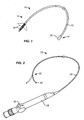
- a deployable sweeping structure 18 is disposed at the distal end of the sheath 12 and is shiftable between a low profile tubular configuration (shown in full line) and an open or deployed concave configuration (shown in broken line).
- a hub 20 is typically provided at the proximal end 14 of the sheath 12.
- the stone capture device 10 of the present invention is intended to be mounted over the steerable shaft 24 of a conventional viewing scope (26, Fig. 2 ), typically a ureteroscope, such as those commercially available from Olympus/ACMI.
- the viewing scope 26 further comprises a control handle 28 attached to a proximal end of the shaft 24.
- the control handle 28 includes a steering lever 30 which can be advanced and retracted to selectively deflect or "steer" a distal region 32 of the shaft 24, as shown in broken line.
- the control handle 28 will further include a connector for compiling a light source and an optical element of the viewing scope to a suitable screen and power source (not shown).
- a distal tip 40 of the steerable shaft 24 of the viewing scope 26 is introduced through the entire length of the sheath 12 of the stone capture device 10 so that said distal end is received in and attached to a distal tip 42 of the deployable sweeping structure.
- the deployable sweeping structure 18 is typically a woven or braided mesh, typically formed from polymeric or wire filaments or fibers, so that axial compression of the sweeping structure 18 from its tubular configuration (illustrated in Fig. 3 ) to a foreshortened configuration (as shown in Figs. 4A and 5A , will cause the sweeping structure to assume a concave configuration, more particularly a conical configuration.
- the sweeping structure will be fabricated so that it preferentially bends and everts about a weakened region 44, as shown in Figs. 4A and 5A .
- a distal most portion 46 of the sweeping structure 18 will preferentially evert into a proximal most portion 48.
- the steering structure progressively shortens with the forward diameter or width becoming larger.
- the sweeping structure in its tubular configuration has only a single wall and is thus relatively flexible, typically having a bending stiffness in the ranges set forth above.
- the wall becomes doubled, increasing the bending stiffness within the ranges set forth above.
- the relatively flexible tubular configuration is desirable since it will be over the steerable distal region 32 of the viewing scope. Thus, the viewing scope may be steered even while the sweeping structure 18 is over it.
- the sweeping structure When the sweeping structure is deployed, however, it will have more stiffness and rigidity to facilitate engaging and manipulating the urinary stones within the kidney or bladder. As the deployed sweeping structure is distal to the distal end of the steerable shaft 24, however, the structure will not interfere with steering and advancement.
- the sweeping structure mesh is preferably constructed from a wire braid. Usually eight to 36 wires are used to construct braid.
- the wire will usually be formed from a flexible metal or polymer material such as a superelastic nickle-titanium alloy (nitinol), a nylon, or a polyethylene terephthalate (PET).
- the sweeping structure 18 will further include a mechanism for drawing the open end closed after it has been partially or fully deployed.
- the structure to close the end is a simple filament or suture 60 which passes through the mid-section of the sweeping structure which becomes the forward edge of the sweeping structure after deployment.
- the filament acts as a purse string to draw the sweeping structure closed, as illustrated in Fig. 7D discussed below.
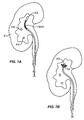
- the viewing scope 26 will be introduced into the urinary tract UT with a stone capture device 10 disposed thereover, as illustrated in Fig. 6 .
- the assembly of the viewing scope 26 and the stone capture device 10 is introduced in the same manner as a conventional ureteroscope without the stone capture device. That is, a distal end of the assembly of the present invention will be introduced through the urethra URTH into the bladder B, and optionally further through the ureter URE and into the kidney K.
- the non-deployed sweeping structure 18 and the distal region 32 of the viewing scope may be steered together using the lever 30 of the viewing scope which selectively deflects a distal portion of the shaft 24 of the viewing scope 26.
- the kidney K may have a number of kidney stones KS therein.
- the sweeping structure 18 and distal region 32 may be steered while the physician views through the optical element 70 of the viewing scope (illustrated in Figs. 4B and 5B ). While viewing, illumination will be provided by a light source 72 on the viewing scope.
- the sweeping structure 18 may be deployed, as shown in Fig. 7B .
- the combination stone capture device 10 and viewing scope 26 ( Fig. 2 ) may then be advanced, while continuing to optically view the region, until the deployed sweeping structure 18 engages a wall of the kidney, as shown in Fig.
- An optical (laser) fiber 80 or other stone fragmentation device may then be introduced through the working channel 74 ( Figs. 4B and 5B ) of the viewing scope and advanced into the region where the stone is captured.
- the stone will be fragmented.
- irrigation medium will be introduced simultaneously through the working channel to sweep the resulting stone fragments into the double-walled mesh of the deployed sweeping structure, thus simultaneously clearing the scope's field of view and entrapping the stone fragments therein.
- stones in the kidney are trapped within one of the cul-de-sac-like calices of the kidney.
- the sweeping structure may be advantageously deployed over the mouth of such a calyx to contain the stone and fragments produced by the lithotripsy process, in exactly the same manner as above.
- the filaments 60 may be retracted in order to close the sweeping structure 18 over the stone fragments, as shown in Fig. 7D .
- the combined assembly of the stone capture device 10 and the viewing scope 26 may be withdrawn from the urinary tract.
- the stone capture device 10 may be removed from the viewing scope 26, and the stone capture device will usually be disposed of in a conventional manner.
- the viewing scope can be sterilized and reused in subsequent procedures.
- an alternative perforate sweeping structure 100 comprises a carrier sleeve 102 attached at the distal end of a hypotube or other elongate tubular member 104.
- a pusher rod 106 extends coaxially through an inner passage or lumen of the hypotube 104 and is attached to a perforate sweeping structure 108 which is in a proximally retracted, radially collapsed configuration as shown in Fig. 8A .
- the self-expanding perforate sweeping structure 108 can be distally advanced so that it is released from the sleeve 102 and expands into an open conical configuration, as shown in Fig. 8B .
- a proximal end 112 of the perforate sweeping structure 108 will also expand to open and align with a passage or lumen 114 ( Fig. 8A ) which runs through the carrier sleeve 102.
- the sweeping structure assembly 100 may then advance over a viewing scope 120 ( Fig. 8B ) by advancing a proximal end of the scope into the passage 114 of the sleeve 102.
- the hypotube 104 may be used to distally advance the sleeve 102 over the viewing structure 120 until the sleeve 102 approaches a distal end 122 of the viewing scope 120, as best seen in Fig. 8B .
- the viewing scope 120 and/or the assembly of sleeve 102 and hypotube 104 may be manipulated to cause the deployed perforate sweeping structure 108 to capture kidney stones KS therein.
- kidney stones KS may be captured and energy applied through an optical fiber advanced through a working channel of the viewing scope 120 in order to disrupt the stones.
- the hypotube 104 may be retracted proximally in order to draw and collapse the sweeping structure 108 back into the passage 114 of sleeve 102 (as shown in Fig. 8C ), optionally after the viewing scope 120 has been at least partially retracted therein.
- the viewing scope and sweeping structure assembly 100 may then be withdrawn from the body cavity to remove the stones.
Landscapes
- Health & Medical Sciences (AREA)
- Life Sciences & Earth Sciences (AREA)
- Surgery (AREA)
- Engineering & Computer Science (AREA)
- Physics & Mathematics (AREA)
- General Health & Medical Sciences (AREA)
- Veterinary Medicine (AREA)
- Biomedical Technology (AREA)
- Heart & Thoracic Surgery (AREA)
- Medical Informatics (AREA)
- Molecular Biology (AREA)
- Animal Behavior & Ethology (AREA)
- Nuclear Medicine, Radiotherapy & Molecular Imaging (AREA)
- Public Health (AREA)
- Optics & Photonics (AREA)
- Orthopedic Medicine & Surgery (AREA)
- Vascular Medicine (AREA)
- Biophysics (AREA)
- Pathology (AREA)
- Radiology & Medical Imaging (AREA)
- Electromagnetism (AREA)
- Otolaryngology (AREA)
- Mechanical Engineering (AREA)
- Urology & Nephrology (AREA)
- Surgical Instruments (AREA)
- Endoscopes (AREA)
Claims (14)
- Dispositif de capture de calculs (10) adapté à des fins d'utilisation avec un instrument d'examen visuel orientable (26), ledit dispositif comportant :une gaine (12) ayant une extrémité distale (16), une extrémité proximale (14), et une lumière positionnable sur une tige (24) de l'instrument d'examen visuel (26) ; etune structure de balayage perforée (18) s'étendant dans le sens distal depuis l'extrémité distale de la gaine (12), dans lequel la structure de balayage perforée (18) est en mesure de changer entre une configuration tubulaire avec une largeur approximativement identique à celle de la gaine (12) et une configuration concave qui augmente en largeur dans le sens distal, dans lequel la structure de balayage (18) a une extrémité distale (42) agencée à des fins de réception et de fixation sur une extrémité distale de l'instrument d'examen visuel orientable (26) quand l'instrument d'examen visuel orientable (26) est disposé à l'intérieur de la structure de balayage perforée (18) et dans lequel la structure de balayage (18) est suffisamment flexible et pliable pour permettre l'orientation de l'instrument d'examen visuel orientable (26) à l'intérieur de la structure de balayage avant le déploiement jusqu'à la configuration concave.
- Dispositif selon la revendication 1, comportant par ailleurs :un moyen (60) permettant de fermer une extrémité distale de la structure de balayage concave déployée (18) à des fins de capture de fragments de calculs dans celle-ci.
- Dispositif selon la revendication 2, dans lequel le moyen permettant de fermer une extrémité distale de la structure concave déployée comporte un dispositif d'attache (60) s'étendant autour de l'extrémité distale de la structure de balayage concave déployée, dans lequel le dispositif d'attache (60) peut être resserré pour fermer l'extrémité distale.
- Dispositif selon la revendication 3, dans lequel la structure de balayage (18) comporte des filaments tissés ou tressés agencés sous la forme d'un tube en mailles qui peut être raccourci pour se retourner en une structure concave à double paroi.
- Dispositif selon la revendication 4, dans lequel la structure concave à double paroi a une géométrie généralement conique ou hémisphérique.
- Dispositif selon l'une quelconque des revendications précédentes, dans lequel la gaine (12) est configurée pour positionner la structure de balayage perforée (18) de manière distale sur une région distale de l'instrument d'examen visuel (26) quand la structure de balayage (18) est dans la configuration tubulaire et pour positionner la structure de balayage (18) de manière distale par rapport à l'instrument d'examen visuel (26) quand la structure de balayage (18) est dans sa configuration concave.
- Dispositif selon la revendication 6, dans lequel la structure de balayage (18) dans sa configuration concave est suffisamment rigide pour entrer en prise avec des calculs à l'intérieur d'une cavité corporelle et solliciter lesdits calculs contre une paroi de la cavité.
- Dispositif selon l'une quelconque des revendications précédentes, dans lequel la structure de balayage (18) dans sa configuration concave a une largeur qui fait au moins deux fois celle de la gaine (12), étant de préférence de deux fois à huit fois plus large par rapport à la largeur de la gaine.
- Dispositif selon l'une quelconque des revendications précédentes, dans lequel la gaine (12) a une longueur inférieure à celle de la tige (24) de l'instrument d'examen visuel associé (26).
- Dispositif selon l'une quelconque des revendications précédentes, dans lequel une extrémité distale (42) de la structure de balayage perforée (18) est en mesure d'être raccordée de manière amovible au niveau d'une extrémité distale de l'instrument d'examen visuel orientable (26), dans lequel une extrémité proximale de la structure peut être avancée de manière distale par la gaine (12) pour faire passer la structure de balayage (18) de sa configuration tubulaire à sa configuration conique.
- Dispositif selon l'une quelconque des revendications précédentes, comportant par ailleurs un emballage dans lequel le dispositif est maintenu dans l'emballage stérile.
- Système permettant de fragmenter et de capturer un calcul dans une cavité corporelle, ledit système comportant :un instrument d'examen visuel orientable (26) adapté à des fins d'introduction transurétrale au niveau du rein, ledit instrument d'examen ayant une tige (24) munie d'un élément visuel optique au niveau de son extrémité distale et un canal opérateur (74) ; etun dispositif (10) selon l'une quelconque des revendications précédentes, dans lequel le dispositif (10) est en mesure d'être reçu sur la tige (24) de l'instrument d'examen visuel orientable (26).
- Système selon la revendication 12, comportant par ailleurs un guide d'ondes optiques (80) en mesure d'avancer au travers du canal opérateur (74) et capable d'acheminer de l'énergie laser à des fins d'ablation d'un calcul capturé par la structure de balayage (18) du dispositif de capture de calculs (10).
- Système selon la revendication 13, comportant par ailleurs un outil mécanique en mesure d'avancer au travers du canal opérateur (74) et capable de détruire mécaniquement un calcul capturé par la structure de balayage (18) du dispositif de capture de calculs (10).
Applications Claiming Priority (3)
| Application Number | Priority Date | Filing Date | Title |
|---|---|---|---|
| US11880208P | 2008-12-01 | 2008-12-01 | |
| US17005509P | 2009-04-16 | 2009-04-16 | |
| PCT/US2009/066281 WO2010065556A1 (fr) | 2008-12-01 | 2009-12-01 | Procédés et systèmes pour capturer et éliminer des calculs urinaires de cavités corporelles |
Publications (3)
| Publication Number | Publication Date |
|---|---|
| EP2355717A1 EP2355717A1 (fr) | 2011-08-17 |
| EP2355717A4 EP2355717A4 (fr) | 2012-05-02 |
| EP2355717B1 true EP2355717B1 (fr) | 2014-02-19 |
Family
ID=42223485
Family Applications (1)
| Application Number | Title | Priority Date | Filing Date |
|---|---|---|---|
| EP09830998.2A Active EP2355717B1 (fr) | 2008-12-01 | 2009-12-01 | Systèmes pour capturer et éliminer des calculs urinaires de cavités corporelles |
Country Status (3)
| Country | Link |
|---|---|
| US (2) | US8986291B2 (fr) |
| EP (1) | EP2355717B1 (fr) |
| WO (1) | WO2010065556A1 (fr) |
Cited By (1)
| Publication number | Priority date | Publication date | Assignee | Title |
|---|---|---|---|---|
| US9931129B2 (en) | 2015-03-19 | 2018-04-03 | Gyrus Acmi, Inc. | Small fragment retrieval device |
Families Citing this family (58)
| Publication number | Priority date | Publication date | Assignee | Title |
|---|---|---|---|---|
| US7686825B2 (en) | 2004-03-25 | 2010-03-30 | Hauser David L | Vascular filter device |
| US9381028B2 (en) | 2010-10-15 | 2016-07-05 | Endogrowth (Proprietary) Limited | Inversible tubular member and a gripping device including such a member |
| EP2658483B1 (fr) * | 2010-12-30 | 2018-07-11 | Boston Scientific Scimed, Inc. | Panier de chargement pour système de mise en place d'une endoprothèse |
| JPWO2012132483A1 (ja) * | 2011-03-28 | 2014-07-24 | テルモ株式会社 | 生体組織保持用デバイス |
| GB2498349B (en) | 2012-01-10 | 2013-12-11 | Cook Medical Technologies Llc | Object capture device |
| CN102551886B (zh) * | 2012-03-28 | 2014-08-13 | 叶向东 | 激光光纤内聚排列式碎石清石吸引探杆装置 |
| US8784434B2 (en) | 2012-11-20 | 2014-07-22 | Inceptus Medical, Inc. | Methods and apparatus for treating embolism |
| WO2014159848A1 (fr) | 2013-03-14 | 2014-10-02 | The General Hospital Corporation | Système et procédé pour l'utilisation d'une endoprothèse urétérale anti-reflux souple |
| EP3459472B1 (fr) * | 2013-03-14 | 2020-05-13 | The General Hospital Corporation | Système pour l'élimination guidée à partir d'un sujet in vivo |
| US10406276B2 (en) | 2013-03-14 | 2019-09-10 | The General Hospital Corporation | System and method for guided removal from an in vivo subject |
| US9775675B2 (en) | 2013-03-14 | 2017-10-03 | The Charlotte-Mecklenburg Hospital Authority | Ureteroscope and associated method for the minimally invasive treatment of urinary stones |
| JP2016523631A (ja) * | 2013-06-14 | 2016-08-12 | アバンテック バスキュラー コーポレイション | 下大静脈フィルターおよび回収システム |
| WO2015061365A1 (fr) | 2013-10-21 | 2015-04-30 | Inceptus Medical, Llc | Procédés et appareil de traitement d'embolie |
| US20150305757A1 (en) * | 2014-04-28 | 2015-10-29 | NatEmack Holding, LLC | Method and apparatus for enclosure and removal of calculi and foreign bodies |
| US10265086B2 (en) | 2014-06-30 | 2019-04-23 | Neuravi Limited | System for removing a clot from a blood vessel |
| WO2016010995A1 (fr) * | 2014-07-15 | 2016-01-21 | Boston Scientific Scimed, Inc. | Dispositifs médicaux de prélèvement |
| CN104095665B (zh) * | 2014-07-15 | 2016-06-08 | 中国人民解放军第二军医大学 | 膜式输尿管结石阻挡取出器 |
| WO2016073530A1 (fr) | 2014-11-04 | 2016-05-12 | Avantec Vascular Corporation | Dispositif de cathéter doté de composants internes s'étendant longitudinalement et destiné à comprimer un os spongieux |
| CN107427353B (zh) | 2014-12-12 | 2020-11-03 | 阿万泰血管公司 | 具有插置支撑构件的下腔静脉过滤器收回系统 |
| US10278804B2 (en) | 2014-12-12 | 2019-05-07 | Avantec Vascular Corporation | IVC filter retrieval systems with releasable capture feature |
| WO2016112032A1 (fr) * | 2015-01-05 | 2016-07-14 | Boston Scientific Scimed, Inc. | Élément souple pour la résistance à un flux rétrograde |
| US10213091B2 (en) * | 2015-02-13 | 2019-02-26 | University Of Dammam | System, method, and apparatus for visualizing and identifying pathological tissue |
| EP4079237A1 (fr) | 2015-09-28 | 2022-10-26 | Stryker Corporation | Appareils de thrombectomie mécanique |
| EP4233744A3 (fr) | 2015-10-23 | 2023-11-01 | Inari Medical, Inc. | Dispositif pour le traitement intravasculaire d'occlusion vasculaire |
| US9955986B2 (en) | 2015-10-30 | 2018-05-01 | Auris Surgical Robotics, Inc. | Basket apparatus |
| US10231793B2 (en) | 2015-10-30 | 2019-03-19 | Auris Health, Inc. | Object removal through a percutaneous suction tube |
| US9949749B2 (en) | 2015-10-30 | 2018-04-24 | Auris Surgical Robotics, Inc. | Object capture with a basket |
| JP2019518484A (ja) * | 2016-04-14 | 2019-07-04 | ボストン サイエンティフィック サイムド,インコーポレイテッドBoston Scientific Scimed,Inc. | 医療システム、デバイス、及び関連方法 |
| CN113576607A (zh) | 2016-04-25 | 2021-11-02 | 斯瑞克公司 | 预加载的翻转牵引器血栓切除装置及方法 |
| US11497512B2 (en) | 2016-04-25 | 2022-11-15 | Stryker Corporation | Inverting thrombectomy apparatuses and methods |
| ES2859656T3 (es) | 2016-04-25 | 2021-10-04 | Stryker Corp | Aparatos de trombectomía antiatascamiento y macerante |
| JP6934935B2 (ja) | 2016-04-25 | 2021-09-15 | ストライカー コーポレイションStryker Corporation | 反転式機械的血栓除去装置、および血管内の使用方法 |
| US11896247B2 (en) | 2016-04-25 | 2024-02-13 | Stryker Corporation | Inverting mechanical thrombectomy apparatuses |
| JP6672479B2 (ja) | 2016-05-18 | 2020-03-25 | ジャイラス・エーシーエムアイ・インコーポレーテッド | レーザ砕石術のための装置及び方法 |
| EP4094699A1 (fr) | 2016-06-03 | 2022-11-30 | Stryker Corporation | Appareils de thrombectomie à inversion |
| WO2018049317A1 (fr) | 2016-09-12 | 2018-03-15 | Stryker Corporation | Appareils de thrombectomie autonomes et méthodes |
| FI3528717T3 (fi) | 2016-10-24 | 2024-08-09 | Inari Medical Inc | Laitteita verisuonitukoksen hoitamiseen |
| EP3558161A4 (fr) | 2016-12-22 | 2020-08-12 | Avantec Vascular Corporation | Systèmes, dispositifs et procédés pour des systèmes de récupération ayant un fil d'attache |
| CA3074564A1 (fr) | 2017-09-06 | 2019-03-14 | Inari Medical, Inc. | Soupapes hemostatiques et methodes d'utilisation |
| WO2019094456A1 (fr) | 2017-11-09 | 2019-05-16 | Stryker Corporation | Appareils de thrombectomie à inversion ayant un suivi amélioré |
| US11154314B2 (en) | 2018-01-26 | 2021-10-26 | Inari Medical, Inc. | Single insertion delivery system for treating embolism and associated systems and methods |
| EP3746144A4 (fr) | 2018-02-02 | 2021-11-24 | Calyxo, Inc. | Dispositifs et procédés d'élimination mini-invasive de calculs rénaux par aspiration et irrigation combinées |
| US20190282247A1 (en) | 2018-03-15 | 2019-09-19 | Gyrus Acmi, Inc. D/B/A Olympus Surgical Technologies America | Small fragment retrieval device |
| EP3793457A1 (fr) | 2018-05-14 | 2021-03-24 | Stryker Corporation | Appareils inverseurs de thrombectomie et procédés d'utilisation |
| EP3813739A4 (fr) | 2018-06-29 | 2022-04-13 | Avantec Vascular Corporation | Systèmes et procédés pour implants et dispositifs de déploiement |
| AU2019321256B2 (en) | 2018-08-13 | 2023-06-22 | Inari Medical, Inc. | System for treating embolism and associated devices and methods |
| EP3849440A1 (fr) | 2018-09-10 | 2021-07-21 | Stryker Corporation | Dispositif de préhension rainuré par laser |
| CN112969420A (zh) | 2018-09-10 | 2021-06-15 | 史赛克公司 | 翻转血栓切除术装置和血栓切除术装置的使用方法 |
| EP4295789A3 (fr) * | 2019-03-04 | 2024-02-21 | Neuravi Limited | Systèmes d'actionnement d'entonnoir |
| ES2910600T3 (es) | 2019-03-04 | 2022-05-12 | Neuravi Ltd | Catéter de recuperación de coágulos accionado |
| US11896330B2 (en) | 2019-08-15 | 2024-02-13 | Auris Health, Inc. | Robotic medical system having multiple medical instruments |
| EP4427686A2 (fr) | 2019-09-11 | 2024-09-11 | Neuravi Limited | Cathéter buccal extensible |
| AU2020368528A1 (en) | 2019-10-16 | 2022-04-21 | Inari Medical, Inc. | Systems, devices, and methods for treating vascular occlusions |
| CN114901200A (zh) | 2019-12-31 | 2022-08-12 | 奥瑞斯健康公司 | 高级篮式驱动模式 |
| US11944327B2 (en) | 2020-03-05 | 2024-04-02 | Neuravi Limited | Expandable mouth aspirating clot retrieval catheter |
| US11896249B2 (en) | 2020-07-02 | 2024-02-13 | Gyrus Acmi, Inc. | Lithotripsy system having a drill and lateral emitter |
| US11937839B2 (en) | 2021-09-28 | 2024-03-26 | Neuravi Limited | Catheter with electrically actuated expandable mouth |
| US12011186B2 (en) | 2021-10-28 | 2024-06-18 | Neuravi Limited | Bevel tip expandable mouth catheter with reinforcing ring |
Citations (4)
| Publication number | Priority date | Publication date | Assignee | Title |
|---|---|---|---|---|
| US4739760A (en) * | 1986-06-06 | 1988-04-26 | Thomas J. Fogarty | Vein valve cutter apparatus |
| DE19722429A1 (de) * | 1997-05-28 | 1998-12-03 | Optimed Medizinische Instr Gmb | Vorrichtung zum Einfangen und/oder Zerkleinern von Gegenständen in Hohlorganen |
| US20080058836A1 (en) * | 2006-08-03 | 2008-03-06 | Hansen Medical, Inc. | Systems and methods for performing minimally invasive procedures |
| WO2008028149A2 (fr) * | 2006-09-01 | 2008-03-06 | Voyage Medical, Inc. | Système de cartographie et de visualisation d'électrophysiologie |
Family Cites Families (114)
| Publication number | Priority date | Publication date | Assignee | Title |
|---|---|---|---|---|
| US2756752A (en) | 1953-12-23 | 1956-07-31 | Scherlis Irving | Surgical instrument |
| DE2157911C2 (de) | 1970-12-11 | 1982-02-04 | Marc Edmond Jean van Bruxelles Hoorn | Chirurgisches Gerät zum Abbinden von inneren Strukturen |
| US3830240A (en) | 1972-07-02 | 1974-08-20 | Blackstone Corp | Method and apparatus for disintegration of urinary calculi |
| US3870048A (en) | 1973-07-30 | 1975-03-11 | In Bae Yoon | Device for sterilizing the human female or male by ligation |
| US4124108A (en) | 1974-10-25 | 1978-11-07 | Phillips Paul E | Grain dispensing arrangement |
| US4046149A (en) | 1975-01-31 | 1977-09-06 | Olympus Optical Co., Ltd. | Instrument for removing a foreign substance from the body cavity of human being |
| US4030503A (en) | 1975-11-05 | 1977-06-21 | Clark Iii William T | Embolectomy catheter |
| US4030505A (en) | 1975-11-28 | 1977-06-21 | Calculus Instruments Ltd. | Method and device for disintegrating stones in human ducts |
| JPS5641684Y2 (fr) | 1977-11-24 | 1981-09-30 | ||
| US4222308A (en) | 1979-03-26 | 1980-09-16 | Arnett Perry J | Accuracy device for semi-automatic pistols |
| US4262677A (en) | 1979-03-26 | 1981-04-21 | Bader Robert F | Culture sampling device and method |
| US4257420A (en) | 1979-05-22 | 1981-03-24 | Olympus Optical Co., Ltd. | Ring applicator with an endoscope |
| US4295464A (en) | 1980-03-21 | 1981-10-20 | Shihata Alfred A | Ureteric stone extractor with two ballooned catheters |
| GB2116046B (en) | 1982-03-04 | 1985-05-22 | Wolf Gmbh Richard | Apparatus for disintegrating and removing calculi |
| US4606330A (en) | 1983-08-09 | 1986-08-19 | Richard Wolf Gmbh | Device for disintegrating stones in bodily cavities or ducts |
| US4706671A (en) | 1985-05-02 | 1987-11-17 | Weinrib Harry P | Catheter with coiled tip |
| JPS6237508U (fr) * | 1985-08-27 | 1987-03-05 | ||
| US4823793A (en) | 1985-10-30 | 1989-04-25 | The United States Of America As Represented By The Administrator Of The National Aeronuautics & Space Administration | Cutting head for ultrasonic lithotripsy |
| US4735194C1 (en) | 1987-01-13 | 2001-05-08 | Dept Of Veterans Affairs The U | Flexile endoscopic ligating instrument |
| US4748971A (en) | 1987-01-30 | 1988-06-07 | German Borodulin | Vibrational apparatus for accelerating passage of stones from ureter |
| US5154722A (en) | 1988-05-05 | 1992-10-13 | Circon Corporation | Electrohydraulic probe having a controlled discharge path |
| US4920954A (en) * | 1988-08-05 | 1990-05-01 | Sonic Needle Corporation | Ultrasonic device for applying cavitation forces |
| US5011488A (en) | 1988-12-07 | 1991-04-30 | Robert Ginsburg | Thrombus extraction system |
| US5041093A (en) * | 1990-01-31 | 1991-08-20 | Boston Scientific Corp. | Catheter with foraminous anchor |
| US5135534A (en) | 1990-04-06 | 1992-08-04 | John Tulip | Laser lithotripsy |
| EP0566694A1 (fr) | 1991-01-09 | 1993-10-27 | EndoMedix Corporation | Procede et dispositif de fluidification intracorporelle des tissus et/ou de fragmentation intracorporelle des calculs lors des operations chirurgicales endoscopiques |
| IT225683Y1 (it) | 1991-06-07 | 1997-01-13 | Roberto Feliziani | Catetere o sonda non inquinante. |
| US5531717A (en) | 1993-12-12 | 1996-07-02 | Rtc, Inc. | Non-contaminating probe and methods of making and using same |
| US5176688A (en) | 1991-07-17 | 1993-01-05 | Perinchery Narayan | Stone extractor and method |
| US5192286A (en) | 1991-07-26 | 1993-03-09 | Regents Of The University Of California | Method and device for retrieving materials from body lumens |
| US5599291A (en) | 1993-01-04 | 1997-02-04 | Menlo Care, Inc. | Softening expanding ureteral stent |
| US5320630A (en) | 1993-02-23 | 1994-06-14 | Munir Ahmed | Endoscopic ligating instrument for applying elastic bands |
| US5814058A (en) | 1993-03-05 | 1998-09-29 | Innerdyne, Inc. | Method and apparatus employing conformable sleeve for providing percutaneous access |
| US5431676A (en) | 1993-03-05 | 1995-07-11 | Innerdyne Medical, Inc. | Trocar system having expandable port |
| JP2958219B2 (ja) | 1993-08-20 | 1999-10-06 | 住友ベークライト株式会社 | 内視鏡的結紮用キット |
| US5476450A (en) | 1993-11-04 | 1995-12-19 | Ruggio; Joseph M. | Apparatus and method for aspirating intravascular, pulmonary and cardiac obstructions |
| US5403324A (en) | 1994-01-14 | 1995-04-04 | Microsonic Engineering Devices Company, Inc. | Flexible catheter with stone basket and ultrasonic conductor |
| US5454790A (en) | 1994-05-09 | 1995-10-03 | Innerdyne, Inc. | Method and apparatus for catheterization access |
| US6171329B1 (en) | 1994-12-19 | 2001-01-09 | Gore Enterprise Holdings, Inc. | Self-expanding defect closure device and method of making and using |
| US5879366A (en) | 1996-12-20 | 1999-03-09 | W.L. Gore & Associates, Inc. | Self-expanding defect closure device and method of making and using |
| US6350266B1 (en) * | 1995-02-02 | 2002-02-26 | Scimed Life Systems, Inc. | Hybrid stone retrieval device |
| US5676688A (en) | 1995-02-06 | 1997-10-14 | Rtc, Inc. | Variably inflatable medical device |
| US5979452A (en) | 1995-06-07 | 1999-11-09 | General Surgical Innovations, Inc. | Endoscopic linton procedure using balloon dissectors and retractors |
| US5716321A (en) * | 1995-10-10 | 1998-02-10 | Conceptus, Inc. | Method for maintaining separation between a falloposcope and a tubal wall |
| US5860972A (en) | 1995-10-26 | 1999-01-19 | Xintec Corporation | Method of detection and destruction of urinary calculi and similar structures |
| US6849069B1 (en) | 1995-11-07 | 2005-02-01 | Boston Scientitfic Corporation | Medical device with tail(s) for assisting flow of urine |
| US6800080B1 (en) * | 1996-05-03 | 2004-10-05 | Scimed Life Systems, Inc. | Medical retrieval device |
| US6099535A (en) | 1996-06-06 | 2000-08-08 | C.R. Bard, Inc. | Hydraulically actuated multiband ligator |
| US5972019A (en) | 1996-07-25 | 1999-10-26 | Target Therapeutics, Inc. | Mechanical clot treatment device |
| AU4068797A (en) | 1996-08-14 | 1998-03-06 | Anna Maria Bigonzi-Jaker | Membranes suitable for medical use |
| US6210370B1 (en) | 1997-01-10 | 2001-04-03 | Applied Medical Resources Corporation | Access device with expandable containment member |
| US5906622A (en) | 1997-04-29 | 1999-05-25 | Lippitt; Robert G. | Positively expanded and retracted medical extractor |
| US5836913A (en) | 1997-05-02 | 1998-11-17 | Innerdyne, Inc. | Device and method for accessing a body cavity |
| WO1998051370A1 (fr) | 1997-05-12 | 1998-11-19 | Rtc, Inc. | Membrane electriquement conductrice a usage medical |
| US6039748A (en) | 1997-08-05 | 2000-03-21 | Femrx, Inc. | Disposable laparoscopic morcellator |
| JP4121615B2 (ja) * | 1997-10-31 | 2008-07-23 | オリンパス株式会社 | 内視鏡 |
| US6602265B2 (en) | 1998-02-10 | 2003-08-05 | Artemis Medical, Inc. | Tissue separation medical device and method |
| EP1059887A1 (fr) | 1998-03-06 | 2000-12-20 | Curon Medical, Inc. | Appareil pour le traitement electrochirurgical du sphincter oesophagien |
| CA2323623C (fr) | 1998-03-27 | 2009-09-29 | Cook Urological Inc. | Dispositif medical de prelevement peu vulnerant |
| JP2002503140A (ja) | 1998-04-23 | 2002-01-29 | サイムド ライフ システムズ,インコーポレイテッド | 非外傷性医用回収装置 |
| US5989264A (en) | 1998-06-11 | 1999-11-23 | Ethicon Endo-Surgery, Inc. | Ultrasonic polyp snare |
| US6491685B2 (en) | 1999-03-04 | 2002-12-10 | The Regents Of The University Of California | Laser and acoustic lens for lithotripsy |
| US7214229B2 (en) | 1999-03-18 | 2007-05-08 | Fossa Medical, Inc. | Radially expanding stents |
| US6709465B2 (en) | 1999-03-18 | 2004-03-23 | Fossa Medical, Inc. | Radially expanding ureteral device |
| US6214037B1 (en) | 1999-03-18 | 2001-04-10 | Fossa Industries, Llc | Radially expanding stent |
| US6368328B1 (en) | 1999-09-16 | 2002-04-09 | Scimed Life Systems, Inc. | Laser-resistant medical retrieval device |
| US6663622B1 (en) | 2000-02-11 | 2003-12-16 | Iotek, Inc. | Surgical devices and methods for use in tissue ablation procedures |
| US6264664B1 (en) * | 2000-03-10 | 2001-07-24 | General Science And Technology Corp. | Surgical basket devices |
| US6440061B1 (en) * | 2000-03-24 | 2002-08-27 | Donald E. Wenner | Laparoscopic instrument system for real-time biliary exploration and stone removal |
| KR20020093109A (ko) | 2000-05-02 | 2002-12-12 | 윌슨-쿡 메디컬 인크. | 뒤집힐 수 있는 슬리브가 구비된 카테터 o.t.l.용삽입기 장치 |
| US6869395B2 (en) | 2000-05-15 | 2005-03-22 | C. R. Bard, Inc. | Endoscopic accessory attachment mechanism |
| US6764519B2 (en) | 2000-05-26 | 2004-07-20 | Scimed Life Systems, Inc. | Ureteral stent |
| DE10031661C2 (de) | 2000-06-29 | 2003-04-24 | Johannes Woitzik | Schutzhülle für Biopsiekanüle |
| US6824545B2 (en) * | 2000-06-29 | 2004-11-30 | Concentric Medical, Inc. | Systems, methods and devices for removing obstructions from a blood vessel |
| US6500185B1 (en) | 2000-09-29 | 2002-12-31 | Primus Medical, Inc. | Snare device |
| JP3758962B2 (ja) | 2000-10-11 | 2006-03-22 | ペンタックス株式会社 | 内視鏡用バスケット型回収具 |
| US20040092956A1 (en) | 2000-11-03 | 2004-05-13 | John Liddicoat | Catheter for removal of solids from surgical drains |
| US6645195B1 (en) | 2001-01-05 | 2003-11-11 | Advanced Cardiovascular Systems, Inc. | Intraventricularly guided agent delivery system and method of use |
| EP1294286B1 (fr) | 2001-01-08 | 2005-12-07 | Boston Scientific Limited | Panier de retrait avec embout liberable |
| US6814739B2 (en) | 2001-05-18 | 2004-11-09 | U.S. Endoscopy Group, Inc. | Retrieval device |
| US20030023247A1 (en) | 2001-07-03 | 2003-01-30 | Lind Stuart J. | Medical retrieval device with cable protection means |
| US6740096B2 (en) | 2002-01-16 | 2004-05-25 | Scimed Life Systems, Inc. | Treatment and removal of objects in anatomical lumens |
| US6695834B2 (en) | 2002-01-25 | 2004-02-24 | Scimed Life Systems, Inc. | Apparatus and method for stone removal from a body |
| ATE500777T1 (de) | 2002-01-30 | 2011-03-15 | Tyco Healthcare | Chirurgische bildgebende vorrichtung |
| US6780161B2 (en) | 2002-03-22 | 2004-08-24 | Fmd, Llc | Apparatus for extracorporeal shock wave lithotripter using at least two shock wave pulses |
| WO2004021868A2 (fr) | 2002-09-06 | 2004-03-18 | C.R. Bard, Inc. | Systeme de commande a accessoire endoscopique externe |
| EP1542577B1 (fr) | 2002-09-06 | 2016-05-25 | C.R. Bard, Inc. | Adaptateur de fixation d'accessoire endoscopique |
| FR2844446B1 (fr) | 2002-09-17 | 2004-11-26 | Porges Sa | Extracteur chirurgical pour l'extraction de corps etrangers a travers des voies naturelles ou chirurgicales |
| US7998163B2 (en) | 2002-10-03 | 2011-08-16 | Boston Scientific Scimed, Inc. | Expandable retrieval device |
| US20050228481A1 (en) | 2002-10-09 | 2005-10-13 | Fossa Medical, Inc | Eccentric lumen stents |
| US7682366B2 (en) * | 2002-10-16 | 2010-03-23 | Olympus Corporation | Calculus manipulation apparatus |
| US7655021B2 (en) | 2003-03-10 | 2010-02-02 | Boston Scientific Scimed, Inc. | Dilator with expandable member |
| US7597704B2 (en) | 2003-04-28 | 2009-10-06 | Atritech, Inc. | Left atrial appendage occlusion device with active expansion |
| US7731722B2 (en) * | 2003-07-31 | 2010-06-08 | Vance Products Incorporated | Ureteral backstop filter and retrieval device |
| US7377925B2 (en) * | 2003-09-16 | 2008-05-27 | Minimally Invasive Devices, Llc | Fragmentation and extraction basket |
| US20050080448A1 (en) * | 2003-09-18 | 2005-04-14 | Kear Jason W. | Medical retrieval devices and related methods of use |
| US6929664B2 (en) | 2003-12-05 | 2005-08-16 | Fossa Medical, Inc. | Open lumen stents |
| CA2556935A1 (fr) * | 2004-02-19 | 2005-09-01 | Applied Medical Resources Corporation | Gaine de capture pour embolectomie |
| US20050197627A1 (en) | 2004-03-05 | 2005-09-08 | Percutaneous Systems, Inc. | Method and system for deploying protective sleeve in intraluminal catherization and dilation |
| US7572274B2 (en) | 2004-05-27 | 2009-08-11 | Cardiva Medical, Inc. | Self-tensioning vascular occlusion device and method for its use |
| US8142445B2 (en) * | 2004-05-06 | 2012-03-27 | Boston Scientific Scimed, Inc. | Stone retrieval device and related methods of manufacture |
| US20050267488A1 (en) | 2004-05-13 | 2005-12-01 | Omnisonics Medical Technologies, Inc. | Apparatus and method for using an ultrasonic medical device to treat urolithiasis |
| US7883516B2 (en) | 2004-07-07 | 2011-02-08 | Percutaneous Systems, Inc. | Methods for removing kidney stones from the ureter |
| US7462183B2 (en) | 2004-07-07 | 2008-12-09 | Percutaneous Systems, Inc. | Methods for deploying conformed structures in body lumens |
| US7972292B2 (en) | 2005-07-06 | 2011-07-05 | Percutaneous Systems, Inc. | Methods and apparatus for deploying ureteral stents |
| US20060116693A1 (en) | 2004-12-01 | 2006-06-01 | Weisenburgh William B Ii | Apparatus and method for stone capture and removal |
| WO2006060492A2 (fr) | 2004-12-01 | 2006-06-08 | Ethicon Endo-Surgery, Inc. | Dispositif a ultrasons et procede de traitement de calculs a l'interieur du corps |
| US8252017B2 (en) * | 2005-10-18 | 2012-08-28 | Cook Medical Technologies Llc | Invertible filter for embolic protection |
| US20070106233A1 (en) | 2005-10-20 | 2007-05-10 | Percutaneous Systems, Inc. | Systems and methods for dilating and accessing body lumens |
| WO2007092506A2 (fr) * | 2006-02-08 | 2007-08-16 | Vance Products Incorporated D/B/A Cook Urological Incorporated | Dispositif de prise et de retrait d'irrigation |
| US8062282B2 (en) | 2006-02-13 | 2011-11-22 | Fossa Medical, Inc. | Methods and apparatus for temporarily occluding body openings |
| US8475489B2 (en) | 2007-07-13 | 2013-07-02 | Percutaneous Systems, Inc. | Apparatus for occluding body lumens |
| US8088140B2 (en) * | 2008-05-19 | 2012-01-03 | Mindframe, Inc. | Blood flow restorative and embolus removal methods |
| WO2009086482A1 (fr) * | 2007-12-26 | 2009-07-09 | Lazarus Effect, Inc. | Systèmes de retrait et procédés pour les utiliser |
-
2009
- 2009-12-01 US US12/628,382 patent/US8986291B2/en not_active Expired - Fee Related
- 2009-12-01 EP EP09830998.2A patent/EP2355717B1/fr active Active
- 2009-12-01 WO PCT/US2009/066281 patent/WO2010065556A1/fr active Application Filing
-
2015
- 2015-02-13 US US14/622,114 patent/US20150223828A1/en not_active Abandoned
Patent Citations (4)
| Publication number | Priority date | Publication date | Assignee | Title |
|---|---|---|---|---|
| US4739760A (en) * | 1986-06-06 | 1988-04-26 | Thomas J. Fogarty | Vein valve cutter apparatus |
| DE19722429A1 (de) * | 1997-05-28 | 1998-12-03 | Optimed Medizinische Instr Gmb | Vorrichtung zum Einfangen und/oder Zerkleinern von Gegenständen in Hohlorganen |
| US20080058836A1 (en) * | 2006-08-03 | 2008-03-06 | Hansen Medical, Inc. | Systems and methods for performing minimally invasive procedures |
| WO2008028149A2 (fr) * | 2006-09-01 | 2008-03-06 | Voyage Medical, Inc. | Système de cartographie et de visualisation d'électrophysiologie |
Cited By (1)
| Publication number | Priority date | Publication date | Assignee | Title |
|---|---|---|---|---|
| US9931129B2 (en) | 2015-03-19 | 2018-04-03 | Gyrus Acmi, Inc. | Small fragment retrieval device |
Also Published As
| Publication number | Publication date |
|---|---|
| EP2355717A4 (fr) | 2012-05-02 |
| US20150223828A1 (en) | 2015-08-13 |
| US8986291B2 (en) | 2015-03-24 |
| EP2355717A1 (fr) | 2011-08-17 |
| WO2010065556A1 (fr) | 2010-06-10 |
| US20100137846A1 (en) | 2010-06-03 |
Similar Documents
| Publication | Publication Date | Title |
|---|---|---|
| EP2355717B1 (fr) | Systèmes pour capturer et éliminer des calculs urinaires de cavités corporelles | |
| US8636651B2 (en) | Medical immobilization device and related methods of use | |
| US10092278B2 (en) | Endoscopes having multiple lumens for tissue acquisition and removal and related methods of use | |
| US8979870B2 (en) | Distal release retrieval assembly and related methods of use | |
| US20130211415A1 (en) | Steerable tissue manipulation medical devices and related methods of use | |
| JP2018134534A (ja) | 血管内異物除去用カテーテル | |
| US7377925B2 (en) | Fragmentation and extraction basket | |
| US20080188866A1 (en) | Apparatus and methods for removing relatively large and small stones from a body passage | |
| US9629649B2 (en) | Tissue resection bander and related methods of use | |
| JP2017526463A (ja) | 回収装置 | |
| JP7189023B2 (ja) | 尿道内処置用微侵襲性器具 | |
| WO2006060658A2 (fr) | Dispositif et procede destines a la capture et a l'elimination de calculs | |
| US20060224178A1 (en) | Expandable medical retrieval device and related methods of use | |
| US11134967B2 (en) | Thrombectomy catheter and methods of use | |
| US11229451B2 (en) | Thrombectomy catheter and methods of use | |
| US20170348015A1 (en) | Methods and systems for removing tissue from body cavities | |
| US20070185520A1 (en) | Detachable medical immobilization device and related methods of use | |
| US20150157344A1 (en) | Medical retrieval devices and related methods of use | |
| CA2996667A1 (fr) | Dispositif de manipulation de corps etrangers dans des organes creux (variantes) | |
| JP2023554648A (ja) | 胆道鏡システムの案内シースおよび係留ワイヤ | |
| CN116600695A (zh) | 胆道镜系统导引护套和锚固线 |
Legal Events
| Date | Code | Title | Description |
|---|---|---|---|
| PUAI | Public reference made under article 153(3) epc to a published international application that has entered the european phase |
Free format text: ORIGINAL CODE: 0009012 |
|
| 17P | Request for examination filed |
Effective date: 20110613 |
|
| AK | Designated contracting states |
Kind code of ref document: A1 Designated state(s): AT BE BG CH CY CZ DE DK EE ES FI FR GB GR HR HU IE IS IT LI LT LU LV MC MK MT NL NO PL PT RO SE SI SK SM TR |
|
| AX | Request for extension of the european patent |
Extension state: AL BA RS |
|
| A4 | Supplementary search report drawn up and despatched |
Effective date: 20120330 |
|
| RIC1 | Information provided on ipc code assigned before grant |
Ipc: A61B 17/221 20060101ALI20120326BHEP Ipc: A61B 17/22 20060101AFI20120326BHEP |
|
| 17Q | First examination report despatched |
Effective date: 20121123 |
|
| GRAP | Despatch of communication of intention to grant a patent |
Free format text: ORIGINAL CODE: EPIDOSNIGR1 |
|
| INTG | Intention to grant announced |
Effective date: 20130709 |
|
| GRAS | Grant fee paid |
Free format text: ORIGINAL CODE: EPIDOSNIGR3 |
|
| GRAA | (expected) grant |
Free format text: ORIGINAL CODE: 0009210 |
|
| AK | Designated contracting states |
Kind code of ref document: B1 Designated state(s): AT BE BG CH CY CZ DE DK EE ES FI FR GB GR HR HU IE IS IT LI LT LU LV MC MK MT NL NO PL PT RO SE SI SK SM TR |
|
| AX | Request for extension of the european patent |
Extension state: AL BA RS |
|
| REG | Reference to a national code |
Ref country code: GB Ref legal event code: FG4D |
|
| REG | Reference to a national code |
Ref country code: CH Ref legal event code: EP |
|
| REG | Reference to a national code |
Ref country code: AT Ref legal event code: REF Ref document number: 652650 Country of ref document: AT Kind code of ref document: T Effective date: 20140315 |
|
| REG | Reference to a national code |
Ref country code: DE Ref legal event code: R096 Ref document number: 602009021936 Country of ref document: DE Effective date: 20140403 |
|
| REG | Reference to a national code |
Ref country code: IE Ref legal event code: FG4D |
|
| REG | Reference to a national code |
Ref country code: NL Ref legal event code: VDEP Effective date: 20140219 |
|
| REG | Reference to a national code |
Ref country code: AT Ref legal event code: MK05 Ref document number: 652650 Country of ref document: AT Kind code of ref document: T Effective date: 20140219 |
|
| REG | Reference to a national code |
Ref country code: LT Ref legal event code: MG4D |
|
| PG25 | Lapsed in a contracting state [announced via postgrant information from national office to epo] |
Ref country code: LT Free format text: LAPSE BECAUSE OF FAILURE TO SUBMIT A TRANSLATION OF THE DESCRIPTION OR TO PAY THE FEE WITHIN THE PRESCRIBED TIME-LIMIT Effective date: 20140219 Ref country code: NO Free format text: LAPSE BECAUSE OF FAILURE TO SUBMIT A TRANSLATION OF THE DESCRIPTION OR TO PAY THE FEE WITHIN THE PRESCRIBED TIME-LIMIT Effective date: 20140519 Ref country code: IS Free format text: LAPSE BECAUSE OF FAILURE TO SUBMIT A TRANSLATION OF THE DESCRIPTION OR TO PAY THE FEE WITHIN THE PRESCRIBED TIME-LIMIT Effective date: 20140619 |
|
| PG25 | Lapsed in a contracting state [announced via postgrant information from national office to epo] |
Ref country code: ES Free format text: LAPSE BECAUSE OF FAILURE TO SUBMIT A TRANSLATION OF THE DESCRIPTION OR TO PAY THE FEE WITHIN THE PRESCRIBED TIME-LIMIT Effective date: 20140219 Ref country code: PT Free format text: LAPSE BECAUSE OF FAILURE TO SUBMIT A TRANSLATION OF THE DESCRIPTION OR TO PAY THE FEE WITHIN THE PRESCRIBED TIME-LIMIT Effective date: 20140619 Ref country code: NL Free format text: LAPSE BECAUSE OF FAILURE TO SUBMIT A TRANSLATION OF THE DESCRIPTION OR TO PAY THE FEE WITHIN THE PRESCRIBED TIME-LIMIT Effective date: 20140219 Ref country code: SE Free format text: LAPSE BECAUSE OF FAILURE TO SUBMIT A TRANSLATION OF THE DESCRIPTION OR TO PAY THE FEE WITHIN THE PRESCRIBED TIME-LIMIT Effective date: 20140219 Ref country code: AT Free format text: LAPSE BECAUSE OF FAILURE TO SUBMIT A TRANSLATION OF THE DESCRIPTION OR TO PAY THE FEE WITHIN THE PRESCRIBED TIME-LIMIT Effective date: 20140219 Ref country code: FI Free format text: LAPSE BECAUSE OF FAILURE TO SUBMIT A TRANSLATION OF THE DESCRIPTION OR TO PAY THE FEE WITHIN THE PRESCRIBED TIME-LIMIT Effective date: 20140219 Ref country code: CY Free format text: LAPSE BECAUSE OF FAILURE TO SUBMIT A TRANSLATION OF THE DESCRIPTION OR TO PAY THE FEE WITHIN THE PRESCRIBED TIME-LIMIT Effective date: 20140219 |
|
| PG25 | Lapsed in a contracting state [announced via postgrant information from national office to epo] |
Ref country code: BE Free format text: LAPSE BECAUSE OF FAILURE TO SUBMIT A TRANSLATION OF THE DESCRIPTION OR TO PAY THE FEE WITHIN THE PRESCRIBED TIME-LIMIT Effective date: 20140219 Ref country code: HR Free format text: LAPSE BECAUSE OF FAILURE TO SUBMIT A TRANSLATION OF THE DESCRIPTION OR TO PAY THE FEE WITHIN THE PRESCRIBED TIME-LIMIT Effective date: 20140219 Ref country code: LV Free format text: LAPSE BECAUSE OF FAILURE TO SUBMIT A TRANSLATION OF THE DESCRIPTION OR TO PAY THE FEE WITHIN THE PRESCRIBED TIME-LIMIT Effective date: 20140219 |
|
| PG25 | Lapsed in a contracting state [announced via postgrant information from national office to epo] |
Ref country code: CZ Free format text: LAPSE BECAUSE OF FAILURE TO SUBMIT A TRANSLATION OF THE DESCRIPTION OR TO PAY THE FEE WITHIN THE PRESCRIBED TIME-LIMIT Effective date: 20140219 Ref country code: DK Free format text: LAPSE BECAUSE OF FAILURE TO SUBMIT A TRANSLATION OF THE DESCRIPTION OR TO PAY THE FEE WITHIN THE PRESCRIBED TIME-LIMIT Effective date: 20140219 Ref country code: EE Free format text: LAPSE BECAUSE OF FAILURE TO SUBMIT A TRANSLATION OF THE DESCRIPTION OR TO PAY THE FEE WITHIN THE PRESCRIBED TIME-LIMIT Effective date: 20140219 Ref country code: RO Free format text: LAPSE BECAUSE OF FAILURE TO SUBMIT A TRANSLATION OF THE DESCRIPTION OR TO PAY THE FEE WITHIN THE PRESCRIBED TIME-LIMIT Effective date: 20140219 |
|
| REG | Reference to a national code |
Ref country code: DE Ref legal event code: R097 Ref document number: 602009021936 Country of ref document: DE |
|
| PG25 | Lapsed in a contracting state [announced via postgrant information from national office to epo] |
Ref country code: PL Free format text: LAPSE BECAUSE OF FAILURE TO SUBMIT A TRANSLATION OF THE DESCRIPTION OR TO PAY THE FEE WITHIN THE PRESCRIBED TIME-LIMIT Effective date: 20140219 Ref country code: SK Free format text: LAPSE BECAUSE OF FAILURE TO SUBMIT A TRANSLATION OF THE DESCRIPTION OR TO PAY THE FEE WITHIN THE PRESCRIBED TIME-LIMIT Effective date: 20140219 |
|
| PLBE | No opposition filed within time limit |
Free format text: ORIGINAL CODE: 0009261 |
|
| STAA | Information on the status of an ep patent application or granted ep patent |
Free format text: STATUS: NO OPPOSITION FILED WITHIN TIME LIMIT |
|
| 26N | No opposition filed |
Effective date: 20141120 |
|
| REG | Reference to a national code |
Ref country code: DE Ref legal event code: R097 Ref document number: 602009021936 Country of ref document: DE Effective date: 20141120 |
|
| PG25 | Lapsed in a contracting state [announced via postgrant information from national office to epo] |
Ref country code: IT Free format text: LAPSE BECAUSE OF FAILURE TO SUBMIT A TRANSLATION OF THE DESCRIPTION OR TO PAY THE FEE WITHIN THE PRESCRIBED TIME-LIMIT Effective date: 20140219 |
|
| PG25 | Lapsed in a contracting state [announced via postgrant information from national office to epo] |
Ref country code: SI Free format text: LAPSE BECAUSE OF FAILURE TO SUBMIT A TRANSLATION OF THE DESCRIPTION OR TO PAY THE FEE WITHIN THE PRESCRIBED TIME-LIMIT Effective date: 20140219 |
|
| PG25 | Lapsed in a contracting state [announced via postgrant information from national office to epo] |
Ref country code: LU Free format text: LAPSE BECAUSE OF FAILURE TO SUBMIT A TRANSLATION OF THE DESCRIPTION OR TO PAY THE FEE WITHIN THE PRESCRIBED TIME-LIMIT Effective date: 20141201 |
|
| REG | Reference to a national code |
Ref country code: CH Ref legal event code: PL |
|
| REG | Reference to a national code |
Ref country code: IE Ref legal event code: MM4A |
|
| PG25 | Lapsed in a contracting state [announced via postgrant information from national office to epo] |
Ref country code: LI Free format text: LAPSE BECAUSE OF NON-PAYMENT OF DUE FEES Effective date: 20141231 Ref country code: IE Free format text: LAPSE BECAUSE OF NON-PAYMENT OF DUE FEES Effective date: 20141201 Ref country code: CH Free format text: LAPSE BECAUSE OF NON-PAYMENT OF DUE FEES Effective date: 20141231 |
|
| REG | Reference to a national code |
Ref country code: FR Ref legal event code: PLFP Year of fee payment: 7 |
|
| PG25 | Lapsed in a contracting state [announced via postgrant information from national office to epo] |
Ref country code: SM Free format text: LAPSE BECAUSE OF FAILURE TO SUBMIT A TRANSLATION OF THE DESCRIPTION OR TO PAY THE FEE WITHIN THE PRESCRIBED TIME-LIMIT Effective date: 20140219 |
|
| PG25 | Lapsed in a contracting state [announced via postgrant information from national office to epo] |
Ref country code: MC Free format text: LAPSE BECAUSE OF FAILURE TO SUBMIT A TRANSLATION OF THE DESCRIPTION OR TO PAY THE FEE WITHIN THE PRESCRIBED TIME-LIMIT Effective date: 20140219 |
|
| PG25 | Lapsed in a contracting state [announced via postgrant information from national office to epo] |
Ref country code: BG Free format text: LAPSE BECAUSE OF FAILURE TO SUBMIT A TRANSLATION OF THE DESCRIPTION OR TO PAY THE FEE WITHIN THE PRESCRIBED TIME-LIMIT Effective date: 20140219 Ref country code: GR Free format text: LAPSE BECAUSE OF FAILURE TO SUBMIT A TRANSLATION OF THE DESCRIPTION OR TO PAY THE FEE WITHIN THE PRESCRIBED TIME-LIMIT Effective date: 20140520 |
|
| PG25 | Lapsed in a contracting state [announced via postgrant information from national office to epo] |
Ref country code: HU Free format text: LAPSE BECAUSE OF FAILURE TO SUBMIT A TRANSLATION OF THE DESCRIPTION OR TO PAY THE FEE WITHIN THE PRESCRIBED TIME-LIMIT; INVALID AB INITIO Effective date: 20091201 Ref country code: MT Free format text: LAPSE BECAUSE OF FAILURE TO SUBMIT A TRANSLATION OF THE DESCRIPTION OR TO PAY THE FEE WITHIN THE PRESCRIBED TIME-LIMIT Effective date: 20140219 Ref country code: TR Free format text: LAPSE BECAUSE OF FAILURE TO SUBMIT A TRANSLATION OF THE DESCRIPTION OR TO PAY THE FEE WITHIN THE PRESCRIBED TIME-LIMIT Effective date: 20140219 |
|
| REG | Reference to a national code |
Ref country code: FR Ref legal event code: PLFP Year of fee payment: 8 |
|
| REG | Reference to a national code |
Ref country code: FR Ref legal event code: PLFP Year of fee payment: 9 |
|
| PG25 | Lapsed in a contracting state [announced via postgrant information from national office to epo] |
Ref country code: MK Free format text: LAPSE BECAUSE OF FAILURE TO SUBMIT A TRANSLATION OF THE DESCRIPTION OR TO PAY THE FEE WITHIN THE PRESCRIBED TIME-LIMIT Effective date: 20140219 |
|
| PGFP | Annual fee paid to national office [announced via postgrant information from national office to epo] |
Ref country code: GB Payment date: 20181227 Year of fee payment: 10 Ref country code: FR Payment date: 20181226 Year of fee payment: 10 |
|
| PGFP | Annual fee paid to national office [announced via postgrant information from national office to epo] |
Ref country code: DE Payment date: 20181231 Year of fee payment: 10 |
|
| REG | Reference to a national code |
Ref country code: DE Ref legal event code: R119 Ref document number: 602009021936 Country of ref document: DE |
|
| GBPC | Gb: european patent ceased through non-payment of renewal fee |
Effective date: 20191201 |
|
| PG25 | Lapsed in a contracting state [announced via postgrant information from national office to epo] |
Ref country code: DE Free format text: LAPSE BECAUSE OF NON-PAYMENT OF DUE FEES Effective date: 20200701 Ref country code: GB Free format text: LAPSE BECAUSE OF NON-PAYMENT OF DUE FEES Effective date: 20191201 Ref country code: FR Free format text: LAPSE BECAUSE OF NON-PAYMENT OF DUE FEES Effective date: 20191231 |