EP2354257B1 - Düsenstock - Google Patents
Düsenstock Download PDFInfo
- Publication number
- EP2354257B1 EP2354257B1 EP11000894.3A EP11000894A EP2354257B1 EP 2354257 B1 EP2354257 B1 EP 2354257B1 EP 11000894 A EP11000894 A EP 11000894A EP 2354257 B1 EP2354257 B1 EP 2354257B1
- Authority
- EP
- European Patent Office
- Prior art keywords
- nozzle
- thermal insulation
- nozzle fitting
- insulation material
- compensator
- Prior art date
- Legal status (The legal status is an assumption and is not a legal conclusion. Google has not performed a legal analysis and makes no representation as to the accuracy of the status listed.)
- Active
Links
- 238000009413 insulation Methods 0.000 claims description 27
- 239000012774 insulation material Substances 0.000 claims description 23
- 239000004033 plastic Substances 0.000 claims description 7
- 229920003023 plastic Polymers 0.000 claims description 7
- 239000000126 substance Substances 0.000 claims description 6
- 238000004519 manufacturing process Methods 0.000 claims description 5
- 238000000034 method Methods 0.000 claims description 5
- 239000011819 refractory material Substances 0.000 claims description 5
- 239000011888 foil Substances 0.000 claims description 4
- 230000005855 radiation Effects 0.000 claims description 4
- 239000000463 material Substances 0.000 claims 2
- 238000005538 encapsulation Methods 0.000 claims 1
- RMAQACBXLXPBSY-UHFFFAOYSA-N silicic acid Chemical compound O[Si](O)(O)O RMAQACBXLXPBSY-UHFFFAOYSA-N 0.000 claims 1
- 235000012239 silicon dioxide Nutrition 0.000 claims 1
- 239000003570 air Substances 0.000 description 8
- 238000000465 moulding Methods 0.000 description 7
- XEEYBQQBJWHFJM-UHFFFAOYSA-N Iron Chemical compound [Fe] XEEYBQQBJWHFJM-UHFFFAOYSA-N 0.000 description 4
- VYPSYNLAJGMNEJ-UHFFFAOYSA-N Silicium dioxide Chemical compound O=[Si]=O VYPSYNLAJGMNEJ-UHFFFAOYSA-N 0.000 description 4
- 230000009467 reduction Effects 0.000 description 4
- 239000003795 chemical substances by application Substances 0.000 description 3
- BPQQTUXANYXVAA-UHFFFAOYSA-N Orthosilicate Chemical compound [O-][Si]([O-])([O-])[O-] BPQQTUXANYXVAA-UHFFFAOYSA-N 0.000 description 2
- 238000005253 cladding Methods 0.000 description 2
- 238000005265 energy consumption Methods 0.000 description 2
- 229910052742 iron Inorganic materials 0.000 description 2
- 239000002184 metal Substances 0.000 description 2
- 229910052751 metal Inorganic materials 0.000 description 2
- 239000000203 mixture Substances 0.000 description 2
- 239000003605 opacifier Substances 0.000 description 2
- 239000002985 plastic film Substances 0.000 description 2
- 229920006255 plastic film Polymers 0.000 description 2
- 239000000377 silicon dioxide Substances 0.000 description 2
- 238000003466 welding Methods 0.000 description 2
- 229910000805 Pig iron Inorganic materials 0.000 description 1
- 239000004952 Polyamide Substances 0.000 description 1
- 239000004698 Polyethylene Substances 0.000 description 1
- 229910000831 Steel Inorganic materials 0.000 description 1
- 239000000853 adhesive Substances 0.000 description 1
- 230000001070 adhesive effect Effects 0.000 description 1
- 239000012080 ambient air Substances 0.000 description 1
- 239000003245 coal Substances 0.000 description 1
- 239000000571 coke Substances 0.000 description 1
- 238000002485 combustion reaction Methods 0.000 description 1
- 239000000470 constituent Substances 0.000 description 1
- 238000010276 construction Methods 0.000 description 1
- 230000035699 permeability Effects 0.000 description 1
- 230000000704 physical effect Effects 0.000 description 1
- 229920002647 polyamide Polymers 0.000 description 1
- -1 polyethylene Polymers 0.000 description 1
- 229920000573 polyethylene Polymers 0.000 description 1
- 239000000843 powder Substances 0.000 description 1
- 230000001698 pyrogenic effect Effects 0.000 description 1
- 238000009419 refurbishment Methods 0.000 description 1
- 238000007493 shaping process Methods 0.000 description 1
- 239000010959 steel Substances 0.000 description 1
- 230000007704 transition Effects 0.000 description 1
Images


Classifications
-
- C—CHEMISTRY; METALLURGY
- C21—METALLURGY OF IRON
- C21B—MANUFACTURE OF IRON OR STEEL
- C21B7/00—Blast furnaces
- C21B7/16—Tuyéres
-
- C—CHEMISTRY; METALLURGY
- C21—METALLURGY OF IRON
- C21B—MANUFACTURE OF IRON OR STEEL
- C21B7/00—Blast furnaces
- C21B7/04—Blast furnaces with special refractories
- C21B7/06—Linings for furnaces
-
- C—CHEMISTRY; METALLURGY
- C21—METALLURGY OF IRON
- C21B—MANUFACTURE OF IRON OR STEEL
- C21B7/00—Blast furnaces
- C21B7/16—Tuyéres
- C21B7/163—Blowpipe assembly
-
- F—MECHANICAL ENGINEERING; LIGHTING; HEATING; WEAPONS; BLASTING
- F27—FURNACES; KILNS; OVENS; RETORTS
- F27B—FURNACES, KILNS, OVENS, OR RETORTS IN GENERAL; OPEN SINTERING OR LIKE APPARATUS
- F27B1/00—Shaft or like vertical or substantially vertical furnaces
- F27B1/10—Details, accessories, or equipment peculiar to furnaces of these types
- F27B1/12—Shells or casings; Supports therefor
- F27B1/14—Arrangements of linings
-
- F—MECHANICAL ENGINEERING; LIGHTING; HEATING; WEAPONS; BLASTING
- F27—FURNACES; KILNS; OVENS; RETORTS
- F27B—FURNACES, KILNS, OVENS, OR RETORTS IN GENERAL; OPEN SINTERING OR LIKE APPARATUS
- F27B1/00—Shaft or like vertical or substantially vertical furnaces
- F27B1/10—Details, accessories, or equipment peculiar to furnaces of these types
- F27B1/16—Arrangements of tuyeres
-
- F—MECHANICAL ENGINEERING; LIGHTING; HEATING; WEAPONS; BLASTING
- F27—FURNACES; KILNS; OVENS; RETORTS
- F27D—DETAILS OR ACCESSORIES OF FURNACES, KILNS, OVENS, OR RETORTS, IN SO FAR AS THEY ARE OF KINDS OCCURRING IN MORE THAN ONE KIND OF FURNACE
- F27D1/00—Casings; Linings; Walls; Roofs
- F27D1/0003—Linings or walls
- F27D1/0023—Linings or walls comprising expansion joints or means to restrain expansion due to thermic flows
-
- F—MECHANICAL ENGINEERING; LIGHTING; HEATING; WEAPONS; BLASTING
- F27—FURNACES; KILNS; OVENS; RETORTS
- F27D—DETAILS OR ACCESSORIES OF FURNACES, KILNS, OVENS, OR RETORTS, IN SO FAR AS THEY ARE OF KINDS OCCURRING IN MORE THAN ONE KIND OF FURNACE
- F27D1/00—Casings; Linings; Walls; Roofs
- F27D1/0003—Linings or walls
- F27D1/0033—Linings or walls comprising heat shields, e.g. heat shieldsd
-
- F—MECHANICAL ENGINEERING; LIGHTING; HEATING; WEAPONS; BLASTING
- F27—FURNACES; KILNS; OVENS; RETORTS
- F27D—DETAILS OR ACCESSORIES OF FURNACES, KILNS, OVENS, OR RETORTS, IN SO FAR AS THEY ARE OF KINDS OCCURRING IN MORE THAN ONE KIND OF FURNACE
- F27D3/00—Charging; Discharging; Manipulation of charge
- F27D3/16—Introducing a fluid jet or current into the charge
-
- F—MECHANICAL ENGINEERING; LIGHTING; HEATING; WEAPONS; BLASTING
- F16—ENGINEERING ELEMENTS AND UNITS; GENERAL MEASURES FOR PRODUCING AND MAINTAINING EFFECTIVE FUNCTIONING OF MACHINES OR INSTALLATIONS; THERMAL INSULATION IN GENERAL
- F16L—PIPES; JOINTS OR FITTINGS FOR PIPES; SUPPORTS FOR PIPES, CABLES OR PROTECTIVE TUBING; MEANS FOR THERMAL INSULATION IN GENERAL
- F16L59/00—Thermal insulation in general
- F16L59/14—Arrangements for the insulation of pipes or pipe systems
- F16L59/147—Arrangements for the insulation of pipes or pipe systems the insulation being located inwardly of the outer surface of the pipe
Definitions
- the invention relates to a nozzle for introducing hot blast into a shaft furnace, in particular blast furnace, comprising at least one joint compensator, a nozzle manifold and a nozzle tip, each having a metallic outer structure, which is provided on its inner side facing the hot blast with a refractory inner lining, wherein the Joint compensator connected at one end to the nozzle manifold and connectable to the other end with a hot blast line.
- the invention further proposes a method for producing a nozzle block formed from at least one joint compensator, a nozzle manifold and a nozzle tip, with which hot blast can be introduced into a shaft furnace, in particular a blast furnace, after the first metallic outer structures for the joint compensator, the nozzle manifold and the nozzle tip are provided, which are then filled with a refractory material to produce a refractory inner lining.
- hot air In order to reduce the energy consumption during iron production by means of a shaft furnace, hot air, called hot blast in the metallurgical industry, is blown into a shaft furnace at a temperature in the range of about 1200 ° C. to 1350 ° C.
- hot blast in the metallurgical industry
- ambient air is heated to a desired and nearly constant temperature by means of a hot-air heater heated area.
- the hot blast generated in this way is fed to the shaft furnace via a hot blast line system.
- the hot blast first passes from the hot blast to a hot blast line of the hot blast line system which extends around it in a lower section of the shaft furnace. From this hot blast line, the hot blast is then guided to several circumferentially distributed around the shaft furnace arranged nozzle sticks, which are also referred to as hot blast nozzle sticks.
- the nozzle sticks have as terminations of the hot air duct system in each case a nozzle tip, which are usually connected in the region between the coal sack and the catch of the shaft furnace with this and partially pro
- the hot air duct system Due to the high temperatures of the hot blast, it is necessary to reduce energy losses and to increase the service life of the hot air duct system to provide said components of the system on their sides facing the hot blast with a heat-insulating, refractory inner lining. This is especially true for the nozzle sticks, which are each composed of a plurality of interconnected components. Before assembling these components to a nozzle assembly, it is necessary to provide the components individually with the refractory lining. According to the prior art, the refractory inner lining is usually arranged directly on the hot wind-facing inside of the metallic outer structure of such a component.
- the metallic outer structures are usually made of steel and are designed differently for the various components of a nozzle block.
- the metallic outer structure of the nozzle tip is formed substantially conical.
- the joint compensator for example, a tubular-shaped metallic outer structure.
- the nozzle assembly comprises a nozzle manifold, the metallic outer structure is constructed much more complex than the nozzle tip and the joint compensator.
- these different shaped, supporting metal parts of the nozzle block with the more general term "metallic external structure".
- the refractory lining of the hot blast pipe system and the nozzle block causes the temperature on the outer surface of the metal exterior structures to be reduced to about 300 ° C to 350 ° C. It can thus reduce energy losses. In addition, the safety in the work areas on the outside of the blast furnace is improved.
- the joint compensator is used to compensate for deformations of the hot air duct system that occur as a result of the thermal load.
- Articulating joints are usually equipped with cardan joints and bellows, which are arranged in transition areas to the other components of a nozzle block.
- cardan joints and bellows which are arranged in transition areas to the other components of a nozzle block.
- the refractory inner linings of the directly adjoining components bear as close as possible to each other.
- nozzle sticks Since nozzle sticks are exposed to the described high thermal loads, they must be worked up from time to time, that is provided with a new refractory lining.
- the removal of the spent refractory lining is usually done using rotary hammers and similar tools and is correspondingly expensive.
- damage to the sensitive elements of the Gelenkkompensatoren for example, on the bellows, and on the hot wind facing inside of the metallic outer structure occur.
- a nozzle assembly of the type mentioned above in that it has at least one thermal insulation element arranged at least in a partial area between the metallic outer structure and the refractory inner lining of the joint compensator, nozzle manifold and / or nozzle tip, which has a high-temperature-resistant thermal insulation material embedded in a covering wherein the envelope is formed as a foil, which consists essentially of plastic and the envelope largely dissolves during the intended use of the nozzle block.
- the arrangement according to the invention of the additional thermal insulation element between the metallic outer structure and the refractory inner lining of at least one component of the nozzle block causes the energy loss via the nozzle assembly to be further reduced.
- the temperature on the outside of the nozzle block or the surface of the metallic outer structure of its constituents according to the invention by about 100 ° C to 150 ° C over a conventional nozzle, i. without additional heat insulation element, can be reduced. This represents a significant energy saving, which can be represented in coke per ton of pig iron produced.
- the service life of the nozzle block is significantly increased by the lower thermal load of the metallic outer structures and the elements of the joint compensator. During the intended use of the nozzle assembly, the film burns and thus dissolves as far as possible.
- the plastic may be, for example, polyethylene or polyamide and a mixture thereof. Furthermore, a metallized plastic is also considered.
- the additional thermal insulation element weakens the bond between the metallic outer structure and the refractory lining, since the envelope largely dissolves during the intended use of the nozzle block, in particular burns. This makes it possible in comparison to nozzle sticks of the prior art with significantly less effort to remove the refractory inner lining during refurbishment of the nozzle block of the metallic outer structures. This results in a further cost reduction.
- thermal insulation elements are used for a nozzle, which are arranged at particularly sensitive points of the nozzle assembly, such as in the region of the Gelenkkompensators.
- the thermal insulation material has at least one inorganic, silicate substance.
- the inorganic, siliceous substance is a highly dispersive (pyrogenic) silica.
- Such inorganic, silicate substances have a very low thermal conductivity and thus serve to provide a thermal insulation element with excellent thermal insulation properties.
- a further advantageous embodiment of the invention provides that the thermal insulation material has at least one means for reducing the heat radiation transport within the thermal insulation material.
- Such agents are also referred to as opacifiers and serve to reduce the permeability of the thermal insulation material with respect to infrared radiation, wherein the opacifier can scatter and / or absorb infrared radiation.
- This embodiment is useful in the nozzle assembly according to the invention, since the thermal insulation properties of thermal insulation materials without the Addition of a clouding agent with increasing temperature deteriorate.
- the thermal insulation material is formed in powder form and pressed into a shaped body. Moldings with a wide variety of geometries can be produced in order to be able to adapt the insulation element ideally to its respective site of use.
- the shaped body is rod-shaped. It can also be provided to embed several moldings in a common enclosure. In particular, a plurality of rod-shaped moldings can be positioned parallel to each other at a small distance within the enclosure. If an envelope made of plastic is selected, then a flexible thermal insulation element can be formed, the shape of which can be easily adapted to its respective site of use while deforming.
- the thermal insulation material is evacuated and welded into the enclosure.
- evacuating the thermal insulation properties of the thermal insulation material and thus of the thermal insulation element are further improved by the proportion of heat transfer generated in the use of the thermal insulation element by convection within the thermal insulation material is reduced.
- Welding the compressed thermal insulation material into the enclosure further causes the thermal insulation element to reliably maintain its shape and physical properties during manufacture of the nozzle assembly.
- the thermal insulation element is glued to the metallic outer structure.
- a thermal insulation element can thus be connected in a simple manner with the respective metallic outer structure before attaching the refractory inner lining.
- a flexibly formed thermal insulation element can thus be easily and permanently positioned at its respective desired location.
- a method of the type mentioned above is further proposed according to the present invention at the respective hot air facing inside of the metallic outer structure of joint compensator, nozzle manifold and / or nozzle tip prior to pouring it with the refractory material at least one thermal element at least in a partial area is arranged on the inside, which is formed in advance by welding a powdered, compressed into a molding thermal insulation material in a sheath, which dissolves during the intended use of the nozzle block as much as possible.
- the method according to the invention is also associated with the advantages of energy saving and reduction of operating costs of a shaft furnace mentioned above with regard to the nozzle.
- a foil which is essentially formed from plastic is advantageously used as the envelope.
- the thermal insulation element is glued to the metallic outer structure.
- FIG. 1a shows in perspective an exemplary embodiment of the nozzle tip 1 of a nozzle block according to the invention, not shown.
- the nozzle tip 1 When the nozzle tip 1 is used as intended, hot blast flows through it and exits from the outlet opening 2. At the other end, the nozzle tip 1 is connectable to the nozzle manifold 3 of the nozzle block, of which an exemplary embodiment in the FIGS. 2a and 2b is shown.
- Envelope 1 feeders 4 are arranged on the outside of the nozzle tip over which the combustion process in the shaft furnace optimizing substances are supplied to the hot blast stream.
- FIG. 1b shows a longitudinal section through the in FIG. 1a It can be seen the supporting, metallic outer structure 5, which is provided on its side facing the hot air inside with a refractory inner lining 6.
- a thermal insulation element 7 is arranged between the metallic outer structure 5 and the refractory inner lining 6.
- This heat-insulating element 7 has an unspecified, embedded in a cladding, high temperature resistant thermal insulation material, wherein the enclosure largely dissolves during the intended use of the nozzle block, in particular burns.
- the feeders 4 each have a feed channel 8 which extends through the refractory inner lining 6 and in the passage 9 of the nozzle tip. 1 empties.
- Figure 1c shows the nozzle tip 1 of FIGS. 1a and 1b in a longitudinal section along the line BB in FIG. 1b , It can be seen in particular the mouth of the feed channel 8 in the passageway 9. Furthermore, the construction according to the invention of the nozzle tip 1 can be seen, according to which a thermal insulation element 7 is arranged between the metallic outer structure 5 and the refractory inner lining 6.
- FIG. 2a shows in perspective an embodiment of the nozzle 3 of a nozzle block according to the invention.
- the nozzle manifold 3 is above the flange 10 with the joint compensator 15, as exemplified in FIG. 3 shown, connectable. With the flange 11 at the other end of the nozzle manifold 3 is connected to the nozzle tip 1.
- the nozzle manifold 3 has a branch 12, which is closed by a flap 13, which is pivotable about a hinge 14.
- FIG. 2b shows a longitudinal section through the in FIG. 2a It can be seen that the nozzle manifold 3 has the structure according to the invention, according to which a thermal insulation element 7 is arranged between the metallic outer structure 5 and the refractory inner lining 6.
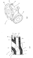
- FIG. 3 shows an exploded view of an embodiment of a joint compensator 15 of the nozzle block.
- This can be connected via the flange 16 with the nozzle manifold 3.
- the flange 17 of the joint compensator 15 is connected to a hot blast line, not shown, a hot air duct system.
- the joint compensator 15 has not shown bellows.
- the middle piece 19, which likewise has a metallic outer structure 5 lined with refractory material, can be connected to the connecting piece 21 via the element 20 to form a universal joint.
- the element 20 also has a metallic outer structure 5 and a so equipped Fireproof interior lining 6 on.
- the joint compensator 15 also has a plurality of differently designed thermal insulation elements 7. These are formed according to the invention by an embedded in a cladding, refractory thermal insulation material.
- the envelope is given by a plastic film which includes a plurality of rod-shaped moldings of the thermal insulation material.
- the rod-shaped moldings are aligned parallel to each other and to the longitudinal extent of the Gelenkkompensators 15. They consist of a compressed to the moldings, powdery mixture of highly dispersible silica and a clouding agent.
- the heat-insulating elements 7 are designed to be flexible and can be adapted to the respective shaping of the other components of the joint compensator 15 at their respective destination without great expenditure of force.
- the plastic film burns due to the high temperatures and thus dissolves as much as possible.
Landscapes
- Engineering & Computer Science (AREA)
- Chemical & Material Sciences (AREA)
- Mechanical Engineering (AREA)
- General Engineering & Computer Science (AREA)
- Manufacturing & Machinery (AREA)
- Materials Engineering (AREA)
- Metallurgy (AREA)
- Organic Chemistry (AREA)
- Furnace Housings, Linings, Walls, And Ceilings (AREA)
- Structures Of Non-Positive Displacement Pumps (AREA)
Description
- Die Erfindung betrifft einen Düsenstock zum Einleiten von Heißwind in einen Schachtofen, insbesondere Hochofen, aufweisend wenigstens einen Gelenkkompensator, einen Düsenkrümmer sowie eine Düsenspitze, welche jeweils eine metallische Außenstruktur aufweisen, die an ihrer dem Heißwind zugewandten Innenseite mit einer feuerfesten Innenauskleidung versehen ist, wobei der Gelenkkompensator mit einem Ende mit dem Düsenkrümmer verbunden und mit dem anderen Ende mit einer Heißwindringleitung verbindbar ist.
- Mit der Erfindung wird weiter ein Verfahren zum Herstellen eines aus zumindest einem Gelenkkompensator, einem Düsenkrümmer und einer Düsenspitze gebildeten Düsenstocks, mit dem Heißwind in einen Schachtofen, insbesondere Hochofen, einleitbar ist, vorgeschlagen, nach dem zunächst metallische Außenstrukturen für den Gelenkkompensator, den Düsenkrümmer und die Düsenspitze bereitgestellt werden, welche anschließend mit einem feuerfesten Material zur Erzeugung einer feuerfesten Innenauskleidung ausgegossen werden.
- Um den Energieverbrauch bei der Eisenherstellung mittels eines Schachtofens zu reduzieren, wird Heißluft, im Hüttenwesen Heißwind genannt, mit einer Temperatur im Bereich von etwa 1200°C bis 1350°C in einen Schachtofen eingeblasen. Hierzu wird für gewöhnlich Umgebungsluft mittels eines Winderhitzers auf eine gewünschte und nahezu konstante Temperatur in dem genannten Bereich erhitzt. Der so erzeugte Heißwind wird über ein Heißwindleitungssystem dem Schachtofen zugeführt. Dabei gelangt der Heißwind zunächst von dem Winderhitzer zu einer Heißwindringleitung des Heißwindleitungssystems, welche sich in einem unteren Abschnitt des Schachtofens um diesen herum erstreckt. Von dieser Heißwindringleitung wird der Heißwind anschließend zu mehreren umfänglich um den Schachtofen verteilt angeordneten Düsenstöcken geführt, welche auch als Heißwinddüsenstöcke bezeichnet werden. Die Düsenstöcke weisen als Abschlüsse des Heißwindleitungssystems jeweils eine Düsenspitze auf, die üblicherweise im Bereich zwischen Kohlensack und Rast des Schachtofens mit diesem verbunden sind und in diesen teilweise hineinragen.
- Aufgrund der hohen Temperaturen des Heißwindes ist es zur Reduzierung von Energieverlusten und zur Erhöhung von Standzeiten des Heißwindleitungssystems erforderlich, die genannten Komponenten des Systems auf ihren dem Heißwind zugewandten Innenseiten mit einer wärmedämmenden, feuerfesten Innenauskleidung zu versehen. Dieses gilt insbesondere auch für die Düsenstöcke, welche jeweils aus mehreren miteinander verbundenen Bestandteilen zusammengesetzt sind. Vor dem Zusammenbau dieser Bestandteile zu einem Düsenstock ist es erforderlich, die Bestandteile einzeln mit der feuerfesten Innenauskleidung zu versehen. Gemäß dem Stand der Technik wird die feuerfeste Innenauskleidung meist unmittelbar an der dem Heißwind zugewandten Innenseite der metallischen Außenstruktur eines solchen Bestandteils angeordnet.
- Die metallischen Außenstrukturen bestehen für gewöhnlich aus Stahl und sind für die verschiedenen Bestandteile eines Düsenstocks unterschiedlich ausgebildet. Beispielsweise ist die metallische Außenstruktur der Düsenspitze im Wesentlichen konusförmig ausgebildet. Hingegen weist der Gelenkkompensator beispielsweise eine rohrförmig ausgebildete metallische Außenstruktur auf. Des Weiteren umfasst der Düsenstock einen Düsenkrümmer, dessen metallische Außenstruktur deutlich komplexer aufgebaut ist als bei der Düsenspitze und dem Gelenkkompensator. Im Rahmen der Erfindung werden diese unterschiedliche geformten, tragenden Metallteile des Düsenstocks mit dem allgemeineren Ausdruck "metallische Außenstruktur" umschrieben.
- Die feuerfeste Innenauskleidung des Heißwindringleitungssystems und des Düsenstocks bewirkt, dass die Temperatur an der äußeren Oberfläche der metallischen Außenstrukturen auf etwa 300°C bis 350°C reduziert ist. Es lassen sich somit Energieverluste vermindern. Zudem wird die Sicherheit in den Arbeitsbereichen an der Außenseite des Hochofens verbessert.
- Der Gelenkkompensator dient der Kompensation von aufgrund der thermischen Belastung auftretenden Verformungen des Heißwindleitungssystems. Gelenkkompensatoren sind für gewöhnlich mit Kardangelenken und Wellenbälgen ausgestattet, die in Übergangsbereichen zu den weiteren Bestandteilen eines Düsenstocks angeordnet sind. Zum Schutz der empfindlichen Kompensatorenelemente vor den hohen thermischen Belastungen ist es erforderlich, dass die feuerfesten Innenauskleidungen der unmittelbar aneinander angrenzenden Bestandteile möglichst dicht aneinander anliegen.
- Weil Düsenstöcke den beschriebenen hohen thermischen Belastungen ausgesetzt sind, müssen sie von Zeit zu Zeit aufgearbeitet, das heißt mit einer neuen feuerfesten Innenauskleidung versehen werden. Das Entfernen der verbrauchten feuerfesten Innenauskleidung erfolgt meist unter Einsatz von Bohrhämmern und ähnlichem Werkzeug und ist entsprechend aufwendig. Zudem kommt es häufig vor, dass Schäden an den empfindlichen Elementen der Gelenkkompensatoren, beispielsweise an den Wellenbälgen, und an der dem Heißwind zugewandten Innenseite der metallischen Außenstruktur auftreten.
- Vor diesem Hintergrund ist es die Aufgabe der Erfindung, einen Düsenstock bereitzustellen, mit dem neben der weitestgehenden Senkung des bei der Herstellung von Eisen verbundenen Energieverbrauchs auch eine Reduzierung der allgemeinen Betriebskosten des Schachtofens möglich ist.
- Diese Aufgabe wird bei einem Düsenstock der eingangs genannten Art dadurch gelöst, dass dieser wenigstens ein zumindest in einem Teilbereich zwischen der metallischen Außenstruktur und der feuerfesten Innenauskleidung von Gelenkkompensator, Düsenkrümmer und/oder Düsenspitze angeordnetes Wärmedämmelement aufweist, das ein in eine Umhüllung eingebettetes, hochtemperaturfestes Wärmedämmmaterial aufweist, wobei die Umhüllung als Folie ausgebildet ist, die im Wesentlichen aus Kunststoff besteht und sich die Umhüllung während des bestimmungsgemäßen Einsatzes des Düsenstocks weitestgehend auflöst.
- Die erfindungsgemäße Anordnung des zusätzlichen Wärmedämmelementes zwischen metallischer Außenstruktur und feuerfester Innenauskleidung zumindest eines Bestandteils des Düsenstocks bewirkt, dass der Energieverlust über den Düsenstock weiter reduziert wird. Die Temperatur an der Außenseite des Düsenstocks beziehungsweise der Oberfläche der metallischen Außenstruktur seiner Bestandteile kann gemäß der Erfindung um etwa 100°C bis 150°C gegenüber einem herkömmlichen Düsenstock, d.h. ohne zusätzliches Wärmedämmelement, reduziert werden. Dies entspricht einer deutlichen Energieeinsparung, die sich in Koks pro Tonne hergestelltem Roheisen darstellen lässt. Zudem wird durch die geringere thermische Belastung der metallischen Außenstrukturen und der Elemente des Gelenkkompensators die Standzeit des Düsenstocks deutlich erhöht. Während des bestimmungsgemäßen Einsatzes des Düsenstocks verbrennt die Folie und löst sich somit weitestgehend auf. Bei dem Kunststoff kann es sich beispielsweise um Polyethylen oder Polyamid sowie eine Mischung daraus handeln. Des Weiteren kommt auch ein metallisierter Kunststoff in Betracht.
- Bei dem erfindungsgemäßen Düsenstock schwächt das zusätzliche Wärmedämmelement den Verbund zwischen der metallischen Außenstruktur und der feuerfesten Innenauskleidung, da sich die Umhüllung während des bestimmungsgemäßen Einsatzes des Düsenstocks weitestgehend auflöst, insbesondere verbrennt. Hierdurch ist es im Vergleich zu Düsenstöcken des Standes der Technik mit deutlich geringerem Aufwand möglich, die feuerfeste Innenauskleidung beim Aufarbeiten des Düsenstocks von den metallischen Außenstrukturen zu entfernen. Hierdurch ergibt sich eine weitere Kostenreduzierung.
- Insgesamt stellt die Verwendung des erfindungsgemäßen Düsenstocks bezüglich Betriebskosten und Energieeffizienz gegenüber der Verwendung herkömmlicher Düsenstöcke eine deutlich kostengünstigere Alternative dar.
- Im Rahmen der Erfindung kann vorgesehen sein, dass mehrere, insbesondere unterschiedlich ausgebildete, Wärmedämmelemente für einen Düsenstock verwendet werden, welche an besonders empfindlichen Stellen des Düsenstocks, wie beispielsweise im Bereich des Gelenkkompensators, angeordnet werden.
- Nach einer weiteren vorteilhaften Ausgestaltung der Erfindung weist das Wärmedämmmaterial wenigstens eine anorganische, silikatische Substanz auf. Vorzugsweise ist die anorganische, silikatische Substanz eine hochdispersive (pyrogene) Kieselsäure. Derartige anorganische, silikatische Substanzen weisen eine sehr geringe Wärmeleitfähigkeit auf und dienen somit der Schaffung eines Wärmedämmelementes mit hervorragenden Wärmedämmeigenschaften.
- Eine weitere vorteilhafte Ausgestaltung der Erfindung sieht vor, dass das Wärmedämmmaterial wenigstens ein Mittel zum Reduzieren des Wärmestrahlungstransports innerhalb des Wärmedämmmaterials aufweist. Solche Mittel werden auch als Trübungsmittel bezeichnet und dienen der Verringerung der Durchlässigkeit des Wärmedämmmaterials bezüglich Infrarotstrahlung, wobei das Trübungsmittel Infrarotstrahlung streuen und/oder absorbieren kann. Diese Ausgestaltung ist bei dem erfindungsgemäßen Düsenstock sinnvoll, da sich die Wärmedämmeigenschaften von Wärmedämmmaterialien ohne den Zusatz eines Trübungsmittels mit zunehmender Temperatur verschlechtern.
- Vorzugsweise ist das Wärmedämmmaterial pulverförmig ausgebildet und zu einem Formkörper verpresst. Es lassen sich so Formkörper mit unterschiedlichsten Geometrien herstellen, um das Dämmelement ideal an seinen jeweiligen Einsatzort anpassen zu können. Vorzugsweise ist der Formkörper stabförmig ausgebildet. Es kann auch vorgesehen sein, mehrere Formkörper in eine gemeinsame Umhüllung einzubetten. Insbesondere können mehrere stabförmig ausgebildete Formkörper parallel zueinander mit geringem Abstand innerhalb der Umhüllung positioniert sein. Wird eine Umhüllung aus Kunststoff gewählt, kann so ein flexibles Wärmedämmelement ausgebildet werden, dessen Formgebung unter Verformung sehr einfach an seinen jeweiligen Einsatzort anpassbar ist.
- Es wird weiter vorgeschlagen, dass das Wärmedämmmaterial evakuiert und in die Umhüllung eingeschweißt ist. Durch das Evakuieren werden die Wärmedämmeigenschaften des Wärmedämmmaterials und somit des Wärmedämmelementes weiter verbessert, indem der Anteil der beim Einsatz des Wärmedämmelementes durch Konvektion erzeugten Wärmeübertragung innerhalb des Wärmedämmmaterials reduziert wird. Das Einschweißen des verpressten Wärmedämmmaterials in die Umhüllung bewirkt weiter, dass das Wärmedämmelement während der Herstellung des Düsenstocks seine Form und physikalischen Eigenschaften zuverlässig beibehält.
- Ferner wird vorgeschlagen, dass das Wärmedämmelement mit der metallischen Außenstruktur verklebt ist. Ein solches Wärmedämmelement lässt sich somit vor dem Anbringen der feuerfesten Innenauskleidung auf einfache Art und Weise mit der jeweiligen metallischen Außenstruktur verbinden. Insbesondere ein flexibel ausgebildetes Wärmedämmelement kann somit einfach und dauerhaft an seinem jeweilig gewünschten Einsatzort positioniert werden. Nach Anbringen der feuerfesten Innenauskleidung, z.B. durch Ausgießen der metallischen Außenstruktur mit Feuerfestbeton bekannter Art, wird das Wärmedämmelement durch die feuerfeste Innenauskleidung fixiert. Der verwendete Kleber kann sich somit während des Betriebs des Düsenstocks durch Verbrennen auflösen.
- Zur Lösung der obigen Aufgabe wird weiter ein Verfahren der eingangs genannten Art vorgeschlagen, nach dem erfindungsgemäß an der jeweiligen dem Heißwind zugewandten Innenseite der metallischen Außenstruktur von Gelenkkompensator, Düsenkrümmer und/oder Düsenspitze vor deren Ausgießen mit dem feuerfesten Material wenigstens ein Wärmedämmelement zumindest in einem Teilbereich auf der Innenseite angeordnet wird, welches vorab durch Einschweißen eines pulverförmigen, zu einem Formkörper verpressten Wärmedämmmaterials in eine Umhüllung gebildet wird, die sich während des bestimmungsgemäßen Einsatzes des Düsenstocks weitestgehend auflöst.
- Auch das erfindungsgemäße Verfahren ist mit den oben bezogen auf den Düsenstock genannten Vorteilen der Energieersparnis und Verringerung von Betriebskosten eines Schachtofens verbunden. Dabei wird vorteilhafterweise als Umhüllung eine Folie verwendet, die im Wesentlichen aus Kunststoff gebildet ist. Vorzugsweise wird das Wärmedämmelement mit der metallischen Außenstruktur verklebt.
- Weitere Vorteile und Merkmale der vorliegenden Erfindung werden im Folgenden anhand der in den anhängenden Figuren gezeigten Ausführungsbeispiele näher erläutert. Dabei zeigen
- Figur 1a
- eine perspektivische Darstellung einer beispielhaften Ausführungsform der Düsenspitze eines erfindungsgemäßen Düsenstocks;
- Figur 1b
- einen Längsschnitt der in
Figur 1a gezeigten Düsenspitze; - Figur 1c
- einen Längsschnitt der in den
Figuren 1a und 1b gezeigten Düsenspitze entlang der Linie B-B inFigur 1b ; - Figur 2a
- eine perspektivische Darstellung einer beispielhaften Ausführungsform des Düsenkrümmers eines erfindungsgemäßen Düsenstocks;
- Figur 2b
- einen Längsschnitt des in
Figur 2a gezeigten Düsenkrümmers; und - Figur 3
- eine perspektivische Explosionszeichnung einer beispielhaften Ausführungsform des Gelenkkompensators des erfindungsgemäßen Düsenstocks.
-
Figur 1a zeigt perspektivisch eine beispielhafte Ausführungsform der Düsenspitze 1 eines nicht dargestellten erfindungsgemäßen Düsenstocks. Beim bestimmungsgemäßen Einsatz der Düsenspitze 1 strömt Heißwind durch dieselbe und tritt aus der Austrittsöffnung 2 aus. Am anderen Ende ist die Düsenspitze 1 mit dem Düsenkrümmer 3 des Düsenstocks verbindbar, von dem eine beispielhafte Ausführungsform in denFiguren 2a und 2b gezeigt ist. Umfänglich sind an der Außenseite der Düsenspitze 1 Zuführungen 4 angeordnet, über die den Verbrennungsprozess im Schachtofen optimierende Substanzen dem Heißwindstrom zuführbar sind. -
Figur 1b zeigt einen Längsschnitt durch die inFigur 1a gezeigte Düsenspitze 1. Es ist die tragende, metallische Außenstruktur 5 zu sehen, welche an ihrer dem Heißwind zugewandten Innenseite mit einer feuerfesten Innenauskleidung 6 versehen ist. Erfindungsgemäß ist zwischen der metallischen Außenstruktur 5 und der feuerfesten Innenauskleidung 6 ein Wärmedämmelement 7 angeordnet. Dieses Wärmedämmelement 7 weist ein nicht näher dargestelltes, in eine Umhüllung eingebettetes, hochtemperaturfestes Wärmedämmmaterial auf, wobei sich die Umhüllung während des bestimmungsgemäßen Einsatzes des Düsenstocks weitestgehend auflöst, insbesondere verbrennt. Die Zuführungen 4 weisen jeweils einen Zuführkanal 8 auf, der sich durch die feuerfeste Innenauskleidung 6 erstreckt und in dem Durchgangskanal 9 der Düsenspitze 1 mündet. -
Figur 1c zeigt die Düsenspitze 1 derFiguren 1a und 1b in einem Längsschnitt entlang der Linie B-B inFigur 1b . Es ist insbesondere die Mündung des Zuführkanals 8 in dem Durchgangskanal 9 zu sehen. Ferner ist der erfindungsgemäße Aufbau der Düsenspitze 1 zu erkennen, nach dem zwischen der metallischen Außenstruktur 5 und der feuerfesten Innenauskleidung 6 ein Wärmedämmelement 7 angeordnet ist. -
Figur 2a zeigt perspektivisch ein Ausführungsbeispiel des Düsenkrümmers 3 eines erfindungsgemäßen Düsenstocks. Der Düsenkrümmer 3 ist über den Flansch 10 mit dem Gelenkkompensator 15, wie er beispielhaft inFigur 3 gezeigt ist, verbindbar. Mit dem Flansch 11 am anderen Ende ist der Düsenkrümmer 3 mit der Düsenspitze 1 verbindbar. Der Düsenkrümmer 3 weist eine Abzweigung 12 auf, welche mit einer Klappe 13 verschlossen ist, die um ein Scharnier 14 verschwenkbar ist. -
Figur 2b zeigt einen Längsschnitt durch den inFigur 2a dargestellten Düsenkrümmer 3. Es ist zu sehen, dass auch der Düsenkrümmer 3 den erfindungsgemäßen Aufbau aufweist, nach dem zwischen der metallischen Außenstruktur 5 und der feuerfesten Innenauskleidung 6 ein Wärmedämmelement 7 angeordnet ist. -
Figur 3 zeigt eine Explosionszeichnung eines Ausführungsbeispiels für einen Gelenkkompensator 15 des Düsenstocks. Dieser ist über den Flansch 16 mit dem Düsenkrümmer 3 verbindbar. Mit dem Flansch 17 ist der Gelenkkompensator 15 mit einer nicht dargestellten Heißwindringleitung eines Heißwindleitungssystems verbindbar. In den Bereichen 18 weist der Gelenkkompensator 15 nicht näher dargestellte Wellenbälge auf. Zudem ist das Mittelstück 19, welches ebenso eine mit feuerfestem Material ausgekleidete metallische Außenstruktur 5 aufweist, über das Element 20 unter Ausbildung eines Kardangelenks mit dem Anschlussstück 21 verbindbar. Das Element 20 weist ebenfalls eine metallische Außenstruktur 5 sowie eine damit ausgestattete feuerfeste Innenauskleidung 6 auf. - Der Gelenkkompensator 15 weist ferner mehrere unterschiedlich ausgebildete Wärmedämmelemente 7 auf. Diese sind gemäß der Erfindung durch ein in eine Umhüllung eingebettetes, feuerfestes Wärmedämmmaterial gebildet. Die Umhüllung ist durch eine Kunststofffolie gegeben, welche mehrere stabförmig ausgebildete Formkörper aus dem Wärmedämmmaterial beinhaltet. Die stabförmig ausgebildeten Formkörper sind parallel zueinander und zur Längsersteckung des Gelenkkompensators 15 ausgerichtet. Sie bestehen aus einem zu den Formkörpern verpressten, pulverförmigen Gemisch aus hochdispersiver Kieselsäure und einem Trübungsmittel. Durch diese Ausgestaltung sind die Wärmedämmelemente 7 flexibel ausgebildet und ohne großen Kraftaufwand an die jeweilige Formgebung der weiteren Komponenten des Gelenkkompensators 15 an ihrem jeweiligen Bestimmungsort anpassbar. Während des bestimmungsgemäßen Einsatzes des Düsenstocks beziehungsweise des Gelenkkompensators 15 verbrennt die Kunststofffolie aufgrund der hohen Temperaturen und löst sich somit weitestgehend auf.
Claims (12)
- Düsenstock zum Einleiten von Heißwind in einen Schachtofen aufweisend wenigstens einen Gelenkkompensator (15), einen Düsenkrümmer (3) sowie eine Düsenspitze (1), welche jeweils eine metallische Außenstruktur (5) aufweisen, die an ihrer dem Heißwind zugewandten Innenseite mit einer feuerfesten Innenauskleidung (6) versehen ist, wobei der Gelenkkompensator (15) mit einem Ende mit dem Düsenkrümmer (3) verbunden und mit dem anderen Ende mit einer Heißwindringleitung verbindbar ist, gekennzeichnet durch wenigstens ein zumindest in einem Teilbereich zwischen der metallischen Außenstruktur (5) und der feuerfesten Innenauskleidung (6) von Gelenkkompensator (15), Düsenkrümmer (3) und/oder Düsenspitze (1) angeordnetes Wärmedämmelement (7), das ein in eine Umhüllung eingebettetes, hochtemperaturfestes Wärmedämmmaterial aufweist, wobei die Umhüllung als Folie ausgebildet ist, die im Wesentlichen aus Kunststoff besteht und sich die Umhüllung während des bestimmungsgemäßen Einsatzes des Düsenstocks weitestgehend auflöst.
- Düsenstock nach Anspruch 1, dadurch gekennzeichnet, dass das Wärmedämmmaterial wenigstens eine anorganische, silikatische Substanz aufweist.
- Düsenstock nach Anspruch 2, dadurch gekennzeichnet, dass die anorganische, sililkatische Substanz eine hochdispersive Kieselsäure ist.
- Düsenstock nach einem der vorhergehenden Ansprüche, dadurch gekennzeichnet, dass das Wärmedämmmaterial wenigstens ein Mittel zum Reduzieren des Wärmestrahlungstransports innerhalb des Wärmedämmmaterials aufweist.
- Düsenstock nach einem der vorhergehenden Ansprüche, dadurch gekennzeichnet, dass das Wärmedämmmaterial pulverförmig ausgebildet und zu einem Formkörper verpresst ist.
- Düsenstock nach Anspruch 5, dadurch gekennzeichnet, dass der Formkörper stabförmig ausgebildet ist.
- Düsenstock nach einem der vorhergehenden Ansprüche, dadurch gekennzeichnet, dass das Wärmedämmmaterial evakuiert und in die Umhüllung eingeschweißt ist.
- Düsenstock nach einem der vorhergehenden Ansprüche, dadurch gekennzeichnet, dass das Wärmedämmelement (7) mit der metallischen Außenstruktur (5) verklebt ist.
- Düsenstock nach einem der vorhergehenden Ansprüche, dadurch gekennzeichnet, dass der Schachtofen ein Hochofen ist.
- Verfahren zum Herstellen eines aus zumindest einem Gelenkkompensator (15), einem Düsenkrümmer (3) und einer Düsenspitze (1) gebildeten Düsenstocks, mit dem Heißwind in einen Schachtofeneinleitbar ist, wobei zunächst metallische Außenstrukturen (5) für den Gelenkkompensator (15), den Düsenkrümmer (3) und die Düsenspitze (1) bereitgestellt und mit einem feuerfesten Material ausgegossen werden,
dadurch gekennzeichnet, dass an der jeweiligen dem Heißwind zugewandten Innenseite der metallischen Außenstruktur (5) von Gelenkkompensator (15), Düsenkrümmer (3) und/oder Düsenspitze (1) vor deren Ausgießen mit dem feuerfesten Material wenigstens ein Wärmedämmelement (7) zumindest in einem Teilbereich der Innenseite angeordnet wird, welches vorab durch Einschweißen eines pulverförmigen, zu einem Formkörper verpressten Wärmedämmmaterials in eine Umhüllung ausgebildet wird, wobei als Umhüllung eine Folie verwendet wird, die im Wesentlichen aus Kunststoff gebildet ist und sich während des bestimmungsgemäßen Einsatzes des Düsenstocks weitestgehend auflöst. - Verfahren nach Anspruch 10, dadurch gekennzeichnet, dass das Wärmedämmelement (7) mit der metallischen Außenstruktur (5) verklebt wird.
- Düsenstock nach einem der Ansprüche 1 bis 9, dadurch gekennzeichnet, dass er gemäß dem Verfahren nach einem der Ansprüche 10 oder 11 hergestellt ist.
Priority Applications (1)
| Application Number | Priority Date | Filing Date | Title |
|---|---|---|---|
| PL11000894T PL2354257T3 (pl) | 2010-02-05 | 2011-02-04 | Przewód kolanowy |
Applications Claiming Priority (1)
| Application Number | Priority Date | Filing Date | Title |
|---|---|---|---|
| DE102010007122A DE102010007122A1 (de) | 2010-02-05 | 2010-02-05 | Düsenstock |
Publications (2)
| Publication Number | Publication Date |
|---|---|
| EP2354257A1 EP2354257A1 (de) | 2011-08-10 |
| EP2354257B1 true EP2354257B1 (de) | 2014-11-26 |
Family
ID=44063539
Family Applications (1)
| Application Number | Title | Priority Date | Filing Date |
|---|---|---|---|
| EP11000894.3A Active EP2354257B1 (de) | 2010-02-05 | 2011-02-04 | Düsenstock |
Country Status (5)
| Country | Link |
|---|---|
| EP (1) | EP2354257B1 (de) |
| DE (2) | DE102010007122A1 (de) |
| ES (1) | ES2531179T3 (de) |
| PL (1) | PL2354257T3 (de) |
| RS (1) | RS53860B1 (de) |
Family Cites Families (12)
| Publication number | Priority date | Publication date | Assignee | Title |
|---|---|---|---|---|
| GB235316A (en) * | 1924-03-14 | 1925-06-15 | Charles Henry Frost Bagley | Improvements in or relating to blast and like furnaces |
| US3069760A (en) * | 1958-06-11 | 1962-12-25 | United States Steel Corp | Ceramic coated tuyeres or the like |
| US3342473A (en) * | 1964-01-20 | 1967-09-19 | Jr Herbert A White | Apparatus for delivering air and fuel to a blast furnace |
| GB1308351A (en) * | 1969-04-21 | 1973-02-21 | Wurth Anciens Ets Paul | Tuyere feed lines in blast furnaces |
| AT346875B (de) * | 1974-09-06 | 1978-09-15 | Wurth Anciens Ets Paul | Kompensatorverbindung zwischen zwei mit feuerfestfutter versehenen rohrstuecken und gelenkduesenstoecke mit diesen verbindungen |
| LU70943A1 (de) * | 1974-09-18 | 1975-03-06 | ||
| US4171798A (en) * | 1976-03-26 | 1979-10-23 | Koppers Company, Inc. | Method and apparatus for obtaining and securing optimum thrust of blast fluid flowing into a metallurgical furnace |
| AT373283B (de) * | 1982-04-05 | 1984-01-10 | Voest Alpine Ag | Duesenstock fuer einen schachtofen |
| US4572487A (en) * | 1984-05-10 | 1986-02-25 | Inland Steel Company | Blast furnace tuyere with replaceable liner |
| FR2601760B1 (fr) * | 1986-07-21 | 1990-05-04 | Siderurgie Fse Inst Rech | Busillon pour tuyere de haut fourneau |
| DE4136349C2 (de) * | 1991-11-05 | 2000-06-08 | Alois Gruber Ges M B H | Schweißvorrichtung für Kunststoffrohre |
| LU88241A1 (fr) * | 1993-03-31 | 1994-10-03 | Wurth Paul Sa | Dispositif d'injection d'air préchauffé dans un four à cuve |
-
2010
- 2010-02-05 DE DE102010007122A patent/DE102010007122A1/de not_active Withdrawn
-
2011
- 2011-02-04 ES ES11000894T patent/ES2531179T3/es active Active
- 2011-02-04 EP EP11000894.3A patent/EP2354257B1/de active Active
- 2011-02-04 PL PL11000894T patent/PL2354257T3/pl unknown
- 2011-02-04 RS RS20150122A patent/RS53860B1/en unknown
- 2011-02-04 DE DE202011102836U patent/DE202011102836U1/de not_active Expired - Lifetime
Also Published As
| Publication number | Publication date |
|---|---|
| PL2354257T3 (pl) | 2015-04-30 |
| RS53860B1 (en) | 2015-08-31 |
| DE102010007122A1 (de) | 2011-08-11 |
| DE202011102836U1 (de) | 2011-11-16 |
| EP2354257A1 (de) | 2011-08-10 |
| ES2531179T3 (es) | 2015-03-11 |
Similar Documents
| Publication | Publication Date | Title |
|---|---|---|
| EP1757915B1 (de) | Vorrichtung zur Temperaturmessung in Metallschmelzen | |
| DE202010018517U1 (de) | Metallaufnahmebehälter, die abgedichtete feuerfeste Verbindungen enthalten | |
| DE2018875B2 (de) | Heisswindduesenstock fuer schacht-, insbesondere hochoefen | |
| EP2427693A2 (de) | Isolierkassette | |
| DE69927806T2 (de) | Isolationsmodule, System und Verfahren zu seiner Installation und Herstellung | |
| EP0146079A2 (de) | Gasdurchlässiger Baukörper aus feuerfestem Material | |
| DD240062A5 (de) | Isolierverfahren und feuerfestes material zur durchfuehrung des verfahrens | |
| EP2163800A2 (de) | Nachumhüllung des Verbindungsbereichs von mit Zementmörtel umhüllten Stahlrohrleitungen sowie eine derart nachumhüllte Stahlrohrleitung | |
| DE202012011622U1 (de) | Ausdehnungsverbindung für eine Fluidleitung | |
| EP2354257B1 (de) | Düsenstock | |
| EP3110567B1 (de) | Grossrohranordnung und verfahren zur herstellung einer solchen | |
| EP2876347B1 (de) | Dämmelement zur Wärme- und/ oder Schalldämmung von Rohren, insbesondere Kaminrohren | |
| DE8118849U1 (de) | Waermedaemmende ummantelung fuer langgestreckte konstruktionsteile | |
| WO2016026986A1 (de) | Rohrleitung für heissgase und verfahren zu deren herstellung | |
| DE3409386A1 (de) | Rauchgas fuehrendes rohr fuer schornsteine | |
| DE8614864U1 (de) | Kamin mit geringem Wärmespeichervermögen | |
| DE3819086A1 (de) | Apparat fuer den leitungstransport von kraftwerksrauchgasen | |
| EP3569778A1 (de) | Verfahren zur herstellung eines bauelements sowie bauelement zur wärmebrückenarmen anbindung eines vorkragenden aussenteils an eine gebäudehülle | |
| EP2542848B1 (de) | HEIßWINDDÜSENSTOCK FÜR EINEN SCHACHTOFEN, INSBESONDERE HOCHOFEN | |
| DE102004038479B4 (de) | Doppelwandiges Verbundrohr und Brandschutzformteil dafür | |
| DE4136649C2 (de) | Heißwinddüsenstock für Schachtöfen, insbesondere Hochöfen | |
| DE19623191C1 (de) | Rüssel für Entgasungsanlagen | |
| EP2987778A1 (de) | Isolierung für mit heissgas in berührung kommende teile einer schmalflächenbeschichtungsvorrichtung, insbesondere für schlauch- oder rohrförmige führungen für heissgas | |
| EP0353658B1 (de) | Fugenverbindung eines Rauchgasrohres eines mehrschaligen Schornsteins und Anwendungen | |
| CH668824A5 (de) | Schornsteinstueck. |
Legal Events
| Date | Code | Title | Description |
|---|---|---|---|
| PUAI | Public reference made under article 153(3) epc to a published international application that has entered the european phase |
Free format text: ORIGINAL CODE: 0009012 |
|
| AK | Designated contracting states |
Kind code of ref document: A1 Designated state(s): AL AT BE BG CH CY CZ DE DK EE ES FI FR GB GR HR HU IE IS IT LI LT LU LV MC MK MT NL NO PL PT RO RS SE SI SK SM TR |
|
| AX | Request for extension of the european patent |
Extension state: BA ME |
|
| RIN1 | Information on inventor provided before grant (corrected) |
Inventor name: KRATZ, MARIO Inventor name: SCHWEICH, ROBERT Inventor name: WENER, MARCEL |
|
| 18W | Application withdrawn |
Effective date: 20110923 |
|
| D18W | Application withdrawn (deleted) | ||
| 17P | Request for examination filed |
Effective date: 20120202 |
|
| GRAP | Despatch of communication of intention to grant a patent |
Free format text: ORIGINAL CODE: EPIDOSNIGR1 |
|
| RIC1 | Information provided on ipc code assigned before grant |
Ipc: F27B 1/16 20060101ALI20140613BHEP Ipc: C21B 7/16 20060101AFI20140613BHEP Ipc: F27D 3/16 20060101ALI20140613BHEP Ipc: F27D 1/00 20060101ALI20140613BHEP Ipc: F27B 1/14 20060101ALI20140613BHEP Ipc: C21B 7/06 20060101ALI20140613BHEP |
|
| INTG | Intention to grant announced |
Effective date: 20140708 |
|
| GRAS | Grant fee paid |
Free format text: ORIGINAL CODE: EPIDOSNIGR3 |
|
| GRAA | (expected) grant |
Free format text: ORIGINAL CODE: 0009210 |
|
| AK | Designated contracting states |
Kind code of ref document: B1 Designated state(s): AL AT BE BG CH CY CZ DE DK EE ES FI FR GB GR HR HU IE IS IT LI LT LU LV MC MK MT NL NO PL PT RO RS SE SI SK SM TR |
|
| REG | Reference to a national code |
Ref country code: CH Ref legal event code: EP |
|
| REG | Reference to a national code |
Ref country code: AT Ref legal event code: REF Ref document number: 698269 Country of ref document: AT Kind code of ref document: T Effective date: 20141215 |
|
| REG | Reference to a national code |
Ref country code: IE Ref legal event code: FG4D Free format text: LANGUAGE OF EP DOCUMENT: GERMAN |
|
| REG | Reference to a national code |
Ref country code: DE Ref legal event code: R096 Ref document number: 502011005062 Country of ref document: DE Effective date: 20150108 |
|
| REG | Reference to a national code |
Ref country code: RO Ref legal event code: EPE |
|
| REG | Reference to a national code |
Ref country code: ES Ref legal event code: FG2A Ref document number: 2531179 Country of ref document: ES Kind code of ref document: T3 Effective date: 20150311 Ref country code: NL Ref legal event code: T3 |
|
| REG | Reference to a national code |
Ref country code: SE Ref legal event code: TRGR |
|
| REG | Reference to a national code |
Ref country code: LT Ref legal event code: MG4D |
|
| PG25 | Lapsed in a contracting state [announced via postgrant information from national office to epo] |
Ref country code: IS Free format text: LAPSE BECAUSE OF FAILURE TO SUBMIT A TRANSLATION OF THE DESCRIPTION OR TO PAY THE FEE WITHIN THE PRESCRIBED TIME-LIMIT Effective date: 20150326 Ref country code: PT Free format text: LAPSE BECAUSE OF FAILURE TO SUBMIT A TRANSLATION OF THE DESCRIPTION OR TO PAY THE FEE WITHIN THE PRESCRIBED TIME-LIMIT Effective date: 20150326 Ref country code: LT Free format text: LAPSE BECAUSE OF FAILURE TO SUBMIT A TRANSLATION OF THE DESCRIPTION OR TO PAY THE FEE WITHIN THE PRESCRIBED TIME-LIMIT Effective date: 20141126 |
|
| REG | Reference to a national code |
Ref country code: PL Ref legal event code: T3 |
|
| REG | Reference to a national code |
Ref country code: NO Ref legal event code: T2 Effective date: 20141126 |
|
| PG25 | Lapsed in a contracting state [announced via postgrant information from national office to epo] |
Ref country code: GR Free format text: LAPSE BECAUSE OF FAILURE TO SUBMIT A TRANSLATION OF THE DESCRIPTION OR TO PAY THE FEE WITHIN THE PRESCRIBED TIME-LIMIT Effective date: 20150227 Ref country code: LV Free format text: LAPSE BECAUSE OF FAILURE TO SUBMIT A TRANSLATION OF THE DESCRIPTION OR TO PAY THE FEE WITHIN THE PRESCRIBED TIME-LIMIT Effective date: 20141126 Ref country code: CY Free format text: LAPSE BECAUSE OF FAILURE TO SUBMIT A TRANSLATION OF THE DESCRIPTION OR TO PAY THE FEE WITHIN THE PRESCRIBED TIME-LIMIT Effective date: 20141126 Ref country code: HR Free format text: LAPSE BECAUSE OF FAILURE TO SUBMIT A TRANSLATION OF THE DESCRIPTION OR TO PAY THE FEE WITHIN THE PRESCRIBED TIME-LIMIT Effective date: 20141126 |
|
| REG | Reference to a national code |
Ref country code: SK Ref legal event code: T3 Ref document number: E 18194 Country of ref document: SK |
|
| PG25 | Lapsed in a contracting state [announced via postgrant information from national office to epo] |
Ref country code: DK Free format text: LAPSE BECAUSE OF FAILURE TO SUBMIT A TRANSLATION OF THE DESCRIPTION OR TO PAY THE FEE WITHIN THE PRESCRIBED TIME-LIMIT Effective date: 20141126 Ref country code: EE Free format text: LAPSE BECAUSE OF FAILURE TO SUBMIT A TRANSLATION OF THE DESCRIPTION OR TO PAY THE FEE WITHIN THE PRESCRIBED TIME-LIMIT Effective date: 20141126 |
|
| REG | Reference to a national code |
Ref country code: DE Ref legal event code: R097 Ref document number: 502011005062 Country of ref document: DE |
|
| REG | Reference to a national code |
Ref country code: HU Ref legal event code: AG4A Ref document number: E023902 Country of ref document: HU |
|
| REG | Reference to a national code |
Ref country code: CH Ref legal event code: PL |
|
| PLBE | No opposition filed within time limit |
Free format text: ORIGINAL CODE: 0009261 |
|
| STAA | Information on the status of an ep patent application or granted ep patent |
Free format text: STATUS: NO OPPOSITION FILED WITHIN TIME LIMIT |
|
| PG25 | Lapsed in a contracting state [announced via postgrant information from national office to epo] |
Ref country code: LI Free format text: LAPSE BECAUSE OF NON-PAYMENT OF DUE FEES Effective date: 20150228 Ref country code: CH Free format text: LAPSE BECAUSE OF NON-PAYMENT OF DUE FEES Effective date: 20150228 Ref country code: MC Free format text: LAPSE BECAUSE OF FAILURE TO SUBMIT A TRANSLATION OF THE DESCRIPTION OR TO PAY THE FEE WITHIN THE PRESCRIBED TIME-LIMIT Effective date: 20141126 |
|
| 26N | No opposition filed |
Effective date: 20150827 |
|
| REG | Reference to a national code |
Ref country code: IE Ref legal event code: MM4A |
|
| PG25 | Lapsed in a contracting state [announced via postgrant information from national office to epo] |
Ref country code: IE Free format text: LAPSE BECAUSE OF NON-PAYMENT OF DUE FEES Effective date: 20150204 |
|
| REG | Reference to a national code |
Ref country code: FR Ref legal event code: PLFP Year of fee payment: 6 |
|
| PG25 | Lapsed in a contracting state [announced via postgrant information from national office to epo] |
Ref country code: SI Free format text: LAPSE BECAUSE OF FAILURE TO SUBMIT A TRANSLATION OF THE DESCRIPTION OR TO PAY THE FEE WITHIN THE PRESCRIBED TIME-LIMIT Effective date: 20141126 |
|
| PG25 | Lapsed in a contracting state [announced via postgrant information from national office to epo] |
Ref country code: MT Free format text: LAPSE BECAUSE OF FAILURE TO SUBMIT A TRANSLATION OF THE DESCRIPTION OR TO PAY THE FEE WITHIN THE PRESCRIBED TIME-LIMIT Effective date: 20141126 |
|
| REG | Reference to a national code |
Ref country code: FR Ref legal event code: PLFP Year of fee payment: 7 |
|
| PG25 | Lapsed in a contracting state [announced via postgrant information from national office to epo] |
Ref country code: SM Free format text: LAPSE BECAUSE OF FAILURE TO SUBMIT A TRANSLATION OF THE DESCRIPTION OR TO PAY THE FEE WITHIN THE PRESCRIBED TIME-LIMIT Effective date: 20141126 |
|
| REG | Reference to a national code |
Ref country code: FR Ref legal event code: PLFP Year of fee payment: 8 |
|
| PG25 | Lapsed in a contracting state [announced via postgrant information from national office to epo] |
Ref country code: MK Free format text: LAPSE BECAUSE OF FAILURE TO SUBMIT A TRANSLATION OF THE DESCRIPTION OR TO PAY THE FEE WITHIN THE PRESCRIBED TIME-LIMIT Effective date: 20141126 |
|
| PG25 | Lapsed in a contracting state [announced via postgrant information from national office to epo] |
Ref country code: AL Free format text: LAPSE BECAUSE OF FAILURE TO SUBMIT A TRANSLATION OF THE DESCRIPTION OR TO PAY THE FEE WITHIN THE PRESCRIBED TIME-LIMIT Effective date: 20141126 |
|
| PGFP | Annual fee paid to national office [announced via postgrant information from national office to epo] |
Ref country code: NO Payment date: 20230220 Year of fee payment: 13 Ref country code: FR Payment date: 20230221 Year of fee payment: 13 |
|
| PGFP | Annual fee paid to national office [announced via postgrant information from national office to epo] |
Ref country code: TR Payment date: 20230203 Year of fee payment: 13 Ref country code: SE Payment date: 20230216 Year of fee payment: 13 Ref country code: RS Payment date: 20230127 Year of fee payment: 13 Ref country code: PL Payment date: 20230130 Year of fee payment: 13 Ref country code: IT Payment date: 20230223 Year of fee payment: 13 Ref country code: BE Payment date: 20230216 Year of fee payment: 13 |
|
| P01 | Opt-out of the competence of the unified patent court (upc) registered |
Effective date: 20230420 |
|
| PGFP | Annual fee paid to national office [announced via postgrant information from national office to epo] |
Ref country code: LU Payment date: 20240220 Year of fee payment: 14 |
|
| PGFP | Annual fee paid to national office [announced via postgrant information from national office to epo] |
Ref country code: NL Payment date: 20240219 Year of fee payment: 14 Ref country code: ES Payment date: 20240325 Year of fee payment: 14 |
|
| PGFP | Annual fee paid to national office [announced via postgrant information from national office to epo] |
Ref country code: AT Payment date: 20240220 Year of fee payment: 14 |
|
| PGFP | Annual fee paid to national office [announced via postgrant information from national office to epo] |
Ref country code: RO Payment date: 20240131 Year of fee payment: 14 Ref country code: HU Payment date: 20240222 Year of fee payment: 14 Ref country code: FI Payment date: 20240219 Year of fee payment: 14 Ref country code: DE Payment date: 20240219 Year of fee payment: 14 Ref country code: CZ Payment date: 20240131 Year of fee payment: 14 Ref country code: BG Payment date: 20240222 Year of fee payment: 14 Ref country code: GB Payment date: 20240219 Year of fee payment: 14 Ref country code: SK Payment date: 20240131 Year of fee payment: 14 |