EP2352660B1 - Fahrzeugsitz mit klinkenanordnung - Google Patents
Fahrzeugsitz mit klinkenanordnung Download PDFInfo
- Publication number
- EP2352660B1 EP2352660B1 EP09752738.6A EP09752738A EP2352660B1 EP 2352660 B1 EP2352660 B1 EP 2352660B1 EP 09752738 A EP09752738 A EP 09752738A EP 2352660 B1 EP2352660 B1 EP 2352660B1
- Authority
- EP
- European Patent Office
- Prior art keywords
- lever
- vehicle seat
- fitting
- rest
- hook
- Prior art date
- Legal status (The legal status is an assumption and is not a legal conclusion. Google has not performed a legal analysis and makes no representation as to the accuracy of the status listed.)
- Active
Links
- 230000008878 coupling Effects 0.000 claims description 13
- 238000010168 coupling process Methods 0.000 claims description 13
- 238000005859 coupling reaction Methods 0.000 claims description 13
- 241000388002 Agonus cataphractus Species 0.000 claims description 10
- 238000000034 method Methods 0.000 description 2
- 230000007547 defect Effects 0.000 description 1
- 230000003111 delayed effect Effects 0.000 description 1
- 230000001419 dependent effect Effects 0.000 description 1
- 230000000694 effects Effects 0.000 description 1
- 210000003746 feather Anatomy 0.000 description 1
- 230000037406 food intake Effects 0.000 description 1
- 238000004519 manufacturing process Methods 0.000 description 1
Images


Classifications
-
- B—PERFORMING OPERATIONS; TRANSPORTING
- B60—VEHICLES IN GENERAL
- B60N—SEATS SPECIALLY ADAPTED FOR VEHICLES; VEHICLE PASSENGER ACCOMMODATION NOT OTHERWISE PROVIDED FOR
- B60N2/00—Seats specially adapted for vehicles; Arrangement or mounting of seats in vehicles
- B60N2/02—Seats specially adapted for vehicles; Arrangement or mounting of seats in vehicles the seat or part thereof being movable, e.g. adjustable
- B60N2/04—Seats specially adapted for vehicles; Arrangement or mounting of seats in vehicles the seat or part thereof being movable, e.g. adjustable the whole seat being movable
- B60N2/12—Seats specially adapted for vehicles; Arrangement or mounting of seats in vehicles the seat or part thereof being movable, e.g. adjustable the whole seat being movable slidable and tiltable
-
- B—PERFORMING OPERATIONS; TRANSPORTING
- B60—VEHICLES IN GENERAL
- B60N—SEATS SPECIALLY ADAPTED FOR VEHICLES; VEHICLE PASSENGER ACCOMMODATION NOT OTHERWISE PROVIDED FOR
- B60N2/00—Seats specially adapted for vehicles; Arrangement or mounting of seats in vehicles
- B60N2/02—Seats specially adapted for vehicles; Arrangement or mounting of seats in vehicles the seat or part thereof being movable, e.g. adjustable
- B60N2/22—Seats specially adapted for vehicles; Arrangement or mounting of seats in vehicles the seat or part thereof being movable, e.g. adjustable the back-rest being adjustable
- B60N2/225—Seats specially adapted for vehicles; Arrangement or mounting of seats in vehicles the seat or part thereof being movable, e.g. adjustable the back-rest being adjustable by cycloidal or planetary mechanisms
- B60N2/2252—Seats specially adapted for vehicles; Arrangement or mounting of seats in vehicles the seat or part thereof being movable, e.g. adjustable the back-rest being adjustable by cycloidal or planetary mechanisms in which the central axis of the gearing lies inside the periphery of an orbital gear, e.g. one gear without sun gear
Definitions
- the invention relates to a vehicle seat having the features of the preamble of claim 1.
- Bowden cables In vehicle seats, the use of Bowden cables is known to transfer forces from one operating element to another location, for example. To Lehnenentriegelung so that, for example, to unlock the back of a handle in the upper region of the backrest must be pulled over the force a Bowden cable is transmitted in the region of the backrest pivot axis, where a pawl is lifted from its locking position, so that the backrest is unlocked and can be pivoted to from.
- a vehicle seat of a motor vehicle which can assume an "easy-entry position", in which the vehicle seat is arranged in a front position and the freely pivotable backrest is pivoted to the.
- a coupling device is provided, by means of which the Lehnenentriegelung and the rail unlocking are coupled.
- the coupling device comprises a pivotally mounted on the free-swing fitting part lever, which is mounted on the one hand by means of a pull tab on the release bolt Lehnenentriegelung and on the other hand sit on a hook nose having actuating ring and can hook on the hook nose.
- the rotatably mounted actuating ring in turn is directly coupled to the rail release.
- the pawl assembly comprises a two-part lever, the first part of the seat part pivotally mounted about a pin and the second part is offset to the first part to another bolt pivotally mounted.
- the invention is based on the object to improve a vehicle seat of the type mentioned, in particular to limit the effects of defects. This object is achieved by a vehicle seat with the features of claim 1.
- Advantageous embodiments are the subject of the dependent claims.
- a coupling device with a pawl arrangement in which the pivotable about an axis arranged lever has two relative to each other in their position variable ranges, in this case two relative to each other about the same axis, namely the axis of the lever, pivotable areas, allows easy coupling of Backrest release with the rail release and a decoupling of inclination adjustment and free pivoting of the backrest.
- the coupling by means of two relative to each other in their position changeable areas having lever solves the problem that in case of failure of the microswitch, the undesired misalignment of the backrest or the fitting occur and the Lehnenentriegelung could be blocked, ie the backrest is no longer freely pivotable.
- the same problem can occur with manual backrest tilt adjustment when setting beyond a forwardmost angular position.
- the solution according to the invention ensures that the operation of the backrest - if necessary, to salvage occupants in the event of a crash - even with a misalignment of the backrest is possible.
- the relative movement of the two regions of the lever which is preferably designed in several parts, but may also be formed in one piece, is preferably spatially limited in one direction by a contact surface.
- This contact surface preferably counteracts loading of the entire lever in the opening direction of the lever.
- the relative movement of the two areas of the lever in one direction is limited by an elastic force which causes a restoring force, so that the first area of the lever is pressed into abutment with the second area of the lever.
- a particularly easy to manufacture embodiment results when the lever is formed in two parts, wherein the two parts are arranged pivotably on a common axis, and a spring is provided which presses the two parts in normal operation in abutment with each other.
- a spring is also a one-piece design with a spring range possible, which can buckle, but otherwise limits the relative movement of the two areas by means of the elastic force.
- the possible relative movement of the two regions of the lever is preferably directed in the opening direction of a hook-shaped region of the lever.
- the hook-shaped portion can be pressed against the restoring force of a spring or a corresponding elastic region in case of misalignment further in the opening direction to avoid overloading the pawl assembly. This ensures at the same time that the Lehnenentriegelung is not blocked by a blockage of the latch assembly also, so that an emergency release of the backrest is possible even in case of incorrect operation.
- the seat and back fitting preferably has a rotatably mounted actuating ring, with which the hook-shaped portion of the arranged on the back lever can cooperate, and which is held by means of the rail unlocking seat part fixed part of the fitting ,
- a vehicle seat 1 which is used in a front seat row, a seat part 3 and a backrest 5, which is pivotable relative to the seat part 3 by means of fittings 7.
- Trained as gear fittings fittings 7 have an eccentric gear for a tilt adjustment and are additionally unlocked for a free pivoting of the backrest 5.
- the self-locking eccentric planetary gear for example, for a manual tilt adjustment in the DE 44 36 101 A1 and for a motor tilt adjustment in the DE 199 38 666 A1 described, whose related disclosure contents are expressly included.
- the components used for the free-pivoting are in the DE 197 15 764 C2 or the DE 102 06 299 A1 of fenbart, the disclosure of which is expressly incorporated.
- the vehicle seat 1 is connected by means of two lower rails (not shown) connected to the seat part 3, arranged parallel to each other first rails 8 and associated, vehicle structure, second rails (not shown), which cooperate with the first rails 8 by mutual gripping on known per se in the longitudinal direction of the vehicle slidably mounted on the ground.
- the adjustment range is limited for normal use over a stop after.
- the longitudinal adjustability of the vehicle seat 1 is possible via a longitudinal adjuster adjustment with a bracket 9 as a control for operating the rail release by hand. However, it may be provided as an alternative or in conjunction herewith a motor longitudinal adjustability.
- the backrest inclination in the angular range of the normal use position, in which the vehicle seat 1 serves for seat use, is in this case via a motor 13 (see Fig. 1 ) electrically actuated adjustable, the motor 13 is arranged leaning and is in known manner with the shaft and the fittings 7 in gear engagement and cooperates with these, so that the backrest 5 is pivotable relative to the seat part 3 within the predetermined angular range.
- a motor 13 see Fig. 1
- the motor 13 is arranged leaning and is in known manner with the shaft and the fittings 7 in gear engagement and cooperates with these, so that the backrest 5 is pivotable relative to the seat part 3 within the predetermined angular range.
- limit stops to limit the normal pivoting range of the backrest 5 for the use of positions here are microswitch to bypass the known problem in the free pivoting from the frontmost use position out that the free-pivoting backrest 5 takes the motor 13, while a mechanical, fixed end stop means of the eccentric epicyclic gear holding the shaft 13 in gear engagement with the motor, which would result in connection with a self-locking of the motor 13 to the same damage.
- the back 5 can be about a free-pivoting control device 15, which is arranged at the upper lateral end of the backrest 5, free, ie release from their locked, normal use position and after pivoting.
- the Backrest 5 of the vehicle seat 1 is in this case manually - in conjunction with an ancestor of the vehicle seat 1 - brought into the "easy-entry position" in which the back 5 is positioned under Vorschwenken densest possible on the dashboard or on the vehicle seat of the previous row of seats to To be able to provide the largest possible entry or exit area for the vehicle seat arranged behind it, if this vehicle seat is not accessible via its own vehicle door.
- FIGS. 3 to 6 The process of unlocking normally is in the FIGS. 3 to 6 shown.
- Fig. 3 Here, the backrest 5 is rigidly connected to the seat part 3 via the self-locking gear arrangement of the fittings 7.
- Fig. 4 shows the state in which the free-pivoting control device 15 is actuated at the upper end of the backrest 5 and the lock between the first fitting part 7 'and lean-fitting part 7b is released, ie the pawl on the free-swing fitting part 7b is unlocked and opened, so that the Lean back 5 can be swung from.
- Fig. 5 shows an intermediate position when pivoting the backrest 5
- Fig. 6 shows the foremost position of the backrest 5 when pivoting, wherein the corresponding "easy-entry actuator" is activated for ingestion of the "easy-entry position" of the vehicle seat 1.
- said free-pivot operating device 15 is actuated at the upper end of the backrest 5, as a result of which a Bowden cable 17 running in the backrest 5 is actuated, that is, the sleeve moves relative to the core.
- a Bowden cable 17 running in the backrest 5 is actuated, that is, the sleeve moves relative to the core.
- an unlocking pin 19 which is eccentrically mounted on a pivotally mounted on the free-swivel fitting part 7b
- the pawl locking control lever moves along a gate, thereby unlocking the gear fittings 7, ie, the first fitting part 7 'and the free-swing fitting part 7 b, is effected, so that the backrest 5 can be pivoted to from.
- the unlocking pin 19 is also a likewise pivotally mounted on the free-swing fitting part 7b latch assembly 21 for controlling the rail release for taking the "easy-entry position" in connection.
- the pawl arrangement 21 has a lever 25 which can be pivoted about a pawl pivot axis 23 and which is designed in two parts and whose two parts cooperate in the manner described below.
- the arranged on the side of the Entriegelungsbolzens 19, the first part 25a of the lever 25 has at the outer end of a slot in which the unlocking pin 19 engages and the entrainment of the lever 25 secures.
- the other end of this part of the lever 25 has a circular opening through which a the pawl pivot axis 23 forming, arranged on the free-pivot fitting part 7b, multi-stage bearing pin 27 protrudes.
- the bearing pin 27 is firmly connected by means of cutting rivets to the fitting part 7b.
- the first part 25 a of the lever 25 is formed such that the end is arranged with the opening in a different plane than the further course of the lever (see Fig. 9 ).
- the second part 25b of the lever 25 also provided with a circular opening but smaller diameter than the first part 25a, sits in the same direction as the first part 25a of the lever 25 and is - due to the staggered configuration of the first part 25a - with a side surface of the first part 25a in abutment, wherein a spring 29, the two parts 25a, 25b, when no or only a small external force acting on the lever 25, in abutment against each other holds.
- the spring 29 is located with its first, bent by 90 ° end 29a from the outside in abutment against the second part 25b of the lever (see Fig.
- the second end of the second part 25b is - starting from the bearing pin 27 - in the opposite direction by about the same length as the first end and is formed with a hook-shaped end portion 31 which serves as a pawl in conjunction with a hook 33a projecting from an actuating ring 33.
- the actuating ring 33 is rotatably mounted on the first fitting part of the fitting 7 and thus rotatable to the fixed seat adapter 7 a.
- the spring 29 and both parts 25a, 25b of the lever 25 are held on the bearing pin 27 by means of a perforated perforated disk 35.
- the unlocking pin 19, which moves as a result of the actuation of the free-pivoting operating device 15 and projects through the slot in the first part 25a of the lever 25, carries along the first part 25a of the lever 25.
- the elastic force that is, the biasing force of the spring 29
- the first part 25a of the lever 25 takes the second part 25b of the lever 25 in its movement.
- the hook-shaped end portion 31 of the lever 25 rotates so far that it rests on the actuating ring 33 on the outer periphery (see Fig. 4 ).
- Fig. 6 Shortly before reaching its forward pivot position of the back 5, the in Fig. 6 is shown, in known manner via the entrained actuating ring 33, a further Bowden cable 37, hereinafter referred to by its function as a rail release Bowden cable 37, actuated, for which the soul of the Bowden cable 37 is attached to a projecting portion of the actuating ring 33 , By operating the Bowden cable 37, the rails are unlocked, so that the vehicle seat 1 can be moved to its foremost position.
- a further Bowden cable 37 hereinafter referred to by its function as a rail release Bowden cable 37, actuated, for which the soul of the Bowden cable 37 is attached to a projecting portion of the actuating ring 33 ,
- a coupling device 39 is provided, which - in this case delayed - the rail unlocking coupled with the previous unlocking of the fittings 7 for a free pivoting of the backrest 5.
- a coupling device 39 is provided, which - in this case delayed - the rail unlocking coupled with the previous unlocking of the fittings 7 for a free pivoting of the backrest 5.
- the power flow branches are provided, however, on the unlocking pin 19 to advantageously exploit the movement of the back 5 for the operation of the rail unlocking and at the same time ensure that prior to a method of the vehicle seat. 1 the back 5 is largely pre-pivoted.
- the lever 25 can buckle, so that despite the abutment of the hook-shaped end portion 31 to the back region of the hook nose 33a a complete movement of the release bolt 19 can take place.
- the unlocking of lean-fit fitting part 7b and first fitting part 7 'and thus a free pivoting of the backrest 5 can be ensured, for example, to recover an occupant from behind the vehicle seat arranged in the event of a crash.
- the vehicle seat 1 can be adjusted via the bracket 9 as in the case of a change in the longitudinal adjustment of the vehicle seat.
- the spring 29 and acting as a restoring force elastic force of the two-piece lever 25 is brought back in a normal pivoting the backrest 5 in the normal orientation, so that in the direction of the release bolt 19 protruding part of the first part 25a of the lever again on the second Part 25b is applied, as in the Fig. 3 to 6 shown.
- the lever 25 may also be formed in one piece according to a variant not shown in the drawing, wherein the two connected in this case formed parts 25a, 25b of the lever are designed such that a kinking in one direction is possible, while at a load in opposite direction of the lever is rigid.
- This can be achieved, for example, by a spring region (elastic region) replacing the spring 29, which can be bent in one direction, forming a resilient force as a restoring force, and which has a stop region adjacent to it on the opposite side, to which the spring region may be present at a corresponding load, so that the overall result is the same function as in the embodiment described above.
- lever 25 may also be used for a mechanical recliner adjustment.
- Pawl pivot axis 25 lever 25a first part (lever) 25b second part (lever) 27 bearing bolt 29 feather 29a first end 31 hook-shaped end region 33 actuating ring 33a hooknose 35 perforated disc 37 Bowden cable (rail release) 39 coupling device S Pivot axis (backrest)
Landscapes
- Engineering & Computer Science (AREA)
- Aviation & Aerospace Engineering (AREA)
- Transportation (AREA)
- Mechanical Engineering (AREA)
- Seats For Vehicles (AREA)
- Chairs For Special Purposes, Such As Reclining Chairs (AREA)
Description
- Die Erfindung betrifft einen Fahrzeugsitz mit den Merkmalen des Oberbegriffs des Anspruches 1.
- Bei Fahrzeugsitzen ist die Verwendung von Bowdenzügen bekannt, um Kräfte von einem Bedienelement an eine andere Stelle, bspw. zu der Lehnenentriegelung, zu übertragen, so dass beispielsweise zum Entriegeln der Lehne an einem Griff im oberen Bereich der Lehne gezogen werden muss, die Kraft über einen Bowdenzug in den Bereich der Lehnenschwenkachse übertragen wird, wo eine Sperrklinke aus ihrer Verriegelungsstellung gehoben wird, so dass die Lehne entriegelt wird und nach vom geschwenkt werden kann.
- Ferner ist aus der
DE 197 15 764 C2 ein Fahrzeugsitz eines Kraftfahrzeuges bekannt, der eine "Easy-Entry-Stellung" einnehmen kann, bei welcher der Fahrzeugsitz in einer vorderen Position angeordnet ist und die freischwenkbare Lehne nach vom geschwenkt ist. An den Beschlägen des Fahrzeugsitzes, welche der Anbringung der Lehne am Sitzteil des Fahrzeugsitzes dienen, ist eine Koppelvorrichtung vorgesehen, mittels derer die Lehnenentriegelung und die Schienenentriegelung gekoppelt werden. Die Koppelvorrichtung umfasst einen schwenkbar am Freischwenk-Beschlagteil gelagerten Hebel, der einerseits mittels einer Zuglasche am Entriegelungsbolzen der Lehnenentriegelung eingehängt ist und andererseits auf einem eine Hakennase aufweisenden Betätigungsring aufsitzen und sich an der Hakennase einhaken kann. Der drehbar gelagerte Betätigungsring wiederum ist direkt mit der Schienenentriegelung gekoppelt. - In der
WO 2008/020647 A1 ist ein Fahrzeugsitz der eingangs genannten Art beschrieben, dessen Klinkenanordnung einen zweiteiligen Hebel aufweist, dessen ersten Teil am Sitzteil um einen Bolzen schwenkbar gelagert und dessen zweiter Teil dazu versetzt am ersten Teil um einen weiteren Bolzen schwenkbar gelagert ist. Der Erfindung liegt die Aufgabe zu Grunde, einen Fahrzeugsitz der eingangs genannten Art zu verbessern, insbesondere die Auswirkungen von Defekten zu begrenzen. Diese Aufgabe wird erfindungsgemäß durch einen Fahrzeugsitz mit den Merkmalen des Anspruches 1 gelöst. Vorteilhafte Ausgestaltungen sind Gegenstand der Unteransprüche. - Die Verwendung einer Koppelvorrichtung mit einer Klinkenanordnung, bei welcher der um eine Achse verschwenkbar angeordnete Hebel zwei relativ zueinander in ihrer Position veränderbare Bereiche hat, vorliegend zwei relativ zueinander um die gleiche Achse, nämlich die Achse des Hebels, verschwenkbare Bereiche, ermöglicht eine einfache Kopplung der Lehnenentriegelung mit der Schienenentriegelung und eine Entkopplung von Neigungseinstellung und Freischwenken der Lehne.
- Die Entkopplung mittels des Hebels löst dass Problem, welches in der vordersten Lehnenneigungsposition bei Beschlägen mit motorischer Lehnenneigungseinstellung und einem an der Lehne angeordneten Motor auftritt, wonach beim Freischwenken der Lehne der selbsthemmende Motor geschwenkt, jedoch seine Welle in Getriebeverbindung mit dem im Beschlag vorhandenen Getriebe steht und daher im Falle von festen Endanschlägen festgehalten wird, weshalb beispielsweise Mikroschalter vorgesehen werden, die den Motor vor Erreichen einer für das Freischwenken kritischen Fehlstellung abschalten, so dass noch eine Weiterdrehen des Getriebes im Beschlag um den von der Lehne beim Freischwenken zurückgelegten Winkel möglich ist.
- Die Kopplung mittels des zwei relativ zueinander in ihrer Position veränderbare Bereiche aufweisenden Hebels löst das Problem, dass im Falle eines Defekts des Mikroschalters die unerwünschte Fehlstellung der Lehne bzw. des Beschlags auftreten und die Lehnenentriegelung blockiert sein könnte, d.h. die Lehne nicht mehr freischwenkbar ist. Das gleiche Problem kann bei manueller Lehnenneigungseinstellung auftreten, wenn über eine vorderste Winkelstellung hinaus eingestellt wird. Die erfindungsgemäße Lösung stellt sicher, dass die Betätigung der Lehne - ggf. zur Bergung von Insassen im Crashfall - auch bei einer Fehlstellung der Lehne möglich ist.
- Die Relativbewegung der beiden Bereiche des Hebels, welcher bevorzugt mehrteilig ausgebildet ist, jedoch auch einstückig ausgebildet sein kann, ist vorzugsweise in einer Richtung durch eine Anlagefläche räumlich begrenzt. Diese Anlagefläche wirkt bevorzugt einer Belastung des gesamten Hebels in Öffnungsrichtung des Hebels entgegen.
- Dagegen ist vorzugsweise die Relativbewegung der beiden Bereiche des Hebels in einer Richtung durch eine elastische Kraft begrenzt, welche eine Rückstellkraft bewirkt, so dass der erste Bereich des Hebels in Anlage an den zweiten Bereich des Hebels gedrückt wird.
- Eine besonders einfach herzustellende Ausgestaltung ergibt sich, wenn der Hebel zweiteilig ausgebildet ist, wobei die beiden Teile auf einer gemeinsamen Achse verschwenkbar angeordnet sind, und eine Feder vorgesehen ist, welche die beiden Teile im Normalbetrieb in Anlage aneinander drückt. Es ist jedoch auch eine einteilige Ausbildung mit einem Federbereich möglich, der einknicken kann, ansonsten aber mittels der elastischen Kraft die Relativbewegung der beiden Bereiche begrenzt.
- Die mögliche Relativbewegung der beiden Bereiche des Hebels ist vorzugsweise in Öffnungsrichtung eines hakenförmigen Bereichs des Hebels gerichtet. Durch die Anlagefläche wird ein Öffnen unterstützt, jedoch kann der hakenförmige Bereich entgegen der rückstellend wirkenden Kraft einer Feder oder eines entsprechenden, elastischen Bereichs im Falle einer Fehlstellung weiter in Öffnungsrichtung gedrückt werden, um eine Überlastung der Klinkenanordnung zu vermeiden. Dies stellt gleichzeitig sicher, dass die Lehnenentriegelung nicht durch eine Blockierung der Klinkenanordnung ebenfalls blockiert wird, so dass eine Notentriegelung der Lehne auch im Falle einer Fehlbedienung möglich ist.
- Für die Kopplung der Lehnenentriegelung und der Schienenentriegelung weist der zwischen Sitzteil und Lehne vorzugweise vorgesehene Beschlag vorzugsweise einen drehbar gelagerten Betätigungsring auf, mit welchem der hakenförmige Bereich des an der Lehne angeordneten Hebels zusammenwirken kann, und welcher mittels der Schienenentriegelung am sitzteilfesten Teil des Beschlags gehalten wird.
- Im Folgenden ist die Erfindung anhand eines in der Zeichnung dargestellten Ausführungsbeispiels näher erläutert. Es zeigen
- Fig. 1
- eine ausschnittsweise perspektivische Ansicht einer Klinkenanordnung, wie sie bei einem erfindungsgemäßen Fahrzeugsitz verwendet wird,
- Fig. 2
- eine
Fig. 1 enstprechende Darstellung ohne Motor, - Fig. 3
- eine Seitenansicht des Beschlagbereichs in der normalen Benutzungsstellung,
- Fig. 4
- eine
Fig. 3 entsprechende Ansicht des Beschlagbereichs bei betätigter Lehnenentriegelung, - Fig. 5
- eine
Fig. 3 entsprechende Ansicht des Beschlagbereichs in der Mitnahmeposition der Klinkenanordnung und der Easy-Entry-Scheibe, - Fig. 6
- eine
Fig. 3 . entsprechende Ansicht des Beschlagbereichs in der vordersten freigeschwenkten Stellung der Lehne mit gedrehter Easy-Entry-Scheibe, - Fig. 7
- eine Seitenansicht im Falle einer Fehlstellung der Klinkenanordnung und der Easy-Entry-Scheibe,
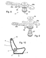
- Fig. 8
- eine perspektivische Detailansicht der Klinkenanordnung,
- Fig. 9
- eine Explosionsdarstellung der Klinkenanordnung, und
- Fig. 10
- eine schematische Seitenansicht eines Fahrzeugsitzes.
- Gemäß dem vorliegenden Ausführungsbeispiel weist ein Fahrzeugsitz 1, welcher in einer vorderen Sitzreihe verwendet wird, ein Sitzteil 3 und eine Lehne 5 auf, die relativ zum Sitzteil 3 mittels Beschlägen 7 verschwenkbar ist. Die als Getriebebeschläge ausgebildeten Beschläge 7 weisen für eine Neigungseinstellung ein Exzenterumlaufgetriebe auf und sind zusätzlich für ein Freischwenken der Lehne 5 entriegelbar. Das selbsthemmende Exzenterumlaufgetriebe ist beispielsweise für eine manuelle Neigungseinstellung in der
DE 44 36 101 A1 und für eine motorische Neigungseinstellung in derDE 199 38 666 A1 beschrieben, deren diesbezügliche Offenbarungsgehalte ausdrücklich einbezogen werden. Die für das Freischwenken verwendeten Bauteile sind in derDE 197 15 764 C2 oder derDE 102 06 299 A1 of fenbart, deren diesbezügliche Offenbarungsgehalte ausdrücklich einbezogen werden. - Beim Exzenterumlaufgetriebe stehen ein vorliegend als Zahnkranz ausgebildetes, scheibenförmiges erstes Beschlagteil 7' und ein vorliegend als Zahnrad ausgebildetes zweites Beschlagteil 7" miteinander in Getriebeverbindung und lagern zwischen sich einen Exzenter. Ein sitzteilfester Adapter ist in der Zeichnung mit dem Bezugszeichen 7a, ein Freischwenk-Beschlagteil mit dem Bezugszeichen 7b bezeichnet. Das lehnenfeste Beschlagteil 7b ist relativ zum ersten Beschlagteil 7' um eine Lehnen-Schwenkachse schwenkbar gelagert und mittels einer schwenkbar gelagerten Sperrklinke (nicht dargestellt) lösbar mit dem ersten Beschlagteil 7', beispielsweise mit einem daran angebrachten oder ausgebildeten Zahnsegment, verriegelt, während der sitzteilfeste Adapter 7a mit dem zugeordneten zweiten Beschlagteil 7" fest verbunden ist.
- Auf Grund des Exzenterumlaufgetriebes verändert sich die Position der Lehnen-Schwenkachse in Abhängigkeit der Stellung der Beschläge 7, weshalb im Folgenden auf die zwischen den Beschlägen 7 angeordnete Welle, welche sich indirekt über weitere Getriebeteile an einem sitzteilfesten Bereich des Fahrzeugsitzes 1 abstützt, der Einfachheit halber als Lehnen-Schwenkachse S Bezug genommen wird.
- Der Fahrzeugsitz 1 ist mittels zweier unten mit dem Sitzteil 3 über mehrere (nicht dargestellte) Schwingen verbundener, parallel zueinander angeordneter erster Schienen 8 und zugeordneter, fahrzeugstrukturfester, zweiter Schienen (nicht dargestellt), welche mit den ersten Schienen 8 durch wechselseitiges Umgreifen zusammenwirken, auf an sich bekannte Weise in Längsrichtung des Fahrzeugs verschiebbar am Boden angebracht. Der Verstellweg ist für den normalen Gebrauch über einen Anschlag nach vom begrenzt. Die Längseinstellbarkeit des Fahrzeugsitzes 1 ist über eine Längseinsteller-Verstelleinrichtung mit einem Bügel 9 als Bedienelement zum Betätigen der Schienenentriegelung von Hand möglich. Es kann jedoch alternativ oder in Verbindung hiermit eine motorische Längseinstellbarkeit vorgesehen sein.
- Die Lehnenneigung im Winkelbereich der normalen Benutzungsstellung, in welchem der Fahrzeugsitz 1 dem Sitzgebrauch dient, ist vorliegend über einen Motor 13 (siehe
Fig. 1 ) elektrisch betätigt einstellbar, wobei der Motor 13 lehnenfest angeordnet ist und auf an sich bekannte Weise mit der Welle und den Beschlägen 7 in Getriebeeingriff steht und mit diesen zusammenwirkt, so dass die Lehne 5 gegenüber dem Sitzteil 3 innerhalb des vorgegebenen Winkelbereichs verschwenkbar ist. Als "Endanschläge" zur Begrenzung des normalen Schwenkbereichs der Lehne 5 für die Benutzungsstellungen dienen hierbei Mikroschalter, um das bekannte Problem beim Freischwenken aus der vordersten Benutzungsstellung heraus zu umgehen, dass die freischwenkende Lehne 5 den Motor 13 mitnimmt, während ein mechanischer, fester Endanschlag mittels des Exzenterumlaufgetriebes die mit dem Motor 13 in Getriebeeingriff stehende Welle festhält, was in Verbindung mit einer Selbsthemmung des Motors 13 zu einer Beschädigung desselben führen würde. - Ferner lässt sich die Lehne 5 über eine Freischwenk-Bedieneinrichtung 15, die am oberen seitlichen Ende der Lehne 5 angeordnet ist, freischwenken, d.h. aus ihrer verriegelten, normalen Benutzungsstellung lösen und nach vom schwenken. Die Lehne 5 des Fahrzeugsitzes 1 wird hierbei manuell - in Verbindung mit einem Vorfahren des Fahrzeugsitzes 1 - in die "Easy-Entry-Stellung" gebracht, in welcher die Lehne 5 unter Vorschwenken dichtest möglich am Armaturenbrett oder am Fahrzeugsitz der vorhergehenden Sitzreihe positioniert ist, um einen möglichst großen Ein- bzw. Ausstiegsbereich für den dahinter angeordneten Fahrzeugsitz zur Verfügung stellen zu können, wenn dieser Fahrzeugsitz nicht über eine eigene Fahrzeugtüre zugänglich ist.
- Der Ablauf eines Entriegelungsvorgangs im Normalfall ist in den
Figuren 3 bis 6 dargestellt.Fig. 3 zeigt hierbei die normale Benutzungsstellung mit verriegelter Lehne 5. Hierbei ist die Lehne 5 über die selbsthemmende Getriebeanordnung der Beschläge 7 starr mit dem Sitzteil 3 verbunden.Fig. 4 zeigt den Zustand, bei welchem die Freischwenk-Bedieneinrichtung 15 am oberen Ende der Lehne 5 betätigt ist und die Verriegelung zwischen erstem Beschlagteil 7' und lehnenfestem Beschlagteil 7b gelöst wird, d.h. die Sperrklinke am Freischwenk-Beschlagteil 7b entsichert und geöffnet wird, so dass die Lehne 5 nach vom geschwenkt werden kann.Fig. 5 zeigt eine Zwischenstellung beim Freischwenken der Lehne 5 undFig. 6 zeigt die vorderste Stellung der Lehne 5 beim Freischwenken, wobei für ein Einnehmen der "Easy-Entry-Stellung" des Fahrzeugsitzes 1 die entsprechende "Easy-Entry-Betätigungsvorrichtung" aktiviert ist. - Im Folgenden werden anhand des in den
Fig. 3 bis 6 dargestellten Ablaufs die einzelnen für die Funktion relevanten Bauteile kurz beschrieben. - Zum Freischwenken der Lehne 5 wird besagte Freischwenk-Bedieneinrichtung 15 am oberen Ende der Lehne 5 betätigt, wodurch ein in der Lehne 5 verlaufender Bowdenzug 17 betätigt wird, d.h. die Hülle sich relativ zur Seele bewegt. In an sich bekannter Weise (siehe
DE 197 15 764 C2 ) wird durch die Betätigung des Bowdenzugs 17 ein Entriegelungsbolzen 19, welcher exzentrisch auf einem am Freischwenk-Beschlagteil 7b schwenkbar gelagerten, die Sperrklinke sichernden Steuerhebel sitzt, entlang einer Kulisse bewegt, wodurch ein Entriegeln der Getriebebeschläge 7, d.h. des ersten Beschlagteils 7' und des Freischwenk-Beschlagteils 7b, bewirkt wird, so dass die Lehne 5 nach vom geschwenkt werden kann. - Mit dem Entriegelungsbolzen 19 steht ferner eine ebenfalls am Freischwenk-Beschlagteil 7b schwenkbar gelagerte Klinkenanordnung 21 zur Steuerung der Schienenentriegelung für das Einnehmen der "Easy-Entry-Stellung" in Verbindung. Die Klinkenanordnung 21 weist einen um eine Klinken-Schwenkachse 23 verschwenkbar angeordneten Hebel 25 auf, welcher zweiteilig ausgebildet ist und dessen beide Teile in nachfolgend beschriebener Weise zusammenwirken. Der auf der Seite des Entriegelungsbolzens 19 angeordnete, erste Teil 25a des Hebels 25 weist am äußeren Ende ein Langloch auf, in welches der Entriegelungsbolzen 19 eingreift und die Mitnahme des Hebels 25 sichert. Das andere Ende dieses Teils des Hebels 25 weist eine kreisförmige Öffnung auf, durch welche ein die Klinken-Schwenkachse 23 bildender, am Freischwenk-Beschlagteil 7b angeordneter, mehrstufiger Lagerbolzen 27 ragt. Der Lagerbolzen 27 ist mittels Schneidnieten mit dem Beschlagteil 7b fest verbunden. Der erste Teil 25a des Hebels 25 ist derart ausgebildet, dass das Ende mit der Öffnung in einer anderen Ebene angeordnet ist als der weitere Verlauf des Hebels (siehe
Fig. 9 ). Auf einer benachbarten Stufe des Lagerbolzens 27 sitzt der ebenfalls mit einer kreisförmigen Öffnung, jedoch mit geringerem Durchmesser als der erste Teil 25a, versehene zweite Teil 25b des Hebels 25. Ein erstes Ende steht in gleicher Richtung wie der erste Teil 25a des Hebels 25 über und ist - auf Grund der versetzten Ausgestaltung des ersten Teils 25a - mit einer Seitenfläche des ersten Teils 25a in Anlage, wobei eine Feder 29 die beiden Teile 25a, 25b, wenn keine oder nur eine geringe äußere Kraft auf den Hebel 25 einwirkt, in Anlage aneinander hält. Die Feder 29 liegt mit ihrem ersten, um 90° umgebogenen Ende 29a von außen her in Anlage an den zweiten Teil 25b des Hebels (sieheFig. 8 ) an dem sich in Richtung des ersten Teils des Hebels erstreckenden Ende, jedoch auf der vom ersten Teil abgewandten Seite, an. Sie ist mit ihrem zentralen Bereich um den Lagerbolzen 27 in einer Stufe benachbart des ersten Teils 25a des Hebels gewickelt. Das andere, ebenfalls um 90° umgebogenen Ende liegt von der anderen Seite her an den ersten Teil 25a des Hebels an, so dass die beiden Teile 25a, 25b federnd in Anlage aneinander gedrückt werden. Das zweite Ende des zweiten Teils 25b steht - ausgehend vom Lagerbolzen 27 - in entgegengesetzter Richtung um etwa die gleiche Länge wie das erste Ende über und ist mit einem hakenförmigen Endbereich 31 ausgebildet, welcher als Klinke in Verbindung mit einer von einem Betätigungsring 33 vorstehenden Hakennase 33a dient. Der Betätigungsring 33 ist drehbar am ersten Beschlagteil des Beschlags 7 gelagert und und damit auch drehbar zum sitzteilfesten Adapter 7a. Die Feder 29 und beide Teile 25a, 25b des Hebels 25 werden mittels einer aufgepressten Lochscheibe 35 auf dem Lagerbolzen 27 gehalten. - Der in Folge der Betätigung der Freischwenk-Bedieneinrichtung 15 sich bewegende Entriegelungsbolzen 19, welcher durch das Langloch im ersten Teil 25a des Hebels 25 ragt, nimmt den ersten Teil 25a des Hebels 25 mit. Durch die elastische Kraft, d.h. die vorspannende Kraft der Feder 29, nimmt der erste Teil 25a des Hebels 25 den zweiten Teil 25b des Hebels 25 bei seiner Bewegung mit. Während der Bewegung des Entriegelungsbolzens 19 dreht sich der hakenförmige Endbereich 31 des Hebels 25 so weit, dass er am Betätigungsring 33 an dessen Außenumfang aufsitzt (siehe
Fig. 4 ). - Durch das nun erfolgende Vorschwenken der Lehne 5 wird der Hebel 25 mitgenommen und gleitet am Außenumfang des Betätigungsrings 33 entlang, bis er in Anlage an die Hakennase 33a gelangt (siehe
Fig. 5 ). Der bezüglich des ersten Beschlagteils 7' drehbar ausgebildete Betätigungsring 33 wird nunmehr mit der Schwenkbewegung der Lehne 5 über den Hebel 25 mitgenommen, d.h. der Betätigungsring 33 dreht sich um die Lehnen-Schwenkachse S. - Kurz vor Erreichen ihrer vordersten Schwenkposition der Lehne 5, die in
Fig. 6 dargestellt ist, wird auf an sich bekannte Weise über den mitgenommenen Betätigungsring 33 ein weiterer Bowdenzug 37, im Folgenden auf Grund seiner Funktion auch als Schienenentriegelungs-Bowdenzug 37 bezeichnet, betätigt, wofür die Seele des Bowdenzugs 37 an einem vorstehenden Bereich des Betätigungsrings 33 angebracht ist. Durch die Betätigung des Bowdenzugs 37 werden die Schienen entriegelt, so dass der Fahrzeugsitz 1 in seine vorderste Position verfahren werden kann. Somit ist ausgehend vom Entriegelungsbolzen 19 über den am mehrstufigen Lagerbolzen 27 gelagerten Hebel 25 mit seinem hakenförmigen Bereich 31 und seiner Feder 29, den Betätigungsring 33 mit seiner Hakennase 33a und den Bowdenzug 37 zur Schienenentriegelung eine Koppelvorrichtung 39 vorgesehen, welche - vorliegend verzögert - die Schienenentriegelung mit der vorhergehenden Entriegelung der Beschläge 7 für ein Freischwenken der Lehne 5 koppelt. Hierbei ist eine gemeinsame Betätigung über die Freischwenk-Bedieneinrichtung 15 vorgesehen, der Kraftfluss verzweigt sich jedoch am Entriegelungsbolzen 19, um auf vorteilhafte Weise die Bewegung der Lehne 5 für die Betätigung der Schienenentriegelung ausnutzen zu können und gleichzeitig sicherzustellen, dass vor einem Verfahren des Fahrzeugsitzes 1 die Lehne 5 weitgehend vorgeschwenkt ist. - Durch die oben beschriebene Ausgestaltung ist auch eine Entkopplung der Freischwenkfunktion der Lehne 5 samt Entriegelung der Schienen für ein Einnehmen der "Easy-Entry-Stellung" und des Einstellens der Lehnenneigung (mittels des Exzenterumlaufgetriebes) möglich. Die Entkopplung ergibt sich dadurch, dass der Hebel 25 während der Einstellung der Lehnenneigung nicht auf dem Betätigungsring 33 aufsitzt. Der am ersten Beschlagteil 7' drehbar gelagerte Betätigungsring 33 wird zwar durch den Schienenentriegelungs-Bowdenzug 37 am sitzteilfesten Adapter 7a festgehalten, jedoch können sich das erste Beschlagteil 7' und das damit verriegelte Freischwenk-Beschlagteil 7b aufgrund des nicht-aufsitzenden Hebels 25 ungehindert relativ zum Betätigungsring 33 bewegen.
- Bei dieser Anordnung tritt jedoch im sehr seltenen aber aus Sicherheitsgründen wesentlichen Fall eines Versagens des Mikroschalters zur Begrenzung des Lehnenneigungseinstellbereichs nach vom das in
Fig. 7 dargestellte Problem auf, nämlich, dass bei Betätigung der Freischwenk-Bedieneinrichtung 15, durch welche der Entriegelungsbolzen 19 bewegt wird, der hakenförmige Endbereich 31 an der falschen Stelle in Anlage an der Betätigungsring 33 gelangt, nämlich im Rückenbereich der Hakennase 33a, so dass bei einem einstückig, starr ausgebildeten Hebel 25 ein Weiterbewegen des Entriegelungsbolzens 19 und damit ein vollständiges Entriegeln und Freischwenken der Lehne 5 blockiert wäre. Das gleiche Problem kann bei manueller Lehnenneigungseinstellung auftreten, wenn über eine vorderste Winkelstellung hinaus eingestellt wird. Durch die vorliegend zweiteilige Ausgestaltung des Hebels 25 in Verbindung mit der Feder 29 kann der Hebel 25 ausknicken, so dass trotz der Anlage des hakenförmigen Endbereichs 31 an den Rückenbereich der Hakennase 33a eine vollständige Bewegung des Entriegelungsbolzens 19 erfolgen kann. Damit kann das Entriegeln von lehnenfestem Beschlagteil 7b und erstem Beschlagteil 7' und somit ein Freischwenken der Lehne 5 sichergestellt werden, beispielsweise um im Crashfall einen Insassen vom dahinter angeordneten Fahrzeugsitz zu bergen. Jedoch ist - mangels Eingreifens des hakenförmigen Endbereichs 31 in die Hakennase 33a - ein gleichzeitiges automatisches Entriegeln der Schienenentriegelung in diesem Fehlbedienungsfall vorliegend nicht möglich, aber der Fahrzeugsitz 1 kann über den Bügel 9 wie im Falle einer Veränderung der Längseinstellung des Fahrzeugsitzes verstellt werden. Durch das Vorsehen der Feder 29 und ihrer als Rückstellkraft wirkenden elastischen Kraft wird der zweiteilige Hebel 25 bei einem Zurückschwenken der Lehne 5 wieder in die normale Ausrichtung gebracht, so dass der in Richtung des Entriegelungsbolzens 19 überstehende Teil des ersten Teils 25a des Hebels wieder am zweiten Teil 25b anliegt, wie in denFig. 3 bis 6 dargestellt. - Der Hebel 25 kann gemäß einer nicht in der Zeichnung dargestellten Variante auch einstückig ausgebildet sein, wobei die beiden in diesem Fall miteinander verbunden ausgebildeten Teile 25a, 25b des Hebels derart ausgestaltet sind, dass ein Abknicken in einer Richtung möglich ist, während bei einer Belastung in entgegengesetzter Richtung der Hebel starr ausgebildet ist. Dies kann beispielsweise durch einen die Feder 29 ersetzenden Federbereich (elastischen Bereich) realisiert werden, welcher - unter Aufbau einer elastischen Kraft als Rückstellkraft - in einer Richtung gebogen werden kann, und welchem auf der gegenüberliegenden Seite benachbart ein Anschlagsbereich angeordnet ist, an welchen der Federbereich bei einer entsprechenden Belastung anliegen kann, so dass sich insgesamt die gleiche Funktion wie beim zuvor beschriebenen Ausführungsbeispiel ergibt.
- Obwohl die vorliegende Erfindung vorstehend anhand einer elektischen Lehnenneigungseinstellung beschrieben ist, kann eine entsprechende Anordnung samt Hebel 25 auch für eine mechanische Lehnenneigungseinstellung verwendet werden.
Bezugszeichenliste 1 Fahrzeugsitz 3 Sitzteil 5 Lehne 7 Beschlag 7' erstes Beschlagteil 7" zweites Beschlagteil 7a sitzteilfester Adapter 7b Freischwenk-Beschlagteil 8 erste Schiene 9 Bügel 13 Motor 15 Freischwenk-Bedieneinrichtung 17 Bowdenzug 19 Entriegelungsbolzen 21 Klinkenanordnung 23 Klinken-Schwenkachse 25 Hebel 25a erster Teil (Hebel) 25b zweiter Teil (Hebel) 27 Lagerbolzen 29 Feder 29a erstes Ende 31 hakenförmiger Endbereich 33 Betätigungsring 33a Hakennase 35 Lochscheibe 37 Bowdenzug (Schienenentriegelung) 39 Koppelvorrichtung S Schwenkachse (Lehne)
Claims (13)
- Fahrzeugsitz mit einer neigungseinstellbaren und freischwenkbaren Lehne (5), insbesondere mit elektromotorischer Lehnenneigungseinstellung, der eine "Easy-Entry-Stellung" einnehmen kann, bei welcher der längseinstellbare Fahrzeugsitz (1) in einer vorderen Position angeordnet und die freigeschwenkte Lehne (5) nach vorn geschwenkt ist, einer Lehnenentriegelung für ein Entriegeln der Lehne (5) zum Freischwenken, einer Schienenentriegelung für ein Einstellen der Längsposition des Fahrzeugsitzes (1) und einer Koppelvorrichtung (39) zum Koppeln der Betätigung der Lehnenentriegelung und der Schienenentriegelung für ein Einnehmen der "Easy-Entry-Stellung", wobei Teil der Koppelvorrichtung (39) eine Klinkenanordnung (21) ist, welche einen um eine Achse verschwenkbar angeordneten Hebel (25) aufweist, der zwei relativ zueinander in ihrer Position veränderbare Bereiche hat, dadurch gekennzeichnet, dass die beiden Bereiche relativ zueinander um die gleiche Achse verschwenkbar sind wie der Hebel (25).
- Fahrzeugsitz nach Anspruch 1, dadurch gekennzeichnet, dass die Relativbewegung der beiden Bereiche des Hebels (25) in einer Richtung durch eine Anlagefläche räumlich begrenzt ist.
- Fahrzeugsitz nach einem der vorhergehenden Ansprüche, dadurch gekennzeichnet, dass die Relativbewegung der beiden Bereiche des Hebels (25) in einer Richtung durch eine elastische Kraft begrenzt ist, welche als Rückstellkraft wirkt.
- Fahrzeugsitz nach Anspruch 2 und 3, dadurch gekennzeichnet, dass die elastische Kraft auf die beiden Bereiche des Hebels (25) derart wirkt, dass der erste Bereich des Hebels in Anlage an den zweiten Bereich des Hebels gedrückt wird.
- Fahrzeugsitz nach Anspruch 3 oder 4, dadurch gekennzeichnet, dass die elastische Kraft durch eine Feder (29) oder durch einen elastischen Bereich des Hebels (25) aufbaut wird.
- Fahrzeugsitz nach einem der vorhergehenden Ansprüche, dadurch gekennzeichnet, dass der Hebel (25) zweiteilig ausgebildet ist, wobei die beiden Teile (25a, 25b) auf einer gemeinsamen Achse verschwenkbar angeordnet sind, und dass eine Feder (29) vorgesehen ist, welche die beiden Teile (25a, 25b) im Normalbetrieb in Anlage aneinander drückt.
- Fahrzeugsitz nach einem der vorhergehenden Ansprüche, dadurch gekennzeichnet, dass der Hebel (25) an einem Ende einen hakenförmigen Bereich (31) aufweist, welcher mit einer Hakennase (33a) eines drehbar gelagerten Betätigungsrings (33) zusammenwirken kann.
- Fahrzeugsitz nach Anspruch 7, dadurch gekennzeichnet, dass die mögliche Relativbewegung der beiden Bereiche des Hebels (25) in Öffnungsrichtung des hakenförmigen Bereichs (31) gerichtet ist.
- Fahrzeugsitz nach einem der vorhergehenden Ansprüche, dadurch gekennzeichnet, dass der Hebel (25) an einem ersten Ende eine Öffnung, insbesondere ein Langloch, aufweist, in welche ein Entriegelungsbolzen (19) ragt, der über eine Freischwenk-Bedieneinrichtung (15) bewegbar ist.
- Fahrzeugsitz nach einem der vorhergehenden Ansprüche, dadurch gekennzeichnet, dass der Hebel (25) an einem zweiten Ende einen hakenförmigen Endbereich (31) aufweist, welcher mit einem Betätigungsring (33) zusammenwirken kann, um durch ein Eingreifen des hakenförmigen Endbereichs (31) in eine Hakennase (33a) des Betätigungsrings (33) und das weitere Verschwenken der Lehne (5) des Fahrzeugsitzes (1) eine Drehung des Betätigungsrings (33) zu bewirken und damit die Schienenentriegelung zu lösen, so dass der Fahrzeugsitz (1) nach vom in die "Easy-Entry-Stellung" verschiebbar ist.
- Fahrzeugsitz nach einem der vorhergehenden Ansprüche, dadurch gekennzeichnet, dass die Lehne (5) mittels wenigstens eines Beschlags (7) relativ zu einem Sitzteil (3) des Fahrzeugsitzes (1) neigungseinstellbar und freischwenkbar ist, wobei der Hebel (25) und ein mit dem Hebel (25) zusammenwirkenden Teil der Koppelvorrichtung (39) an zwei verschiedenen Beschlagteilen (7', 7b) des Beschlags (7) angeordnet sind.
- Fahrzeugsitz nach einem der vorhergehenden Ansprüche, dadurch gekennzeichnet, dass der mit dem Hebel (25) zusammenwirkende Teil der Koppelvorrichtung ein drehbar gelagerter Betätigungsring (33) ist, der an die Schienenentriegelung gekoppelt ist und mittels dieser am sitzteilfesten Teil (7a, 7") des Beschlags (7) gehalten wird.
- Fahrzeugsitz nach einem der vorhergehenden Ansprüche, dadurch gekennzeichnet, dass der Beschlag (7) ein Getriebebeschlag mit selbsthemmendem Exzenterumlaufgetriebe ist.
Priority Applications (1)
| Application Number | Priority Date | Filing Date | Title |
|---|---|---|---|
| PL09752738T PL2352660T3 (pl) | 2008-12-01 | 2009-11-03 | Fotel pojazdu z układem zapadkowym |
Applications Claiming Priority (2)
| Application Number | Priority Date | Filing Date | Title |
|---|---|---|---|
| DE102008061037A DE102008061037B3 (de) | 2008-12-01 | 2008-12-01 | Fahrzeugsitz mit Klinkenanordnung |
| PCT/EP2009/007849 WO2010063351A1 (de) | 2008-12-01 | 2009-11-03 | Fahrzeugsitz mit klinkenanordnung |
Publications (2)
| Publication Number | Publication Date |
|---|---|
| EP2352660A1 EP2352660A1 (de) | 2011-08-10 |
| EP2352660B1 true EP2352660B1 (de) | 2013-07-17 |
Family
ID=41796437
Family Applications (1)
| Application Number | Title | Priority Date | Filing Date |
|---|---|---|---|
| EP09752738.6A Active EP2352660B1 (de) | 2008-12-01 | 2009-11-03 | Fahrzeugsitz mit klinkenanordnung |
Country Status (6)
| Country | Link |
|---|---|
| EP (1) | EP2352660B1 (de) |
| CN (1) | CN102076519B (de) |
| DE (1) | DE102008061037B3 (de) |
| PL (1) | PL2352660T3 (de) |
| WO (1) | WO2010063351A1 (de) |
| ZA (1) | ZA201005911B (de) |
Cited By (2)
| Publication number | Priority date | Publication date | Assignee | Title |
|---|---|---|---|---|
| EP3915829A1 (de) | 2020-05-28 | 2021-12-01 | Faurecia Autositze GmbH | Fahrzeugsitzbeschlag und fahrzeugsitz |
| DE102022103377A1 (de) | 2022-02-14 | 2023-08-17 | Faurecia Autositze Gmbh | Fahrzeugsitzbeschlag und Fahrzeugsitz |
Families Citing this family (8)
| Publication number | Priority date | Publication date | Assignee | Title |
|---|---|---|---|---|
| DE102011105360A1 (de) | 2011-06-21 | 2012-12-27 | Keiper Gmbh & Co. Kg | Fahrzeugsitz, insbesondere Kraftfahrzeugsitz |
| DE102011052059B4 (de) | 2011-07-22 | 2021-07-22 | Adient Luxembourg Holding S.À R.L. | Sitzbeschlag für einen Kraftfahrzeugsitz |
| DE102013217226B4 (de) | 2013-02-18 | 2018-10-31 | Adient Luxembourg Holding S.À R.L. | Fahrzeugsitz, insbesondere für eine hintere sitzreihe |
| DE102013207027B4 (de) * | 2013-04-18 | 2020-01-23 | Brose Fahrzeugteile Gmbh & Co. Kommanditgesellschaft, Coburg | Fahrzeugsitz, Verfahren zur Montage eines Fahrzeugsitzes und Sitzbeschlag |
| DE102015201362B4 (de) | 2015-01-27 | 2016-10-06 | Johnson Controls Components Gmbh & Co. Kg | Fahrzeugsitz, insbesondere Kraftfahrzeugsitz, mit Koppelvorrichtung |
| CN105416113B (zh) * | 2015-12-17 | 2017-10-03 | 辽宁工业大学 | 一种儿童智能座椅及控制方法 |
| US10076975B2 (en) * | 2016-08-11 | 2018-09-18 | Goodrich Corporation | Brake release for aircraft seat |
| DE102017218125A1 (de) * | 2017-10-11 | 2019-04-11 | Volkswagen Aktiengesellschaft | Fahrzeugsitz mit einem Easy-Entry-Mechanismus |
Family Cites Families (11)
| Publication number | Priority date | Publication date | Assignee | Title |
|---|---|---|---|---|
| DE4436101C5 (de) * | 1993-11-30 | 2008-12-11 | Keiper Gmbh & Co.Kg | Lehneneinstellbeschlag für Sitze mit verstellbarer Rückenlehne, insbesondere Kraftfahrzeugsitze |
| DE19715764C2 (de) * | 1997-04-16 | 2000-01-27 | Keiper Gmbh & Co | Neigungseinstellbeschlag mit Freischwenkeinrichtung für eine Rückenlehne eines Kraftfahrzeugsitzes |
| DE19938666C5 (de) * | 1999-08-14 | 2008-01-03 | Keiper Gmbh & Co.Kg | Verstellbeschlag für Sitze mit neigungseinstellbarer Lehne, insbesondere für Kraftfahzeugsitze |
| DE10206304B4 (de) * | 2002-02-11 | 2009-01-29 | Keiper Gmbh & Co.Kg | Beschlag für einen Fahrzeugsitz |
| DE10206299B4 (de) * | 2002-02-11 | 2014-05-15 | Keiper Gmbh & Co. Kg | Beschlag für einen Fahrzeugsitz sowie Fahrzeugsitz |
| DE102004061139B4 (de) * | 2004-06-22 | 2014-03-06 | C. Rob. Hammerstein Gmbh & Co. Kg | Vorverlagerbarer Kfz-Sitz, insbesondere für 2-türige Fahrzeuge |
| CN2853497Y (zh) * | 2005-11-30 | 2007-01-03 | 上海延锋江森座椅有限公司 | 方便进车系统 |
| JP4968776B2 (ja) * | 2006-08-18 | 2012-07-04 | テイ・エス テック株式会社 | 車両用シート |
| DE102007011998B4 (de) * | 2007-03-09 | 2013-08-01 | Johnson Controls Gmbh | Fahrzeugsitz mit einem Beschlag zur Neigungsverstellung und zum Freischwenken einer Lehne |
| US8146995B2 (en) * | 2007-03-09 | 2012-04-03 | Johnson Controls Technology Company | Vehicle seat with a tumbling recliner |
| WO2009103641A2 (de) * | 2008-02-22 | 2009-08-27 | C. Rob. Hammerstein Gmbh & Co. Kg | Vorverlagerbarer kraftfahrzeugsitz mit einem rückenlehnengelenkbeschlag und rücklehnengelenkbeschlag |
-
2008
- 2008-12-01 DE DE102008061037A patent/DE102008061037B3/de not_active Expired - Fee Related
-
2009
- 2009-11-03 CN CN2009801242414A patent/CN102076519B/zh active Active
- 2009-11-03 WO PCT/EP2009/007849 patent/WO2010063351A1/de active Application Filing
- 2009-11-03 EP EP09752738.6A patent/EP2352660B1/de active Active
- 2009-11-03 PL PL09752738T patent/PL2352660T3/pl unknown
-
2010
- 2010-08-18 ZA ZA2010/05911A patent/ZA201005911B/en unknown
Cited By (3)
| Publication number | Priority date | Publication date | Assignee | Title |
|---|---|---|---|---|
| EP3915829A1 (de) | 2020-05-28 | 2021-12-01 | Faurecia Autositze GmbH | Fahrzeugsitzbeschlag und fahrzeugsitz |
| DE102020114396A1 (de) | 2020-05-28 | 2021-12-02 | Faurecia Autositze Gmbh | Fahrzeugsitzbeschlag und Fahrzeugsitz |
| DE102022103377A1 (de) | 2022-02-14 | 2023-08-17 | Faurecia Autositze Gmbh | Fahrzeugsitzbeschlag und Fahrzeugsitz |
Also Published As
| Publication number | Publication date |
|---|---|
| CN102076519A (zh) | 2011-05-25 |
| EP2352660A1 (de) | 2011-08-10 |
| PL2352660T3 (pl) | 2013-12-31 |
| CN102076519B (zh) | 2013-05-29 |
| ZA201005911B (en) | 2011-10-26 |
| DE102008061037B3 (de) | 2010-05-06 |
| WO2010063351A1 (de) | 2010-06-10 |
Similar Documents
| Publication | Publication Date | Title |
|---|---|---|
| EP2352660B1 (de) | Fahrzeugsitz mit klinkenanordnung | |
| EP3102841B1 (de) | Fahrzeugsitz, insbesondere kraftfahrzeugsitz | |
| EP1976723B1 (de) | Beschlag für einen fahrzeugsitz | |
| EP2240342B1 (de) | Beschlag für einen fahrzeugsitz | |
| EP2726324B1 (de) | Beschlagsystem für einen fahrzeugsitz | |
| EP2057033B1 (de) | Verriegelungsvorrichtung für einen fahrzeugsitz | |
| EP2755853B1 (de) | Beschlagsystem für einen fahrzeugsitz | |
| EP3325310B1 (de) | Fahrzeugsitz | |
| WO2015059053A1 (de) | Elektrisch betriebener lehnenversteller und fahrzeugsitz mit einem solchen lehnenversteller | |
| EP1776253A2 (de) | Vorrichtung für ein fahrzeug zur selbsttätigen arretierung einer komponente, insbesondere ein fahrzeugsitz, und fahrzeugsitz | |
| DE3038912A1 (de) | Gelenkbeschlag fuer fahrzeugsitze mit einer neigungseinstellbaren rueckenlehne | |
| DE102009029858A1 (de) | Baugruppe mit Rastbeschlag und Freischwenkmechanik | |
| WO2016142366A1 (de) | Fahrzeugsitz mit easy-entry-funktion | |
| DE102017219708B4 (de) | Fahrzeugsitz | |
| WO2003024739A1 (de) | Kraftfahrzeugsitz | |
| DE102022103377A1 (de) | Fahrzeugsitzbeschlag und Fahrzeugsitz | |
| DE102009022979B3 (de) | Längseinsteller für einen Fahrzeugsitz | |
| DE3333056C2 (de) | ||
| WO2017216053A1 (de) | Längseinsteller für einen fahrzeugsitz und fahrzeugsitz | |
| EP3290261A1 (de) | Längseinsteller für einen fahrzeugsitz und fahrzeugsitz | |
| DE102005040629B4 (de) | Beschlag für einen Fahrzeugsitz | |
| DE102007030545B3 (de) | Beschlag für einen Fahrzeugsitz | |
| EP3162618B1 (de) | Längseinsteller für einen fahrzeugsitz, fahrzeugsitz | |
| EP3290260B1 (de) | Längseinsteller für einen fahrzeugsitz und fahrzeugsitz | |
| EP3290259B1 (de) | Längseinsteller für einen fahrzeugsitz und fahrzeugsitz |
Legal Events
| Date | Code | Title | Description |
|---|---|---|---|
| PUAI | Public reference made under article 153(3) epc to a published international application that has entered the european phase |
Free format text: ORIGINAL CODE: 0009012 |
|
| 17P | Request for examination filed |
Effective date: 20100722 |
|
| AK | Designated contracting states |
Kind code of ref document: A1 Designated state(s): AT BE BG CH CY CZ DE DK EE ES FI FR GB GR HR HU IE IS IT LI LT LU LV MC MK MT NL NO PL PT RO SE SI SK SM TR |
|
| DAX | Request for extension of the european patent (deleted) | ||
| GRAP | Despatch of communication of intention to grant a patent |
Free format text: ORIGINAL CODE: EPIDOSNIGR1 |
|
| INTG | Intention to grant announced |
Effective date: 20130417 |
|
| GRAS | Grant fee paid |
Free format text: ORIGINAL CODE: EPIDOSNIGR3 |
|
| GRAA | (expected) grant |
Free format text: ORIGINAL CODE: 0009210 |
|
| AK | Designated contracting states |
Kind code of ref document: B1 Designated state(s): AT BE BG CH CY CZ DE DK EE ES FI FR GB GR HR HU IE IS IT LI LT LU LV MC MK MT NL NO PL PT RO SE SI SK SM TR |
|
| REG | Reference to a national code |
Ref country code: GB Ref legal event code: FG4D Free format text: NOT ENGLISH |
|
| REG | Reference to a national code |
Ref country code: CH Ref legal event code: EP |
|
| REG | Reference to a national code |
Ref country code: IE Ref legal event code: FG4D Free format text: LANGUAGE OF EP DOCUMENT: GERMAN |
|
| REG | Reference to a national code |
Ref country code: AT Ref legal event code: REF Ref document number: 621967 Country of ref document: AT Kind code of ref document: T Effective date: 20130815 |
|
| REG | Reference to a national code |
Ref country code: DE Ref legal event code: R096 Ref document number: 502009007606 Country of ref document: DE Effective date: 20130912 |
|
| REG | Reference to a national code |
Ref country code: SK Ref legal event code: T3 Ref document number: E 14833 Country of ref document: SK |
|
| REG | Reference to a national code |
Ref country code: NL Ref legal event code: VDEP Effective date: 20130717 |
|
| REG | Reference to a national code |
Ref country code: LT Ref legal event code: MG4D |
|
| REG | Reference to a national code |
Ref country code: PL Ref legal event code: T3 |
|
| PG25 | Lapsed in a contracting state [announced via postgrant information from national office to epo] |
Ref country code: CY Free format text: LAPSE BECAUSE OF FAILURE TO SUBMIT A TRANSLATION OF THE DESCRIPTION OR TO PAY THE FEE WITHIN THE PRESCRIBED TIME-LIMIT Effective date: 20130626 Ref country code: PT Free format text: LAPSE BECAUSE OF FAILURE TO SUBMIT A TRANSLATION OF THE DESCRIPTION OR TO PAY THE FEE WITHIN THE PRESCRIBED TIME-LIMIT Effective date: 20131118 Ref country code: LT Free format text: LAPSE BECAUSE OF FAILURE TO SUBMIT A TRANSLATION OF THE DESCRIPTION OR TO PAY THE FEE WITHIN THE PRESCRIBED TIME-LIMIT Effective date: 20130717 Ref country code: SE Free format text: LAPSE BECAUSE OF FAILURE TO SUBMIT A TRANSLATION OF THE DESCRIPTION OR TO PAY THE FEE WITHIN THE PRESCRIBED TIME-LIMIT Effective date: 20130717 Ref country code: NO Free format text: LAPSE BECAUSE OF FAILURE TO SUBMIT A TRANSLATION OF THE DESCRIPTION OR TO PAY THE FEE WITHIN THE PRESCRIBED TIME-LIMIT Effective date: 20131017 Ref country code: IS Free format text: LAPSE BECAUSE OF FAILURE TO SUBMIT A TRANSLATION OF THE DESCRIPTION OR TO PAY THE FEE WITHIN THE PRESCRIBED TIME-LIMIT Effective date: 20131117 Ref country code: HR Free format text: LAPSE BECAUSE OF FAILURE TO SUBMIT A TRANSLATION OF THE DESCRIPTION OR TO PAY THE FEE WITHIN THE PRESCRIBED TIME-LIMIT Effective date: 20130717 |
|
| PG25 | Lapsed in a contracting state [announced via postgrant information from national office to epo] |
Ref country code: FI Free format text: LAPSE BECAUSE OF FAILURE TO SUBMIT A TRANSLATION OF THE DESCRIPTION OR TO PAY THE FEE WITHIN THE PRESCRIBED TIME-LIMIT Effective date: 20130717 Ref country code: SI Free format text: LAPSE BECAUSE OF FAILURE TO SUBMIT A TRANSLATION OF THE DESCRIPTION OR TO PAY THE FEE WITHIN THE PRESCRIBED TIME-LIMIT Effective date: 20130717 Ref country code: LV Free format text: LAPSE BECAUSE OF FAILURE TO SUBMIT A TRANSLATION OF THE DESCRIPTION OR TO PAY THE FEE WITHIN THE PRESCRIBED TIME-LIMIT Effective date: 20130717 Ref country code: GR Free format text: LAPSE BECAUSE OF FAILURE TO SUBMIT A TRANSLATION OF THE DESCRIPTION OR TO PAY THE FEE WITHIN THE PRESCRIBED TIME-LIMIT Effective date: 20131018 Ref country code: ES Free format text: LAPSE BECAUSE OF FAILURE TO SUBMIT A TRANSLATION OF THE DESCRIPTION OR TO PAY THE FEE WITHIN THE PRESCRIBED TIME-LIMIT Effective date: 20131028 Ref country code: NL Free format text: LAPSE BECAUSE OF FAILURE TO SUBMIT A TRANSLATION OF THE DESCRIPTION OR TO PAY THE FEE WITHIN THE PRESCRIBED TIME-LIMIT Effective date: 20130717 |
|
| PG25 | Lapsed in a contracting state [announced via postgrant information from national office to epo] |
Ref country code: CY Free format text: LAPSE BECAUSE OF FAILURE TO SUBMIT A TRANSLATION OF THE DESCRIPTION OR TO PAY THE FEE WITHIN THE PRESCRIBED TIME-LIMIT Effective date: 20130717 |
|
| PG25 | Lapsed in a contracting state [announced via postgrant information from national office to epo] |
Ref country code: RO Free format text: LAPSE BECAUSE OF FAILURE TO SUBMIT A TRANSLATION OF THE DESCRIPTION OR TO PAY THE FEE WITHIN THE PRESCRIBED TIME-LIMIT Effective date: 20130717 Ref country code: DK Free format text: LAPSE BECAUSE OF FAILURE TO SUBMIT A TRANSLATION OF THE DESCRIPTION OR TO PAY THE FEE WITHIN THE PRESCRIBED TIME-LIMIT Effective date: 20130717 Ref country code: EE Free format text: LAPSE BECAUSE OF FAILURE TO SUBMIT A TRANSLATION OF THE DESCRIPTION OR TO PAY THE FEE WITHIN THE PRESCRIBED TIME-LIMIT Effective date: 20130717 |
|
| PLBE | No opposition filed within time limit |
Free format text: ORIGINAL CODE: 0009261 |
|
| STAA | Information on the status of an ep patent application or granted ep patent |
Free format text: STATUS: NO OPPOSITION FILED WITHIN TIME LIMIT |
|
| PG25 | Lapsed in a contracting state [announced via postgrant information from national office to epo] |
Ref country code: IT Free format text: LAPSE BECAUSE OF FAILURE TO SUBMIT A TRANSLATION OF THE DESCRIPTION OR TO PAY THE FEE WITHIN THE PRESCRIBED TIME-LIMIT Effective date: 20130717 |
|
| BERE | Be: lapsed |
Owner name: KEIPER G.M.B.H. & CO. KG Effective date: 20131130 |
|
| 26N | No opposition filed |
Effective date: 20140422 |
|
| REG | Reference to a national code |
Ref country code: CH Ref legal event code: PL |
|
| GBPC | Gb: european patent ceased through non-payment of renewal fee |
Effective date: 20131103 |
|
| PG25 | Lapsed in a contracting state [announced via postgrant information from national office to epo] |
Ref country code: CH Free format text: LAPSE BECAUSE OF NON-PAYMENT OF DUE FEES Effective date: 20131130 Ref country code: MC Free format text: LAPSE BECAUSE OF FAILURE TO SUBMIT A TRANSLATION OF THE DESCRIPTION OR TO PAY THE FEE WITHIN THE PRESCRIBED TIME-LIMIT Effective date: 20130717 Ref country code: LI Free format text: LAPSE BECAUSE OF NON-PAYMENT OF DUE FEES Effective date: 20131130 |
|
| REG | Reference to a national code |
Ref country code: DE Ref legal event code: R097 Ref document number: 502009007606 Country of ref document: DE Effective date: 20140422 |
|
| REG | Reference to a national code |
Ref country code: DE Ref legal event code: R081 Ref document number: 502009007606 Country of ref document: DE Owner name: ADIENT LUXEMBOURG HOLDING S.A R.L., LU Free format text: FORMER OWNER: KEIPER GMBH & CO. KG, 67657 KAISERSLAUTERN, DE Effective date: 20140710 Ref country code: DE Ref legal event code: R081 Ref document number: 502009007606 Country of ref document: DE Owner name: ADIENT LUXEMBOURG HOLDING S.A.R.L., LU Free format text: FORMER OWNER: KEIPER GMBH & CO. KG, 67657 KAISERSLAUTERN, DE Effective date: 20140710 Ref country code: DE Ref legal event code: R081 Ref document number: 502009007606 Country of ref document: DE Owner name: JOHNSON CONTROLS COMPONENTS GMBH & CO. KG, DE Free format text: FORMER OWNER: KEIPER GMBH & CO. KG, 67657 KAISERSLAUTERN, DE Effective date: 20140710 |
|
| REG | Reference to a national code |
Ref country code: IE Ref legal event code: MM4A |
|
| PG25 | Lapsed in a contracting state [announced via postgrant information from national office to epo] |
Ref country code: BE Free format text: LAPSE BECAUSE OF NON-PAYMENT OF DUE FEES Effective date: 20131130 |
|
| PG25 | Lapsed in a contracting state [announced via postgrant information from national office to epo] |
Ref country code: IE Free format text: LAPSE BECAUSE OF NON-PAYMENT OF DUE FEES Effective date: 20131103 |
|
| PG25 | Lapsed in a contracting state [announced via postgrant information from national office to epo] |
Ref country code: GB Free format text: LAPSE BECAUSE OF NON-PAYMENT OF DUE FEES Effective date: 20131103 |
|
| PG25 | Lapsed in a contracting state [announced via postgrant information from national office to epo] |
Ref country code: SM Free format text: LAPSE BECAUSE OF FAILURE TO SUBMIT A TRANSLATION OF THE DESCRIPTION OR TO PAY THE FEE WITHIN THE PRESCRIBED TIME-LIMIT Effective date: 20130717 |
|
| PG25 | Lapsed in a contracting state [announced via postgrant information from national office to epo] |
Ref country code: TR Free format text: LAPSE BECAUSE OF FAILURE TO SUBMIT A TRANSLATION OF THE DESCRIPTION OR TO PAY THE FEE WITHIN THE PRESCRIBED TIME-LIMIT Effective date: 20130717 |
|
| PG25 | Lapsed in a contracting state [announced via postgrant information from national office to epo] |
Ref country code: LU Free format text: LAPSE BECAUSE OF NON-PAYMENT OF DUE FEES Effective date: 20131103 Ref country code: BG Free format text: LAPSE BECAUSE OF FAILURE TO SUBMIT A TRANSLATION OF THE DESCRIPTION OR TO PAY THE FEE WITHIN THE PRESCRIBED TIME-LIMIT Effective date: 20130717 Ref country code: MK Free format text: LAPSE BECAUSE OF FAILURE TO SUBMIT A TRANSLATION OF THE DESCRIPTION OR TO PAY THE FEE WITHIN THE PRESCRIBED TIME-LIMIT Effective date: 20130717 Ref country code: HU Free format text: LAPSE BECAUSE OF FAILURE TO SUBMIT A TRANSLATION OF THE DESCRIPTION OR TO PAY THE FEE WITHIN THE PRESCRIBED TIME-LIMIT; INVALID AB INITIO Effective date: 20091103 |
|
| PG25 | Lapsed in a contracting state [announced via postgrant information from national office to epo] |
Ref country code: MT Free format text: LAPSE BECAUSE OF FAILURE TO SUBMIT A TRANSLATION OF THE DESCRIPTION OR TO PAY THE FEE WITHIN THE PRESCRIBED TIME-LIMIT Effective date: 20130717 |
|
| REG | Reference to a national code |
Ref country code: FR Ref legal event code: PLFP Year of fee payment: 7 |
|
| REG | Reference to a national code |
Ref country code: AT Ref legal event code: MM01 Ref document number: 621967 Country of ref document: AT Kind code of ref document: T Effective date: 20141103 |
|
| PG25 | Lapsed in a contracting state [announced via postgrant information from national office to epo] |
Ref country code: AT Free format text: LAPSE BECAUSE OF NON-PAYMENT OF DUE FEES Effective date: 20141103 |
|
| REG | Reference to a national code |
Ref country code: FR Ref legal event code: PLFP Year of fee payment: 8 |
|
| REG | Reference to a national code |
Ref country code: DE Ref legal event code: R081 Ref document number: 502009007606 Country of ref document: DE Owner name: KEIPER SEATING MECHANISMS CO., LTD., CN Free format text: FORMER OWNER: JOHNSON CONTROLS COMPONENTS GMBH & CO. KG, 67657 KAISERSLAUTERN, DE Ref country code: DE Ref legal event code: R081 Ref document number: 502009007606 Country of ref document: DE Owner name: ADIENT LUXEMBOURG HOLDING S.A R.L., LU Free format text: FORMER OWNER: JOHNSON CONTROLS COMPONENTS GMBH & CO. KG, 67657 KAISERSLAUTERN, DE Ref country code: DE Ref legal event code: R081 Ref document number: 502009007606 Country of ref document: DE Owner name: ADIENT LUXEMBOURG HOLDING S.A.R.L., LU Free format text: FORMER OWNER: JOHNSON CONTROLS COMPONENTS GMBH & CO. KG, 67657 KAISERSLAUTERN, DE |
|
| REG | Reference to a national code |
Ref country code: FR Ref legal event code: PLFP Year of fee payment: 9 |
|
| REG | Reference to a national code |
Ref country code: DE Ref legal event code: R081 Ref document number: 502009007606 Country of ref document: DE Owner name: KEIPER SEATING MECHANISMS CO., LTD., CN Free format text: FORMER OWNER: ADIENT LUXEMBOURG HOLDING S.A.R.L., LUXEMBOURG, LU Ref country code: DE Ref legal event code: R081 Ref document number: 502009007606 Country of ref document: DE Owner name: ADIENT LUXEMBOURG HOLDING S.A R.L., LU Free format text: FORMER OWNER: ADIENT LUXEMBOURG HOLDING S.A.R.L., LUXEMBOURG, LU |
|
| REG | Reference to a national code |
Ref country code: DE Ref legal event code: R082 Ref document number: 502009007606 Country of ref document: DE Representative=s name: KUTZENBERGER WOLFF & PARTNER PATENTANWALTSPART, DE Ref country code: DE Ref legal event code: R081 Ref document number: 502009007606 Country of ref document: DE Owner name: KEIPER SEATING MECHANISMS CO., LTD., CN Free format text: FORMER OWNER: ADIENT YANFENG SEATING MECHANISMS CO., LTD., SHANGHAI, CN Ref country code: DE Ref legal event code: R081 Ref document number: 502009007606 Country of ref document: DE Owner name: KEIPER SEATING MECHANISMS CO., LTD., CN Free format text: FORMER OWNER: ADIENT LUXEMBOURG HOLDING S.A R.L., LUXEMBOURG, LU Ref country code: DE Ref legal event code: R082 Ref document number: 502009007606 Country of ref document: DE Representative=s name: LIEDTKE & PARTNER PATENTANWAELTE, DE |
|
| REG | Reference to a national code |
Ref country code: SK Ref legal event code: TC4A Ref document number: E 14833 Country of ref document: SK Owner name: KEIPER SEATING MECHANISMS CO., LTD., PUDONG, S, CN Effective date: 20220211 Ref country code: SK Ref legal event code: PC4A Ref document number: E 14833 Country of ref document: SK Owner name: ADIENT YANFENG SEATING MECHANISMS CO., LTD, PU, CN Free format text: FORMER OWNER: ADIENT LUXEMBOURG HOLDING S.A R.L., LUXEMBOURG, LU Effective date: 20220211 Ref country code: SK Ref legal event code: PC4A Ref document number: E 14833 Country of ref document: SK Owner name: ADIENT LUXEMBOURG HOLDING S.A R.L., LUXEMBOURG, LU Free format text: FORMER OWNER: JOHNSON CONTROLS METALS HOLDING LTD. & CO. KG, RATINGEN, DE Effective date: 20220210 Ref country code: SK Ref legal event code: PC4A Ref document number: E 14833 Country of ref document: SK Owner name: JOHNSON CONTROLS METALS HOLDING LTD. & CO. KG,, DE Free format text: FORMER OWNER: JOHNSON CONTROLS COMPONENTS GMBH & CO. KG, BURSCHEID, DE Effective date: 20220210 |
|
| REG | Reference to a national code |
Ref country code: DE Ref legal event code: R082 Ref document number: 502009007606 Country of ref document: DE Representative=s name: KUTZENBERGER WOLFF & PARTNER PATENTANWALTSPART, DE |
|
| PGFP | Annual fee paid to national office [announced via postgrant information from national office to epo] |
Ref country code: SK Payment date: 20230926 Year of fee payment: 15 Ref country code: PL Payment date: 20230830 Year of fee payment: 15 Ref country code: FR Payment date: 20230911 Year of fee payment: 15 |
|
| PGFP | Annual fee paid to national office [announced via postgrant information from national office to epo] |
Ref country code: DE Payment date: 20230906 Year of fee payment: 15 Ref country code: CZ Payment date: 20231018 Year of fee payment: 15 |