EP2349554B1 - Réacteur à double cuve - Google Patents
Réacteur à double cuve Download PDFInfo
- Publication number
- EP2349554B1 EP2349554B1 EP09815535.1A EP09815535A EP2349554B1 EP 2349554 B1 EP2349554 B1 EP 2349554B1 EP 09815535 A EP09815535 A EP 09815535A EP 2349554 B1 EP2349554 B1 EP 2349554B1
- Authority
- EP
- European Patent Office
- Prior art keywords
- vessel
- condensable gas
- reactor
- inner vessel
- pressure
- Prior art date
- Legal status (The legal status is an assumption and is not a legal conclusion. Google has not performed a legal analysis and makes no representation as to the accuracy of the status listed.)
- Active
Links
- 230000009977 dual effect Effects 0.000 title claims description 23
- 239000007789 gas Substances 0.000 claims description 93
- 238000006243 chemical reaction Methods 0.000 claims description 62
- 239000007788 liquid Substances 0.000 claims description 45
- 238000000034 method Methods 0.000 claims description 44
- IJGRMHOSHXDMSA-UHFFFAOYSA-N Atomic nitrogen Chemical compound N#N IJGRMHOSHXDMSA-UHFFFAOYSA-N 0.000 claims description 38
- 229910052757 nitrogen Inorganic materials 0.000 claims description 19
- 238000010438 heat treatment Methods 0.000 claims description 17
- 229920001971 elastomer Polymers 0.000 claims description 12
- 229910052751 metal Inorganic materials 0.000 claims description 12
- 239000002184 metal Substances 0.000 claims description 12
- 239000000126 substance Substances 0.000 claims description 11
- 230000007797 corrosion Effects 0.000 claims description 10
- 238000005260 corrosion Methods 0.000 claims description 10
- 229910045601 alloy Inorganic materials 0.000 claims description 9
- 239000000956 alloy Substances 0.000 claims description 9
- 238000000638 solvent extraction Methods 0.000 claims description 9
- 239000000376 reactant Substances 0.000 claims description 8
- 238000000576 coating method Methods 0.000 claims description 6
- XKRFYHLGVUSROY-UHFFFAOYSA-N Argon Chemical compound [Ar] XKRFYHLGVUSROY-UHFFFAOYSA-N 0.000 claims description 4
- MWUXSHHQAYIFBG-UHFFFAOYSA-N Nitric oxide Chemical compound O=[N] MWUXSHHQAYIFBG-UHFFFAOYSA-N 0.000 claims description 4
- GQPLMRYTRLFLPF-UHFFFAOYSA-N Nitrous Oxide Chemical compound [O-][N+]#N GQPLMRYTRLFLPF-UHFFFAOYSA-N 0.000 claims description 4
- -1 ethylene propylene diene Chemical class 0.000 claims description 4
- VNWKTOKETHGBQD-UHFFFAOYSA-N methane Chemical compound C VNWKTOKETHGBQD-UHFFFAOYSA-N 0.000 claims description 4
- 239000010935 stainless steel Substances 0.000 claims description 4
- 229910001220 stainless steel Inorganic materials 0.000 claims description 4
- 229910000792 Monel Inorganic materials 0.000 claims description 3
- 229910001026 inconel Inorganic materials 0.000 claims description 3
- 239000003973 paint Substances 0.000 claims description 3
- UGFAIRIUMAVXCW-UHFFFAOYSA-N Carbon monoxide Chemical compound [O+]#[C-] UGFAIRIUMAVXCW-UHFFFAOYSA-N 0.000 claims description 2
- OTMSDBZUPAUEDD-UHFFFAOYSA-N Ethane Chemical compound CC OTMSDBZUPAUEDD-UHFFFAOYSA-N 0.000 claims description 2
- VGGSQFUCUMXWEO-UHFFFAOYSA-N Ethene Chemical compound C=C VGGSQFUCUMXWEO-UHFFFAOYSA-N 0.000 claims description 2
- 239000005977 Ethylene Substances 0.000 claims description 2
- 229920002449 FKM Polymers 0.000 claims description 2
- 239000003570 air Substances 0.000 claims description 2
- 229910052786 argon Inorganic materials 0.000 claims description 2
- QVGXLLKOCUKJST-UHFFFAOYSA-N atomic oxygen Chemical compound [O] QVGXLLKOCUKJST-UHFFFAOYSA-N 0.000 claims description 2
- 229910002091 carbon monoxide Inorganic materials 0.000 claims description 2
- 238000005253 cladding Methods 0.000 claims description 2
- 239000011248 coating agent Substances 0.000 claims description 2
- 229910052734 helium Inorganic materials 0.000 claims description 2
- 239000001307 helium Substances 0.000 claims description 2
- SWQJXJOGLNCZEY-UHFFFAOYSA-N helium atom Chemical compound [He] SWQJXJOGLNCZEY-UHFFFAOYSA-N 0.000 claims description 2
- 239000001257 hydrogen Substances 0.000 claims description 2
- 229910052739 hydrogen Inorganic materials 0.000 claims description 2
- 125000004435 hydrogen atom Chemical class [H]* 0.000 claims description 2
- 239000001272 nitrous oxide Substances 0.000 claims description 2
- 239000001301 oxygen Substances 0.000 claims description 2
- 229910052760 oxygen Inorganic materials 0.000 claims description 2
- 229920000058 polyacrylate Polymers 0.000 claims description 2
- 229920002379 silicone rubber Polymers 0.000 claims description 2
- 239000004945 silicone rubber Substances 0.000 claims description 2
- 239000002131 composite material Substances 0.000 claims 1
- 210000003298 dental enamel Anatomy 0.000 claims 1
- 238000007747 plating Methods 0.000 claims 1
- 238000007789 sealing Methods 0.000 claims 1
- XLYOFNOQVPJJNP-UHFFFAOYSA-N water Substances O XLYOFNOQVPJJNP-UHFFFAOYSA-N 0.000 description 25
- 238000001816 cooling Methods 0.000 description 10
- 238000002474 experimental method Methods 0.000 description 9
- 238000012546 transfer Methods 0.000 description 8
- 238000009833 condensation Methods 0.000 description 6
- 230000005494 condensation Effects 0.000 description 6
- 239000000463 material Substances 0.000 description 5
- 238000012360 testing method Methods 0.000 description 5
- 239000004215 Carbon black (E152) Substances 0.000 description 4
- 229930195733 hydrocarbon Natural products 0.000 description 4
- 150000002430 hydrocarbons Chemical class 0.000 description 4
- 230000000052 comparative effect Effects 0.000 description 3
- 230000006735 deficit Effects 0.000 description 3
- 238000007654 immersion Methods 0.000 description 3
- 229910000831 Steel Inorganic materials 0.000 description 2
- 238000010276 construction Methods 0.000 description 2
- 230000000694 effects Effects 0.000 description 2
- 238000004519 manufacturing process Methods 0.000 description 2
- 150000002739 metals Chemical class 0.000 description 2
- 229910052755 nonmetal Inorganic materials 0.000 description 2
- 238000005192 partition Methods 0.000 description 2
- 238000010926 purge Methods 0.000 description 2
- 238000000746 purification Methods 0.000 description 2
- 230000005855 radiation Effects 0.000 description 2
- 239000010959 steel Substances 0.000 description 2
- 239000002699 waste material Substances 0.000 description 2
- 238000009835 boiling Methods 0.000 description 1
- 239000007810 chemical reaction solvent Substances 0.000 description 1
- 238000005094 computer simulation Methods 0.000 description 1
- 230000001419 dependent effect Effects 0.000 description 1
- 238000013461 design Methods 0.000 description 1
- 230000005611 electricity Effects 0.000 description 1
- 239000012530 fluid Substances 0.000 description 1
- 229910000856 hastalloy Inorganic materials 0.000 description 1
- 239000011261 inert gas Substances 0.000 description 1
- 239000012212 insulator Substances 0.000 description 1
- 238000002955 isolation Methods 0.000 description 1
- 239000007791 liquid phase Substances 0.000 description 1
- 239000000203 mixture Substances 0.000 description 1
- 238000012986 modification Methods 0.000 description 1
- 230000004048 modification Effects 0.000 description 1
- 238000012544 monitoring process Methods 0.000 description 1
- 239000003208 petroleum Substances 0.000 description 1
- 229920006395 saturated elastomer Polymers 0.000 description 1
- 239000007787 solid Substances 0.000 description 1
- 239000000725 suspension Substances 0.000 description 1
Images


Classifications
-
- B—PERFORMING OPERATIONS; TRANSPORTING
- B01—PHYSICAL OR CHEMICAL PROCESSES OR APPARATUS IN GENERAL
- B01J—CHEMICAL OR PHYSICAL PROCESSES, e.g. CATALYSIS OR COLLOID CHEMISTRY; THEIR RELEVANT APPARATUS
- B01J3/00—Processes of utilising sub-atmospheric or super-atmospheric pressure to effect chemical or physical change of matter; Apparatus therefor
- B01J3/04—Pressure vessels, e.g. autoclaves
-
- B—PERFORMING OPERATIONS; TRANSPORTING
- B01—PHYSICAL OR CHEMICAL PROCESSES OR APPARATUS IN GENERAL
- B01J—CHEMICAL OR PHYSICAL PROCESSES, e.g. CATALYSIS OR COLLOID CHEMISTRY; THEIR RELEVANT APPARATUS
- B01J3/00—Processes of utilising sub-atmospheric or super-atmospheric pressure to effect chemical or physical change of matter; Apparatus therefor
- B01J3/03—Pressure vessels, or vacuum vessels, having closure members or seals specially adapted therefor
-
- B—PERFORMING OPERATIONS; TRANSPORTING
- B01—PHYSICAL OR CHEMICAL PROCESSES OR APPARATUS IN GENERAL
- B01J—CHEMICAL OR PHYSICAL PROCESSES, e.g. CATALYSIS OR COLLOID CHEMISTRY; THEIR RELEVANT APPARATUS
- B01J3/00—Processes of utilising sub-atmospheric or super-atmospheric pressure to effect chemical or physical change of matter; Apparatus therefor
- B01J3/04—Pressure vessels, e.g. autoclaves
- B01J3/046—Pressure-balanced vessels
-
- C—CHEMISTRY; METALLURGY
- C08—ORGANIC MACROMOLECULAR COMPOUNDS; THEIR PREPARATION OR CHEMICAL WORKING-UP; COMPOSITIONS BASED THEREON
- C08J—WORKING-UP; GENERAL PROCESSES OF COMPOUNDING; AFTER-TREATMENT NOT COVERED BY SUBCLASSES C08B, C08C, C08F, C08G or C08H
- C08J11/00—Recovery or working-up of waste materials
- C08J11/04—Recovery or working-up of waste materials of polymers
- C08J11/10—Recovery or working-up of waste materials of polymers by chemically breaking down the molecular chains of polymers or breaking of crosslinks, e.g. devulcanisation
-
- B—PERFORMING OPERATIONS; TRANSPORTING
- B01—PHYSICAL OR CHEMICAL PROCESSES OR APPARATUS IN GENERAL
- B01J—CHEMICAL OR PHYSICAL PROCESSES, e.g. CATALYSIS OR COLLOID CHEMISTRY; THEIR RELEVANT APPARATUS
- B01J2219/00—Chemical, physical or physico-chemical processes in general; Their relevant apparatus
- B01J2219/00049—Controlling or regulating processes
- B01J2219/00051—Controlling the temperature
- B01J2219/00074—Controlling the temperature by indirect heating or cooling employing heat exchange fluids
- B01J2219/00076—Controlling the temperature by indirect heating or cooling employing heat exchange fluids with heat exchange elements inside the reactor
- B01J2219/00083—Coils
-
- B—PERFORMING OPERATIONS; TRANSPORTING
- B01—PHYSICAL OR CHEMICAL PROCESSES OR APPARATUS IN GENERAL
- B01J—CHEMICAL OR PHYSICAL PROCESSES, e.g. CATALYSIS OR COLLOID CHEMISTRY; THEIR RELEVANT APPARATUS
- B01J2219/00—Chemical, physical or physico-chemical processes in general; Their relevant apparatus
- B01J2219/00049—Controlling or regulating processes
- B01J2219/00051—Controlling the temperature
- B01J2219/00132—Controlling the temperature using electric heating or cooling elements
- B01J2219/00135—Electric resistance heaters
-
- B—PERFORMING OPERATIONS; TRANSPORTING
- B01—PHYSICAL OR CHEMICAL PROCESSES OR APPARATUS IN GENERAL
- B01J—CHEMICAL OR PHYSICAL PROCESSES, e.g. CATALYSIS OR COLLOID CHEMISTRY; THEIR RELEVANT APPARATUS
- B01J2219/00—Chemical, physical or physico-chemical processes in general; Their relevant apparatus
- B01J2219/00049—Controlling or regulating processes
- B01J2219/00051—Controlling the temperature
- B01J2219/0015—Controlling the temperature by thermal insulation means
-
- B—PERFORMING OPERATIONS; TRANSPORTING
- B01—PHYSICAL OR CHEMICAL PROCESSES OR APPARATUS IN GENERAL
- B01J—CHEMICAL OR PHYSICAL PROCESSES, e.g. CATALYSIS OR COLLOID CHEMISTRY; THEIR RELEVANT APPARATUS
- B01J2219/00—Chemical, physical or physico-chemical processes in general; Their relevant apparatus
- B01J2219/00049—Controlling or regulating processes
- B01J2219/00162—Controlling or regulating processes controlling the pressure
-
- C—CHEMISTRY; METALLURGY
- C08—ORGANIC MACROMOLECULAR COMPOUNDS; THEIR PREPARATION OR CHEMICAL WORKING-UP; COMPOSITIONS BASED THEREON
- C08J—WORKING-UP; GENERAL PROCESSES OF COMPOUNDING; AFTER-TREATMENT NOT COVERED BY SUBCLASSES C08B, C08C, C08F, C08G or C08H
- C08J2321/00—Characterised by the use of unspecified rubbers
Definitions
- the invention relates to a reactor for high pressure and high temperature reactions and more specifically to a dual vessel reactor.
- reactors typically have an outer pressure vessel for withstanding the pressure in the reactor.
- a dual vessel reactor has an inner vessel in which the reaction may be carried out. The inner vessel is heated to a reaction temperature either by an external source or by the reaction itself.
- the outer vessel is typically a pressure vessel and has a relatively large thickness as compared to the inner vessel wall so that the reactor can handle elevated reaction pressures.
- Some chemical reactions for example, the devulcanization of rubber, require temperatures as high as 350 °C.
- a door in the outer vessel requires that a metal ring be used to seal the door with the reactor when in the closed position.
- a rubber seal cannot be used as the high temperatures of the reactor and specifically the outer vessel damage the seal and can cause failure of the seal which is costly and creates safety issues when the pressure can no longer be contained.
- Metal seals such as metal American Petroleum Institute (API) rings
- API metal American Petroleum Institute
- reactors having outer vessels that experience higher operating temperatures experience higher rates of corrosion on the metals used in the outer vessel and therefore require the use of costly metals such as stainless steel or other equivalent costly alloys in fabrication. Any increase in temperature of the outer vessel increases the corrosion rate.
- conventional coatings, such as paints, that can be used to protect steel at elevated temperatures are difficult to find.
- Water cooling the seal is a possibility, and water cooled seals are available.
- water cooling the large metal flange which houses the seal will result in the flange operating at lower temperatures and as a consequence will cause a substantial amount of condensation onto it, and heat transfer to it. Ignoring for a minute the costs associated with this heat loss, such a loss of heat will ultimately limit the operating temperature of the reactor, that is, the heat that is being added to heat the vessel is being lost through condensation on the flange. As a result, water cooling the seal is undesirable.
- CA 2 582 815 A1 discloses a dual vessel chemical reactor for carrying out high temperature and high pressure reactions.
- US 3,056,664 A relates to apparatus suitable for conducting reactions or tests at high pressures and temperatures. More particularly the invention of US 3,056,664 A provides apparatus for conducting reactions or tests involving corrosive fluids at superatmospheric pressure and elevated temperatures in equipment which is characterized by ease and simplicity of fabrication and safety and long life in use. One special aspect of the invention of US 3,056,664 A is directed to laboratory scale apparatus for conducting corrosion tests at simulated service conditions.
- WO 2007/053088 A1 relates to a method and an apparatus/system for batch depolymerisation of hydrocarbon material.
- Hydrocarbon material is loaded into a support means which is placed into an outer container, the opening of which is sealed by a outer container lid.
- the support means is designed so as to retain waste material.
- the hydrocarbon material is heated with microwave or high-frequency radiation, to cause depolymerisation of the hydrocarbon material, while exhaust gases are allowed to escape from the outer container via a gas outlet. After depolymerisation, the radiation is turned off, the support means containing waste material is removed from the outer container and the process may be repeated.
- Two or more outer containers may be connected in parallel to a gas purification device and be started up non-simultaneously, so as to produce a substantially continuous flow of gas through the gas purification device.
- the invention relates to a dual vessel chemical reactor in accordance with claim 1 and to a method of maintaining an outer vessel at a temperature below a reaction temperature while carrying out a reaction in said dual vessel chemical reactor in accordance with claim 5.
- a dual vessel reactor and a method of carrying out a reaction using a dual vessel reactor are provided using a non-condensable gas to substantially isolate the inner vessel from the outer vessel during the reaction and limit the heating of the outer vessel when steam from the inner vessel condenses on the interior surface of the outer vessel.
- a non-condensable gas to substantially isolate the inner vessel from the outer vessel during the reaction and limit the heating of the outer vessel when steam from the inner vessel condenses on the interior surface of the outer vessel.
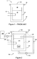
- FIG. 1 A prior art dual vessel reactor is shown in Figure 1 in which a reactor 5 is shown having an inner vessel 10 within an outer vessel 20.
- the reactor 5 has a reactor lid 60 sealed to the outer vessel 20 using a metal API ring 70.
- a nitrogen environment 25 is established in the reactor 5.
- a heater 30 heats a liquid in the inner vessel 10 into which a reaction container may be placed. Heating of the inner vessel 10 and the inner vessel liquid 15 results in elevated temperature of the outer vessel 20 (for example it will rise in temperature until it is at the operating temperature of the inner vessel) and the necessity of a metal seal, such as the metal API seal 70.
- Figure 2 is an illustrative schematic of one embodiment of a dual vessel chemical reactor 100 wherein during operation a non-condensable gas is used to isolate an inner vessel 120 from an outer vessel 110. This isolation resulting in the cooling of the outer vessel 110 will be explained in more detail below.
- the chemical reactor 100 has an inner vessel 120 for containing a liquid 115.
- the liquid 115 may be one of a reaction solvent for either dissolving a reactant or suspending a reactant, a solution for providing heat transfer to a reaction container 210 upon heating of the solution, or may be a reactant in liquid phase for reacting with a reactant in suspension or in a reaction container 210.
- the liquid may be water which forms steam upon heating or another liquid that forms vapour upon heating.
- the liquid 115 may be any organic or inorganic liquid, preferably with a boiling point above about 25 °C. For the purposes of this disclosure, the term steam will be used to encompass both water steam and liquid vapour.
- An outer vessel 110 encapsulates the inner vessel 120 and together with a reactor lid 140 form the pressure vessel for the chemical reactor 100.
- the outer vessel is typically made of a corrosion resistant alloy of a suitable thickness to withstand reaction pressures experienced during a chemical reaction to be carried out in the reactor 100.
- the outer vessel may be made from coated steel to resist corrosion and does not have to be made from costly stainless steel.
- the outer vessel 110 may be made Monel®, Inconel® or Hastelloy®. Some coatings for the outer vessel 110 may include plasma, thermal coatings or weld cladding.
- the reactor lid 140 may be an automatic lid or a manually operated lid sealed to the outer vessel 110 when in a closed position by a seal 150.
- the seal 150 may be for example, but not limited, to a rubber o-ring or the like.
- o-rings depends on the temperature and the chemicals to which they will be exposed. For steam and temperatures below 200 °C o-rings made from ethylene propylene diene M-class rubber (EPDM), silicone rubber, Kalrex®, polyacrylate, Viton®, flurosilicone or AflafTM are available. The options become even wider if the outer vessel 110 is kept below 100 °C throughout the reaction. If necessary, the outer vessel 110 may be cooled so it does not go above a predetermined temperature. This additional cooling may be done for example, but not limited to by air or water cooling.
- An inner vessel lid 125 covers the inner vessel 120 but does not hermetically seal the inner vessel 120 from the outer vessel 110.
- the lid 125 has one or more valves, for example but not limited to flapper valves or the like that allow the pressure in the inner vessel 120 and the pressure between the inner vessel 120 and the outer vessel 110 to equilibrate.
- Such a setup also prevents or minimizes any damage to the inner vessel 120 if the pressure in it is changed quickly (i.e. the steam is vented).
- the valves allow pressure between the inner vessel 120 and the outer vessel 110 to equilibrate throughout the reaction.
- a heat source 130 is used to heat the liquid 115 in the inner vessel 120.
- the heat source 130 may be any suitable heat source suitable for heating liquid in a reactor.
- a flanged over-the-side immersion heater may be used or a band heater may be used which heats the outside of the inner vessel 120.
- external heating of the liquid 115 may be carried out using for circulation heaters where the liquid 115 is pumped out of the reactor 100, heated externally (by electricity, gas, etc.), and then pumped back into the inner vessel 120.
- a vapour injector for injecting heated vapour may used as described in co-pending Canadian patent application 2,582,815 .
- steam from the liquid 115 in the inner vessel 120 condenses on the outer vessel 110 during a reaction cooling the outer vessel 110.
- An optional pump 170 may be used to re-circulate liquid that condenses on the walls of the outer vessel 110 using piping 160.
- the reactor 100 uses a non-condensable gas between the vessels 110 and 120 to limit the condensation of steam onto the inside wall of the outer vessel 110 and thereby limit the heating of the outer vessel 110 by the steam and negate the increase in the operating pressure of the reactor by the addition of the non-condensable gas.
- Non-condensable gases are gases that will not condense on the walls of the outer vessel 110 under the operating conditions (temperature and pressure) of the reactor 100. They may be supplied as compressed gas at room temperature and include for example both inert and non-inert gases and include oxygen, nitrogen, air, argon, methane, ethane, ethylene, hydrogen, helium, carbon monoxide, nitric oxide, nitrous oxide, and combinations thereof, etc.
- the non-condensable gas is substantially partitioned during operation into the space between the inner 120 and outer vessels 110 and the steam is partitioned into the inner vessel 120, thereby reducing or negating the effects of Dalton's Law.
- a comparative example will be used to illustrate these effects as well as the partitioning of the non-condensable gas from the steam and the operation of the reactor 100.
- the inner vessel 120 may be constructed of any suitable material such as corrosion resistant alloys and alloys having a corrosion resistant coating. Exotic alloys may be used in the construction of the inner vessel 120 as the inner vessel 120 is much thinner than the outer vessel 110 and is therefore less expensive to fabricate.
- a nonlimiting example of alloys that may be used in fabricating the inner vessel are stainless steel, Inconel®, Monel®, hastealloy, etc.
- FIG. 1 A schematic of a dual reactor that does not partition the non-condensable gas is shown in Figure 1 .
- the dual reactor 5 does not have a cover and is used to illustrate one of the problems that has been overcome with the dual vessel reactor and method of carrying out a reaction as described herein with references to Figures 2 and 3 .
- the reactor 5 has water in the inner reactor and the remainder of the space is filled by pressurized nitrogen.
- the nitrogen has been set at a pressure that will create a partial pressure of 150 psi (1034 kpa) when the water has been heated to a certain temperature (for example 180 °C).
- the steam creates a partial pressure of water of 150 psi (1034 kpa).
- the pressure in the vessel would then be 300 psi (2068 kpa). It can be seen from this example that it is not desirable to add nitrogen or other non-condensable gases, to the vessel as it increases the operating pressure of the vessel and thus the cost of the vessel as higher operating pressures require thicker metal in construction of the outer pressure vessel.
- non-condensable gas such as nitrogen
- a reactor such as that described herein, for example with reference to Figure 2
- non-condensable gas such as nitrogen
- the non-condensable gas may be added to the reactor 100 using any suitable method and the reactor design is not limited to the method or apparatus for inputting the non-condensable gas.
- the non-condensable gas may be introduced through a series of valves (which may or may not be computer controlled), with pressure gauges to monitor their pressure. Introducing the non-condensable gas by computer control is the preferable method when introducing the non-condensable gas during the reaction.
- the non-condensable gas is added, for example, so that it will generate a pressure of approximately 150 psi (1034 kpa) when the nitrogen has been substantially partitioned in the space between the inner vessel 120 and the outer vessel 110.
- the partitioning process is a dynamic process.
- the non-condensable gas in the space between the inner 120 and outer 110 vessels then acts as an insulator between the inner 120 and outer 110 vessels limiting heat transfer and maintains the outer vessel 110 cooler than the inner vessel 120 without steam continuously condensing on it as in Figure 1 .
- a situation is achieved where the pressure in the space between the inner 120 and outer 110 vessels is about 150 psi (1034 kpa) (mainly from non-condensable gas) and an equal pressure is observed inside the inner vessel 120 (mainly from steam).
- the outer vessel 110 may be cooled using an external cooling device.
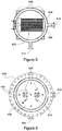
- Figure 4 depicts in a schematic an inner vessel 400 that may be used as the inner vessel 120 of a reactor as described above.
- Figures 5 and 6 depict in schematics cross sections of the inner vessel 400 taken along lines A-A' and B-B' respectively.
- the inner vessel 400 has an outer shell 402 and an inner shell 404.
- the inner shell 404 is covered by a cover 406.
- the inner shell 404 is not sealed by the cover 406, and liquid is able to freely pass between the inner shell 404 and the outer shell 402.
- the inner shell 404 provides a container where reactions may take place.
- the outer shell 404 is covered with a lid 408.
- the lid 408 has a collar 409 that seals the interior of the inner vessel 400; however, the lid 408 also includes passageways 412 that allow vapour, non-condensable gas, or a combination of the two to pass between the interior of the inner vessel 400 and the exterior of the inner vessel.
- the passageways 412 allow the interior of the inner vessel to be at a similar pressure as the interior of the outer vessel, which it is enclosed in.
- the inner vessel includes a plurality of ports 410, 414, 416.
- Ports 410 may be used to exhaust vapour or steam from the interior of the inner vessel 400 once the reaction is completed. This exhaust may be used, for example, to preheat other reactions occurring in other reactors. Exhausting the vapour through ports 410 helps to cool down the inner vessel 400 once the reaction is completed.
- Ports 414 may be used as inlet ports to fill the inner vessel with the required liquid and possibly any other reactants, required for the reactions.
- Port 416 may be used as an outlet for emptying the liquid from the interior of the inner vessel.
- the port 416 may also be used to circulate, and possibly heat, the liquid in the interior of the inner vessel 400. The liquid could, for example, be circulated from the port 416 and input back into the inner vessel 400 via one of the ports 414.
- a heater 418 comprising a plurality of heating elements 420 is suspended in the inner shell 404.
- the heater 418 is fixed to a flange 422 on the outer shell 402.
- the heater 418 may be fixed to the flange using, for example, bolts.
- the flange 422 allows an electrical wire 424 to pass through the outer shell 402, while maintaining the integrity of the outer shell 402.
- the inner vessel 400 may be seated on a bottom surface of the outer vessel, depicted as 428 in Figure 4 .
- the inner vessel may be raised off of the bottom surface 428 by a supporting structure, such as for example, support legs 426.
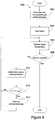
- Figure 7 depicts in a flow chart a method 700 of maintaining an outer vessel at a temperature below a reaction temperature.
- the method may be used to maintain the temperature of the outer vessel while carrying out a reaction in a dual vessel chemical reactor.
- the method begins with adding a non-condensable gas to the dual vessel reactor (702).
- the amount of non-condensable gas added may vary depending on the type of control used during the reaction. For example, a final amount of non-condensable gas may be added at the start, in which case further non-condensable case does not need to be added during the reaction. Alternatively a lower amount of non condensable gas may be added initially, and additional non condensable gas added during the reaction process.
- an initial amount of non-condensable gas is added to the dual vessel reactor.
- the liquid in the inner vessel is heated (704).
- the heating of the liquid brings the liquid temperature up to a reaction temperature.
- Vapour is formed from the heated liquid.
- the non-condensable gas and vapour is partitioned so that the vapour is substantially partitioned inside the inner vessel (704). This partitioning of the vapour to the interior of the inner vessel prevents vapour from condensing on the wall of the outer vessel, which would raise the temperature of the outer vessel.
- the vapour is partitioned as a result of the non-condensable gas.
- the partial pressure of the non-condensable gas is maintained above the partial pressure of the vapour, which in combination with the passageways between the inner and outer vessels restricts the vapour from escaping the interior of the inner vessel.
- Figure 8 depicts in a flow chart, a method 800 similar to method 700; however, the method 800 further comprises monitoring the temperature of the reaction to maintain a pressure differential between the non-condensable gas and the vapour.
- the method begins with adding an initial amount of non-condensable gas to the dual vessel reactor (802) and then heating the liquid (804) up to a reaction temperature.
- the method monitors the liquid temperature (806) and determines if the reaction is complete (808). If the reaction is complete (Yes at 808) the method ends. If the reaction is not complete (No at 808), the method determines a vapour partial pressure (P v ) that results from the liquid temperature (810).
- P v vapour partial pressure
- the method determines if the partial pressure of the non-condensable gas (P nc ) is less than or equal to P v plus a pressure differential ( ⁇ pres ) that is to be maintained (812). If it is less than or equal to (Yes at 812) then more non-condensable gas is added to the dual vessel reactor (814) to restore the desired pressure differential. The method then returns to monitor the temperature of the liquid (806). If P nc > P v + ⁇ pres (No at 812) the method returns to monitor the temperature of the liquid (806).
- the inner vessel may hold solid or large reactants, while further reactants may be added to the liquid that is heated.
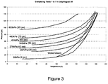
- a pressure vessel (outer vessel 110) was used that is 36 inches diameter and 10 ft long, and rated at 150 psi (1034 kpa). It has an inner vessel 120 that can hold approximately 800 L of liquid (in this case water). The water is heated with an immersion heater 130. Any open spaces between the inner 120 and outer 110 vessels were minimized and two flapper valves installed in the lid 140 to allow the pressure to equilibrate between the vessels 110 and 120.
- the experimental data has been supplemented with computer modeling.
- For the experimental set up i.e. volumes of the inner 120 and outer 110 vessels that contain non-condensable gas, etc) there is a cross over point. That is, at a starting pressure of about 70 psi (483 kpa) of non-condensable gas such as nitrogen, and at the end point, that is 180 °C, all the nitrogen that is in the inner vessel 120 has been purged out of the inner vessel 120 and the pressure of nitrogen in the space between the inner 120 and outer 110 vessels (which now contains the nitrogen that was originally in this space plus the nitrogen purged from the inner reactor) equals the pressure of the steam in the inner vessel 120. That is the steam and the nitrogen has been partitioned.
- non-condensable gas starting pressures below 70 psi (483 kpa) there is not sufficient non-condensable gas to fill the space between the two vessels 110 and 120 with non-condensable gas at 150 psi (1034 kpa) when the water is heated to 180 °C and there is what will be referred to as a "deficit" in non-condensable gas in the space between the vessels 110 and 120.
- This deficit is taken up by steam which can condense on the walls of the outer vessel 110 if the walls are cooler than the steam temperature.
- the bigger the deficit the larger the heat flow to the outer reactor will be as steam condenses on it.
- a useful starting pressure is about 70 psi (483 kpa). Under these conditions, and without any cooling to the outer vessel 110, the temperature rise of the vessel 110 was limited to 40°C versus 155°C if the non-condensable gas had not been there.
- some options for adding the non-condensable gas are but are not limited to:
- the non-condensable gas is added and the vapour pushes it out of the inner vessel 120 into the space between the inner vessel 120 and the outer vessel 110.
- the process of pushing the non-condensable gas out of the inner vessel 120 also results in the transfer of steam into the space between the vessel 110 and 120 followed by the condensation of the steam onto the outer vessel 110.
- this transfer is limited by adding the non-condensable gas as it is needed.
- a small pressure (for example 10 psi (68 kpa)) of the non-condensable gas is used at the start of the process in the reactor 100.
- non-condensable gas is added to the space between the vessels 110 and 120 to maintain a pressure that is above the pressure of the steam in the inner vessel 120.
- the excess pressure may be 10 psi (68 kpa).
- the 10 psi (68 kpa) is an example of what could be used for lower pressure reactions (for example up to 150 psi (1034 kpa)) but this pressure could be much higher for operations at higher pressures.
- the vapour pressure of the liquid 115 may be determined by measuring its temperature as it is being heated and computing its vapour pressure.
- the reactor 100 may operate at much higher pressures of 500 psi (3447 kpa) or 1000 psi (6894 kpa) as necessary for carrying out a specific reaction.
- the concept of partitioning the non-condensable gas from the steam for cooling the outer vessel 110 applies at high pressures as well and the examples above are merely illustrative and not limiting.
- the thickness of the pressure vessel increases as the pressure increases. Reaction pressures of up to 2,000 psi (13790 kpa) may be carried out in a reactor as described herein.
- the devulcanization of rubber may be carried out in a reactor as described herein at a reaction pressure of not over 2000 psi (13790 kpa) and a reaction temperature of not over 350 °C.
- the outer vessel 110 is kept cool by minimizing thermal contact between the two vessels 110 and 120 and by insulating the inner vessel 120 from the outer vessel 110 using the partitioned non-condensable gas and the vapour as described above. Some heat transfer through the non-condensable gas between the vessels 110 and 120 is observed, and of course any steam that condenses on the outer vessel 110 transfers heat.
- the condensation of steam can be reduced by introducing the non-condensable gas during the reaction and maintaining an excess pressure of the non-condensable gas over the steam as outlined in option 3 above.
- the non-condensable gas is introduced by computer control.
Landscapes
- Chemical & Material Sciences (AREA)
- Organic Chemistry (AREA)
- Chemical Kinetics & Catalysis (AREA)
- Life Sciences & Earth Sciences (AREA)
- Sustainable Development (AREA)
- Health & Medical Sciences (AREA)
- Medicinal Chemistry (AREA)
- Polymers & Plastics (AREA)
- Physical Or Chemical Processes And Apparatus (AREA)
Claims (14)
- Réacteur chimique à double cuve (100) comprenant :une cuve extérieure (110) destinée à soutenir une pression de réaction d'au moins 34,5 bar (500 psi) et jusqu'à 137,9 bar (2 000 psi) ;une entrée de gaz non condensable (200) destinée à entrer un gaz non condensable jusque dans la cuve extérieure (110) pour isoler sensiblement la cuve extérieure (110) d'une cuve intérieure (120) en cours de fonctionnement ;un couvercle de réacteur (140) sur la cuve extérieure (110), le couvercle de réacteur (140) pouvant être ouvert pour accéder à la cuve intérieure (120) ;la cuve intérieure (120) à l'intérieur de la cuve extérieure (110) destinée à contenir un liquide (115), la cuve intérieure (120) étant en communication atmosphérique avec la cuve extérieure (110) ;une source de chaleur (130) pour chauffer le liquide (115) dans la cuve intérieure (120) ;un joint (150) pour étancher le couvercle de réacteur (140) avec la cuve extérieure (110) dans une position fermée ;un couvercle de cuve intérieure (125) destiné à couvrir la cuve intérieure (120),caractérisé parune valve dans le couvercle de cuve intérieure (125) pour permettre un équilibrage de la pression dans la cuve intérieure (120) et entre la cuve intérieure (120) et la cuve extérieure (110).
- Réacteur (100) selon la revendication 1,
dans lequel le réacteur (100) comprend en outre :un réservoir de gaz non condensable (180) en communication avec l'entrée de gaz non condensable (200) ; etune valve (190) destinée à ouvrir et à fermer l'entrée de gaz non condensable (200) jusque dans la cuve extérieure (110). - Réacteur (100) selon la revendication 1 ou 2, dans lequel le joint (150) est un élément parmi : un joint en métal, un joint torique en caoutchouc, ou une garniture composite, de préférence un joint torique en caoutchouc, et de manière plus préférée un joint torique en caoutchouc comprenant un caoutchouc parmi un caoutchouc éthylène propylène diène de classe M (EPDM), un caoutchouc silicone, Kalrex®, polyacrylate, Viton®, fluorosilicone ou Aflaf™.
- Réacteur (100) selon l'une quelconque des revendications 1 à 3, dans lequel la cuve extérieure (110) est réalisée à partir d'un alliage résistant à la corrosion, en particulier d'un alliage résistant à la corrosion qui est un acier inoxydable, Inconel® ou Monel®, et/ou est réalisée à partir d'un alliage enrobé avec un enrobage sélectionné parmi le groupe constitué de : peinture, émail, plasma, revêtement thermique, galvanisé, par placage et par soudage.
- Procédé pour maintenir une cuve extérieure (110) à une température en dessous d'une température de réaction tout en supportant une réaction dans un réacteur chimique à double cuve (100) selon la revendication 1, le procédé comprenant les étapes consistant à :ajouter un gaz non condensable au réacteur (100) ;chauffer un liquide (115) dans la cuve intérieure (120) pour générer une vapeur ; etcloisonner sensiblement le gaz non condensable dans la cuve extérieure (110) et la vapeur dans la cuve intérieure (120).
- Procédé selon la revendication 5, dans lequel le gaz non condensable est maintenu à une pression excessive relativement à la pression de vapeur du liquide (115) dans la cuve intérieure (120) quand le liquide (115) est chauffé.
- Procédé selon la revendication 6, dans lequel le gaz non condensable est ajouté dans l'espace entre la cuve intérieure (120) et la cuve extérieure (110) pendant la réaction pour maintenir la pression excessive relativement à la pression de vapeur du liquide (115), cloisonnant ainsi le gaz non condensable dans la cuve extérieure (110) et la vapeur dans la cuve intérieure (120).
- Procédé selon l'une quelconque des revendications 5 à 7, dans lequel l'étape consistant à cloisonner sensiblement le gaz non condensable est achevée par condensation de la vapeur dans l'espace entre la cuve extérieure (110) et la cuve intérieure (120) sur la cuve extérieure (110).
- Procédé selon l'une quelconque des revendications 5 à 8, dans lequel le gaz non condensable est ajouté au réacteur (100) avant de chauffer le liquide (115) dans la cuve intérieure (120).
- Procédé selon l'une quelconque des revendications 5 à 9, dans lequel le gaz non condensable est ajouté à une pression prédéterminée de sorte que, après l'étape consistant à cloisonner sensiblement le gaz non condensable, le gaz non condensable est à une pression de réaction.
- Procédé selon l'une quelconque des revendications 5 à 10, dans lequel le gaz non condensable est un élément ou une combinaison d'éléments parmi : oxygène, azote, air, argon, méthane, éthane, éthylène, hydrogène, hélium, monoxyde de carbone, oxyde nitrique ou oxyde nitreux, et est de préférence de l'azote.
- Procédé selon l'une quelconque des revendications 5 à 11, comprenant en outre l'étape consistant à ajouter un réactif d'une réaction chimique au liquide (115) dans la cuve intérieure (120) avant de chauffer le liquide (115) dans la cuve intérieure (120).
- Procédé selon la revendication 12, dans lequel la réaction chimique est la dévulcanisation de caoutchouc.
- Procédé selon la revendication 5, dans lequel la cuve extérieure (110) est maintenue à ou en dessous de 225 °C pendant le fonctionnement du réacteur (100).
Applications Claiming Priority (2)
| Application Number | Priority Date | Filing Date | Title |
|---|---|---|---|
| US10001408P | 2008-09-25 | 2008-09-25 | |
| PCT/CA2009/001361 WO2010034123A1 (fr) | 2008-09-25 | 2009-09-25 | Réacteur à double cuve |
Publications (3)
| Publication Number | Publication Date |
|---|---|
| EP2349554A1 EP2349554A1 (fr) | 2011-08-03 |
| EP2349554A4 EP2349554A4 (fr) | 2016-09-21 |
| EP2349554B1 true EP2349554B1 (fr) | 2021-03-17 |
Family
ID=42059247
Family Applications (1)
| Application Number | Title | Priority Date | Filing Date |
|---|---|---|---|
| EP09815535.1A Active EP2349554B1 (fr) | 2008-09-25 | 2009-09-25 | Réacteur à double cuve |
Country Status (10)
| Country | Link |
|---|---|
| US (2) | US9403136B2 (fr) |
| EP (1) | EP2349554B1 (fr) |
| JP (1) | JP5820723B2 (fr) |
| CN (1) | CN102223948B (fr) |
| AU (1) | AU2009295321B2 (fr) |
| BR (1) | BRPI0920869A2 (fr) |
| CA (1) | CA2738344C (fr) |
| ES (1) | ES2872102T3 (fr) |
| MX (1) | MX2011003068A (fr) |
| WO (1) | WO2010034123A1 (fr) |
Families Citing this family (3)
| Publication number | Priority date | Publication date | Assignee | Title |
|---|---|---|---|---|
| CA2892836C (fr) * | 2012-11-27 | 2019-01-08 | Brian H. Harrison | Conversion de caoutchouc vulcanise |
| CN112705149B (zh) * | 2019-10-25 | 2022-10-21 | 中国石油化工股份有限公司 | 一种内衬石英反应器 |
| TWI739535B (zh) * | 2020-07-31 | 2021-09-11 | 鐘介宏 | 高壓水解設備及其方法 |
Family Cites Families (19)
| Publication number | Priority date | Publication date | Assignee | Title |
|---|---|---|---|---|
| US3056664A (en) | 1959-03-12 | 1962-10-02 | Standard Oil Co | Apparatus for handling corrosive materials at high pressures and temperatures |
| FR1595711A (fr) * | 1968-11-21 | 1970-06-15 | ||
| US3659584A (en) | 1970-02-11 | 1972-05-02 | Continental Can Co | Stove top heating containers |
| US4167968A (en) | 1977-12-30 | 1979-09-18 | Babcock-Brown Boveri Reaktor Gmbh | Pressure vessel |
| US4892707A (en) | 1983-07-25 | 1990-01-09 | American Cyanamid Company | Apparatus for the calorimetry of chemical processes |
| US4963499A (en) | 1983-07-25 | 1990-10-16 | American Cyanamid Company | Method for the calorimetry of chemical processes |
| US4827180A (en) | 1986-11-20 | 1989-05-02 | Kabushiki Kaisha Toshiba | Color picture tube with support members for the mask frame |
| EP0462383B1 (fr) * | 1990-06-21 | 1994-10-26 | Pfaudler, Inc. | Fermeture pour un réacteur chimique propre |
| TW259720B (en) * | 1994-06-29 | 1995-10-11 | Kimberly Clark Co | Reactor for high temperature, elevated pressure, corrosive reactions |
| US5557162A (en) | 1995-01-18 | 1996-09-17 | Samsung Display Devices Co., Ltd. | Color picture tube with a shadow mask support member |
| CN1070450C (zh) * | 1995-03-29 | 2001-09-05 | 日本酸素株式会社 | 绝热容器与绝热材料及绝热容器的制造方法 |
| US5762341A (en) | 1997-01-13 | 1998-06-09 | Zygo Mould Limited | O-ring insert |
| US6939521B1 (en) * | 1997-11-21 | 2005-09-06 | Honeywell International Inc. | Fluoropolymer reactor with heat exchange jacket |
| JP4327410B2 (ja) * | 2002-05-29 | 2009-09-09 | オルガノ株式会社 | バッチ式水熱反応器及び水熱反応装置 |
| JP2005334848A (ja) * | 2004-05-31 | 2005-12-08 | Japan Organo Co Ltd | 圧力バランス型反応装置およびその運転方法 |
| SE0502436L (sv) * | 2005-11-02 | 2007-05-03 | Stena Miljoeteknik Ab | Satsvis depolymerisation av kolvätematerial |
| CA2541035A1 (fr) | 2006-03-27 | 2007-09-27 | Brian H. Harrison | Reacteur pour reduction chimique du caoutchouc |
| CA2582815A1 (fr) | 2006-03-27 | 2007-09-27 | Rubreco Inc. | Reacteur et systeme a reacteur |
| US20080044342A1 (en) * | 2006-08-15 | 2008-02-21 | Muller John J | Fail-safe, on-demand sulfurous acid generator |
-
2009
- 2009-09-25 JP JP2011528151A patent/JP5820723B2/ja active Active
- 2009-09-25 BR BRPI0920869-0A patent/BRPI0920869A2/pt not_active Application Discontinuation
- 2009-09-25 MX MX2011003068A patent/MX2011003068A/es not_active Application Discontinuation
- 2009-09-25 WO PCT/CA2009/001361 patent/WO2010034123A1/fr active Application Filing
- 2009-09-25 AU AU2009295321A patent/AU2009295321B2/en not_active Ceased
- 2009-09-25 EP EP09815535.1A patent/EP2349554B1/fr active Active
- 2009-09-25 US US12/567,133 patent/US9403136B2/en active Active
- 2009-09-25 CA CA2738344A patent/CA2738344C/fr active Active
- 2009-09-25 CN CN200980147175.2A patent/CN102223948B/zh active Active
- 2009-09-25 ES ES09815535T patent/ES2872102T3/es active Active
-
2016
- 2016-07-08 US US15/205,353 patent/US9901890B2/en active Active
Non-Patent Citations (1)
| Title |
|---|
| None * |
Also Published As
| Publication number | Publication date |
|---|---|
| JP5820723B2 (ja) | 2015-11-24 |
| CN102223948A (zh) | 2011-10-19 |
| JP2012503535A (ja) | 2012-02-09 |
| CN102223948B (zh) | 2016-10-19 |
| EP2349554A1 (fr) | 2011-08-03 |
| ES2872102T3 (es) | 2021-11-02 |
| US20100113705A1 (en) | 2010-05-06 |
| US9403136B2 (en) | 2016-08-02 |
| CA2738344C (fr) | 2017-01-24 |
| WO2010034123A1 (fr) | 2010-04-01 |
| CA2738344A1 (fr) | 2010-04-01 |
| AU2009295321A1 (en) | 2010-04-01 |
| US9901890B2 (en) | 2018-02-27 |
| EP2349554A4 (fr) | 2016-09-21 |
| MX2011003068A (es) | 2011-09-26 |
| AU2009295321B2 (en) | 2014-08-07 |
| BRPI0920869A2 (pt) | 2020-12-08 |
| US20160325251A1 (en) | 2016-11-10 |
Similar Documents
| Publication | Publication Date | Title |
|---|---|---|
| TWI678737B (zh) | 高壓蒸氣退火處理設備 | |
| US9901890B2 (en) | Dual vessel reactor | |
| JP5225862B2 (ja) | 高圧ガスアニーリング装置及び方法 | |
| US8790585B2 (en) | Countercurrent tank type supercritical water reactor with a sacrificial lining | |
| CN101443105B (zh) | 用于高温高压反应的反应堆和反应堆系统 | |
| WO2009098452A2 (fr) | Conversion d'ammoniac en azote et en hydrogène | |
| US9649612B2 (en) | Dual vessel reactor | |
| KR102356206B1 (ko) | 내부 열 교환을 갖는 부식 방지 개질기 튜브 | |
| KR20130135235A (ko) | 하소 챔버 및 그 방법 | |
| JP2681132B2 (ja) | 危険廃棄物用改良オートクレーブ | |
| RU2352685C2 (ru) | Простая система химического осаждения из паров и способы нанесения многометаллических алюминидных покрытий | |
| US20220205734A1 (en) | High-temperature fluid transporting pipeline with pipeline casing formed by heat exchange apparatus, suitable heat exchange apparatus and heat exchange method | |
| US2884894A (en) | Apparatus for producing hard coatings on workpieces | |
| US11940228B2 (en) | High-temperature fluid transporting pipeline with heat exchange apparatus installed therein, suitable heat exchange apparatus and heat exchange method | |
| US20160230279A1 (en) | Isothermal warm wall cvd reactor | |
| RU2693800C1 (ru) | Устройство для переработки отходов из резинотехнических и полимерных материалов | |
| Childers et al. | Chemical Vapor Deposition Methane Pyrolysis Enables Closed-Loop Oxygen Recovery: Path to Flight | |
| JP2004332039A (ja) | Cvd用反応容器 | |
| JP4446665B2 (ja) | 反応温度の制御方法及びそれに使用する装置 | |
| WO2008043313A1 (fr) | Système de réaction | |
| KR102124862B1 (ko) | 광케이블 및 폐합성수지용 열분해처리장치 | |
| JPS63267883A (ja) | 熱間静水圧プレス装置 |
Legal Events
| Date | Code | Title | Description |
|---|---|---|---|
| PUAI | Public reference made under article 153(3) epc to a published international application that has entered the european phase |
Free format text: ORIGINAL CODE: 0009012 |
|
| 17P | Request for examination filed |
Effective date: 20110421 |
|
| AK | Designated contracting states |
Kind code of ref document: A1 Designated state(s): AT BE BG CH CY CZ DE DK EE ES FI FR GB GR HR HU IE IS IT LI LT LU LV MC MK MT NL NO PL PT RO SE SI SK SM TR |
|
| DAX | Request for extension of the european patent (deleted) | ||
| RAP1 | Party data changed (applicant data changed or rights of an application transferred) |
Owner name: RUBRECO INC. |
|
| RIN1 | Information on inventor provided before grant (corrected) |
Inventor name: HOOPER, HURDON A. Inventor name: HARRISON, BRIAN |
|
| RA4 | Supplementary search report drawn up and despatched (corrected) |
Effective date: 20160819 |
|
| RIC1 | Information provided on ipc code assigned before grant |
Ipc: B01J 3/04 20060101AFI20160812BHEP Ipc: B01J 3/03 20060101ALI20160812BHEP Ipc: B01J 19/02 20060101ALI20160812BHEP |
|
| STAA | Information on the status of an ep patent application or granted ep patent |
Free format text: STATUS: EXAMINATION IS IN PROGRESS |
|
| 17Q | First examination report despatched |
Effective date: 20180312 |
|
| REG | Reference to a national code |
Ref country code: DE Ref legal event code: R079 Ref document number: 602009063471 Country of ref document: DE Free format text: PREVIOUS MAIN CLASS: B01J0019240000 Ipc: B01J0003040000 |
|
| RIC1 | Information provided on ipc code assigned before grant |
Ipc: B01J 3/03 20060101ALI20200520BHEP Ipc: B01J 3/04 20060101AFI20200520BHEP |
|
| GRAP | Despatch of communication of intention to grant a patent |
Free format text: ORIGINAL CODE: EPIDOSNIGR1 |
|
| STAA | Information on the status of an ep patent application or granted ep patent |
Free format text: STATUS: GRANT OF PATENT IS INTENDED |
|
| INTG | Intention to grant announced |
Effective date: 20200804 |
|
| GRAS | Grant fee paid |
Free format text: ORIGINAL CODE: EPIDOSNIGR3 |
|
| GRAA | (expected) grant |
Free format text: ORIGINAL CODE: 0009210 |
|
| STAA | Information on the status of an ep patent application or granted ep patent |
Free format text: STATUS: THE PATENT HAS BEEN GRANTED |
|
| AK | Designated contracting states |
Kind code of ref document: B1 Designated state(s): AT BE BG CH CY CZ DE DK EE ES FI FR GB GR HR HU IE IS IT LI LT LU LV MC MK MT NL NO PL PT RO SE SI SK SM TR |
|
| REG | Reference to a national code |
Ref country code: GB Ref legal event code: FG4D |
|
| REG | Reference to a national code |
Ref country code: CH Ref legal event code: EP |
|
| REG | Reference to a national code |
Ref country code: DE Ref legal event code: R096 Ref document number: 602009063471 Country of ref document: DE |
|
| REG | Reference to a national code |
Ref country code: IE Ref legal event code: FG4D |
|
| REG | Reference to a national code |
Ref country code: AT Ref legal event code: REF Ref document number: 1371731 Country of ref document: AT Kind code of ref document: T Effective date: 20210415 |
|
| REG | Reference to a national code |
Ref country code: LT Ref legal event code: MG9D |
|
| PG25 | Lapsed in a contracting state [announced via postgrant information from national office to epo] |
Ref country code: NO Free format text: LAPSE BECAUSE OF FAILURE TO SUBMIT A TRANSLATION OF THE DESCRIPTION OR TO PAY THE FEE WITHIN THE PRESCRIBED TIME-LIMIT Effective date: 20210617 Ref country code: BG Free format text: LAPSE BECAUSE OF FAILURE TO SUBMIT A TRANSLATION OF THE DESCRIPTION OR TO PAY THE FEE WITHIN THE PRESCRIBED TIME-LIMIT Effective date: 20210617 Ref country code: GR Free format text: LAPSE BECAUSE OF FAILURE TO SUBMIT A TRANSLATION OF THE DESCRIPTION OR TO PAY THE FEE WITHIN THE PRESCRIBED TIME-LIMIT Effective date: 20210618 Ref country code: FI Free format text: LAPSE BECAUSE OF FAILURE TO SUBMIT A TRANSLATION OF THE DESCRIPTION OR TO PAY THE FEE WITHIN THE PRESCRIBED TIME-LIMIT Effective date: 20210317 Ref country code: HR Free format text: LAPSE BECAUSE OF FAILURE TO SUBMIT A TRANSLATION OF THE DESCRIPTION OR TO PAY THE FEE WITHIN THE PRESCRIBED TIME-LIMIT Effective date: 20210317 |
|
| REG | Reference to a national code |
Ref country code: AT Ref legal event code: MK05 Ref document number: 1371731 Country of ref document: AT Kind code of ref document: T Effective date: 20210317 |
|
| REG | Reference to a national code |
Ref country code: NL Ref legal event code: MP Effective date: 20210317 |
|
| PG25 | Lapsed in a contracting state [announced via postgrant information from national office to epo] |
Ref country code: LV Free format text: LAPSE BECAUSE OF FAILURE TO SUBMIT A TRANSLATION OF THE DESCRIPTION OR TO PAY THE FEE WITHIN THE PRESCRIBED TIME-LIMIT Effective date: 20210317 Ref country code: SE Free format text: LAPSE BECAUSE OF FAILURE TO SUBMIT A TRANSLATION OF THE DESCRIPTION OR TO PAY THE FEE WITHIN THE PRESCRIBED TIME-LIMIT Effective date: 20210317 |
|
| PG25 | Lapsed in a contracting state [announced via postgrant information from national office to epo] |
Ref country code: NL Free format text: LAPSE BECAUSE OF FAILURE TO SUBMIT A TRANSLATION OF THE DESCRIPTION OR TO PAY THE FEE WITHIN THE PRESCRIBED TIME-LIMIT Effective date: 20210317 |
|
| PG25 | Lapsed in a contracting state [announced via postgrant information from national office to epo] |
Ref country code: EE Free format text: LAPSE BECAUSE OF FAILURE TO SUBMIT A TRANSLATION OF THE DESCRIPTION OR TO PAY THE FEE WITHIN THE PRESCRIBED TIME-LIMIT Effective date: 20210317 Ref country code: CZ Free format text: LAPSE BECAUSE OF FAILURE TO SUBMIT A TRANSLATION OF THE DESCRIPTION OR TO PAY THE FEE WITHIN THE PRESCRIBED TIME-LIMIT Effective date: 20210317 Ref country code: LT Free format text: LAPSE BECAUSE OF FAILURE TO SUBMIT A TRANSLATION OF THE DESCRIPTION OR TO PAY THE FEE WITHIN THE PRESCRIBED TIME-LIMIT Effective date: 20210317 Ref country code: AT Free format text: LAPSE BECAUSE OF FAILURE TO SUBMIT A TRANSLATION OF THE DESCRIPTION OR TO PAY THE FEE WITHIN THE PRESCRIBED TIME-LIMIT Effective date: 20210317 Ref country code: SM Free format text: LAPSE BECAUSE OF FAILURE TO SUBMIT A TRANSLATION OF THE DESCRIPTION OR TO PAY THE FEE WITHIN THE PRESCRIBED TIME-LIMIT Effective date: 20210317 |
|
| REG | Reference to a national code |
Ref country code: ES Ref legal event code: FG2A Ref document number: 2872102 Country of ref document: ES Kind code of ref document: T3 Effective date: 20211102 |
|
| PG25 | Lapsed in a contracting state [announced via postgrant information from national office to epo] |
Ref country code: PT Free format text: LAPSE BECAUSE OF FAILURE TO SUBMIT A TRANSLATION OF THE DESCRIPTION OR TO PAY THE FEE WITHIN THE PRESCRIBED TIME-LIMIT Effective date: 20210719 Ref country code: PL Free format text: LAPSE BECAUSE OF FAILURE TO SUBMIT A TRANSLATION OF THE DESCRIPTION OR TO PAY THE FEE WITHIN THE PRESCRIBED TIME-LIMIT Effective date: 20210317 Ref country code: SK Free format text: LAPSE BECAUSE OF FAILURE TO SUBMIT A TRANSLATION OF THE DESCRIPTION OR TO PAY THE FEE WITHIN THE PRESCRIBED TIME-LIMIT Effective date: 20210317 Ref country code: IS Free format text: LAPSE BECAUSE OF FAILURE TO SUBMIT A TRANSLATION OF THE DESCRIPTION OR TO PAY THE FEE WITHIN THE PRESCRIBED TIME-LIMIT Effective date: 20210717 Ref country code: RO Free format text: LAPSE BECAUSE OF FAILURE TO SUBMIT A TRANSLATION OF THE DESCRIPTION OR TO PAY THE FEE WITHIN THE PRESCRIBED TIME-LIMIT Effective date: 20210317 |
|
| REG | Reference to a national code |
Ref country code: DE Ref legal event code: R097 Ref document number: 602009063471 Country of ref document: DE |
|
| PLBE | No opposition filed within time limit |
Free format text: ORIGINAL CODE: 0009261 |
|
| STAA | Information on the status of an ep patent application or granted ep patent |
Free format text: STATUS: NO OPPOSITION FILED WITHIN TIME LIMIT |
|
| PG25 | Lapsed in a contracting state [announced via postgrant information from national office to epo] |
Ref country code: DK Free format text: LAPSE BECAUSE OF FAILURE TO SUBMIT A TRANSLATION OF THE DESCRIPTION OR TO PAY THE FEE WITHIN THE PRESCRIBED TIME-LIMIT Effective date: 20210317 |
|
| 26N | No opposition filed |
Effective date: 20211220 |
|
| PG25 | Lapsed in a contracting state [announced via postgrant information from national office to epo] |
Ref country code: SI Free format text: LAPSE BECAUSE OF FAILURE TO SUBMIT A TRANSLATION OF THE DESCRIPTION OR TO PAY THE FEE WITHIN THE PRESCRIBED TIME-LIMIT Effective date: 20210317 |
|
| REG | Reference to a national code |
Ref country code: CH Ref legal event code: PL |
|
| REG | Reference to a national code |
Ref country code: BE Ref legal event code: MM Effective date: 20210930 |
|
| PG25 | Lapsed in a contracting state [announced via postgrant information from national office to epo] |
Ref country code: IS Free format text: LAPSE BECAUSE OF FAILURE TO SUBMIT A TRANSLATION OF THE DESCRIPTION OR TO PAY THE FEE WITHIN THE PRESCRIBED TIME-LIMIT Effective date: 20210717 Ref country code: MC Free format text: LAPSE BECAUSE OF FAILURE TO SUBMIT A TRANSLATION OF THE DESCRIPTION OR TO PAY THE FEE WITHIN THE PRESCRIBED TIME-LIMIT Effective date: 20210317 |
|
| PG25 | Lapsed in a contracting state [announced via postgrant information from national office to epo] |
Ref country code: LU Free format text: LAPSE BECAUSE OF NON-PAYMENT OF DUE FEES Effective date: 20210925 Ref country code: IE Free format text: LAPSE BECAUSE OF NON-PAYMENT OF DUE FEES Effective date: 20210925 Ref country code: BE Free format text: LAPSE BECAUSE OF NON-PAYMENT OF DUE FEES Effective date: 20210930 |
|
| PG25 | Lapsed in a contracting state [announced via postgrant information from national office to epo] |
Ref country code: LI Free format text: LAPSE BECAUSE OF NON-PAYMENT OF DUE FEES Effective date: 20210930 Ref country code: CH Free format text: LAPSE BECAUSE OF NON-PAYMENT OF DUE FEES Effective date: 20210930 |
|
| PGFP | Annual fee paid to national office [announced via postgrant information from national office to epo] |
Ref country code: GB Payment date: 20220915 Year of fee payment: 14 Ref country code: DE Payment date: 20220921 Year of fee payment: 14 |
|
| PGFP | Annual fee paid to national office [announced via postgrant information from national office to epo] |
Ref country code: FR Payment date: 20220921 Year of fee payment: 14 |
|
| PGFP | Annual fee paid to national office [announced via postgrant information from national office to epo] |
Ref country code: IT Payment date: 20220927 Year of fee payment: 14 Ref country code: ES Payment date: 20221005 Year of fee payment: 14 |
|
| PG25 | Lapsed in a contracting state [announced via postgrant information from national office to epo] |
Ref country code: HU Free format text: LAPSE BECAUSE OF FAILURE TO SUBMIT A TRANSLATION OF THE DESCRIPTION OR TO PAY THE FEE WITHIN THE PRESCRIBED TIME-LIMIT; INVALID AB INITIO Effective date: 20090925 Ref country code: CY Free format text: LAPSE BECAUSE OF FAILURE TO SUBMIT A TRANSLATION OF THE DESCRIPTION OR TO PAY THE FEE WITHIN THE PRESCRIBED TIME-LIMIT Effective date: 20210317 |
|
| PG25 | Lapsed in a contracting state [announced via postgrant information from national office to epo] |
Ref country code: MK Free format text: LAPSE BECAUSE OF FAILURE TO SUBMIT A TRANSLATION OF THE DESCRIPTION OR TO PAY THE FEE WITHIN THE PRESCRIBED TIME-LIMIT Effective date: 20210317 |