US5762341A - O-ring insert - Google Patents
O-ring insert Download PDFInfo
- Publication number
- US5762341A US5762341A US08/782,914 US78291497A US5762341A US 5762341 A US5762341 A US 5762341A US 78291497 A US78291497 A US 78291497A US 5762341 A US5762341 A US 5762341A
- Authority
- US
- United States
- Prior art keywords
- recess
- diameter
- bore
- stem portion
- face
- Prior art date
- Legal status (The legal status is an assumption and is not a legal conclusion. Google has not performed a legal analysis and makes no representation as to the accuracy of the status listed.)
- Expired - Fee Related
Links
- 238000000034 method Methods 0.000 claims abstract description 37
- 239000000463 material Substances 0.000 claims abstract description 15
- 230000000717 retained effect Effects 0.000 claims abstract description 10
- 230000013011 mating Effects 0.000 claims description 53
- 239000012530 fluid Substances 0.000 claims description 23
- 239000011343 solid material Substances 0.000 claims description 15
- 238000005553 drilling Methods 0.000 claims description 10
- 238000001746 injection moulding Methods 0.000 claims description 7
- 230000009471 action Effects 0.000 claims description 4
- 238000007789 sealing Methods 0.000 claims description 2
- 238000006073 displacement reaction Methods 0.000 description 6
- 238000004519 manufacturing process Methods 0.000 description 3
- 229910052751 metal Inorganic materials 0.000 description 3
- 239000002184 metal Substances 0.000 description 3
- 238000000465 moulding Methods 0.000 description 3
- 239000004033 plastic Substances 0.000 description 3
- 229920003023 plastic Polymers 0.000 description 3
- -1 polypropylene Polymers 0.000 description 3
- 239000000853 adhesive Substances 0.000 description 2
- 230000001070 adhesive effect Effects 0.000 description 2
- 238000006243 chemical reaction Methods 0.000 description 2
- 230000006866 deterioration Effects 0.000 description 2
- 230000000694 effects Effects 0.000 description 2
- 238000009434 installation Methods 0.000 description 2
- 239000007788 liquid Substances 0.000 description 2
- 238000003801 milling Methods 0.000 description 2
- 229920002292 Nylon 6 Polymers 0.000 description 1
- 239000004698 Polyethylene Substances 0.000 description 1
- 239000004743 Polypropylene Substances 0.000 description 1
- 229910000831 Steel Inorganic materials 0.000 description 1
- 229920006362 Teflon® Polymers 0.000 description 1
- 238000005299 abrasion Methods 0.000 description 1
- 229920000122 acrylonitrile butadiene styrene Polymers 0.000 description 1
- 230000002411 adverse Effects 0.000 description 1
- 229910052782 aluminium Inorganic materials 0.000 description 1
- XAGFODPZIPBFFR-UHFFFAOYSA-N aluminium Chemical compound [Al] XAGFODPZIPBFFR-UHFFFAOYSA-N 0.000 description 1
- 230000005540 biological transmission Effects 0.000 description 1
- 230000008859 change Effects 0.000 description 1
- 239000012809 cooling fluid Substances 0.000 description 1
- 238000005260 corrosion Methods 0.000 description 1
- 230000007797 corrosion Effects 0.000 description 1
- 239000007789 gas Substances 0.000 description 1
- 239000011521 glass Substances 0.000 description 1
- 238000010438 heat treatment Methods 0.000 description 1
- 238000003780 insertion Methods 0.000 description 1
- 230000037431 insertion Effects 0.000 description 1
- 239000000314 lubricant Substances 0.000 description 1
- 239000000155 melt Substances 0.000 description 1
- 239000007769 metal material Substances 0.000 description 1
- 238000012986 modification Methods 0.000 description 1
- 230000004048 modification Effects 0.000 description 1
- 229920001084 poly(chloroprene) Polymers 0.000 description 1
- 229920000573 polyethylene Polymers 0.000 description 1
- 229920001155 polypropylene Polymers 0.000 description 1
- 229920001343 polytetrafluoroethylene Polymers 0.000 description 1
- 239000004810 polytetrafluoroethylene Substances 0.000 description 1
- 229920000915 polyvinyl chloride Polymers 0.000 description 1
- 239000002243 precursor Substances 0.000 description 1
- 230000008569 process Effects 0.000 description 1
- 239000000565 sealant Substances 0.000 description 1
- 238000007493 shaping process Methods 0.000 description 1
- 229920002379 silicone rubber Polymers 0.000 description 1
- 239000004945 silicone rubber Substances 0.000 description 1
- 239000000243 solution Substances 0.000 description 1
- 229910001220 stainless steel Inorganic materials 0.000 description 1
- 239000010935 stainless steel Substances 0.000 description 1
- 239000010959 steel Substances 0.000 description 1
- 229920002994 synthetic fiber Polymers 0.000 description 1
- 231100000331 toxic Toxicity 0.000 description 1
- 230000002588 toxic effect Effects 0.000 description 1
- XLYOFNOQVPJJNP-UHFFFAOYSA-N water Substances O XLYOFNOQVPJJNP-UHFFFAOYSA-N 0.000 description 1
Images


Classifications
-
- F—MECHANICAL ENGINEERING; LIGHTING; HEATING; WEAPONS; BLASTING
- F16—ENGINEERING ELEMENTS AND UNITS; GENERAL MEASURES FOR PRODUCING AND MAINTAINING EFFECTIVE FUNCTIONING OF MACHINES OR INSTALLATIONS; THERMAL INSULATION IN GENERAL
- F16J—PISTONS; CYLINDERS; SEALINGS
- F16J15/00—Sealings
- F16J15/02—Sealings between relatively-stationary surfaces
- F16J15/06—Sealings between relatively-stationary surfaces with solid packing compressed between sealing surfaces
- F16J15/062—Sealings between relatively-stationary surfaces with solid packing compressed between sealing surfaces characterised by the geometry of the seat
Definitions
- This invention relates to sealing methods and devices. More specifically, the invention relates to a device and method of providing a seal at the junction of axially aligned bores extending across the interface between two segments of solid material.
- one or more fluids typically under pressure, have to be delivered through bores extending through a plurality of blocks or segments.
- fluids include air and other gases; water, organic liquids and other aqueous and non-aqueous liquid mediums; melts; molten plastics and plastic material precursors; lubricants; etc.
- resilient rings having a substantially circular cross-section are most often used in applications where such blocks or segments have to be taken apart and assembled back together on a regular basis.
- An O-ring is typically inserted into an annular groove provided in the mating face of one of the blocks or segments, the groove being co-axial with the bore opening.
- the other mating face is generally flat.
- the depth of the annular groove is smaller than the depth of the O-ring so that the mating faces, when brought together, deform the ring and provide for a tight seal.
- the pressurized fluid additionally deforms the ring and provides for an even better seal.
- the shapes of the annular groove and opposing mating face should be such as to limit the displacement of the O-ring subjected to deformation forces.
- the dimensions of the groove therefore, are critical and any manufacturing imprecision, as well as any degree of corrosion or deterioration of the surfaces during operation of the device could lead to expulsion of the O-ring from its groove and loss of a proper seal.
- U.S. Pat, No. 3,698,7208 discloses a back-up ring designed to limit the displacement and reduce the abrasion of a resilient O-ring in the case of unevenly manufactured or corroded surfaces.
- Gastineau et al. in U.S. Pat. No. 3,262,722, employ a similar approach to hollow metallic O-rings.
- U.S. Pat. 4,034,993 to Okada et al. discloses two back-up rings placed inside the groove together with a resilient O-ring to direct its displacement and to ensure a proper seal even in the case the mating faces have not been brought completely together. There are a number of limitations to these devices, particularly when used in the injection moulding industry.
- Moulds used in the injection moulding industry are complex tools which, in addition to shaping a moulded product, have to provide for delivery of the material, circulation of heating and/or cooling fluids and other functions.
- Bores typically extend from the body or frame of the mould, installed in the moulding machine, through one or more detachable modules or segments. Each interface between the segments, therefore, typically comprises a plurality of junctions or interfaces between bores which have to be sealed in order to avoid leakage. Loss of a proper seal will generally have an adverse effect on the operation and useful life of the mould and the complete moulding machine. Additionally, if the fluids are aggressive, flammable or toxic, and particularly if different fluids are being delivered at different temperatures and/or pressures, leakage may represent a serious safety risk.
- the mating faces are typically vertical or inclined under an angle. If the O-rings are inserted into annular grooves having substantially rectangular cross-section (see FIG. 1), there is a possibility of one or more of them falling out of the respective annular grooves before the mating faces are brought completely together. This would lead to an improper seal and leakage of the fluid, which could go unnoticed until the operation of the mould is affected. Depending upon the pressure, temperature and aggressiveness of the fluid, the area of the mating face between the bore and the annular groove will be corroded or otherwise destroyed and the mould will have to be discarded long before the expiry of its nominal useful life.
- the back-up rings of the U.S. Pat. Nos. 3,698,728, 3,262,722and 4,034,993 are not capable of retaining an O-ring inside the annular groove while the respective devices are in a disassembled state.
- a mere replacement of the O-ring, with or without back-up devices would not offer a complete solution.
- variations in diameter and spacing between the mating faces change the dynamics of the fluid being delivered through the bore, the resultant turbulent flow may "wash away"the material at an increasing rate and lead to a significantly reduced useful life of the device.
- U.S. Pat. No. 3,425,716, to Blau discloses a seal specifically for use with a glass tube.
- the seal includes a bushing with the inner surface thereof forming the end portion of a conduit.
- the bushing is also provided with a lip which partially encloses a resilient O-ring.
- this device is designed to limit the inwardly oriented displacement of an O-ring (the conduit is typically under vacuum) and the role of the lip is to protect the O-ring from contact with an aggressive fluid.
- the present invention relates to an insert for use in providing a seal at the junction of fluid conduits, or bores, extending through two segments of solid material having generally flat mating faces.
- one of the mating faces has a first circular recess extending inwardly from the mating face and co-axial with the bore, this recess having a diameter greater than the diameter of the bore.
- the mating face also includes a second circular recess extending co-axially inward from the bottom of the first recess having a diameter greater than the diameter of the bore but smaller than the diameter of the first recess.
- the insert preferably manufactured of a substantially rigid material, comprises a shoulder or retaining portion and a stem portion.
- the shoulder or retaining portion preferably has a length substantially equal to or smaller than the depth of the first recess and preferably has a flat end face.
- the stem portion has a length sufficient to be retained in the second recess and preferably has an outer surface of a substantially cylindrical shape, the outer diameter of the stem portion being substantially equal to the diameter of the second recess so as to provide a friction fit.
- the retaining portion has an outer surface of a substantially frusto-conical shape, and the end face diameter is greater than the inner diameter of a resilient ring of a substantially circular cross-section (i.e., O-ring) used to provide a seal when the two mating faces are brought together.
- O-ring which preferably has an outer diameter substantially equal to the diameter of the first recess, and a cross-sectional depth greater than the depth of the first recess, is retainably accommodated in an annular groove defined by the surfaces of the first recess and the outer surface of the retaining portion of the insert.
- This arrangement has been found to securely retain the O-ring even when one of the mating faces is in a vertical orientation.
- the insert is retained in the second recess by the frictional forces between the surface of the second recess and the outer surface of the stem portion of the insert.
- the insert can be retained in the second recess by means of a threaded engagement, an adhesive, etc.
- the present invention comprises a method of providing a seal at the junction of fluid conduits, or bores, extending through two segments of solid material having generally flat mating faces.
- two preferably circular recesses are drilled, co-axially with the bore, in one of the mating faces.
- the first circular recess has a substantially rectangular cross-section and a diameter greater than the diameter of the bore.
- the second circular recess has a diameter greater than the diameter of the bore and smaller than the diameter of the first recess, and extends inwardly from the bottom of the first recess.
- the method further comprises providing a substantially rigid tubular insert, and an O-ring with an outer diameter substantially equal to the diameter of the first recess and a cross-sectional depth preferably greater than the depth of the first recess.
- the insert comprises a retaining portion and a stem portion.
- the retaining portion has the length substantially equal to or smaller than the depth of the first recess and a flat end face.
- the stem portion has the length substantially equal to or greater than the depth of the second recess and an outer surface of a substantially cylindrical shape, the diameter of the cylinder being substantially equal to the diameter of the second recess.
- the insert has an inner diameter substantially equal to the diameter of the conduit.
- the retaining portion has an outer surface of a substantially frusto-conical shape, with the diameter of its end face being greater than the inner diameter of the O-ring and the diameter adjacent the stem portion being substantially equal to the diameter of the second recess.
- the method thereafter comprises inserting the stem portion into the second recess, retainably inserting the O-ring into the annular groove defined by the surfaces of the first recess and the outer surface of the retaining portion of the insert, and bringing the mating faces together.
- the invention comprises a method of re-establishing a seal at the junction of fluid conduits, or bores, extending through two segments of solid material having generally flat mating faces, with one of the mating faces having been provided, co-axially with the bore, with an annular groove of a substantially rectangular cross-section for accommodating an O-ring (the original groove).
- the loss of the proper seal has been caused by the area of the mating face between the bore and the inner surface of the original annular groove having been destroyed over time due to a corrosive and/or abrasive action of the fluid being transported through the bore.
- a preferably circular recess is bored in the mating face, co-axially with the bore.
- the circular recess has a substantially rectangular cross-section and a diameter equal to or greater than the inner diameter of the original annular groove and smaller than the outer diameter of the original annular groove.
- the method further comprises providing a substantially rigid tubular insert, and an O-ring having an outer diameter substantially equal to the outer diameter of the original annular groove, an inner diameter equal to or greater than the diameter of the recess and a cross-sectional diameter greater than the depth of the original annular groove.
- the retaining portion of the insert has the length substantially equal to or smaller than the depth of the original annular groove and a flat end face.
- the stem portion of said insert has a length substantially equal to or greater than the depth of the recess and an outer surface of a substantially cylindrical shape, the diameter of the cylinder being substantially equal to the diameter of the recess.
- the method according to this aspect of the invention thereafter comprises inserting the insert into the recess, securing the O-ring in a new annular groove, defined by the remaining surfaces of the original annular groove and the outer surface of the retaining portion of the insert, and bringing the mating faces together.
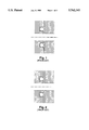
- FIG. 1 is a cross-sectional view of the interface between two segments of solid material having a bore therethrough and sealed by the prior art method of inserting an O-ring into an annular groove having a rectangular cross-section (for the purpose of clarity, the mating faces are shown as being slightly separated one from the other);
- FIG. 2 is a cross-sectional view of the interface similar to the one in FIG. 1, showing a prior art dovetail groove being used to retain the O-ring;
- FIG. 3 is a cross-sectional view of the interface between two segments of solid material having a bore therethrough, sealed by an O-ring which is retained by an O-ring insert according to a preferred embodiment of the present invention ;
- FIG. 4 is an axonometric view, partially in cross-section, of the O-ring insert of FIG. 3 according to the preferred embodiment of the present invention.
- FIGS. 5a-5e are cross-sectional views illustrating a method of re-establishing a seal where the area of the grooved mating face between the bore and the annular groove has been destroyed due to a corrosive and/or abrasive action of fluid.
- the present invention in one of its aspects, comprises an insert or bushing for use in providing a seal at the junction of two axially aligned bores extending through the interface of two segments of solid material.
- segments 2 and 3 represent plates of a mould used in the injection moulding industry.
- the mould is typically manufactured of steel, stainless steel or aluminum, although other materials can be used.
- a bore 1 extends through adjacent segments 2 and 3 of the modular mould.
- the mating face of the segment 2 is provided, co-axially with the bore 1, with a first recess 4, extending inwardly from the mating face, and a second recess 5, extending inwardly from the bottom of the first recess 4.
- Both recesses 4 and 5 are preferably cylindrical, having substantially rectangular cross-sections.
- the recesses 4 and 5 can be bored in the segment 2 using a simple drilling operation.
- the second recess 5 has a diameter greater than the diameter of the bore 1 and the first recess 4 has a diameter greater than the diameter of the second recess 5.
- FIG. 4 illustrates in more detail the O-ring insert in accordance with the preferred embodiment of the invention.
- the insert 7 is uniformly bored and comprises a shoulder or retaining portion 8 and a stem portion 9.
- the inner diameter of the insert 7 is substantially equal to the diameter of the bore 1.
- the shoulder or retaining portion 8 of the insert 7 has a length substantially equal to or less than the depth of the first recess 4, a substantially flat end face, and an outer surface of a substantially frusto-conical or obconic shape.
- the diameter of the retaining portion 8 at or near the end face is greater than the inner diameter of the O-ring 6, and the diameter of the retaining portion 8 adjacent the stem portion 9 is substantially equal to the outer diameter of the stem portion 9 and the diameter of the second recess 5.
- the expression "frusto-conical” is intended to include frusto-conical and toroidal shapes, or a combination of frusto-conical and toroidal shapes, etc.
- the stem portion 9 of the inert 7 preferably has a length substantially equal to or greater than the depth of the second recess 5 and an outer surface of a substantially cylindrical shape.
- the outer diameter of the stem portion 9 is substantially equal to or just slightly greater than the diameter of the second recess 5 such that the stem portion can be retained by a slight press fit against the generally rough walls of the bore 1.
- the stem can also be slightly tapered so as to allow for an easier initial insertion of the insert 7 into the second recess 5.
- the insert 7 is manufactured of a substantially rigid material.
- the choice of material depends upon the properties of the fluid being delivered through the bore 1 and the temperature of the mould. In many instances, an inexpensive stable plastic material such as, for example, nylon 6, PVC, polypropylene, ABS, etc., will be used. If the fluid is aggressive, or if higher mould temperatures are required, the insert may be manufactured of polytetrafluoroethylene (Teflon®). Insert 7 will typically be installed in the second recess 5 manually and retained therein by frictional forces between the recess and insert surfaces Other methods of securing the insert 7 inside the second recess 5 may also be employed and include use of sealants and adhesives, threaded or bayonet-type engagement, etc. Such other methods are generally more complicated and expensive and will be used only if a particularly strong engagement is required.
- the O-ring insert may also be manufactured of metal.
- metal may be the same as the metal used for the manufacture of the blocks or segments, or may comprise another compatible, readily machineable metallic material.
- the O-ring 6 has an outer diameter substantially equal to the diameter of the first recess 4, an inner diameter equal to or greater than the diameter of the second recess 5, and a cross-sectional diameter greater than the depth of the first recess 4.
- the O-ring is typically manufactured of a resilient synthetic material such as neoprene, silicone rubber, polyethylene, etc.
- the present invention provides a device for use in providing a seal at the junction of two axially aligned bores extending through the interface of two segments of solid material.
- the device comprises an O-ring in co-operation with an O-ring insert as described in greater detail above.
- the present invention discloses a method of providing a seal at the junction of co-axial bores extending through two segments of solid material having generally flat mating faces.
- the method comprises drilling in one of the bores, at one of the mating faces, a first recess 4.
- the first recess 4 is co-axial with the bore 1 and has a diameter greater than the diameter of the bore 1.
- the cross-section of the first recess 4 is of a simple, substantially rectangular shape, the drilling is performed in a single operation using conventional tools.
- the second co-axial recess 5 is drilled.
- the second recess 5 extends from the bottom of the first recess 4 and has a diameter greater than the diameter of the bore 1 but smaller than the diameter of the first recess 4. The drilling is again performed in a single operation using conventional tools.
- the method further comprises providing an O-ring 6 and an O-ring insert 7 as disclosed above, installing the insert 7 into the second recess 5, retainably inserting the O-ring 6 into the annular groove defined by the surfaces of the first recess 4 and the outer surface of the retaining portion 8 of the insert 7, and bringing the mating faces of segments 2 and 3 together.
- the present invention comprises a method of re-establishing a seal at the junction of co-axial bores extending through two segments of solid material having generally flat mating faces.
- the area of the mating face between the bore and the annular groove may be corroded, "washed away” or otherwise destroyed by the corrosive or abrasive action of the fluid being delivered through the bore.
- the deterioration process may be accelerated if the rough surface, variations in bore diameter and possible spacing between the mating faces result in the turbulent flow of the fluid.
- FIGS. 5a-5e the area between the bore and an original annular groove of a substantially rectangular cross-sectional shape (FIG. 5a) has been destroyed over time (FIG.5b).
- the preferred method of re-establishing a proper seal involves milling away the affected area and drilling, co-axially with the bore, a recess of a diameter equal to or greater than the inner diameter of the original annular groove (FIG. 5c).
- the method further comprises providing an O-ring insert and an O-ring, both of which are described in detail above.
- the insert is thereafter installed in the recess (FIG. 5d), the O-ring is retainably inserted into the new annular groove defined by the remaining surfaces of the original annular groove and the retaining portion of the insert (FIG. 5e), and the mating faces are brought together.
Abstract
Description
Claims (10)
Priority Applications (1)
| Application Number | Priority Date | Filing Date | Title |
|---|---|---|---|
| US08/782,914 US5762341A (en) | 1997-01-13 | 1997-01-13 | O-ring insert |
Applications Claiming Priority (1)
| Application Number | Priority Date | Filing Date | Title |
|---|---|---|---|
| US08/782,914 US5762341A (en) | 1997-01-13 | 1997-01-13 | O-ring insert |
Publications (1)
| Publication Number | Publication Date |
|---|---|
| US5762341A true US5762341A (en) | 1998-06-09 |
Family
ID=25127575
Family Applications (1)
| Application Number | Title | Priority Date | Filing Date |
|---|---|---|---|
| US08/782,914 Expired - Fee Related US5762341A (en) | 1997-01-13 | 1997-01-13 | O-ring insert |
Country Status (1)
| Country | Link |
|---|---|
| US (1) | US5762341A (en) |
Cited By (7)
| Publication number | Priority date | Publication date | Assignee | Title |
|---|---|---|---|---|
| EP0890773A2 (en) * | 1997-07-07 | 1999-01-13 | K.K.P. KONSTRUKTIVE KUNSTSTOFF-PRODUKTE HANDELSGESELLSCHAFT mbH | Fluid connector with an O-ring retaining device and a method of making an O-ring retaining device in a fluid connector |
| US20060021573A1 (en) * | 2004-06-28 | 2006-02-02 | Cambridge Nanotech Inc. | Vapor deposition systems and methods |
| WO2010043202A2 (en) * | 2008-10-15 | 2010-04-22 | Ixetic Hückeswagen Gmbh | Vacuum pump |
| US20140086809A1 (en) * | 2008-09-25 | 2014-03-27 | Brian Harrison | Dual vessel reactor |
| US9403136B2 (en) | 2008-09-25 | 2016-08-02 | Rubreco Inc. | Dual vessel reactor |
| US20160377178A1 (en) * | 2015-06-25 | 2016-12-29 | Evolution Engineering Inc. | Method for sealing a gap sub assembly |
| US20190128451A1 (en) * | 2017-10-30 | 2019-05-02 | CNN Industrial America, LLC | Sealing assembly with retention sleeve for fluid conduit connector |
Citations (15)
| Publication number | Priority date | Publication date | Assignee | Title |
|---|---|---|---|---|
| US672598A (en) * | 1901-01-11 | 1901-04-23 | Warren Francis Drew | Pipe-coupling. |
| DE1003674B (en) * | 1955-06-30 | 1957-03-07 | Dowty Seals Ltd | Sealing device, especially for hydraulically operated pit rams |
| US3007600A (en) * | 1958-01-27 | 1961-11-07 | Thompson Ramo Wooldridge Inc | Seal |
| US3249372A (en) * | 1963-12-30 | 1966-05-03 | New London Turnpike | Cylinder valve outlet connection |
| US3262722A (en) * | 1964-11-19 | 1966-07-26 | United Aircraft Prod | Coupling having an o-ring retainer |
| US3300225A (en) * | 1964-10-20 | 1967-01-24 | Koppers Co Inc | Extrusion protected resilient rod seal |
| US3425716A (en) * | 1967-03-16 | 1969-02-04 | Fritz R Blau | Glass union |
| US3442515A (en) * | 1966-09-06 | 1969-05-06 | Weatherhead Co | Opposed face non-extrusion seal |
| US3664674A (en) * | 1970-04-22 | 1972-05-23 | Dresser Ind | Split housing with improved seal |
| US3693986A (en) * | 1969-10-25 | 1972-09-26 | John Walkinshaw Lambie | Sealing devices |
| US3698728A (en) * | 1971-01-07 | 1972-10-17 | Mc Donnell Douglas Corp | Fluid sealing device |
| US3854735A (en) * | 1972-10-24 | 1974-12-17 | Exxon Production Research Co | Static face seal |
| US4034993A (en) * | 1974-11-27 | 1977-07-12 | Mitsui Shipbuilding And Engineering Co., Ltd. | Sealing apparatus |
| US4798481A (en) * | 1986-01-24 | 1989-01-17 | Ina Walzlager Schaeffler Kg | Rolling bearing slewing ring |
| US4843187A (en) * | 1988-02-05 | 1989-06-27 | Qualitrol Corporation | Gasket assembly and electrical power transformer including the same |
-
1997
- 1997-01-13 US US08/782,914 patent/US5762341A/en not_active Expired - Fee Related
Patent Citations (15)
| Publication number | Priority date | Publication date | Assignee | Title |
|---|---|---|---|---|
| US672598A (en) * | 1901-01-11 | 1901-04-23 | Warren Francis Drew | Pipe-coupling. |
| DE1003674B (en) * | 1955-06-30 | 1957-03-07 | Dowty Seals Ltd | Sealing device, especially for hydraulically operated pit rams |
| US3007600A (en) * | 1958-01-27 | 1961-11-07 | Thompson Ramo Wooldridge Inc | Seal |
| US3249372A (en) * | 1963-12-30 | 1966-05-03 | New London Turnpike | Cylinder valve outlet connection |
| US3300225A (en) * | 1964-10-20 | 1967-01-24 | Koppers Co Inc | Extrusion protected resilient rod seal |
| US3262722A (en) * | 1964-11-19 | 1966-07-26 | United Aircraft Prod | Coupling having an o-ring retainer |
| US3442515A (en) * | 1966-09-06 | 1969-05-06 | Weatherhead Co | Opposed face non-extrusion seal |
| US3425716A (en) * | 1967-03-16 | 1969-02-04 | Fritz R Blau | Glass union |
| US3693986A (en) * | 1969-10-25 | 1972-09-26 | John Walkinshaw Lambie | Sealing devices |
| US3664674A (en) * | 1970-04-22 | 1972-05-23 | Dresser Ind | Split housing with improved seal |
| US3698728A (en) * | 1971-01-07 | 1972-10-17 | Mc Donnell Douglas Corp | Fluid sealing device |
| US3854735A (en) * | 1972-10-24 | 1974-12-17 | Exxon Production Research Co | Static face seal |
| US4034993A (en) * | 1974-11-27 | 1977-07-12 | Mitsui Shipbuilding And Engineering Co., Ltd. | Sealing apparatus |
| US4798481A (en) * | 1986-01-24 | 1989-01-17 | Ina Walzlager Schaeffler Kg | Rolling bearing slewing ring |
| US4843187A (en) * | 1988-02-05 | 1989-06-27 | Qualitrol Corporation | Gasket assembly and electrical power transformer including the same |
Cited By (15)
| Publication number | Priority date | Publication date | Assignee | Title |
|---|---|---|---|---|
| EP0890773A3 (en) * | 1997-07-07 | 2000-05-10 | KKP Rapid GmbH & Co KG | Fluid connector with an O-ring retaining device and a method of making an O-ring retaining device in a fluid connector |
| EP0890773A2 (en) * | 1997-07-07 | 1999-01-13 | K.K.P. KONSTRUKTIVE KUNSTSTOFF-PRODUKTE HANDELSGESELLSCHAFT mbH | Fluid connector with an O-ring retaining device and a method of making an O-ring retaining device in a fluid connector |
| US8202575B2 (en) | 2004-06-28 | 2012-06-19 | Cambridge Nanotech, Inc. | Vapor deposition systems and methods |
| US20060021573A1 (en) * | 2004-06-28 | 2006-02-02 | Cambridge Nanotech Inc. | Vapor deposition systems and methods |
| US9556519B2 (en) | 2004-06-28 | 2017-01-31 | Ultratech Inc. | Vapor deposition systems and methods |
| US20140086809A1 (en) * | 2008-09-25 | 2014-03-27 | Brian Harrison | Dual vessel reactor |
| US9403136B2 (en) | 2008-09-25 | 2016-08-02 | Rubreco Inc. | Dual vessel reactor |
| US9649612B2 (en) * | 2008-09-25 | 2017-05-16 | Rubreco Inc. | Dual vessel reactor |
| US9901890B2 (en) | 2008-09-25 | 2018-02-27 | Rubreco Inc. | Dual vessel reactor |
| WO2010043202A3 (en) * | 2008-10-15 | 2010-12-23 | Ixetic Hückeswagen Gmbh | Vacuum pump with a sealed accommodation of lubricant |
| WO2010043202A2 (en) * | 2008-10-15 | 2010-04-22 | Ixetic Hückeswagen Gmbh | Vacuum pump |
| US20160377178A1 (en) * | 2015-06-25 | 2016-12-29 | Evolution Engineering Inc. | Method for sealing a gap sub assembly |
| US10295060B2 (en) * | 2015-06-25 | 2019-05-21 | Evolution Engineering Inc. | Method for sealing a gap sub assembly |
| US20190128451A1 (en) * | 2017-10-30 | 2019-05-02 | CNN Industrial America, LLC | Sealing assembly with retention sleeve for fluid conduit connector |
| US10711926B2 (en) * | 2017-10-30 | 2020-07-14 | CNN Industrial America LLC | Sealing assembly with retention sleeve for fluid conduit connector |
Similar Documents
| Publication | Publication Date | Title |
|---|---|---|
| US5174611A (en) | Releasable coupling for air carrying tubes | |
| US4477055A (en) | Valve seat for ball valves | |
| US5762341A (en) | O-ring insert | |
| EP0950815A2 (en) | Piston and diaphragm for a reciprocating pump | |
| KR19980701256A (en) | Coupling Valve Assembly | |
| US4094520A (en) | Self centering flange gasket assembly | |
| KR101889732B1 (en) | Plastic seal fitting | |
| US3003493A (en) | Core drill adapter | |
| US20020070544A1 (en) | Universal interlocking fitting | |
| KR20050065454A (en) | Pipe repair system and device | |
| CA2258460C (en) | Replaceable valve seat | |
| NL8103425A (en) | DETACHABLE PIPE COUPLING AND ITS MANUFACTURE. | |
| US5752814A (en) | Plunger and seal for well pump | |
| EP1281908B1 (en) | A coupling | |
| WO2017003516A1 (en) | Fluid level verification apparatus | |
| MXPA03001475A (en) | Quick-release fitting assembly. | |
| CA2185793A1 (en) | Sealing means for slide plate screen changer | |
| US4050700A (en) | Seal having fluent packing material | |
| US20070007764A1 (en) | Connections for tubing and method of connecting tubing segments | |
| JP2016161032A (en) | Connector member for pipe passage block connection and its manufacturing method | |
| US4285896A (en) | Isostatic molding process and seal | |
| US3087232A (en) | Method of manufacturing valve seat | |
| EP0145137A2 (en) | Heating apparatus | |
| US3462176A (en) | Rotatable coupling with passages | |
| GB2375149A (en) | A gasket |
Legal Events
| Date | Code | Title | Description |
|---|---|---|---|
| AS | Assignment |
Owner name: ZYGO MOULD LIMITED, CANADA Free format text: ASSIGNMENT OF ASSIGNORS INTEREST;ASSIGNOR:WRIGHT, JOHN BENNISON;REEL/FRAME:008355/0101 Effective date: 19970107 |
|
| FEPP | Fee payment procedure |
Free format text: PAT HOLDER NO LONGER CLAIMS SMALL ENTITY STATUS, ENTITY STATUS SET TO UNDISCOUNTED (ORIGINAL EVENT CODE: STOL); ENTITY STATUS OF PATENT OWNER: LARGE ENTITY |
|
| REFU | Refund |
Free format text: REFUND - PAYMENT OF MAINTENANCE FEE, 4TH YR, SMALL ENTITY (ORIGINAL EVENT CODE: R283); ENTITY STATUS OF PATENT OWNER: LARGE ENTITY |
|
| AS | Assignment |
Owner name: HUSKY INJECTION MOLDING SYSTEMS LTD., CANADA Free format text: ASSIGNMENT OF ASSIGNORS INTEREST;ASSIGNOR:QUINNEY & ASSOCIATES LTD.;REEL/FRAME:012177/0326 Effective date: 20010821 |
|
| FPAY | Fee payment |
Year of fee payment: 4 |
|
| REMI | Maintenance fee reminder mailed | ||
| LAPS | Lapse for failure to pay maintenance fees | ||
| LAPS | Lapse for failure to pay maintenance fees |
Free format text: PATENT EXPIRED FOR FAILURE TO PAY MAINTENANCE FEES (ORIGINAL EVENT CODE: EXP.); ENTITY STATUS OF PATENT OWNER: LARGE ENTITY |
|
| STCH | Information on status: patent discontinuation |
Free format text: PATENT EXPIRED DUE TO NONPAYMENT OF MAINTENANCE FEES UNDER 37 CFR 1.362 |
|
| FP | Lapsed due to failure to pay maintenance fee |
Effective date: 20060609 |
|
| AS | Assignment |
Owner name: THOMAS, BRUCE A., CANADA Free format text: GENERAL SECURITY AGREEMENT;ASSIGNOR:ZYGO MOULD, LIMITED;REEL/FRAME:045417/0121 Effective date: 19971117 |