EP2345472A2 - Verbindungsklammer für Spielbausteine und Bausatz - Google Patents
Verbindungsklammer für Spielbausteine und Bausatz Download PDFInfo
- Publication number
- EP2345472A2 EP2345472A2 EP10014030A EP10014030A EP2345472A2 EP 2345472 A2 EP2345472 A2 EP 2345472A2 EP 10014030 A EP10014030 A EP 10014030A EP 10014030 A EP10014030 A EP 10014030A EP 2345472 A2 EP2345472 A2 EP 2345472A2
- Authority
- EP
- European Patent Office
- Prior art keywords
- clamping
- clamping portions
- connecting clip
- portions
- web portion
- Prior art date
- Legal status (The legal status is an assumption and is not a legal conclusion. Google has not performed a legal analysis and makes no representation as to the accuracy of the status listed.)
- Granted
Links
- 238000010276 construction Methods 0.000 title 1
- 239000004952 Polyamide Substances 0.000 claims abstract description 7
- 229920002647 polyamide Polymers 0.000 claims abstract description 7
- 239000004677 Nylon Substances 0.000 claims abstract description 4
- 229920001778 nylon Polymers 0.000 claims abstract description 4
- 229920002725 thermoplastic elastomer Polymers 0.000 claims abstract description 4
- 239000004033 plastic Substances 0.000 claims description 8
- 239000000463 material Substances 0.000 claims description 7
- 239000011449 brick Substances 0.000 claims description 6
- 238000003892 spreading Methods 0.000 claims description 5
- 230000005489 elastic deformation Effects 0.000 claims description 4
- 238000002347 injection Methods 0.000 description 2
- 239000007924 injection Substances 0.000 description 2
- 239000004922 lacquer Substances 0.000 description 2
- 238000004519 manufacturing process Methods 0.000 description 2
- 238000004381 surface treatment Methods 0.000 description 2
- 239000002023 wood Substances 0.000 description 2
- 239000002131 composite material Substances 0.000 description 1
- 238000005520 cutting process Methods 0.000 description 1
- 238000006073 displacement reaction Methods 0.000 description 1
- 238000005553 drilling Methods 0.000 description 1
- 230000000694 effects Effects 0.000 description 1
- 239000013013 elastic material Substances 0.000 description 1
- 229920001971 elastomer Polymers 0.000 description 1
- 239000000806 elastomer Substances 0.000 description 1
- 239000000835 fiber Substances 0.000 description 1
- 238000000227 grinding Methods 0.000 description 1
- 238000003801 milling Methods 0.000 description 1
- 239000003973 paint Substances 0.000 description 1
- 230000002093 peripheral effect Effects 0.000 description 1
- 239000011295 pitch Substances 0.000 description 1
- 230000003763 resistance to breakage Effects 0.000 description 1
- 238000007493 shaping process Methods 0.000 description 1
- 230000003068 static effect Effects 0.000 description 1
Images
Classifications
-
- A—HUMAN NECESSITIES
- A63—SPORTS; GAMES; AMUSEMENTS
- A63H—TOYS, e.g. TOPS, DOLLS, HOOPS OR BUILDING BLOCKS
- A63H33/00—Other toys
- A63H33/04—Building blocks, strips, or similar building parts
- A63H33/10—Building blocks, strips, or similar building parts to be assembled by means of additional non-adhesive elements
- A63H33/107—Building blocks, strips, or similar building parts to be assembled by means of additional non-adhesive elements using screws, bolts, nails, rivets, clamps
Definitions
- the present invention relates to a connection clip for toy building blocks and a kit with at least two toy blocks, which are interconnected by at least one connection bracket.
- the present invention relates to a connecting bracket for wooden toy blocks and a kit comprising at least two wooden toy blocks.
- Wooden toy blocks for children in kindergarten and primary school age have been known for many decades.
- cuboid wooden toy blocks nowadays related kits are manufactured and sold with increasingly complex wooden toy blocks.
- arcuate wooden toy blocks and roof pitches for house kits or track sections for ball track kits are mentioned here.
- Wooden toy blocks are produced industrially by means of cutting shaping processes, in particular by means of sawing, drilling and milling. In order not to injure particularly sensitive children's hands by projecting wood chips or wood splinters, special attention is paid in the production of wooden toy blocks of the final surface treatment, in particular the rounding of edges and the surface grinding of side surfaces.
- the final surface treatment, and possibly the paint, cause stacked toy bricks are slightly displaced by lateral force to each other, which can lead to the collapse of the structure.
- connection clip for toy building blocks in particular wooden toy blocks, with at least two opposing clamping portions, each of which has a narrow and a wide end, wherein the two clamping portions are spaced at their wide ends for receiving at least two toy bricks, and are connected together at their narrow ends by at least one web portion.
- each of the clamping portions includes a substantially right angle with the web portion.
- connection clip can be slid onto the toy building block in a simple manner in order to connect adjoining toy building blocks with one another.
- the fact that the web portion connects the narrow ends of the clamping portions together, the free, wide ends of the clamping portions can be used to connect game blocks, for example, also over corner.
- each of the clamping portions on two wing portions which together in the region of the narrow end an angle of 45 ° to 135 °, preferably from 60 ° to 120 °, in particular preferably from 90 °.
- the two wing regions of the respective clamping section are of equal length.
- each of the clamping portions is formed substantially as a trapezoid having a narrow and a wide base side. This shape is easy to manufacture and gives the interconnected game blocks sufficient stability.
- connection bracket can thus be pushed under elastic deformation of the web portion on the game modules.
- the wide ends of the clamping portions preferably the wing portions, each with respect to the web portion on an outwardly facing spreading.
- a material of the web portion, z. B. Plyamid, a sufficient elasticity and relatively greater hardness and breaking strength to produce a high clamping force as a material of the clamping portions, z. B. TPE.
- the clamping sections have greater adhesion or adherence to the surfaces of the toy building blocks to be joined and consist of injection-moldable thermoelastic plastic, such as thermoelastic elastomer (TPE).
- the web portion is formed of a different plastic than the clamping portions.
- the web portion at its ends on projections which protrude into the narrow ends of the clamping portions.
- kit in particular a ball track, with at least two toy bricks, in particular wooden toy blocks, which are connected to each other by at least one connection clip according to at least one of the aforementioned embodiments.
- the toy bricks have a width that is slightly greater than a distance between opposing inner sides of the clamping portions in a relaxed state of the connecting bracket.
- the connecting clip is preferably connected to the toy building blocks by elastic deformation of the web section and / or of the clamping sections.
- connection clip 1 In the FIGS. 1 to 3 an embodiment of a connection clip 1 is shown in different views.
- the connection clip 1 has two clamping sections 2 opposite one another, which are connected to one another by means of a web section 3.
- the web portion 3 extends in the transverse direction of the connecting clip 1. It is also possible that a plurality of web portions 3 in the transverse direction of the connecting clip 1 parallel to each other.
- Each of the clamping portions 2 has a free end, which is opposite to the end of the clamping portion 2, on which the clamping portion 2 is connected to the web portion 3. Between the transverse in the transverse direction of the connecting bracket 1 opposite free ends of the clamping portions 2, a receiving portion of the connecting clip 1 is defined.
- each of the clamping portions 2 has a narrow end 2a and an opposite, wide end 2b. At their narrow ends 2a opposite in the transverse direction of the connecting clip 1 clamping portions 2 are connected to each other by means of the web portion 3. Accordingly, the wide ends 2b, the free ends of the clamping portions 2, and the connection bracket 1 are. The wide ends 2b are spaced apart for receiving at least one, preferably at least two toy building blocks 11, 12.
- each of the clamping portions 2 has a substantially trapezoidal basic shape, the wide end 2b having a base of the trapezoid, i. forms the longer of the two parallel bases of the trapezoid. Accordingly, the narrow end 2a of the clamping portion 2 forms the shorter of the two bases of the trapezoid.
- the legs of the trapezoid are preferably formed equal length.
- each of the clamping portions 2 at least two wing portions 4, which form the legs of the substantially trapezoidal clamping portion 2.
- a substantially triangular recess is preferably provided between the two wing regions 4.
- the two wing portions 4 of the respective clamping portion 2 are the same length. In particular, it is advantageous if all four wing areas 4 of the connecting clip 1 are the same length.
- the wing portions 4 close in the vicinity of the narrow end 2a of the respective clamping portion 2 an angle ⁇ .
- the angle ⁇ extends in a range of 45 ° to 135 °. Preferably, this range is between 60 ° and 120 °. Particularly preferably, the two wing regions 4 enclose an angle ⁇ of 90 °.
- the clamping portions 2 of the connecting bracket 1 a different basic shape than the trapezoidal basic shape exhibit.
- the opposing clamping portions 2 are formed semicircular or U-shaped.
- an oval or circular basic shape is possible.
- the web section 3 does not necessarily have to be connected to the narrow end 2a of the clamping section 2, but may also extend, for example, between middle regions of the opposing clamping sections 2 in the transverse direction of the connecting clip 1.
- these preferably have a semicircular contour.
- the contour between the two wing regions 4, i. the region in which the wing regions 4 adjoin one another is preferably rounded, and in particular preferably formed as a quarter of a circular path when the wing regions 4 enclose an angle ⁇ of 90 °.
- the wing regions 4 preferably have spreads 5, which relative to the web section 3, i. in the transverse direction of the connecting bracket 1, facing outward.
- the outwardly pointing spreading 5 serve as a guide when the connecting bracket 1 is pushed onto the game or the blocks 11, 12.
- the spreads 5 ensure that the connecting clip 1 is preferably bent apart when pushed onto the toy building blocks 11, 12 or continuously in its elastic region.
- inner sides of the clamping sections 2, i. the side of the respective clamping portion 2, which comes into contact with a corresponding outer surface of the toy building block or with corresponding outer surfaces of the toy building blocks 11, 12, is not continuous planar.
- the inner sides of the clamping sections 2 it is possible for the inner sides of the clamping sections 2 to have a peripheral shoulder in an area close to the edge, the inner area of the clamping sections 2 being slightly raised on the inner sides compared with the edge area of the clamping sections 2, i. in the transverse direction of the connecting bracket 1 protrudes slightly inward.
- other configurations of the inner sides of the clamping portions 2 are possible.
- the clamping portions 2 include at their narrow ends 2a with the web portion 3 at a substantially right angle ⁇ .
- the web section 3 has a slight curvature in the transverse direction of the connecting clip 1.
- this curvature is convex, ie curved relative to the connection bracket 1 to the outside.
- the web portion 3 is concave, ie bulges between the clamping portions 2.
- the angle ⁇ between the respective clamping portion 2 and the respective end of the web portion 3 is 90 °.
- the web section 3 straight. Then it is advantageous if the angle ⁇ between the respective clamping portion 2 and the respective end of the web portion 3 has an angle of less than 90 °.
- the curvature and the angle ⁇ cause the inner sides of the clamping portions 2 in a region between the web portion 3 and the spreaders 5 are inclined slightly into the receiving space.
- the web portion 3 is provided with a curvature, and the angle ⁇ are formed smaller than 90 °.
- the web portions 3 in the transverse direction of the connecting clip 1 at their outer ends projections 6 which at least partially protrude into the clamping portions 2.
- these projections 6 have shoulders and / or undercuts, and / or, for example, by material of the clamping portions 2 are cohesively surrounded.
- the projections 6 of the web section 3 can be at least partially encapsulated by a plastic of the clamping sections 2.
- connection clip 1 is preferably made as an injection molded part and is preferably made of elastic material.
- the clamping sections 2, which are preferably made of TPE, are preferably injection-molded onto the web section of nylon or polyamide (PA) inserted in the injection mold.
- PA nylon or polyamide
- the connection clip 1 may alternatively be made in several parts and by a joint connection between the clamping and web sections.
- the material of the web portion 3 has a relatively high resistance to breakage, with sufficient elasticity and in relation to the clamping portions 2 of greater hardness to produce a high clamping force on.
- the clamping sections 2 in turn preferably have a greater adhesion or rubber-elastic adhesiveness (higher static friction) than the web section 3 with the surfaces of the toy building blocks 11, 12 to be joined.
- the clamping portions 2 are preferably formed of a different plastic than the web portion 3.
- the clamping portions 2 made of a relatively soft plastic, such as sprayable thermoplastic elastomers (TPE) with good adhesion to the surfaces of the game building blocks 11, 12 to be joined.
- TPE sprayable thermoplastic elastomers
- the web section 3 consists for example of nylon or polyamide (PA).
- connection clip 1 from other materials, including fiber composites.
- FIGS. 4 to 6 are ways of connecting two game blocks 11, 12, preferably two wooden toy blocks, shown by way of example.
- a cuboid, first toy building block 11 of a kit 10 is shown lying.
- a cube-shaped, second game module 12 of the kit 10 is placed on the first game module 11.
- the two game blocks 11, 12 are thus arranged in the form of a horizontal L.
- FIGS. 4 and 5 is shown a first way, these two game blocks 11, 12 through the connection bracket 1 from the FIGS. 1 to 3 to connect with each other.
- the web section of the pushed-on connection clip 1 lies flat on outer surfaces of the toy building blocks 11, 12 in the vicinity of the joint of the two toy building blocks 11, 12.
- Fig. 6 the two game blocks 11,12 are connected to each other over corner.
- the web portion 3 of the pushed-connection clamp 1 forms an angle of about 45 ° to the respective adjacent surfaces of the toy building blocks 11, 12.
- the wing portions 4 of the clamping portions 2 of the connecting bracket 1 are accordingly parallel or at right angles to the joint of the two game building blocks 11, 12 or to the surfaces with which the two game building blocks 11, 12 touch each other.
- the toy building blocks 11, 12 preferably have a uniform width, which is slightly larger than a distance between the opposite inner sides of the clamping portions 2 in the relaxed state of the connecting clip 1.
- wooden toy blocks preferably have a uniform width of 40 mm.
- other, uniform widths are possible.
- connection clip 1 Due to the elastic properties of the connection clip 1, it is possible to solve this in a simple manner again from the toy building blocks 11, 12 when the kit 10 is to be disassembled or changed.
- the preceding embodiments relate to a connecting bracket 1 for toy building blocks 11, 12, in particular wooden toy blocks, with at least two opposing clamping portions 2, each of which has a narrow and a wide end 2a, 2b.
- the two clamping portions 2 are spaced at their wide ends 2b for receiving at least two toy building blocks 11, 12.
- the clamping portions 2 are interconnected by at least one web portion 3, with which each of the clamping portions 2 includes a substantially right angle ⁇ .
- kit 10 for example a ball track or a building, with at least two toy building blocks 11, 12, in particular wooden toy blocks, which are detachably connected to one another by at least one of the previously described connection clips 1.
Landscapes
- Toys (AREA)
Abstract
Description
- Die vorliegende Erfindung betrifft eine Verbindungsklammer für Spielbausteine und einen Bausatz mit zumindest zwei Spielbausteinen, die durch zumindest eine Verbindungsklammer miteinander verbunden sind. Insbesondere betrifft die vorliegende Erfindung eine Verbindungsklammer für Holzspielklötze und einen Bausatz mit zumindest zwei Holzspielklötzen.
- Holzspielklötze für Kinder im Kindergarten- und Grundschulalter sind seit vielen Jahrzehnten bekannt. Neben den ursprünglichen, quaderförmigen Holzspielklötzen werden heutzutage themenbezogene Bausätze mit zunehmend komplexeren Holzspielklötzen hergestellt und verkauft. Beispielsweise seien hier bogenförmige Holzspielklötze und Dachschrägen für Häuserbausätze oder Bahnabschnitte für Kugelbahn-Bausätze genannt.
- Holzspielklötze werden industriell mit spanenden Formgebungsverfahren, insbesondere mittels Sägen, Bohren und Fräsen hergestellt. Um gerade empfindliche Kinderhände nicht durch vorstehende Holzspäne oder Holzsplitter zu verletzen, gilt ein besonderes Augenmerk bei der Herstellung von Holzspielklötzen der abschließenden Oberflächenbearbeitung, insbesondere dem Verrunden von Kanten und dem Planschleifen von Seitenflächen.
- Anschließend ist es möglich, die Oberflächen der Holzspielklötze zusätzlich durch Klarlack oder farbige Lacke zu versiegeln. Ein Großteil der Holzspielklötze wird jedoch im unlackierten Zustand genutzt.
- Die abschließende Oberflächenbearbeitung, und ggf. die Lackierung, führen dazu, dass aufeinander gestapelte Spielbausteine durch seitliche Krafteinwirkung leicht zueinander verschiebbar sind, was zum Einsturz des Bauwerks führen kann. Insbesondere bei qualitativ hochwertigen Holzspielklötzen treten kaum Verzahnungseffekte zwischen den plan geschliffenen, einander angrenzenden Oberflächen zweier oder mehrerer aufeinander gestapelter Bausteine auf.
- Somit sind insbesondere hohe Bauwerke, wie Türme oder Kugelbahnen aus Holzspielklötzen leicht zum Einsturz zu bringen, ohne dass dies vom Anwender beabsichtigt ist.
- Es ist daher Aufgabe der vorliegenden Erfindung, eine einfache Möglichkeit zu schaffen, die Bausteine relativ zueinander zu fixieren, sowie einen entsprechenden Bausatz anzugeben.
- Erfindungsgemäß gelöst wird diese Aufgabe durch eine Verbindungsklammer für Spielbausteine, insbesondere Holzspielklötze, mit zumindest zwei einander gegenüberliegenden Klemmabschnitten, von denen jeder ein schmales und ein weites Ende aufweist, wobei die beiden Klemmabschnitte an ihren weiten Enden zur Aufnahme von zumindest zwei Spielbausteinen beabstandet sind, und an ihren schmalen Enden durch zumindest einen Stegabschnitt miteinander verbunden sind. Vorzugsweise schließt jeder der Klemmabschnitte einen im wesentlichen rechten Winkel mit dem Stegabschnitt ein.
- Durch die zwei einander gegenüberliegenden Klemmabschnitte ist die Verbindungsklammer auf einfache Art und Weise auf die Spielbaustein aufschiebbar, um einander angrenzende Spielbaustein miteinander zu verbinden. Dadurch dass der Stegabschnitt die schmalen Enden der Klemmabschnitte miteinander verbindet, können die freien, weiten Enden der Klemmabschnitte genutzt werden, um Spielbausteine beispielsweise auch über Eck miteinander zu verbinden.
- Vorzugsweise weist jeder der Klemmabschnitte zwei Flügelbereiche auf, die miteinander im Bereich des schmalen Endes einen Winkel von 45° bis 135°, vorzugsweise von 60° bis 120°, insbesondere vorzugsweise von 90°, einschließen.
- Insbesondere ist es von Vorteil, wenn die beiden Flügelbereiche des jeweiligen Klemmabschnitts gleich lang sind.
- Gemäß einem bevorzugten Ausführungsbeispiel ist jeder der Klemmabschnitte im Wesentlichen als Trapez mit einer schmalen und einer weiten Grundseite ausgebildet. Diese Form ist einfach herstellbar und verleiht den miteinander verbundenen Spielbausteinen eine ausreichende Stabilität.
- Insbesondere ist es von Vorteil, wenn der Stegabschnitt zwischen den beiden Klemmabschnitten eine, vorzugsweise konvexe, Krümmung aufweist. Die Verbindungsklammer kann somit unter elastischer Verformung des Stegabschnitts auf die Spielbausteine aufgeschoben werden.
- Gemäß einem besonders bevorzugten Ausführungsbeispiel weisen die weiten Enden der Klemmabschnitte, vorzugsweise die Flügelbereiche, bezogen auf den Stegabschnitt jeweils eine nach außen weisende Aufspreizung auf. Durch diese Aufspreizung an den freien Enden der Klemmabschnitte kann die Verbindungsklammer besonders einfach auf die Spielbausteine aufgeschoben werden, da die Aufspreizung als Führung beim Aufschiebevorgang dient und ein Verkanten der Verbindungsklammer mit den Spielbausteinen verhindert.
- Vorzugsweise weist ein Material des Stegabschnitts, z. B. Plyamid, eine hinreichende Elastizität und verhältnismäßig größere Härte und Bruchfestigkeit zur Erzeugung einer hohen Klemmkraft auf, als ein Material der Klemmabschnitte, z. B. TPE. Insbesondere ist es von Vorteil, wenn die Klemmabschnitte eine größere Anhaftung bzw. Haftfähigkeit an den Oberflächen der zu verbindenden Spielbausteine aufweisen und aus spritzgießfähigem thermoelastischem Kunststoff, wie thermoelastischem Elastomer (TPE), bestehen.
- Weiterhin vorzugsweise ist der Stegabschnitt aus einem anderen Kunststoff als die Klemmabschnitte ausgebildet.
- Gemäß einem bevorzugten Ausführungsbeispiel weist der Stegabschnitt an seinen Enden Vorsprünge auf, die in die schmalen Enden der Klemmabschnitte hineinragen. Hierdurch wird eine zuverlässige Verbindung zwischen dem Stegabschnitt und den angrenzenden Klemmabschnitten erreicht.
- Insbesondere ist es hierzu von Vorteil, wenn die Vorsprünge des Stegabschnitts durch einen Kunststoff der Klemmabschnitte umspritzt sind.
- Die vorgenannte Aufgabe wird ferner erfindungsgemäß gelöst durch einen Bausatz, insbesondere eine Kugelbahn, mit zumindest zwei Spielbausteinen, insbesondere Holzspielklötzen, die durch zumindest eine Verbindungsklammer nach zumindest einem der vorgenannten Ausführungsbeispiele lösbar miteinander verbunden sind.
- Hierdurch wird verhindert, dass der Bausatz ungewollt durch seitliches Verschieben der Spielbausteine zueinander zum Einsturz gebracht wird.
- Vorzugsweise weisen die Spielbausteine eine Breite auf, die geringfügig größer ist als ein Abstand zwischen einander gegenüberliegenden Innenseiten der Klemmabschnitte in einem entspannten Zustand der Verbindungsklammer. Vorzugsweise ist die Verbindungsklammer unter elastischer Verformung des Stegabschnitts und/oder der Klemmabschnitte mit den Spielbausteinen verbunden.
- Die vorliegende Erfindung wird nachfolgend anhand von bevorzugten Ausführungsbeispielen in Verbindung mit den zugehörigen Figuren näher erläutert. In diesen zeigen:
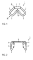
- Fig. 1
- einen Klemmabschnitt einer Verbindungsklammer in einer Seitenansicht,
- Fig. 2
- die Verbindungsklammer aus
Fig. 1 mit ihren einander gegenüberliegenden Klemmabschnitten, - Fig. 3
- die Verbindungsklammer aus
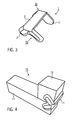
Fig. 1 und 2 in einer perspektivischen Darstellung, - Fig. 4
- einen Bausatz bestehend aus zwei Spielbausteinen, die mittels der Verbindungsklammer aus
Fig. 1 bis 3 verbunden sind, - Fig. 5
- den Bausatz aus
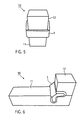
Fig. 4 , wobei ein die beiden Klemmabschnitte verbindender Stegabschnitt plan auf den beiden Spielbausteinen aufliegt, und - Fig. 6
- ein Bausatz, bei dem die beiden Spielbausteine aus
Fig. 4 und5 mittels der Verbindungsklammer ausFig. 1 bis 3 über Eck verbunden sind. - In den
Figuren 1 bis 3 ist ein Ausführungsbeispiel einer Verbindungsklammer 1 in verschiedenen Ansichten gezeigt. Die Verbindungsklammer 1 weist zwei einander gegenüberliegende Klemmabschnitte 2 auf, die mittels eines Stegabschnitts 3 miteinander verbunden sind. Der Stegabschnitt 3 erstreckt sich in Querrichtung der Verbindungsklammer 1. Es ist auch möglich, das mehrere Stegabschnitte 3 in Querrichtung der Verbindungsklammer 1 parallel zueinander verlaufen. - Jeder der Klemmabschnitte 2 weist ein freies Ende auf, das dem Ende des Klemmabschnitts 2 gegenüberliegt, an dem der Klemmabschnitt 2 mit den Stegabschnitt 3 verbunden ist. Zwischen den in Querrichtung der Verbindungsklammer 1 gegenüberliegenden, freien Enden der Klemmabschnitte 2 ist ein Aufnahmebereich der Verbindungsklammer 1 definiert.
- In einem entspannten Zustand der Verbindungsklammer 1 sind die in Querrichtung der Verbindungsklammer 1 gegenüberliegenden, freien Enden der Klemmabschnitte 2 kontaktfrei voneinander beabstandet. In einem vorgespannten Zustand der Verbindungsklammer 1 ist im Aufnahmebereich zwischen den Klemmabschnitten 2 zumindest ein Spielbaustein 11, 12 einklemmbar, worauf mit Bezug auf die
Figuren 4 bis 6 noch eingegangen werden wird. - Im dargestellten Ausführungsbeispiel weist jeder der Klemmabschnitte 2 ein schmales Ende 2a und ein gegenüberliegendes, weites Ende 2b auf. An ihren schmalen Enden 2a sind die in Querrichtung der Verbindungsklammer 1 gegenüberliegenden Klemmabschnitte 2 mittels des Stegabschnitts 3 miteinander verbunden. Dementsprechend stellen die weiten Enden 2b die freien Enden der Klemmabschnitte 2, bzw. der Verbindungsklammer 1 dar. Die weiten Enden 2b sind zur Aufnahme von zumindest einem, vorzugsweise zumindest zwei Spielbausteinen 11, 12 voneinander beabstandet.
- Vorzugsweise weist jeder der Klemmabschnitte 2 eine im Wesentlichen trapezförmige Grundform auf, wobei das weite Ende 2b eine Basis des Trapezes, d.h. die längere der beiden parallelen Grundseiten des Trapezes bildet. Dementsprechend bildet das schmale Ende 2a des Klemmabschnitts 2 die kürzere der beiden Grundseiten des Trapezes. Die Schenkel des Trapezes sind vorzugsweise gleichlang ausgebildet.
- Im dargestellten Ausführungsbeispiel weist jeder der Klemmabschnitte 2 zumindest zwei Flügelbereiche 4 auf, die die Schenkel des im Wesentlichen trapezförmigen Klemmabschnitts 2 bilden. An der Basis des Trapezes ist zwischen den beiden Flügelbereichen 4 vorzugsweise eine im Wesentlichen dreieckige Aussparung vorgesehen. Vorzugsweise sind die beiden Flügelbereiche 4 des jeweiligen Klemmabschnitts 2 gleichlang. Insbesondere ist es von Vorteil, wenn alle vier Flügelbereiche 4 der Verbindungsklammer 1 gleichlang sind.
- Die Flügelbereiche 4 schließen in der Nähe des schmalen Endes 2a des jeweiligen Klemmabschnitts 2 einen Winkel β ein. Der Winkel β erstreckt sich in einem Bereich von 45° bis 135°. Vorzugsweise liegt dieser Bereich zwischen 60° und 120°. Besonders vorzugsweise schließen die beiden Flügelbereiche 4 einen Winkel β von 90° ein.
- Obwohl dies in den
Figuren 1 bis 3 nicht dargestellt ist, können die Klemmabschnitte 2 der Verbindungsklammer 1 auch eine andere Grundform als die trapezförmige Grundform aufweisen. Beispielsweise ist es möglich, dass die einander gegenüberliegenden Klemmabschnitte 2 halbkreisförmig oder U-förmig ausgebildet sind. Ebenso ist eine beispielsweise ovale oder auch kreisförmige Grundform möglich. Der Stegabschnitt 3 muss dabei nicht zwangsläufig mit dem schmalen Ende 2a des Klemmabschnitts 2 verbunden sein, sondern kann sich beispielsweise auch zwischen Mittenbereichen der einander gegenüberliegenden Klemmabschnitte 2 in Querrichtung der Verbindungsklammer 1 erstrecken. - Im Bereich der freien Enden der Flügelbereiche 4 weisen diese vorzugsweise eine halbkreisförmige Kontur auf. Auch die Kontur zwischen den beiden Flügelbereichen 4, d.h. der Bereich, in dem die Flügelbereiche 4 aneinander grenzen, ist vorzugsweise verrundet, und insbesondere vorzugweise als Viertel einer Kreisbahn ausgebildet, wenn die Flügelbereiche 4 einen Winkel β von 90° einschließen.
- An ihren freien Enden weisen die Flügelbereiche 4 vorzugsweise Aufspreizungen 5 auf, die bezogen auf den Stegabschnitt 3, d.h. in Querrichtung der Verbindungsklammer 1, nach außen weisen. Die nach außen weisenden Aufspreizungen 5 dienen als Führung, wenn die Verbindungsklammer 1 auf den oder die Spielbausteine 11, 12 aufgeschoben wird. Insbesondere sorgen die Aufspreizungen 5 dafür, dass die Verbindungsklammer 1 beim Aufschieben auf den oder die Spielbausteine 11, 12 vorzugsweise kontinuierlich in ihrem elastischen Bereich auseinandergebogen wird.
- Um das Aufschieben der Verbindungsklammer 1 auf den oder die Spielbausteine 11, 12 weiter zu erleichtern, ist es von Vorteil, wenn Innenseiten der Klemmabschnitte 2, d.h. die Seite des jeweiligen Klemmabschnitts 2, die mit einer entsprechenden Außenfläche des Spielbausteins oder mit entsprechenden Außenflächen der Spielbausteine 11, 12 in Kontakt kommt, nicht durchgehend planar ist. Beispielsweise ist es möglich, dass die Innenseiten der Klemmabschnitte 2 in einem randnahen Bereich einen umlaufenden Absatz aufweisen, wobei der Innenbereich der Klemmabschnitte 2 im Vergleich zum Randbereich der Klemmabschnitte 2 auf den Innenseiten leicht erhöht ist, d.h. in Querrichtung der Verbindungsklammer 1 leicht nach innen vorspringt. Jedoch sind auch andere Gestaltungen der Innenseiten der Klemmabschnitte 2 möglich.
- Vorzugsweise schließen die Klemmabschnitte 2 an ihren schmalen Enden 2a mit dem Stegabschnitt 3 einen im Wesentlichen rechten Winkel α ein. Im dargestellten Ausführungsbeispiel weist der Stegabschnitt 3 in Querrichtung der Verbindungsklammer 1 eine leichte Krümmung auf. Vorzugsweise ist diese Krümmung konvex ausgebildet, d.h. bezogen auf die Verbindungsklammer 1 nach außen gewölbt. Jedoch ist es auch möglich, dass der Stegabschnitt 3 konkav ausgebildet ist, d.h. sich zwischen die Klemmabschnitte 2 vorwölbt.
- Wenn der Stegabschnitt 3, wie oben erläutert, eine Krümmung aufweist, ist es von Vorteil, wenn der Winkel α zwischen dem jeweiligen Klemmabschnitt 2 und dem jeweiligen Ende des Stegabschnitts 3 90° beträgt.
- Jedoch ist es beispielsweise auch möglich, den Stegabschnitt 3 gerade auszubilden. Dann ist es von Vorteil, wenn der Winkel α zwischen dem jeweiligen Klemmabschnitt 2 und dem jeweiligen Ende des Stegabschnitts 3 einen Winkel von kleiner 90° aufweist.
- In beiden Fällen führen die Krümmung und der Winkel α dazu, dass die Innenseiten der Klemmabschnitte 2 in einem Bereich zwischen dem Stegabschnitt 3 und den Aufspreizungen 5 leicht in den Aufnahmeraum geneigt sind. Um diese Neigung zu erzielen, ist es auch möglich, dass der Stegabschnitt 3 mit einer Krümmung versehen ist, und die Winkel α kleiner als 90° ausgebildet sind.
- Um den Stegabschnitt 3 zuverlässig mit den schmalen Enden 2a der Klemmabschnitte 2 zu verbinden, ist es von Vorteil, wenn die Stegabschnitte 3 in Querrichtung der Verbindungsklammer 1 an ihren äußeren Enden Vorsprünge 6 aufweisen, die zumindest teilweise in die Klemmabschnitte 2 hineinragen. Insbesondere ist es von Vorteil, wenn diese Vorsprünge 6 Absätze und/oder Hinterschneidungen aufweisen, und/oder beispielsweise durch Material der Klemmabschnitte 2 stoffschlüssig umgeben sind. Beispielsweise können die Vorsprünge 6 des Stegabschnitts 3 durch einen Kunststoff der Klemmabschnitte 2 zumindest teilweise umspritzt sein.
- Die gesamte Verbindungsklammer 1 wird vorzugsweise als Spritzgußteil hergestellt und besteht vorzugsweise aus elastischem Material. Vorzugsweise werden die bevorzugt aus TPE bestehenden Klemmabschnitte 2 an den in die Spritzgießform eingelegten Stegabschnitt aus Nylon oder Polyamid (PA) angespritzt. Es wäre jedoch auch möglich, die gesamte Verbindungskammer 1 als ein Mehrkomponenten-Spritzgußteil zu spritzen. Selbstverständlich kann die Verbindungsklammer 1 alternativ mehrteilig und durch eine Fügeverbindung zwischen Klemm- und Stegabschnitten hergestellt sein.
- Vorzugsweise weist das Material des Stegabschnitts 3 eine verhältnismäßig hohe Bruchsicherheit, bei hinreichender Elastizität und im Verhältnis zu den Klemmabschnitten 2 größerer Härte zur Erzeugung einer hohen Klemmkraft, auf. Die Klemmabschnitte 2 besitzen wiederum vorzugsweise eine größere Anhaftung bzw. gummielastische Haftfähigkeit (höhere Haftreibung) als der Stegabschnitt 3 mit den Oberflächen der zu verbindenden Spielbausteine 11, 12.
- Die Klemmabschnitte 2 sind dabei vorzugsweise aus einem anderen Kunststoff ausgebildet als der Stegabschnitt 3. Beispielsweise bestehen die Klemmabschnitte 2 aus einem verhältnismäßig weichen Kunststoff, wie spritzbaren thermoplastischen Elastomeren (TPE) mit gutem Haftvermögen auf den Oberflächen der zu verbindenden Spielbausteine 11, 12.
- Der Stegabschnitt 3 besteht beispielsweise aus Nylon oder Polyamid (PA).
- Jedoch ist es beispielsweise auch möglich, die Verbindungsklammer 1 aus anderen Materialien, einschließlich Faser-Verbundwerkstoffen herzustellen.
- In den
Figuren 4 bis 6 sind Möglichkeiten der Verbindung von zwei Spielbausteinen 11, 12, vorzugsweise zwei Holzspielklötzen, exemplarisch gezeigt. Ein quaderförmiger, erster Spielbaustein 11 eines Bausatzes 10 ist liegend dargestellt. Am Ende des ersten Spielbausteins 11 ist ein würfelförmiger, zweiter Spielbaustein 12 des Bausatzes 10 auf den ersten Spielbaustein 11 gelegt. Die beiden Spielbausteine 11, 12 sind somit in Form eines liegenden L angeordnet. - In den
Figuren 4 und5 ist eine erste Möglichkeit gezeigt, diese beiden Spielbausteine 11, 12 durch die Verbindungsklammer 1 aus denFiguren 1 bis 3 miteinander zu verbinden. Der Stegabschnitt der aufgeschobenen Verbindungsklammer 1 liegt dabei plan auf Außenflächen der Spielbausteine 11, 12 in der Nähe des Stoßes der beiden Spielbausteine 11, 12 auf. - In
Fig. 6 sind die beiden Spielbausteine 11,12 über Eck miteinander verbunden. Hierzu bildet der Stegabschnitt 3 der aufgeschobenen Verbindungsklammer 1 einen Winkel von etwa 45° zu den jeweils angrenzenden Oberflächen der Spielbausteine 11, 12. Die Flügelbereiche 4 der Klemmabschnitte 2 der Verbindungsklammer 1 verlaufen dementsprechend parallel bzw. rechtwinklig zum Stoß der beiden Spielbausteine 11, 12 bzw. zu den Flächen, mit denen die beiden Spielbausteine 11, 12 einander berühren. - Die Spielbausteine 11, 12 weisen vorzugsweise eine einheitliche Breite auf, die geringfügig größer ist als ein Abstand zwischen den einander gegenüberliegenden Innenseiten der Klemmabschnitte 2 im entspannten Zustand der Verbindungsklammer 1. Beispielsweise weisen Holzspielklötze vorzugsweise eine einheitliche Breite von 40 mm auf. Jedoch sind auch andere, einheitliche Breiten möglich. Unter elastischer Verformung des Stegabschnitts 3 und/oder der Klemmabschnitte 2 wird die Verbindungsklammer 1 aus den
Figuren 1 bis 3 mit den Spielbausteinen 11, 12 in denFiguren 4 bis 6 verbunden. - Aufgrund der elastischen Eigenschaften der Verbindungsklammer 1 ist es möglich, diese auf einfache Art und Weise wieder von den Spielbausteinen 11, 12 zu lösen, wenn der Bausatz 10 zerlegt oder verändert werden soll.
- Die vorangegangenen Ausführungsbeispiele betreffen eine Verbindungsklammer 1 für Spielbausteine 11, 12, insbesondere Holzspielklötze, mit zumindest zwei einander gegenüberliegenden Klemmabschnitten 2, von denen jeder ein schmales und ein weites Ende 2a, 2b aufweist. Die beiden Klemmabschnitte 2 sind an ihren weiten Enden 2b zur Aufnahme von zumindest zwei Spielbausteinen 11, 12 beabstandet. An ihren schmalen Enden 2a sind die Klemmabschnitte 2 durch zumindest einen Stegabschnitt 3 miteinander verbunden, mit dem jeder der Klemmabschnitte 2 einen im Wesentlichen rechten Winkel α einschließt.
- Die zuvor beschriebenen Ausführungsbeispiele betreffen ebenfalls einen Bausatz 10, beispielsweise eine Kugelbahn oder ein Gebäude, mit zumindest zwei Spielbausteinen 11, 12, insbesondere Holzspielklötzen, die durch zumindest eine der zuvor beschriebenen Verbindungsklammern 1 lösbar miteinander verbunden sind.
Claims (13)
- Verbindungsklammer für Spielbausteine, insbesondere Holzspielklötze, mit zumindest zwei einander gegenüberliegenden Klemmabschnitten (2), von denen jeder ein schmales und ein weites Ende (2a,2b) aufweist, wobei die beiden Klemmabschnitte (2) an ihren weiten Enden (2b) zur Aufnahme von zumindest zwei Spielbausteinen beabstandet sind, und an ihren schmalen Enden (2a) durch zumindest einen Stegabschnitt (3) miteinander verbunden sind.
- Verbindungsklammer nach Anspruch 1, dadurch gekennzeichnet, dass die Klemmabschnitte (2) mit dem Stegabschnitt (3) einen im Wesentlichen rechten Winkel (α) einschließen.
- Verbindungsklammer nach Anspruch 1 oder 2, wobei jeder der Klemmabschnitte (2) zwei Flügelbereiche (4) aufweist, die miteinander im Bereich des schmalen Endes (2a) einen Winkel (β) von 45° bis 135°, vorzugsweise von 60° bis 120°, insbesondere vorzugsweise von 90°, einschließen.
- Verbindungsklammer nach Anspruch 3, wobei die beiden Flügelbereiche (4) des jeweiligen Klemmabschnitts (2) gleichlang sind.
- Verbindungsklammer nach zumindest einem der Ansprüche 1 bis 4, wobei jeder der Klemmabschnitte (2) im Wesentlichen als Trapez mit einer schmalen und einer weiten Grundseite ausgebildet ist.
- Verbindungsklammer nach zumindest einem der Ansprüche 1 bis 5, wobei der Stegabschnitt (3) zwischen den beiden Klemmabschnitten (2) eine, vorzugsweise konvexe, Krümmung aufweist.
- Verbindungsklammer nach zumindest einem der Ansprüche 1 bis 6, wobei die weiten Enden (2b) der Klemmabschnitte (2), vorzugsweise die Flügelbereiche (4), bezogen auf den Stegabschnitt (3) jeweils eine nach außen weisende Aufspreizung (5) aufweisen.
- Verbindungsklammer nach zumindest einem der Ansprüche 1 bis 7, wobei ein Material des Stegabschnitts (3) eine hinreichende Elastizität und eine größere Härte zur Erzeugung einer hohen Klemmkraft aufweist als ein Material der Klemmabschnitte (2), vorzugsweise die Klemmabschnitte (2) aus thermoplastischem Elastomer (TPE) und vorzugsweise der Stegabschnitt (3) aus Polyamid (PA) oder Nylon besteht.
- Verbindungsklammer nach zumindest einem der Ansprüche 1 bis 8, wobei der Stegabschnitt (3) aus einem anderen Kunststoff als die Klemmabschnitte (2) ausgebildet ist.
- Verbindungsklammer nach zumindest einem der Ansprüche 1 bis 9, wobei der Stegabschnitt (3) an seinen Enden Vorsprünge (6) aufweist, die in die schmalen Enden (2a) der Klemmabschnitte (2) hineinragen.
- Verbindungsklammer nach Anspruch 10, wobei die Vorsprünge (6) des Stegabschnitts (3) durch einen Kunststoff der Klemmabschnitte (2) zumindest teilweise umspritzt sind.
- Bausatz, insbesondere Kugelbahn, mit zumindest zwei Spielbausteinen (11,12), insbesondere Holzspielklötzen, die durch zumindest eine Verbindungsklammer (1) nach zumindest einem der Ansprüche 1 bis 11 lösbar miteinander verbunden sind.
- Bausatz nach Anspruch 12, wobei die Spielbausteine (11,12) eine Breite aufweisen, die geringfügig größer ist als ein Abstand zwischen einander gegenüberliegenden Innenseiten der Klemmabschnitte (2) in einem entspannten Zustand der Verbindungsklammer (1), und die Verbindungsklammer (1) unter elastischer Verformung des Stegabschnitts (3) und/oder der Klemmabschnitte (2) mit den Spielbausteinen (11,12) verbunden ist.
Applications Claiming Priority (1)
| Application Number | Priority Date | Filing Date | Title |
|---|---|---|---|
| DE201020000865 DE202010000865U1 (de) | 2010-01-13 | 2010-01-13 | Verbindungsklammer für Spielbausteine und Bausatz |
Publications (3)
| Publication Number | Publication Date |
|---|---|
| EP2345472A2 true EP2345472A2 (de) | 2011-07-20 |
| EP2345472A3 EP2345472A3 (de) | 2013-11-20 |
| EP2345472B1 EP2345472B1 (de) | 2014-12-10 |
Family
ID=43838185
Family Applications (1)
| Application Number | Title | Priority Date | Filing Date |
|---|---|---|---|
| EP20100014030 Not-in-force EP2345472B1 (de) | 2010-01-13 | 2010-10-27 | Verbindungsklammer für Spielbausteine und Bausatz |
Country Status (2)
| Country | Link |
|---|---|
| EP (1) | EP2345472B1 (de) |
| DE (1) | DE202010000865U1 (de) |
Cited By (1)
| Publication number | Priority date | Publication date | Assignee | Title |
|---|---|---|---|---|
| RU2842164C1 (ru) * | 2024-12-25 | 2025-06-23 | Татьяна Сергеевна Погорелова | Конструктор |
Families Citing this family (1)
| Publication number | Priority date | Publication date | Assignee | Title |
|---|---|---|---|---|
| DE102013003140A1 (de) * | 2013-02-25 | 2014-08-28 | Nielsen Design GmbH | Verbindungselement, insbesondere zur Verbindung von Bilderrahmen, Set umfasend ein derartiges Verbindungselement und Verfahren zur Verbindung von Bilderrahmen mittels eines derartig Verbindungselements |
Family Cites Families (4)
| Publication number | Priority date | Publication date | Assignee | Title |
|---|---|---|---|---|
| GB135390A (de) * | ||||
| US1765644A (en) * | 1928-07-19 | 1930-06-24 | Aukenthaler Richard | Toy blocks and connecting means therefor |
| US3985083A (en) * | 1971-11-05 | 1976-10-12 | Ufficio Tecnico Ing. A. Mannucci | Support structure |
| US4080742A (en) * | 1974-11-04 | 1978-03-28 | Osterried James L | Kit of parts for forming a curved member, and curved member formed thereby |
-
2010
- 2010-01-13 DE DE201020000865 patent/DE202010000865U1/de not_active Expired - Lifetime
- 2010-10-27 EP EP20100014030 patent/EP2345472B1/de not_active Not-in-force
Non-Patent Citations (1)
| Title |
|---|
| None |
Cited By (1)
| Publication number | Priority date | Publication date | Assignee | Title |
|---|---|---|---|---|
| RU2842164C1 (ru) * | 2024-12-25 | 2025-06-23 | Татьяна Сергеевна Погорелова | Конструктор |
Also Published As
| Publication number | Publication date |
|---|---|
| EP2345472B1 (de) | 2014-12-10 |
| EP2345472A3 (de) | 2013-11-20 |
| DE202010000865U1 (de) | 2011-05-26 |
Similar Documents
| Publication | Publication Date | Title |
|---|---|---|
| DE2306969B2 (de) | Klemmvorrichtung zur befestigung langgestreckter koerper | |
| EP1561498A1 (de) | Magnetische Spielelemente | |
| WO2004028282A1 (de) | Fingerprotektor | |
| DE102014001161A1 (de) | Haltevorrichtung für Langkörper, insbesondere für Kabel | |
| DE102016009720A1 (de) | Griffschale für Ballspielschläger | |
| DE3342718C2 (de) | Bausatz für einen Spiel-, Geschenk- oder Werbeartikel | |
| DE102015112563A1 (de) | Verbindungsanordnung zum Verbinden eines Pfostens an einem Rahmenprofil eines Fensters oder einer Türe aus Kunststoff | |
| EP2345472B1 (de) | Verbindungsklammer für Spielbausteine und Bausatz | |
| DE10029916A1 (de) | Fenstersprossen-Winkelverbinder | |
| DE1903159A1 (de) | Baustein zum Zusammensetzen von Spielzeugen | |
| DE19544767C2 (de) | Vorrichtung zum Verbinden von Bauteilen | |
| WO2019052817A1 (de) | Gekrümmte abdeckung mit glasoberfläche und herstellverfahren für eine gekrümmte abdeckung mit glasoberfläche | |
| EP1787691B1 (de) | Schneegleitbrett sowie Schalenbauteil für ein Schneegleitbrett | |
| DE7045759U (de) | Satz von Systembauteilen | |
| EP3283182B1 (de) | Trainingsplatte | |
| DE202010003157U1 (de) | Klemmkörper für Spielbausteine, Baueinheit und Bausatz | |
| DE102006003780A1 (de) | Kennzeichnungsschildersatz | |
| DE1805769A1 (de) | Baustein | |
| DE3332289C2 (de) | ||
| EP2878750B1 (de) | Adapter zur aufnahme eines rollwagens eines schiebeflügels | |
| DE2412671C2 (de) | Auf fünf Seiten geschlossener, formsteifer Korpus | |
| DE202009004655U1 (de) | Kunststoffdeckplatte für ein Federelement | |
| DE1004530B (de) | Bauelement zum Herstellen von Spielzeug- und Modellbauten | |
| DE202009012325U1 (de) | Bausteinsystem | |
| DE20111140U1 (de) | Modellsockelplatten-Paar |
Legal Events
| Date | Code | Title | Description |
|---|---|---|---|
| PUAI | Public reference made under article 153(3) epc to a published international application that has entered the european phase |
Free format text: ORIGINAL CODE: 0009012 |
|
| AK | Designated contracting states |
Kind code of ref document: A2 Designated state(s): AL AT BE BG CH CY CZ DE DK EE ES FI FR GB GR HR HU IE IS IT LI LT LU LV MC MK MT NL NO PL PT RO RS SE SI SK SM TR |
|
| AX | Request for extension of the european patent |
Extension state: BA ME |
|
| PUAL | Search report despatched |
Free format text: ORIGINAL CODE: 0009013 |
|
| AK | Designated contracting states |
Kind code of ref document: A3 Designated state(s): AL AT BE BG CH CY CZ DE DK EE ES FI FR GB GR HR HU IE IS IT LI LT LU LV MC MK MT NL NO PL PT RO RS SE SI SK SM TR |
|
| AX | Request for extension of the european patent |
Extension state: BA ME |
|
| RIC1 | Information provided on ipc code assigned before grant |
Ipc: F16B 2/06 20060101ALI20131017BHEP Ipc: A63H 33/10 20060101AFI20131017BHEP |
|
| 17P | Request for examination filed |
Effective date: 20131218 |
|
| RBV | Designated contracting states (corrected) |
Designated state(s): AL AT BE BG CH CY CZ DE DK EE ES FI FR GB GR HR HU IE IS IT LI LT LU LV MC MK MT NL NO PL PT RO RS SE SI SK SM TR |
|
| GRAP | Despatch of communication of intention to grant a patent |
Free format text: ORIGINAL CODE: EPIDOSNIGR1 |
|
| RIC1 | Information provided on ipc code assigned before grant |
Ipc: F16B 2/06 20060101ALI20140410BHEP Ipc: A63H 33/10 20060101AFI20140410BHEP |
|
| INTG | Intention to grant announced |
Effective date: 20140515 |
|
| GRAS | Grant fee paid |
Free format text: ORIGINAL CODE: EPIDOSNIGR3 |
|
| GRAA | (expected) grant |
Free format text: ORIGINAL CODE: 0009210 |
|
| AK | Designated contracting states |
Kind code of ref document: B1 Designated state(s): AL AT BE BG CH CY CZ DE DK EE ES FI FR GB GR HR HU IE IS IT LI LT LU LV MC MK MT NL NO PL PT RO RS SE SI SK SM TR |
|
| REG | Reference to a national code |
Ref country code: GB Ref legal event code: FG4D Free format text: NOT ENGLISH |
|
| REG | Reference to a national code |
Ref country code: CH Ref legal event code: EP |
|
| REG | Reference to a national code |
Ref country code: IE Ref legal event code: FG4D Free format text: LANGUAGE OF EP DOCUMENT: GERMAN |
|
| REG | Reference to a national code |
Ref country code: AT Ref legal event code: REF Ref document number: 700356 Country of ref document: AT Kind code of ref document: T Effective date: 20150115 |
|
| REG | Reference to a national code |
Ref country code: DE Ref legal event code: R096 Ref document number: 502010008430 Country of ref document: DE Effective date: 20150122 |
|
| REG | Reference to a national code |
Ref country code: NL Ref legal event code: VDEP Effective date: 20141210 |
|
| REG | Reference to a national code |
Ref country code: NL Ref legal event code: VDEP Effective date: 20141210 |
|
| PG25 | Lapsed in a contracting state [announced via postgrant information from national office to epo] |
Ref country code: NO Free format text: LAPSE BECAUSE OF FAILURE TO SUBMIT A TRANSLATION OF THE DESCRIPTION OR TO PAY THE FEE WITHIN THE PRESCRIBED TIME-LIMIT Effective date: 20150310 Ref country code: ES Free format text: LAPSE BECAUSE OF FAILURE TO SUBMIT A TRANSLATION OF THE DESCRIPTION OR TO PAY THE FEE WITHIN THE PRESCRIBED TIME-LIMIT Effective date: 20141210 Ref country code: LT Free format text: LAPSE BECAUSE OF FAILURE TO SUBMIT A TRANSLATION OF THE DESCRIPTION OR TO PAY THE FEE WITHIN THE PRESCRIBED TIME-LIMIT Effective date: 20141210 Ref country code: FI Free format text: LAPSE BECAUSE OF FAILURE TO SUBMIT A TRANSLATION OF THE DESCRIPTION OR TO PAY THE FEE WITHIN THE PRESCRIBED TIME-LIMIT Effective date: 20141210 |
|
| REG | Reference to a national code |
Ref country code: LT Ref legal event code: MG4D |
|
| PG25 | Lapsed in a contracting state [announced via postgrant information from national office to epo] |
Ref country code: LV Free format text: LAPSE BECAUSE OF FAILURE TO SUBMIT A TRANSLATION OF THE DESCRIPTION OR TO PAY THE FEE WITHIN THE PRESCRIBED TIME-LIMIT Effective date: 20141210 Ref country code: HR Free format text: LAPSE BECAUSE OF FAILURE TO SUBMIT A TRANSLATION OF THE DESCRIPTION OR TO PAY THE FEE WITHIN THE PRESCRIBED TIME-LIMIT Effective date: 20141210 Ref country code: RS Free format text: LAPSE BECAUSE OF FAILURE TO SUBMIT A TRANSLATION OF THE DESCRIPTION OR TO PAY THE FEE WITHIN THE PRESCRIBED TIME-LIMIT Effective date: 20141210 Ref country code: GR Free format text: LAPSE BECAUSE OF FAILURE TO SUBMIT A TRANSLATION OF THE DESCRIPTION OR TO PAY THE FEE WITHIN THE PRESCRIBED TIME-LIMIT Effective date: 20150311 Ref country code: SE Free format text: LAPSE BECAUSE OF FAILURE TO SUBMIT A TRANSLATION OF THE DESCRIPTION OR TO PAY THE FEE WITHIN THE PRESCRIBED TIME-LIMIT Effective date: 20141210 |
|
| PG25 | Lapsed in a contracting state [announced via postgrant information from national office to epo] |
Ref country code: NL Free format text: LAPSE BECAUSE OF FAILURE TO SUBMIT A TRANSLATION OF THE DESCRIPTION OR TO PAY THE FEE WITHIN THE PRESCRIBED TIME-LIMIT Effective date: 20141210 |
|
| PG25 | Lapsed in a contracting state [announced via postgrant information from national office to epo] |
Ref country code: PT Free format text: LAPSE BECAUSE OF FAILURE TO SUBMIT A TRANSLATION OF THE DESCRIPTION OR TO PAY THE FEE WITHIN THE PRESCRIBED TIME-LIMIT Effective date: 20150410 Ref country code: RO Free format text: LAPSE BECAUSE OF FAILURE TO SUBMIT A TRANSLATION OF THE DESCRIPTION OR TO PAY THE FEE WITHIN THE PRESCRIBED TIME-LIMIT Effective date: 20141210 Ref country code: EE Free format text: LAPSE BECAUSE OF FAILURE TO SUBMIT A TRANSLATION OF THE DESCRIPTION OR TO PAY THE FEE WITHIN THE PRESCRIBED TIME-LIMIT Effective date: 20141210 Ref country code: CZ Free format text: LAPSE BECAUSE OF FAILURE TO SUBMIT A TRANSLATION OF THE DESCRIPTION OR TO PAY THE FEE WITHIN THE PRESCRIBED TIME-LIMIT Effective date: 20141210 Ref country code: SK Free format text: LAPSE BECAUSE OF FAILURE TO SUBMIT A TRANSLATION OF THE DESCRIPTION OR TO PAY THE FEE WITHIN THE PRESCRIBED TIME-LIMIT Effective date: 20141210 |
|
| PG25 | Lapsed in a contracting state [announced via postgrant information from national office to epo] |
Ref country code: PL Free format text: LAPSE BECAUSE OF FAILURE TO SUBMIT A TRANSLATION OF THE DESCRIPTION OR TO PAY THE FEE WITHIN THE PRESCRIBED TIME-LIMIT Effective date: 20141210 Ref country code: IS Free format text: LAPSE BECAUSE OF FAILURE TO SUBMIT A TRANSLATION OF THE DESCRIPTION OR TO PAY THE FEE WITHIN THE PRESCRIBED TIME-LIMIT Effective date: 20150410 |
|
| REG | Reference to a national code |
Ref country code: DE Ref legal event code: R097 Ref document number: 502010008430 Country of ref document: DE |
|
| PLBE | No opposition filed within time limit |
Free format text: ORIGINAL CODE: 0009261 |
|
| STAA | Information on the status of an ep patent application or granted ep patent |
Free format text: STATUS: NO OPPOSITION FILED WITHIN TIME LIMIT |
|
| PG25 | Lapsed in a contracting state [announced via postgrant information from national office to epo] |
Ref country code: DK Free format text: LAPSE BECAUSE OF FAILURE TO SUBMIT A TRANSLATION OF THE DESCRIPTION OR TO PAY THE FEE WITHIN THE PRESCRIBED TIME-LIMIT Effective date: 20141210 |
|
| 26N | No opposition filed |
Effective date: 20150911 |
|
| PG25 | Lapsed in a contracting state [announced via postgrant information from national office to epo] |
Ref country code: IT Free format text: LAPSE BECAUSE OF FAILURE TO SUBMIT A TRANSLATION OF THE DESCRIPTION OR TO PAY THE FEE WITHIN THE PRESCRIBED TIME-LIMIT Effective date: 20141210 |
|
| PG25 | Lapsed in a contracting state [announced via postgrant information from national office to epo] |
Ref country code: SI Free format text: LAPSE BECAUSE OF FAILURE TO SUBMIT A TRANSLATION OF THE DESCRIPTION OR TO PAY THE FEE WITHIN THE PRESCRIBED TIME-LIMIT Effective date: 20141210 |
|
| PG25 | Lapsed in a contracting state [announced via postgrant information from national office to epo] |
Ref country code: LU Free format text: LAPSE BECAUSE OF FAILURE TO SUBMIT A TRANSLATION OF THE DESCRIPTION OR TO PAY THE FEE WITHIN THE PRESCRIBED TIME-LIMIT Effective date: 20151027 |
|
| REG | Reference to a national code |
Ref country code: CH Ref legal event code: PL |
|
| GBPC | Gb: european patent ceased through non-payment of renewal fee |
Effective date: 20151027 |
|
| PG25 | Lapsed in a contracting state [announced via postgrant information from national office to epo] |
Ref country code: MC Free format text: LAPSE BECAUSE OF FAILURE TO SUBMIT A TRANSLATION OF THE DESCRIPTION OR TO PAY THE FEE WITHIN THE PRESCRIBED TIME-LIMIT Effective date: 20141210 |
|
| REG | Reference to a national code |
Ref country code: IE Ref legal event code: MM4A |
|
| PG25 | Lapsed in a contracting state [announced via postgrant information from national office to epo] |
Ref country code: LI Free format text: LAPSE BECAUSE OF NON-PAYMENT OF DUE FEES Effective date: 20151031 Ref country code: GB Free format text: LAPSE BECAUSE OF NON-PAYMENT OF DUE FEES Effective date: 20151027 Ref country code: CH Free format text: LAPSE BECAUSE OF NON-PAYMENT OF DUE FEES Effective date: 20151031 |
|
| REG | Reference to a national code |
Ref country code: FR Ref legal event code: ST Effective date: 20160630 |
|
| PG25 | Lapsed in a contracting state [announced via postgrant information from national office to epo] |
Ref country code: FR Free format text: LAPSE BECAUSE OF NON-PAYMENT OF DUE FEES Effective date: 20151102 |
|
| PG25 | Lapsed in a contracting state [announced via postgrant information from national office to epo] |
Ref country code: IE Free format text: LAPSE BECAUSE OF NON-PAYMENT OF DUE FEES Effective date: 20151027 |
|
| REG | Reference to a national code |
Ref country code: AT Ref legal event code: MM01 Ref document number: 700356 Country of ref document: AT Kind code of ref document: T Effective date: 20151027 |
|
| PG25 | Lapsed in a contracting state [announced via postgrant information from national office to epo] |
Ref country code: AT Free format text: LAPSE BECAUSE OF NON-PAYMENT OF DUE FEES Effective date: 20151027 |
|
| PG25 | Lapsed in a contracting state [announced via postgrant information from national office to epo] |
Ref country code: SM Free format text: LAPSE BECAUSE OF FAILURE TO SUBMIT A TRANSLATION OF THE DESCRIPTION OR TO PAY THE FEE WITHIN THE PRESCRIBED TIME-LIMIT Effective date: 20141210 Ref country code: BG Free format text: LAPSE BECAUSE OF FAILURE TO SUBMIT A TRANSLATION OF THE DESCRIPTION OR TO PAY THE FEE WITHIN THE PRESCRIBED TIME-LIMIT Effective date: 20141210 Ref country code: HU Free format text: LAPSE BECAUSE OF FAILURE TO SUBMIT A TRANSLATION OF THE DESCRIPTION OR TO PAY THE FEE WITHIN THE PRESCRIBED TIME-LIMIT; INVALID AB INITIO Effective date: 20101027 |
|
| PG25 | Lapsed in a contracting state [announced via postgrant information from national office to epo] |
Ref country code: CY Free format text: LAPSE BECAUSE OF FAILURE TO SUBMIT A TRANSLATION OF THE DESCRIPTION OR TO PAY THE FEE WITHIN THE PRESCRIBED TIME-LIMIT Effective date: 20141210 |
|
| PG25 | Lapsed in a contracting state [announced via postgrant information from national office to epo] |
Ref country code: BE Free format text: LAPSE BECAUSE OF NON-PAYMENT OF DUE FEES Effective date: 20151031 |
|
| PG25 | Lapsed in a contracting state [announced via postgrant information from national office to epo] |
Ref country code: TR Free format text: LAPSE BECAUSE OF FAILURE TO SUBMIT A TRANSLATION OF THE DESCRIPTION OR TO PAY THE FEE WITHIN THE PRESCRIBED TIME-LIMIT Effective date: 20141210 Ref country code: MT Free format text: LAPSE BECAUSE OF FAILURE TO SUBMIT A TRANSLATION OF THE DESCRIPTION OR TO PAY THE FEE WITHIN THE PRESCRIBED TIME-LIMIT Effective date: 20141210 |
|
| PGFP | Annual fee paid to national office [announced via postgrant information from national office to epo] |
Ref country code: DE Payment date: 20171027 Year of fee payment: 8 |
|
| PG25 | Lapsed in a contracting state [announced via postgrant information from national office to epo] |
Ref country code: MK Free format text: LAPSE BECAUSE OF FAILURE TO SUBMIT A TRANSLATION OF THE DESCRIPTION OR TO PAY THE FEE WITHIN THE PRESCRIBED TIME-LIMIT Effective date: 20141210 |
|
| PG25 | Lapsed in a contracting state [announced via postgrant information from national office to epo] |
Ref country code: AL Free format text: LAPSE BECAUSE OF FAILURE TO SUBMIT A TRANSLATION OF THE DESCRIPTION OR TO PAY THE FEE WITHIN THE PRESCRIBED TIME-LIMIT Effective date: 20141210 |
|
| REG | Reference to a national code |
Ref country code: DE Ref legal event code: R119 Ref document number: 502010008430 Country of ref document: DE |
|
| PG25 | Lapsed in a contracting state [announced via postgrant information from national office to epo] |
Ref country code: DE Free format text: LAPSE BECAUSE OF NON-PAYMENT OF DUE FEES Effective date: 20190501 |