EP2345087B1 - Combined solar/thermal (chp) heat and power for residential and industrial buildings - Google Patents
Combined solar/thermal (chp) heat and power for residential and industrial buildings Download PDFInfo
- Publication number
- EP2345087B1 EP2345087B1 EP09825364.4A EP09825364A EP2345087B1 EP 2345087 B1 EP2345087 B1 EP 2345087B1 EP 09825364 A EP09825364 A EP 09825364A EP 2345087 B1 EP2345087 B1 EP 2345087B1
- Authority
- EP
- European Patent Office
- Prior art keywords
- solar
- solar panel
- thermoelectric device
- junction
- temperature
- Prior art date
- Legal status (The legal status is an assumption and is not a legal conclusion. Google has not performed a legal analysis and makes no representation as to the accuracy of the status listed.)
- Not-in-force
Links
- 239000000463 material Substances 0.000 claims description 68
- 239000004065 semiconductor Substances 0.000 claims description 58
- XLYOFNOQVPJJNP-UHFFFAOYSA-N water Substances O XLYOFNOQVPJJNP-UHFFFAOYSA-N 0.000 claims description 42
- 239000000969 carrier Substances 0.000 claims description 13
- 230000005855 radiation Effects 0.000 claims description 13
- 239000010409 thin film Substances 0.000 claims description 11
- 238000001816 cooling Methods 0.000 claims description 10
- 238000013461 design Methods 0.000 claims description 10
- 239000002114 nanocomposite Substances 0.000 claims description 10
- 238000010276 construction Methods 0.000 claims description 8
- 238000002156 mixing Methods 0.000 claims description 7
- 239000000203 mixture Substances 0.000 claims description 7
- 230000008878 coupling Effects 0.000 claims description 6
- 238000010168 coupling process Methods 0.000 claims description 6
- 238000005859 coupling reaction Methods 0.000 claims description 6
- 238000012546 transfer Methods 0.000 claims description 6
- 239000004964 aerogel Substances 0.000 claims description 4
- 230000037361 pathway Effects 0.000 claims description 4
- 239000012141 concentrate Substances 0.000 claims description 3
- 230000009977 dual effect Effects 0.000 claims description 3
- 239000013307 optical fiber Substances 0.000 claims description 2
- 238000004519 manufacturing process Methods 0.000 description 20
- 238000000034 method Methods 0.000 description 20
- 230000005611 electricity Effects 0.000 description 17
- 230000001965 increasing effect Effects 0.000 description 14
- 238000006243 chemical reaction Methods 0.000 description 13
- 239000011159 matrix material Substances 0.000 description 13
- 230000008901 benefit Effects 0.000 description 12
- 238000010438 heat treatment Methods 0.000 description 11
- 229910052751 metal Inorganic materials 0.000 description 11
- 239000002184 metal Substances 0.000 description 11
- 239000002800 charge carrier Substances 0.000 description 10
- 230000004907 flux Effects 0.000 description 10
- 238000001228 spectrum Methods 0.000 description 9
- 239000002096 quantum dot Substances 0.000 description 8
- JBRZTFJDHDCESZ-UHFFFAOYSA-N AsGa Chemical compound [As]#[Ga] JBRZTFJDHDCESZ-UHFFFAOYSA-N 0.000 description 7
- 230000006978 adaptation Effects 0.000 description 7
- 230000008859 change Effects 0.000 description 7
- 239000002131 composite material Substances 0.000 description 7
- 239000013078 crystal Substances 0.000 description 7
- 239000002086 nanomaterial Substances 0.000 description 7
- 229910001218 Gallium arsenide Inorganic materials 0.000 description 6
- 230000008569 process Effects 0.000 description 6
- 239000000758 substrate Substances 0.000 description 6
- 238000000151 deposition Methods 0.000 description 5
- 238000009413 insulation Methods 0.000 description 5
- 238000010248 power generation Methods 0.000 description 5
- 230000009467 reduction Effects 0.000 description 5
- XUIMIQQOPSSXEZ-UHFFFAOYSA-N Silicon Chemical compound [Si] XUIMIQQOPSSXEZ-UHFFFAOYSA-N 0.000 description 4
- 230000001419 dependent effect Effects 0.000 description 4
- 239000012212 insulator Substances 0.000 description 4
- 238000013021 overheating Methods 0.000 description 4
- 230000002829 reductive effect Effects 0.000 description 4
- 229910052710 silicon Inorganic materials 0.000 description 4
- 239000010703 silicon Substances 0.000 description 4
- 229910021419 crystalline silicon Inorganic materials 0.000 description 3
- 230000003292 diminished effect Effects 0.000 description 3
- 230000000694 effects Effects 0.000 description 3
- 230000005684 electric field Effects 0.000 description 3
- 238000005516 engineering process Methods 0.000 description 3
- 230000002708 enhancing effect Effects 0.000 description 3
- 230000006870 function Effects 0.000 description 3
- 239000011810 insulating material Substances 0.000 description 3
- 238000012545 processing Methods 0.000 description 3
- 230000007704 transition Effects 0.000 description 3
- MARUHZGHZWCEQU-UHFFFAOYSA-N 5-phenyl-2h-tetrazole Chemical compound C1=CC=CC=C1C1=NNN=N1 MARUHZGHZWCEQU-UHFFFAOYSA-N 0.000 description 2
- 229910000577 Silicon-germanium Inorganic materials 0.000 description 2
- 229910045601 alloy Inorganic materials 0.000 description 2
- 239000000956 alloy Substances 0.000 description 2
- 230000015556 catabolic process Effects 0.000 description 2
- 230000001351 cycling effect Effects 0.000 description 2
- 230000008021 deposition Effects 0.000 description 2
- 230000001627 detrimental effect Effects 0.000 description 2
- 238000010586 diagram Methods 0.000 description 2
- 238000004146 energy storage Methods 0.000 description 2
- 239000000835 fiber Substances 0.000 description 2
- 239000007789 gas Substances 0.000 description 2
- 230000006872 improvement Effects 0.000 description 2
- 238000009434 installation Methods 0.000 description 2
- 230000007246 mechanism Effects 0.000 description 2
- NJPPVKZQTLUDBO-UHFFFAOYSA-N novaluron Chemical compound C1=C(Cl)C(OC(F)(F)C(OC(F)(F)F)F)=CC=C1NC(=O)NC(=O)C1=C(F)C=CC=C1F NJPPVKZQTLUDBO-UHFFFAOYSA-N 0.000 description 2
- 230000000630 rising effect Effects 0.000 description 2
- 230000035945 sensitivity Effects 0.000 description 2
- 238000005382 thermal cycling Methods 0.000 description 2
- 229910000530 Gallium indium arsenide Inorganic materials 0.000 description 1
- KXNLCSXBJCPWGL-UHFFFAOYSA-N [Ga].[As].[In] Chemical compound [Ga].[As].[In] KXNLCSXBJCPWGL-UHFFFAOYSA-N 0.000 description 1
- 239000006096 absorbing agent Substances 0.000 description 1
- 238000000862 absorption spectrum Methods 0.000 description 1
- 238000013459 approach Methods 0.000 description 1
- 230000009286 beneficial effect Effects 0.000 description 1
- 230000015572 biosynthetic process Effects 0.000 description 1
- 239000003990 capacitor Substances 0.000 description 1
- 230000002860 competitive effect Effects 0.000 description 1
- 239000004020 conductor Substances 0.000 description 1
- 239000002826 coolant Substances 0.000 description 1
- 238000012937 correction Methods 0.000 description 1
- 230000007423 decrease Effects 0.000 description 1
- 238000011161 development Methods 0.000 description 1
- 230000018109 developmental process Effects 0.000 description 1
- 230000003467 diminishing effect Effects 0.000 description 1
- 238000010292 electrical insulation Methods 0.000 description 1
- 238000005530 etching Methods 0.000 description 1
- 238000002474 experimental method Methods 0.000 description 1
- 238000000605 extraction Methods 0.000 description 1
- 230000002349 favourable effect Effects 0.000 description 1
- 238000009472 formulation Methods 0.000 description 1
- 239000011521 glass Substances 0.000 description 1
- 230000003760 hair shine Effects 0.000 description 1
- 238000003306 harvesting Methods 0.000 description 1
- 230000017525 heat dissipation Effects 0.000 description 1
- 238000005286 illumination Methods 0.000 description 1
- 230000031700 light absorption Effects 0.000 description 1
- 230000000873 masking effect Effects 0.000 description 1
- 150000002739 metals Chemical class 0.000 description 1
- 230000004048 modification Effects 0.000 description 1
- 238000012986 modification Methods 0.000 description 1
- 229910021421 monocrystalline silicon Inorganic materials 0.000 description 1
- 239000002159 nanocrystal Substances 0.000 description 1
- 230000003287 optical effect Effects 0.000 description 1
- 230000003071 parasitic effect Effects 0.000 description 1
- 239000002245 particle Substances 0.000 description 1
- 230000002085 persistent effect Effects 0.000 description 1
- 229920000642 polymer Polymers 0.000 description 1
- 238000013139 quantization Methods 0.000 description 1
- 230000006798 recombination Effects 0.000 description 1
- 238000005215 recombination Methods 0.000 description 1
- 230000000717 retained effect Effects 0.000 description 1
- 230000011218 segmentation Effects 0.000 description 1
- 238000000926 separation method Methods 0.000 description 1
- 229910000679 solder Inorganic materials 0.000 description 1
- 230000003068 static effect Effects 0.000 description 1
- 230000000153 supplemental effect Effects 0.000 description 1
- 239000002918 waste heat Substances 0.000 description 1
- 239000002699 waste material Substances 0.000 description 1
Images

Classifications
-
- H—ELECTRICITY
- H02—GENERATION; CONVERSION OR DISTRIBUTION OF ELECTRIC POWER
- H02S—GENERATION OF ELECTRIC POWER BY CONVERSION OF INFRARED RADIATION, VISIBLE LIGHT OR ULTRAVIOLET LIGHT, e.g. USING PHOTOVOLTAIC [PV] MODULES
- H02S10/00—PV power plants; Combinations of PV energy systems with other systems for the generation of electric power
- H02S10/10—PV power plants; Combinations of PV energy systems with other systems for the generation of electric power including a supplementary source of electric power, e.g. hybrid diesel-PV energy systems
-
- H—ELECTRICITY
- H10—SEMICONDUCTOR DEVICES; ELECTRIC SOLID-STATE DEVICES NOT OTHERWISE PROVIDED FOR
- H10N—ELECTRIC SOLID-STATE DEVICES NOT OTHERWISE PROVIDED FOR
- H10N10/00—Thermoelectric devices comprising a junction of dissimilar materials, i.e. devices exhibiting Seebeck or Peltier effects
- H10N10/10—Thermoelectric devices comprising a junction of dissimilar materials, i.e. devices exhibiting Seebeck or Peltier effects operating with only the Peltier or Seebeck effects
- H10N10/13—Thermoelectric devices comprising a junction of dissimilar materials, i.e. devices exhibiting Seebeck or Peltier effects operating with only the Peltier or Seebeck effects characterised by the heat-exchanging means at the junction
-
- H—ELECTRICITY
- H10—SEMICONDUCTOR DEVICES; ELECTRIC SOLID-STATE DEVICES NOT OTHERWISE PROVIDED FOR
- H10N—ELECTRIC SOLID-STATE DEVICES NOT OTHERWISE PROVIDED FOR
- H10N10/00—Thermoelectric devices comprising a junction of dissimilar materials, i.e. devices exhibiting Seebeck or Peltier effects
- H10N10/80—Constructional details
- H10N10/85—Thermoelectric active materials
- H10N10/857—Thermoelectric active materials comprising compositions changing continuously or discontinuously inside the material
-
- H—ELECTRICITY
- H10—SEMICONDUCTOR DEVICES; ELECTRIC SOLID-STATE DEVICES NOT OTHERWISE PROVIDED FOR
- H10F—INORGANIC SEMICONDUCTOR DEVICES SENSITIVE TO INFRARED RADIATION, LIGHT, ELECTROMAGNETIC RADIATION OF SHORTER WAVELENGTH OR CORPUSCULAR RADIATION
- H10F77/00—Constructional details of devices covered by this subclass
- H10F77/40—Optical elements or arrangements
- H10F77/42—Optical elements or arrangements directly associated or integrated with photovoltaic cells, e.g. light-reflecting means or light-concentrating means
-
- Y—GENERAL TAGGING OF NEW TECHNOLOGICAL DEVELOPMENTS; GENERAL TAGGING OF CROSS-SECTIONAL TECHNOLOGIES SPANNING OVER SEVERAL SECTIONS OF THE IPC; TECHNICAL SUBJECTS COVERED BY FORMER USPC CROSS-REFERENCE ART COLLECTIONS [XRACs] AND DIGESTS
- Y02—TECHNOLOGIES OR APPLICATIONS FOR MITIGATION OR ADAPTATION AGAINST CLIMATE CHANGE
- Y02B—CLIMATE CHANGE MITIGATION TECHNOLOGIES RELATED TO BUILDINGS, e.g. HOUSING, HOUSE APPLIANCES OR RELATED END-USER APPLICATIONS
- Y02B10/00—Integration of renewable energy sources in buildings
- Y02B10/10—Photovoltaic [PV]
-
- Y—GENERAL TAGGING OF NEW TECHNOLOGICAL DEVELOPMENTS; GENERAL TAGGING OF CROSS-SECTIONAL TECHNOLOGIES SPANNING OVER SEVERAL SECTIONS OF THE IPC; TECHNICAL SUBJECTS COVERED BY FORMER USPC CROSS-REFERENCE ART COLLECTIONS [XRACs] AND DIGESTS
- Y02—TECHNOLOGIES OR APPLICATIONS FOR MITIGATION OR ADAPTATION AGAINST CLIMATE CHANGE
- Y02E—REDUCTION OF GREENHOUSE GAS [GHG] EMISSIONS, RELATED TO ENERGY GENERATION, TRANSMISSION OR DISTRIBUTION
- Y02E10/00—Energy generation through renewable energy sources
- Y02E10/50—Photovoltaic [PV] energy
- Y02E10/52—PV systems with concentrators
-
- Y—GENERAL TAGGING OF NEW TECHNOLOGICAL DEVELOPMENTS; GENERAL TAGGING OF CROSS-SECTIONAL TECHNOLOGIES SPANNING OVER SEVERAL SECTIONS OF THE IPC; TECHNICAL SUBJECTS COVERED BY FORMER USPC CROSS-REFERENCE ART COLLECTIONS [XRACs] AND DIGESTS
- Y02—TECHNOLOGIES OR APPLICATIONS FOR MITIGATION OR ADAPTATION AGAINST CLIMATE CHANGE
- Y02P—CLIMATE CHANGE MITIGATION TECHNOLOGIES IN THE PRODUCTION OR PROCESSING OF GOODS
- Y02P80/00—Climate change mitigation technologies for sector-wide applications
- Y02P80/20—Climate change mitigation technologies for sector-wide applications using renewable energy
Definitions
- the present invention relates to solar powered devices and methods of converting solar power into useful forms of energy.
- Solar panels are photovoltaic devices designed to convert solar energy directly to electricity.
- Basic solar panel technology is based on p-n junctions.
- the difference in charge carrier concentration between p- and n- doped regions of a semiconductor material cause charge carriers to diffuse, thereby creating a static electric field within the semiconductor.
- the semiconductor has a band gap energy which is the energy difference between the minimum of its conduction band maximum of its valence band. Many semiconductors the band gap energy that lies within limits of the solar radiation spectrum. Photons with energy greater than the band gap energy can be absorbed by the semiconductor and raise charge carriers from its valance band to its conduction band. The excited carriers flow as a result of the electric field and provide electrical power.
- Crystalline silicon is a relatively poor absorber of light and requires a comparatively large thickness (several hundred microns) of material in comparison to materials such as Cadmium Telluride (CdTe) and Gallium Arsenide (GaAs) used in thin film technologies.
- CdTe Cadmium Telluride
- GaAs Gallium Arsenide
- crystalline silicon solar panels provide higher efficiencies than thin film solar panel, but are more expensive to make. Good conversion efficiencies for solar panels commercially available at this time are in the range from 14-19%. Higher conversion efficiencies are possible.
- a maximum efficiency for converting un-concentrated solar radiation into electrical energy using a single junction solar panel at room temperature is about 31% according to the well known Shockley-Queissar limit. This limit takes into account a thermodynamically unavoidable rate of carrier recombination and a mismatch between the band gap energy of the semiconductor and the solar energy spectrum.
- the mismatch relates to the quantization of energy in light. Wavelengths of light with energy below the band gap energy cannot excite charge carriers. Wavelengths of light with energy above the band gap energy can excite carriers, but the energy in excess of the band gap energy is rapidly converted to heat. Band gap energies around 1.3eV provide the highest theoretical efficiency for a single-junction solar panel at room temperature.
- a typical multi-junction solar panel comprises a layered stack of two or more semiconductor materials having different band-gap energies.
- the uppermost layer has the highest band gap energy.
- the uppermost layer absorbs the portion of the spectrum with energy equal to or greater than the upper layer's band gap energy while passing longer wavelengths for use by the layers beneath.
- Optical transparency for the layered structure generally requires that all layers have similar crystal structure and lattice constants.
- a lattice constant describes the spacing of the atom locations in a crystal structure. Mismatch in the lattice constants between different layers tends to creates dislocations and significantly deteriorates the efficiency of a multi-junction solar panel.
- a further improvement to enhancing the electrical conversion efficiency involves deriving electrical energy from the excess energy absorbed when an electron is excited by a photon with energy in excess of the band gap energy. Initially, this energy is retained by the carriers, resulting in "hot carriers".
- hot carriers There are two fundamental ways to use the hot carriers for enhancing the efficiency of electrical energy production. One way produces an enhanced voltage and the other produces an enhanced current. The former requires that the carriers be extracted before they cool, while the latter requires that hot carriers having sufficient energy to produce a second electron-hole pair through impact ionization. For either process to be effective, it must be carried out at a rate competitive with the rate of carrier cooling, which is itself very fast.
- Nanocomposite materials include quantum wells, quantum wires, and quantum dots. These structures confine the carriers to regions of space that are smaller than or comparable to the carrier's deBroglie wavelength or to the Bohr radius of excitons in the semiconductor bulk. Quantum dots are most effective in this regard.
- Quantum dots consisting of very small crystals of one semiconductor (e.g. Indium Gallium Arsenide) within a matrix of another semi-conductor (e.g., Gallium Arsenide) can slow carrier cooling to the point where impact ionization becomes significant. Impact ionization when a hot carrier gives up some of its energy to excite a second carrier from the valence band to the conduction band while itself retains sufficient energy to remain in the conduction band. Impact ionization can also be achieved by quantum dots consisting of very small semiconductor crystals dispersed in an organic semiconductor polymer matrix.
- Hot carrier extraction can be achieved by ordering the quantum dots in closely spaced three-dimensional array with sufficiently close spacing for strong electronic coupling and the formation of mini-bands to occur.
- the mini-bands allow long-range electron transport.
- the mini-bands provide fast enough transport for the hot carrier current to be drawn off at a potential above the normal conduction band potential. To understand this mechanism, it may help to note that the hot carrier energy spreads among all the carriers in the conduction band on a shorter time scale than the timescale on which the energy spreads towards thermal equilibrium in other ways. Thus the entire carrier stream is "hot".
- Quantum wells can be used to adjust and finely tune the band gap energies of the semi-conductors into which they are incorporated. This allow semi-conductor band gap energies to be adapted to better match the solar spectrum and provides flexibility in selecting materials.
- nanocrystals within a semiconductor composite have highly size dependent band gap energies. These can be used to make available to charge carriers energy states intermediate the valance and conduction bands of the matrix materials. These intermediate bands allow the composite to achieve electrical conversion of photons with energy below the band gap energies of the matrix semiconductors through a two step process of exciting charges from a valance band to the intermediate bands and from the intermediate bands to a conduction band.
- thermoelectric generators for solar conversion and related systems and methods, wherein a thermoelectric generator includes first and second thermally conductive plates and a plurality of pairs of p-type and n-type thermoelectric elements.
- the first thermally conductive plate is configured to generate heat responsive to solar radiation, and the first and second thermally conductive plates are spaced apart.
- thermo-electric elements of each pair are electrically coupled in series, and the p-type and n-type thermo-electric elements of each pair are thermally coupled in parallel between the first and second thermally conductive plates.
- a photodetector comprises a first section comprising at least one p-n junction that converts photon energy into a separate charge carrier and hole carrier; and another section of semiconductors of opposing conductivity type connected electrically in series and thermally in parallel in a heat dissipating and electric generating relationship to the cell to augment generation of electric energy of the first section.
- the solution proposed by that application is make the solar panel to a portion of the solar energy spectrum with energy below a semiconductor's band-gap energy.
- the solar panel is insulated from the heating elements, which utilize a portion of the solar energy spectrum that could not be converted to solar panel.
- the solution is said to be more space efficient than the alternative of using separate solar energy collectors for electricity production and water heating. Another way to go generate hot water is to draw heat from the solar collection system. When high degrees of solar concentration are used, the waste heat can be considerable.
- a solar powered generator as set forth in Claim 1 is provided. Further embodiments of the invention are inter alia disclosed in the dependent claims.
- the invention provides solar powered generators and associated methods.
- One aspect of the invention is a solar powered generator comprising a solar panel and a thermoelectric device adjacent to and below the solar panel.
- the hot junction of the thermoelectric device is in close thermal coupling with the bottom side of the solar panel.
- a heat sink is placed in contact with the cold junction of the thermoelectric device to cool it.
- the thermoelectric device has n- and p-type legs that comprise one or more segments of doped semi-conductor material. At least one of the segments is formed of a nano-composite material in which quantum confinement of carriers substantially reduces the segment's thermal conductivity.
- thermoelectric device In general, it is not desirable to place a thermoelectric device in between a solar panel and a heat sink. It is both simpler and more energy-efficient to cool the solar panel directly.
- the present invention creates an exception to the general rule. In the first place, the invention mitigates the energy conversion efficiency loss introduced by the thermoelectric device by using recently developed materials for the thermoelectric device that greatly enhance the performance of such devices. Second, the inventor recognizes that in some situations an adequate heat sink to maintain the solar panel at a desired temperature cannot be provided in a practical manner. In those situations, a large degree of heating may be unavoidable.
- the present invention can perform better because the thermoelectric device can keep the solar electric conversion efficiency high even as the solar generator heats up due to underperformance of the heat sink.
- the invention is also useful in that the solar panel can provide cold start performance for what is essentially a solar heat-powered thermoelectric generator.
- a solar panel is configured to receive concentrated sunlight and a thermoelectric device is configured to draw heat from the solar panel and transfer it to a heat sink.
- the solar panel produces more power than the thermoelectric device.
- the solar panel is allowed to heat to a large degree. As the solar panel heats, it produces progressively less electricity while the thermoelectric device produces progressively more electricity.
- the solar panel is allowed to heat to a high temperatures.
- the solar panel can be allowed to reach temperatures at which the thermoelectric device is the dominant mode of electricity generation.
- thermoelectric device of unitary construction.
- the photovoltaic device comprises layers of semiconductor material grown on components of the thermoelectric device or the thermoelectric device comprises layers of semiconductor material grown on components of the photovoltaic device.
- This unitary construction reduces material requirements and enables the hot junction of the thermoelectric device to heat quickly to temperatures at which thermoelectric energy conversion is efficient.
- thermoelectric device is adjacent to and below the solar panel with the hot junction in close thermal coupling with the bottom side of the solar panel.
- the thermoelectric device has n- and p-type legs that comprise one or more segments of doped semi-conductor material.
- the thermoelectric device is conformal with the surface of the solar panel and spans approximately the same area.
- the legs of the thermoelectric device are thinly dispersed in a matrix of highly thermally insulating material selected from the group consisting of vacuum, gas, and an aerogel. The legs occupy less than 10% of the cross-sectional area and the insulation occupies more than 90%.
- This configuration greatly reduces the amount of semiconductor material required for the legs, which is particularly important if nanocomposite materials are used. Because the legs are evenly dispersed with respect to the solar panel surface, very small, and closely spaced, and because the legs are very short, the legs effectively cool the solar panel in spite of their low spatial density and low thermal conductivity.
- FIG 1 provides a schematic illustration of an exemplary solar powered generator 100 that produces electricity from sunlight 109.
- the solar powered generator 100 comprises an optional solar concentration system 101, a solar panel 102, and a thermoelectric device 103.
- the generator 100 requires a heat sink 104 to operate.
- the heat sink 104 may be provided as part of the solar powered generator 100.
- the generator 100 produces power from both the solar panel 102 and the thermoelectric device 103. These sources are generally brought to the same voltage, combined, and coupled to a load.
- the solar concentration system 101 can be any suitable device that functions to concentrate sunlight.
- the solar concentration system 101 can provide a low, medium, or large degree of solar concentration.
- a low degree would be a concentration factor, f , in the range from about 2 to about 10.
- a medium degree of concentration would be in the range from about 10 to about 100.
- a concentration factor over 100 would be considered high.
- f is 1.
- Solar radiation is incident upon the earth's surface with a concentration that peaks at about 1.3 kW/m 2 . This value is sometimes used as unit of solar energy flux density "1 sun”.
- a solar concentration system 101 with a concentration factor, f illuminates the upper surface 105 of the solar panel 102 with an energy densities peaking at about f *1.3 kW/m 2 ( f suns).
- the actual concentration of sunlight provided by the solar concentration system 101 at any given time may vary according to factors such as the position of the sun in the sky, but every solar concentration system can be expected to have a fairly well-defined maximum concentration factor representing its capability and a maximum intensity of sunlight it can be expected to deliver.
- the solar concentration system 101 may comprise a solar tracker to adjust positioning to keep focus as the sun moves.
- the solar concentration system 101 may have a cooling system to keep its components from heating excessively under intense light.
- the system 101 may comprise a bundle of optical fibers, whereby the solar concentration system 101 can be positioned remotely from the other components of the solar powered generator 100.
- references to a "top” and “bottom” of the solar panel 102 are not meant as limitations on where the panel is positioned.
- the system 101 may comprise a mirror chamber or similar elements to re-reflect light reflected from the surface 105 or emitted from the solar panel 102.
- the solar panel 102 may, and generally does comprise, a plurality of individual solar cells connected in series or parallel. Solar cells are photovoltaic devices suitable for generating electricity from solar radiation.
- a solar panel may be comprise an array of smaller solar panels.
- the solar panel 102 can be of such a type, provide each of the smaller panels has a thermoelectric device 103.
- the relationship between the solar panel 102 and the thermoelectric device 103, in terms of their adjacency and heat transfer, would be repeated for each separate element of the array.
- a unitary construction of the solar panel 102 and the thermoelectric device 103 would then be understood to mean unitary with respect to each element in the array.
- the solar panel 102 (or each unit in the array) is thin, giving it just two major sides. These may be referred to as front and back or top and bottom.
- the front or top surface 105 is the one faced to the light.
- the top surface 105 and the bottom surface 106 are substantially conformal, notwithstanding any protrusions. They have approximately equal gross surface areas.
- the solar panel 102 can comprise any type of photovoltaic cell suitable for the environment of use.
- the examples discussed in the background section are applicable in a broad sense, although adaptations for photovoltaic functioning at high temperature are preferred. The need for high temperature durability and the ability to withstand thermal cycling also narrows the practical choices.
- the solar powered generator 100 is designed with the intention that solar energy will heat the solar panel 102 to high temperatures, such as 202 °C (475 K), 302 °C (575 K), 402°C (675 K), or higher. The development of high temperatures is encouraged to provide a source of high temperature heat for the thermoelectric device 103.
- the solar panel 102 is preferably adapted for photovoltaic performance at high temperatures.
- Solar panels adapted for operation only under ambient conditions include bulk single crystal silicon solar panels and commercially available serially connected multi-junction thin film solar panels. Either type rapidly loses efficiency with increasing temperatures.
- Adapting the solar panel 102 for high temperature operation generally comprises selecting high band gap energy semiconductors materials.
- GaN (3.2 eV), SiC, GaP (2.26 eV) are examples of semiconductors with high band gap energies that can be used to form high temperature-adapted solar cells.
- Temperature sensitive designs, such as the common serial multi-junction design, are either avoided or tuned to a very high temperature.
- a solar panel 102 adapted for high temperature performance comprises at least one semiconductor junction, uppermost in a layered configuration, having a band gap energy higher than would be selected for operation at ambient temperatures.
- Higher band gap energy semiconductors utilize less of the solar spectrum than lower band gap energy semiconductors, however, higher band gap energy semiconductors lose less of their efficiency with increasing temperatures than lower band gap energy semiconductors.
- High band gap energy solar cells sacrifice room temperature performance in order to retain more performance at high temperatures.
- the optimum band-gap energies referred to in the background section are not those most preferable for the present application.
- the ideal band gap energy is application dependent, but a suitable selection can be made based on theory or experiment.
- a band gap energy greater than 1.6 would indicate adaptation to high temperature use and above 1.8 eV more definitely so.
- an upper layer bandgap energy of 2.0 eV is indicative, with 2.2 eV being even more so.
- a single-junction GaAs single crystal or thin film solar panel is better suited to high temperature operation than most solar panels, but is not adapted to high temperature operation.
- the GaAs band gap energy (1.4 eV) is high in comparison to that of silicon, making it less temperature sensitive than silicon.
- GaAs is adapted to medium temperature operation, but not to high temperature operation.
- a high temperature is at least 202 °C (475 K). Operation with the temperature of the solar panel 102 peaking in excess of 402 °C (675 Kelvin) is typical for a solar powered generator 100 in order to facilitate electricity generation through the thermoelectric device 103. Adaptation to operation at such high temperatures does not mean that the solar panel 102 will not have diminished performance at 202 °C (475 Kelvin) in comparison to performance at an ambient temperature of 27 °C (300 Kelvin). Almost any (or every) solar panel will experienced a diminution in efficiency with increasing temperature. Adaptation to high temperatures comprises sacrificing performance at ambient temperatures to improve performance at high temperatures.
- a good indication of high temperature adaptation in a serially connected multi-junction solar panel is the relative current output of the various junctions as a function of temperature.
- the junctions are usually connected in series and current matched.
- Current matching comprises adjusting the junction layer thicknesses until each junction produces nearly the same current. When the currents are not matched, the result is highly detrimental to performance. Because the degree to which temperature affects current varies widely among the different junctions used in multilayer devices, current matching must be done for a particular temperature. The temperature at which each layer produces the same amount of current under solar illumination is the temperature at which the solar panel is adapted to operate.
- the solar panel 102 has a low resistivity to transferring heat through its thickness in comparison to the thermoelectric device 103. If the solar panel 102 is overly thick or has an inadequate thermal conductivity for its thickness, a significant temperature gradient develops between its top surface 105 and its bottom surface 106. Some temperature gradient is necessary for transmitting heat to the thermoelectric device 103, but in a prefer design this gradient will be very small. A large gradient would not reduce steady state energy production by the thermoelectric device 103, but it would result in unnecessarily high temperatures in the solar panel 102.
- thermal resistivity in designing the solar panel 102.
- ordinary materials are likely to be adequate although care should be taken that substrates and backing materials provided with the solar panel 102 do not introduce excessively with thermal resistivity.
- a low heat capacity for the solar panel 102 is generally advantageous, but there are advantage in having a high heat capacity.
- a high heat capacity reduces temperature fluctuations and rates of temperature change, which reduces stress on materials and enhances durability. Beyond the durability concern, which may define a minimum required heat capacity, the considerations are more complex.
- a high heat capacity such as a metal plate might provide without introducing excessive thermal resistivity, include temperature stability and more photoelectric energy production at low temperatures. While high heat capacity means that both high and low temperatures take longer to go away, transients associated with going from low to high temperature correspond to the availability of light whereas transients associated with going from high to low temperatures are associated with sunlight having been lost. The net result is more light on average at low temperatures and less light on average at high temperatures. If the solar panel 102 were the only consideration, high heat capacity would be beneficial.
- thermoelectric device 103 provides the most efficiency when the solar panel 102 has arrived at steady state maximum temperature. If all these components rapidly reach that condition when the sun comes out, energy production from the thermoelectric device 103 will be maximized. If the warm-up period is long, much heat will be transferred through the thermoelectric device 103 at a lower temperature differential, and thus with a lower thermoelectric conversion efficiency. Likewise heat stored by the solar panel 102 will be transferred during cool down rather than while the temperature differential is still at its maximum.
- the heat capacity in and around the solar panel 102 is a matter involving several consideration, which are independent with other design choices. Adaptations for either lowering or increasing heat capacity may be warranted according to the application.
- Increased heat capacity can be provided at the interface between the solar panel 102 and the thermoelectric device 103 or above the surface 105.
- a transparent cover over the surface 105 having good thermal contact with the surface 105 would be preferred for the advantage of not increasing thermal resistivity between the solar panel 102 and the thermoelectric device 103, but that advantage must weighed against any loss in photoelectric generation due to light absorption by this covering layer.
- Any structure that does not excessively interfere with heat transport between the solar panel 102 and the hot junction 107 can be used to provide additional heat capacity, if such additional heat capacity is desired.
- Suitable structures include metal layers. Metals have a favorable combination of high heat capacity and high thermal conductivity.
- thermoelectric device as the term is used herein is a device comprising a hot junction and a cold junction and functional to generate electricity directly from thermal energy when the hot junction is held to a temperature above that of the cold junction.
- the thermoelectric device 103 comprises p and n-doped semiconductor regions. Charge carrier concentrations within these regions depend on temperature. When a temperature gradient is applied from the hot junction 107 to the cold junction 108, the temperature gradient traverses these regions and thereby creates charge carrier gradients. The charge carrier gradients result in a flow of electricity.
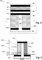
- FIG. 2 provides an example 203 for the thermoelectric device 103.
- the thermoelectric device 203 comprises p-leg 219, which comprises at least one p-doped semiconductor segment, and n-leg 220, which comprises at least one segment of a n-doped semiconductor region.
- the legs 219 and 220 span a gap between a hot junction 207 and a cold junction 208.
- Electrical insulation 222 isolates the legs.
- Metal interconnects 218 are provided adjacent or within the hot junction 207.
- Ohmic contacts are connect each of the legs 219 and 220 to the metal of interconnect 218, whereby the p-leg 219, the metal interconnect 218, and the n-leg 220 provide a p-i-n junction.
- the p-i-n junction creates electric fields through legs 219 and 220.
- the legs 219 and 220 have ohmic contacts with leads 221a and 221b. These leads are electrically isolated from one another although they may be part of a single metal interconnect layer, an interconnect layer being a pattern of metal in a planar matrix of dielectric.
- thermoelectric device 203 When the hot junction 207 is maintained at a higher temperature than the cold junction 208, charge carrier gradients form in the legs causing electrons to flow down the p-leg 219 and holes (effectively) down the n-leg 220.
- the potential difference between the leads varies depending on the temperature differential between the hot and cold junctions.
- the voltage is approximately proportional to the temperature difference.
- the electric current multiplied by the voltage gives the available power provided by the thermoelectric device 203.
- the ideal efficiency with which such a device converts thermal energy to electrical energy is given by well-known formulas that show dependencies on the temperature difference between the hot and cold junctions, the geometry, and the properties of the materials making up the p and n-legs.
- T H is the hot junction temperature
- T C is the cold junction temperature
- M 1 + ZT
- ZT a dimensionless material property known as the thermoelectric figure of merit.
- T is an average temperature.
- the first term in equation (1) is the Carnot efficiency.
- the Carnot efficiency is a consequence of entropy and cannot be avoided by any type of device for converting thermal energy to electrical energy.
- the second term in Equation (1) shows the separation between a thermoelectric device and an ideal device.
- the major dependence of this term is the dependence on ZT, with higher values being better. Until recently, the best values of ZT were about 1.0 and limited the efficiency of thermoelectric devices to about 20% of the Carnot efficiency.
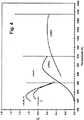
- Figure 4 shows the figures of merit of several semiconductor materials over a range of temperatures. It can be seen from this figure that different semi-conductor materials are effective over different temperature ranges. This complicated the selection of semiconductor materials, because the thermoelectric device 103 is intended to operate with the temperature gradient running through the legs 219 and 220: the temperature is expected to vary greatly over the lengths of the legs. High temperatures will occur at the tops legs 219 and 220 and low temperatures at the bottoms. A material that would provide a good figure of merit may give poor performance at the bottom and vice versa.
- Figure 3 illustrates the preferred solution and a preferred selection of materials.
- the solution is to make each of the legs 219 and 220 from a plurality of segments, each segment corresponding to a different semiconductor material.
- the lower segments 219c and 220c are selected to have high figures of merit at lower temperatures, and the upper segments 219a and 220a are selected to have high figures of merit at high temperatures.
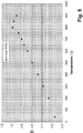
- FIG. 5 provides an exemplary result for comparison with Figure 4 .
- Quantum confinement is provided by nano-scale structures formed in the semiconductor matrix.
- the nanostructures are particles of p-SiGe crystal in of mixed sizes in the range from 1 -200 nm.
- Nano-scale structure include quantum wells, quantum wires, and quantum dots. Quantum dots provide the most benefit.
- These nano-scale structures are composite structures: the dots are small crystals of a second, suitably selected, semiconductor material formed in the matrix of another semiconductor. Suitable materials for the nanostructure can be found for each of the matrix materials. Some additional examples include Bi 0.3 Sb 1.7 Te 3 .
- One technique for forming the quantum dots is to alternate between depositing a few layers of the matrix materials and depositing a few layers comprising the matrix material together with wells of the second material. Details of suitable techniques are in the public domain. The materials and methods that have been described by workers at the Massachusetts Institute of Technology (MIT) are recommended. Those not familiar with these materials and methods can find them described in various publications including US 6 444 896 B1 and US 2006 0 118 158 A1 , US 2008 0 202 575 A1 , US 2009 0 068 465 A1 .
- Parameters that can be tuned in order to improve the result include thickness of the quantum well structures, their interspacing, and the atomic proportions of the alloys. Segmentation as shown in Figure 3 remains desirable for the nanocomposites, although it will be noted that the composites have their peak ZT values in temperature ranges shifted from those for the source materials. Adjusting the composition of the nanostructure alloy is one way to shift the temperatures at which high ZT values occur.
- One type of leg can be made wider than the other; width being meant in the sense of greater cross-sectional area.
- the other mode of adjustment is to place a pedestal under one or the other leg so that one leg can be shorter than the other.
- a pedestal is a leg segment made of a thermally conductive material such as a metal.
- the structure of the solar powered generator 100 determines the magnitude of the temperature gradients that will develop across the thermoelectric device 103.
- the main factors that determine that gradient are the solar concentration factor, f , and the thermal resistivity of the thermoelectric generator 103. That thermal resistivity can be tuned by adjusting the height of the legs 219 and 220.
- the solar concentration f together with the intensity of the sun's radiation determine the required heat flux.
- the entire sun's spectrum to the extent practical will be concentrated and focused on the surface of the solar panel 102. While some of the energy will be converted to electricity, the great majority, typically 90% to 95%, will become thermal energy.
- the configuration is for all the heat to go in one direction, downward, perpendicular to the surfaces of the solar panel 102.
- the thermoelectric device 103 is conformal with the solar panel 102.
- the energy flux density through the thermoelectric device 103 is nearly the same as that through the bottom surface of the solar panel 102.
- thermoelectric device 103 The maximum in the heat flux rate through the thermoelectric device 103 is given by the peak intensity of the sun's radiation on the Earth's surface, about 1.3 kW/m 2 multiplied by solar concentration factor, f . Corrections can be made for energy conversion to electricity by the solar panel 102 and parasitic (unintended) heat losses, but the result is still roughly the amount of heat flux per unit area that the thermoelectric device 103 must be designed to transport.
- ⁇ T is at least 200 °C, more preferably at least 300 °C.
- Higher values such as 500 °C and 600 °C can be desirable in that ⁇ T remains high even when the light level has dropped well below its peak.
- the main disadvantage of going to higher and higher temperature differentials is that peak temperatures are increased and materials begin to deteriorate and eventually fail.
- thermoelectric material requirement approximately f squared, 10,000 in this example.
- Solar concentration makes feasible the use of materials that would otherwise be too expensive. For this reason, low solar concentration is preferred over no solar concentration, moderate solar concentration is more preferred, and high solar concentration is still more preferred.
- Another advantage of solar concentration is that it facilitates reaching the target temperatures differential quickly; it has an effect similar to making the heat capacities less.
- legs 219 and 220 are themselves generally good insulators, even if they are just ordinary semiconductors. When they are made into nano-composites they become even better insulators: nano-structures improve the thermoelectric figure of merit by increasing the thermal resistivity more than the thermal conductivity of the composite material.
- substantially better insulators are air, vacuum, and aerogels.
- vacuum is encompassed within the term "insulating materials”.
- thermoelectric device 103 is conformal with the solar panel 102 in order that it drains heat uniformly from the back 106. This dictates the cross-sectional area for the device 103.
- the thermal resistivity offered by the thermoelectric device 103 is also constrained. If the thermal resistivity is too low, the desired temperature difference will not develop. If the thermal resistivity is too high, the solar panel 102 will heat excessively.
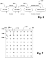
- thermoelectric device 10 A concept for reducing the amount of semiconductor material required for the thermoelectric device 10 and indeed for any thermoelectric device that is designed to provide a predetermined heat flux per unit area with a predetermined temperature gradient, is illustrated by Figure 7 , which corresponds to a cross-section of the thermoelectric device 203 through the plane of line A-A' of Figure 2 .
- a majority of the cross-sectional area (at least 50%), and volume, preferably at least 90%, is filled with a highly effective insulating material, preferably a material selected from the group consisting of vacuum, air, aerogel.
- a highly effective insulating material preferably a material selected from the group consisting of vacuum, air, aerogel. This reduces the area available for heat conduction through the legs 219 and 220 to a minority of the area (less than 50%), preferably less than 10%. If the cross-sectional area of the legs 219 and 220 is reduced by 50%, the thermal resistivity between the hot junction 207 and cold junction 208 is approximately doubled. To maintain the design temperature differential and heat flux the heights of the legs, h , are halved. The adjustment is applied to each segment if multiple segments are used.
- Halving the cross-sectional area and halving the height, h reduces the amount of material required by 75%. Reducing the cross-sectional area by 90% and reducing the height by 90% reduces the amount of required thermoelectric semiconductor material by a factor of 100. This is a particularly important advantage if expensive materials are used.
- the legs 219 and 220 are evenly and closely spaced through the matrix of insulation 222 throughout the entire area of the thermo-electric device 203. Close spacing can be maintained while reducing the fraction of the area occupied by the legs 219 and 220 by increasing the number of legs as their sizes are reduced. It should be appreciated that there are innumerable ways to meet these geometric constraints.
- the legs 219 and 220 can have cross-sections that are elongated like wires.
- a heat sink 104 can be anything that is functional to continuously draw heat from the cold junction 108 at such a rate that the solar powered generator 100 can arrive at steady state operation under continuous full sun.
- the heat sink 104 can comprise a fixed body of material, a body of water for example, or comprise a heat exchanger that transfers heat from the cold junction 108 to an essentially inexhaustible flow, as in the case of a heat exchanger with fins and a steady stream of air. While the solar generator 100 is not limited with respect to the type of heat sink 104, it has particular utility for a certain class of heat sink.
- One such class of heat sink is a partially closed system of such limited capacity to take up heat that under continuous full sun the heat sink 104 is warmed significantly by the solar powered generator 100.
- Significance in this context means a substantial change in the consequent temperatures within the solar generator 100. For example, a significant change would cause the cold junction 108 to become at least 40°C hotter, and a more significant change would cause the cold junction 108 to become at least 100 °C hotter. Such changes will affect steady state temperatures throughout the solar powered generator 100. Any change in the temperature of the heat sink 104 that causes the temperature of the solar panel 102 to rise by 40 °C or more is significant because of the reduction in efficiency that this would cause if ordinary solar panel materials were used. In this regard a change of 100 °C would be very significant.
- the solar powered generator 100 can provide a valuable improvement in comparison to a conventional solar thermal cogeneration system, which would lack the thermoelectric device 103 or a design that encourages heating more than a few degrees above the desired hot water temperature.
- the solar powered generator 100 is designed for the thermoelectric device 103 to be the predominant mode of electric power generation.
- the generator 100 remains highly functional in the face of temperature changes that would undermine the efficiency of a conventional solar panel.
- the solar power generator 100 is connected to a heat sink 104 that is by its nature limited in effectiveness or variable in its temperature, whereby the solar powered generator 100 will operate with the temperature of the cold junction 108 varying by 40 °C (Kelvin) or more, optionally 100 °C (Kelvin) or more.
- the method comprises developing a large temperature gradient across the thermoelectric device 103, whereby the thermoelectric device 103 is the predominant mode of electricity generation, producing more power than the solar panel 102.
- the large temperature gradient is brought about by exposing the solar panel 102 to sunlight light with a sufficiently high solar concentration factor, f.
- thermoelectric device 103 which is selected to allow the desired gradient to be generated with the solar concentration factor f that is provided by or achievable with the solar concentration system 101.
- the advantage of the method is that it provides power generation with an efficiency that has a low sensitivity to fluctuations in the heat sink performance and the cold junction temperature.
- a heat sink 104 having limited capacity could be a domestic hot water system, depending on the amount of water it contains in relation to the capacity of the generator 100. If the solar powered generator is merely a supplemental heating system whereby the hot water remains at an essentially constant temperature, the heat sink 104 will be efficient and an ordinary solar thermal generator would most likely better serve. On the other hand, if the hot water temperature varies between 50°C and 95°C, or 25 °C and 95°C, in the necessary course of its functioning as the heat sink, than it is a heat sink of limited capacity.
- heat sinks that may motivate the use of the solar generator 100 include those that vary widely in temperature of their own accord, either in terms of heat sink temperature or heat transfer coefficient.
- the heat sink 104 could be a cooling system of a vehicle. When the vehicle's engine is stopped the solar generator 100 can serve to keep the coolant, providing easy starts on cold days and reducing cold start emissions. Another potential use would be cabin heating while the engine is not running, and thereby avoiding the need to idle the engine. If enough cooling can be provided to prevent overheating, by running the engine fan of example, an air conditioner can be powered with the engine off.
- the solar generator 100 can provide auxiliary power and thus improve the vehicle's efficiency. If there is a danger of overheating, running an engine fan may be enough. These uses make do with a heat sink that is highly variable and can exceed 100 °C in temperature.
- the solar powered generator 100 will typically operate efficiently with a heat sink in the temperature range from 100 °C to 200 °C.
- a solar tracker would be a suitable means, if one is used.
- a tracking system can orient the collector away from the sun if that becomes desirable to prevent overheating. If the solar concentration system 101 provides a controllable solar concentration factor, f , that factor can be reduced. In general, however, it is preferred that the solar concentration system 101 provide as much light to the solar panel 102 as it is capable of providing.
- the heat sink 104 is a heat exchanger that transfers heat from the cold junction 108 to the ambient.
- a heat sink may have a highly variable performance that depends on ambient temperature and whether the vehicle is moving or stopped.
- the heat sink 104 may be inadequate to maintain a sufficiently constant temperature to maintain a conventional solar panel in an efficient mode of operation.
- the solar powered generator 100 can make do with much less cooling as compared to a similar device using just a solar panel.
- the solar powered generator 100 can be designed to operate efficiently over a broad range of heat sink temperatures. Designing for a high temperature gradient through the thermoelectric device 103 shifts power generation to the thermoelectric device 103 and reduces reliance on the solar panel 102.
- the effective functioning of the solar panel 102 can be limited to warm-up periods during which the thermoelectric device 103 has not developed the temperature gradient it requires to operate efficiently.
- the solar powered generator 100 could be used to drive a vehicle or as part of a hybrid drive system. In such a system, it is advantageous to have electric power as soon as the sun comes out.
- thermoelectric generator 103 produces its current at a voltage that varies with the temperature difference between hot junction 107 and the cold junction 108.
- the solar powered generator 100 receives varying amounts of light over the course of any given day, whereby the heat flux, temperature gradient and resulting voltage will necessarily vary substantially. Therefore, it is preferred that the solar powered generator 100 be provided with an electrical system including a voltage regulator for drawing the current from the thermoelectric device 103 at the voltage it is supplied and outputting that current at a constant voltage.
- the solar panel 102 provides power separately from the thermoelectric generator 103. It will generally be desired to combine the output from the solar panel 102 with that of the solar generator 103 in order to form a single source. This is accomplished by providing the solar powered generator 100 with electrical components for combining and matching the voltages from these two sources.
- the solar powered generator 100 includes an electrical energy storage system.
- This energy storage system may comprise batteries and or capacitors.
- Another option that may be useful is a standard coupling for plugging in to the solar powered generator 100.
- a transformer may also be included to convert the direct current into an alternating current with a standard frequency and voltage.
- the solar concentration system 101 concentrates sunlight 109 onto the surface 105 of the solar panel 102.
- the solar panel 102 absorbs most of this sunlight (radiation) and from it produces electrical energy with an efficiency that diminishes with increasing temperature. Most of the absorbed radiation is converted to thermal energy.
- thermoelectric device 103 comprises hot junction 107 and cold junction 108.
- the hot junction 107 is proximate to and in close thermal contact with the bottom surface 106 of the solar panel 102.
- thermoelectric device 103 provides the primary pathway for which the solar panel 102 gives up its heat. If necessary, the solar panel 102 can be contained within an enclosed and/or insulated space to reduce other pathways of heat loss. By eliminating or reducing other pathways of heat dissipation, the vast majority of the thermal energy absorbed by the solar panel 102 can be directed through the thermoelectric device 103, whereby it can be used for electrical power production.
- Reflectors may be positioned to redirect this emitted and reflected light to re-reflect the light back upon the surface 105. These reflectors may comprise a mirror chamber substantially a space over the surface 105. Such reflectors can provide a significant increase in efficiency.
- thermoelectric device 103 Heat from the hot junction 107 flows to the cold junction 108. A portion of the thermal energy transported in this way is converted to electricity by the thermoelectric device 103.
- the solar powered generator 100 generates electricity in at least two places. The electrical power from these sources can be transformed and combined in order to provide a unitary power supply at a constant voltage using electronic parts separate from or integrated into the solar powered generator 100.
- Heat sink 104 draws heat away from the cold junction 108.
- the heat sink 104 may be highly efficient and maintain the cold junction 108 at an essentially constant temperature regardless of the intensity of the sunlight 109.
- the heat sink 104 may be inefficient whereby the temperature of the cold junction 108 varies.
- the temperature of the hot junction 107 varies correspondingly, as the temperature differential is determined by the heat flux rate, which is substantially independent of the cold junction temperature.
- the hot junction temperature rise to match.
- the hot junction temperature rises until the heat input to the solar cell 102 matches the heat output to the hot junction 108. This matching occurs at approximately the same temperature differential regardless of the cold junction temperature.
- an increase in the cold junction temperature soon leads to approximately equal increases in the temperatures of the hot junction 107 and the solar panel 102.
- the performance of solar powered generator 100 is illustrated by the finite state machine diagram 239 of Figure 6 .
- the generator 100 begins in the inactive state 240.
- the inactive state 240 all of the components of the solar powered generator 100 are near ambient temperature.
- the inactive state 240 is typical for nighttime.
- the main event that causes a departure from the inactive state 240 is the sun rising. This event moves the device 100 to the low-temperature operating state 241. In the low-temperature operating state 241, the solar panel 102 is producing power near its peak efficiency, while the thermoelectric device 103 provides little or no power.
- the efficiency of the solar panel 102 decreases while power production by the thermoelectric device 103 increases.
- efficiency losses to the solar panel 102 are balanced by efficiency gains by the thermoelectric device 103, and visa-a-versa, whereby efficiency remains in a narrow range even as light and power levels fluctuate.
- the efficiency of the solar panel 102 drops during this period to a range in which power production by the solar panel 102 is very low in comparison to power production by the thermoelectric device 103, and the overall efficiency is substantially that of the thermoelectric device 103, which by and large increases monotonically with temperature.
- the temperature of the solar panel 102 is about its designed maximum, although the temperature of the solar panel 102 also depends on that of the heat sink 104, which can vary.
- the temperature gradient through the thermoelectric device 103 is also at approximately the designed maximum, depending on such factors as the season and time of day.
- Light input is near its maximum and efficiency of the thermoelectric device 103 is near its peak.
- the efficiency of the solar panel 102 is diminished to a degree that is either moderate or very great, depending on whether the solar panel 102 is adapted for high temperature operation. Even with the solar panel 102 adapted for high temperature operation, it would is typical for the thermoelectric device 103 to produce 2, 3, or 4 times as much power as the solar panel 102.
- Efficiency as well as power production in the solar powered generator 100 are typically highest in the high temperature steady state 243. Materials considerations are likely to be the factor militating against designing for even higher temperatures and temperature gradients and thereby accessing higher levels of efficiency.
- a rapid transition to the high temperature steady state 243 when full sun becomes available will generally provide greater efficiency. This transition is slowed according to the thermal mass of the solar panel 102 and any materials used to make contact between the solar panel 102 and the thermoelectric device 103. Where the panel 102 and the thermoelectric device 103 are manufactured separately, solder or thermal paste may be used to ensure a good contact. A small air gap at the interface could cause the temperature of the solar panel 102 to rise significantly above that of the hot junction 107, which would reduce the performance of the solar panel 102 without providing any benefit to the thermoelectric device 103. A more severe breakdown in contact could quickly result in a damaging temperature excursion, particularly if solar concentration factors. Such a breakdown could be caused by a deformation of one of the contact surfaces, which might itself be the result of temperature cycling.
- thermoelectric device 203 having a unitary construction.
- the solar panel 202 and the thermoelectric device 203 are layers in a composite structure similar to an integrated circuit.
- the layers are formed one over the other through a sequence of process steps. Processes of masking, etching, and deposition may be combined in various ways to produce the desired result. Most of the steps are, or can be, the same as those normally used to form the devices 102 and 103 individually, particularly with regard to the case where the solar panel 102 is a thin film solar cell and the thermoelectric device 103 comprises nano-composite segments formed through many separate layer deposition steps.
- the process of making the integrated device 200 may begin from the bottom up or the top down. Starting from a point where the thermoelectric device 203 is formed, the principle modification is to ensure the interconnect layer 207 is planar and to deposit a semiconductor substrate layer over the interconnect layer in such a way that the substrate does not easily delaminate.
- One approach is to deposit a metal layer over the interconnect layer 207. Forming a GaP solar cell over such a metal layer is a conventional process.
- the solar cell can be formed first.
- a temporary substrate Ge for example, as a structure on which to build the solar cell. All or just the bottom layers of the solar cell 202 are formed on the Ge substrate. Then the layers comprising the thermoelectric device 203 are built. Finally, the temporary substrate is removed, and if necessary, the solar cell 202 given additional processing to become completed.
- the integral construction provides a variety of advantages, including higher thermoelectric efficiency due to less thermal mass, excellent thermal contact between the solar panel 203 and the hot junction 207, and a better ability to with stand thermal cycling through a reduction in the number of layers, and the avoidance of thick layers.
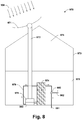
- the system 900 is a combined system for domestic solar hot water heating with cogeneration of electricity.
- the system 970 includes the solar collector 971, which is designed for rooftop installation.
- the collector 971 gathers solar energy 109 and transmits it via the fiber optic cable 972 to the solar powered generator 900.
- the size of the collector 971 is chosen in relation to the amount energy that an ordinary household will use for hot water heating. A size in the range from about 1 to 10 square meters could be suitable, typically in the range from about 2 to about 6 square meter.
- the solar powered generator 900 is located inside a building 973, preferably next to the water tank 974.
- Water tanks are usually in a basement 975 and it is preferable to avoid the energy waste of circulating hot water through long pipes.
- An location in attic 976 may be preferable for ease of installation.
- a suitable size for the tank 974 would be in the range from 100 to 1000 liters, more typically in the range from about 200 to about 600 liters.
- the fiber optic bundle 972 shines light onto the surface of the solar panel of the solar powered generator 900, preferably with a high degree of solar concentration.
- An intensity in the range from 50 to 250 suns would be preferred.
- the solar panel At 100 suns, the solar panel would be in the range from 100 to 1000 cm 2 .
- a mirror chamber comprising mirrors on the inside and surrounded by vacuum insulated double-pane glass, traps heat and light rising off the solar panel.
- the solar panel develops its maximum designed temperature gradient, which is 77 °C (350 Kelvin).
- the heat from the solar panel is transmitted by a thermal-electric generator to the heat exchanger 978.
- the heat exchanger 978 forms part of a loop 979 through which water re-circulates between the tank 974 and the heat exchanger 978.
- the solar powered generator 900 By placing the solar powered generator 900 near the base of the tank the re- circulating flow can be powered thermo-gravimetrically. Alternatively, an electric pump could be used.
- the hot water system comprising the heat exchanger 978, the loop 979 and the tank 974 provide the heat sink that is a closed system with a limited capacity to absorb heat. Fluctuations in user demand are accommodated in part by allowing the water temperature to vary through a wide range.
- a back-up gas heater may bottom the generator 900 to provide a minimum temperature of 50 °C. The water can then be allowed to heat to 95 °C before taking any measures to release the excess heat.
- a mixing valve 980 is configured to automatically adjust a mixing ratio between water from the tank 974 and a cold water supply 981 to provide water on demand at a preset temperature. If the hot water temperature reaches its allowed maximum, heat can be surrendered by dumping hot water or defocusing the solar collector 971. As the heat sink cycles from 50 °C to 95 °C, the solar panel is expected to cycle from 400 °C to 445 °C. This cycling is not expected to affect electrical power production.
- thermoelectric device efficiency is expected to reach about 9% at steady state, giving a total efficiency of 16%. If nano-composite materials are used to provide 2.0 ZT, the efficiency of the thermoelectric device alone is 16% and the total efficiency is 25%. If the solar panel temperature drops 100 °C, the overall efficiency only drops to 23%. Power would drop more because the temperature drop is caused by diminished light.
- the efficiency drops off more rapidly at lower temperatures, but remains high over a substantial range of light levels and water tank temperatures.
- the high temperature differential design, the adaptation of the solar panel to high temperature performance and the efficient use of semiconductors that enable the use of high ZT materials combine to provide a system that is economical and efficient.
- the present invention is useful for green energy production.
Landscapes
- Photovoltaic Devices (AREA)
Applications Claiming Priority (2)
| Application Number | Priority Date | Filing Date | Title |
|---|---|---|---|
| US19825608P | 2008-11-04 | 2008-11-04 | |
| PCT/US2009/063288 WO2010053997A1 (en) | 2008-11-04 | 2009-11-04 | Combined solar/thermal (chp) heat and power for residential and industrial buildings |
Publications (3)
| Publication Number | Publication Date |
|---|---|
| EP2345087A1 EP2345087A1 (en) | 2011-07-20 |
| EP2345087A4 EP2345087A4 (en) | 2017-06-14 |
| EP2345087B1 true EP2345087B1 (en) | 2019-08-21 |
Family
ID=42153221
Family Applications (1)
| Application Number | Title | Priority Date | Filing Date |
|---|---|---|---|
| EP09825364.4A Not-in-force EP2345087B1 (en) | 2008-11-04 | 2009-11-04 | Combined solar/thermal (chp) heat and power for residential and industrial buildings |
Country Status (9)
| Country | Link |
|---|---|
| US (1) | US8921683B2 (enExample) |
| EP (1) | EP2345087B1 (enExample) |
| JP (1) | JP5984391B2 (enExample) |
| CN (1) | CN102272940B (enExample) |
| BR (1) | BRPI0916044B1 (enExample) |
| MX (1) | MX2011004783A (enExample) |
| RU (1) | RU2513649C2 (enExample) |
| WO (1) | WO2010053997A1 (enExample) |
| ZA (1) | ZA201103749B (enExample) |
Families Citing this family (60)
| Publication number | Priority date | Publication date | Assignee | Title |
|---|---|---|---|---|
| FR2939968B1 (fr) * | 2008-12-17 | 2013-06-07 | Eads Europ Aeronautic Defence | Generateur electrique excite par rayonnements cosmiques. |
| NO333520B1 (no) * | 2009-11-06 | 2013-07-01 | Flaax Holding As | Solcelletaksten |
| US20110290295A1 (en) * | 2010-05-28 | 2011-12-01 | Guardian Industries Corp. | Thermoelectric/solar cell hybrid coupled via vacuum insulated glazing unit, and method of making the same |
| US8492788B2 (en) * | 2010-10-08 | 2013-07-23 | Guardian Industries Corp. | Insulating glass (IG) or vacuum insulating glass (VIG) unit including light source, and/or methods of making the same |
| US8569861B2 (en) * | 2010-12-22 | 2013-10-29 | Analog Devices, Inc. | Vertically integrated systems |
| US20120192920A1 (en) * | 2011-01-27 | 2012-08-02 | Total Energy Renewable Power Systems, Llc | Stacked Layer High Efficiency Solar Energy Collector |
| CN102208470A (zh) * | 2011-05-03 | 2011-10-05 | 大连皿能光电科技有限公司 | 热电联产bipv组件 |
| EP2528124A1 (en) * | 2011-05-23 | 2012-11-28 | Holdingselskabet TEG af 2011 ApS | A power generator |
| ITMI20111643A1 (it) * | 2011-09-13 | 2013-03-14 | Franco Baldi | Generatore lenticolare di corrente elettrica a concentrazione di fotoni con reazione termica ibrido e compatto a differenti focalizzazioni della luce visibile e invisibile |
| JP6370532B2 (ja) * | 2012-05-11 | 2018-08-08 | 公立大学法人大阪府立大学 | 光熱変換素子およびその製造方法、光熱発電装置ならびに被検出物質の検出方法 |
| US8829331B2 (en) | 2012-08-10 | 2014-09-09 | Dimerond Technologies Llc | Apparatus pertaining to the co-generation conversion of light into electricity |
| US9040395B2 (en) | 2012-08-10 | 2015-05-26 | Dimerond Technologies, Llc | Apparatus pertaining to solar cells having nanowire titanium oxide cores and graphene exteriors and the co-generation conversion of light into electricity using such solar cells |
| US10910962B2 (en) | 2012-10-19 | 2021-02-02 | University Of Southern California | Pervasive power generation system |
| US9960336B2 (en) | 2013-01-08 | 2018-05-01 | Analog Devices, Inc. | Wafer scale thermoelectric energy harvester having trenches for capture of eutectic material |
| US9748466B2 (en) | 2013-01-08 | 2017-08-29 | Analog Devices, Inc. | Wafer scale thermoelectric energy harvester |
| US9620700B2 (en) * | 2013-01-08 | 2017-04-11 | Analog Devices, Inc. | Wafer scale thermoelectric energy harvester |
| US10224474B2 (en) | 2013-01-08 | 2019-03-05 | Analog Devices, Inc. | Wafer scale thermoelectric energy harvester having interleaved, opposing thermoelectric legs and manufacturing techniques therefor |
| US9620698B2 (en) | 2013-01-08 | 2017-04-11 | Analog Devices, Inc. | Wafer scale thermoelectric energy harvester |
| CN105324850B (zh) * | 2013-06-24 | 2017-04-19 | 三菱电机株式会社 | 太阳光发电装置用基板的制造方法及太阳光发电装置用基板的制造装置 |
| CN105940512A (zh) * | 2013-09-17 | 2016-09-14 | 罗杰·韦伯 | 用于附接到太阳能面板的模块化单元 |
| WO2015099567A1 (en) * | 2013-12-26 | 2015-07-02 | Limited Liability Company "Sms Tenzotherm Rus" | Photoelectric converter |
| CN104229120B (zh) * | 2014-09-22 | 2016-09-07 | 北京航空航天大学 | 一种基于光热一体化复合能源的太阳能飞机机翼结构 |
| JP6255553B2 (ja) * | 2014-10-07 | 2018-01-10 | 株式会社アクトリー | 太陽光発電システム |
| CN105720186B (zh) * | 2014-11-30 | 2019-01-08 | 中国科学院金属研究所 | 一种碳纳米纤维/铜复合材料及其作为热电池能量转换器件的应用 |
| US9871373B2 (en) | 2015-03-27 | 2018-01-16 | Analog Devices Global | Electrical overstress recording and/or harvesting |
| US10557881B2 (en) | 2015-03-27 | 2020-02-11 | Analog Devices Global | Electrical overstress reporting |
| KR101619388B1 (ko) * | 2015-06-09 | 2016-05-10 | 경희대학교 산학협력단 | 광범위한 복사 스펙트럼의 활용을 위한 하이브리드 열광전 에너지 변환 시스템 |
| US10672968B2 (en) | 2015-07-21 | 2020-06-02 | Analog Devices Global | Thermoelectric devices |
| CN106533328B (zh) * | 2015-09-11 | 2018-05-25 | 博立码杰通讯(深圳)有限公司 | 集成式太阳能利用装置及系统 |
| CA3003599A1 (en) * | 2015-11-03 | 2017-05-11 | Enerdynamic Hybrid Technologies Corp. | Systems for solar power generation and methods of constructing the same |
| US10135110B2 (en) * | 2015-12-14 | 2018-11-20 | Ford Global Technologies, Llc | Vehicle antenna assembly with cooling |
| RU2622495C1 (ru) * | 2016-03-25 | 2017-06-15 | Федеральное государственное бюджетное образовательное учреждение высшего образования "Юго-Западный государственный университет" (ЮЗГУ) | Походная гелиотермоэлектростанция |
| US10338132B2 (en) | 2016-04-19 | 2019-07-02 | Analog Devices Global | Wear-out monitor device |
| US10365322B2 (en) | 2016-04-19 | 2019-07-30 | Analog Devices Global | Wear-out monitor device |
| CN106252447B (zh) * | 2016-09-23 | 2019-03-05 | 华中科技大学 | 一种复合太阳能电池及其制备方法 |
| JP6820556B2 (ja) * | 2017-03-13 | 2021-01-27 | 国立研究開発法人産業技術総合研究所 | セグメント型熱電発電モジュール |
| CN110678745B (zh) | 2017-05-15 | 2023-03-10 | 亚德诺半导体国际无限责任公司 | 集成离子传感设备和方法 |
| US11024525B2 (en) | 2017-06-12 | 2021-06-01 | Analog Devices International Unlimited Company | Diffusion temperature shock monitor |
| JPWO2018230031A1 (ja) * | 2017-06-16 | 2019-06-27 | 三菱電機株式会社 | 太陽光発電パネル及びその製造方法 |
| US10730743B2 (en) | 2017-11-06 | 2020-08-04 | Analog Devices Global Unlimited Company | Gas sensor packages |
| WO2019118322A1 (en) * | 2017-12-11 | 2019-06-20 | University Of Kansas | Active daytime radiative cooling for air conditioning and refrigeration systems |
| US20190226441A1 (en) * | 2018-01-24 | 2019-07-25 | MTU Onsite Energy Corporation | Generator set startup using renewable energy |
| US12181351B2 (en) | 2018-02-28 | 2024-12-31 | Arthur Beckman | Thermopile assembly providing a massive electrical series of wire thermocouple elements |
| US11374533B2 (en) | 2018-05-31 | 2022-06-28 | Mitsubishi Electric Corporation | Solar power generation paddle, method of manufacturing the same, and space structure |
| JP6528924B1 (ja) * | 2018-05-31 | 2019-06-12 | 三菱電機株式会社 | 太陽光発電パドル、その製造方法及び宇宙構造物 |
| US12009451B2 (en) | 2018-07-30 | 2024-06-11 | mPower Technology, Inc. | In-situ rapid annealing and operation of solar cells for extreme environment applications |
| JP7503311B2 (ja) * | 2018-12-19 | 2024-06-20 | 国立研究開発法人産業技術総合研究所 | 太陽電池および熱電変換素子を有する複合発電装置 |
| US11043624B2 (en) | 2019-04-23 | 2021-06-22 | Imam Abdulrahman Bin Faisal University | System, device, and method for generating energy using a thermoelectric generator |
| CN120358826A (zh) | 2019-06-03 | 2025-07-22 | 蒂梅尔罗德科技有限责任公司 | 高效率石墨烯/宽带隙半导体异质结太阳能电池 |
| US11587839B2 (en) | 2019-06-27 | 2023-02-21 | Analog Devices, Inc. | Device with chemical reaction chamber |
| RU2715356C1 (ru) * | 2019-07-08 | 2020-02-26 | Федеральное государственное бюджетное образовательное учреждение высшего образования "Юго-Западный государственный университет" (ЮЗГУ) | Универсальная гелиотермоэлектростанция |
| EP4052305A4 (en) * | 2019-10-30 | 2023-11-15 | mPower Technology, Inc. | RAPID IN-SITU ANNEALING AND OPERATION OF SOLAR CELLS FOR APPLICATIONS IN EXTREME ENVIRONMENTS |
| US12474290B2 (en) | 2019-11-20 | 2025-11-18 | Analog Devices International Unlimited Company | Electrochemical device |
| CN112768593B (zh) * | 2021-01-06 | 2022-06-28 | 南方科技大学 | 一种热电-光电器件 |
| US20220285571A1 (en) * | 2021-03-08 | 2022-09-08 | The Johns Hopkins University | Nano-engineered thin-film thermoelectric converter for photovoltaic applications |
| US11777441B2 (en) | 2021-04-01 | 2023-10-03 | Hamilton Sundstrand Corporation | Thermoelectric power generation using radiant and conductive heat dissipation |
| CN113838944B (zh) * | 2021-08-27 | 2024-06-21 | 中国华能集团清洁能源技术研究院有限公司 | 集成式热光伏电池 |
| US12389713B1 (en) | 2022-04-12 | 2025-08-12 | Tilahun Anshu | Solar panel |
| KR102729440B1 (ko) * | 2022-11-08 | 2024-11-13 | 재단법인 구미전자정보기술원 | 태양전지 및 태양광 모듈을 재활용하는 방법 및 장치 |
| IT202300019371A1 (it) * | 2023-09-20 | 2025-03-20 | I2T Sa | Apparato per la conversione di radiazione elettromagnetica in corrente elettrica e calore |
Family Cites Families (49)
| Publication number | Priority date | Publication date | Assignee | Title |
|---|---|---|---|---|
| US2984696A (en) * | 1959-03-09 | 1961-05-16 | American Mach & Foundry | Solar thermoelectric generators |
| JPS50134391A (enExample) * | 1974-04-09 | 1975-10-24 | ||
| US4002031A (en) * | 1975-07-07 | 1977-01-11 | Varian Associates, Inc. | Solar energy converter with waste heat engine |
| US4106952A (en) * | 1977-09-09 | 1978-08-15 | Kravitz Jerome H | Solar panel unit |
| US4235221A (en) * | 1979-08-23 | 1980-11-25 | Murphy Gerald G | Solar energy system and apparatus |
| US4350144A (en) * | 1980-08-18 | 1982-09-21 | Stanford Associates, Inc. | Hot water heating system |
| JPS58213479A (ja) * | 1982-06-04 | 1983-12-12 | Futaba Corp | エネルギ−変換素子 |
| US4640977A (en) * | 1984-04-23 | 1987-02-03 | Omnimax Energy Corporation | Thermoelectric generator using variable geometry with support pedestals of dissimilar materials than the basic thermoelectric semi-conductor elements |
| US4710588A (en) * | 1986-10-06 | 1987-12-01 | Hughes Aircraft Company | Combined photovoltaic-thermoelectric solar cell and solar cell array |
| JPH01105582A (ja) * | 1987-10-19 | 1989-04-24 | Kuretsuku Syst:Kk | 太陽光発電素子 |
| US5269851A (en) * | 1991-02-25 | 1993-12-14 | United Solar Technologies, Inc. | Solar energy system |
| US5518554A (en) * | 1994-01-27 | 1996-05-21 | Newman; Edwin | Cascade process heat conversion system |
| US5851310A (en) * | 1995-12-06 | 1998-12-22 | University Of Houston | Strained quantum well photovoltaic energy converter |
| US6147296A (en) * | 1995-12-06 | 2000-11-14 | University Of Houston | Multi-quantum well tandem solar cell |
| JPH10150215A (ja) * | 1996-11-15 | 1998-06-02 | Yamaura:Kk | 太陽光を利用した発電装置 |
| US5936193A (en) * | 1997-05-09 | 1999-08-10 | Parise; Ronald J. | Nighttime solar cell |
| CA2367686C (en) * | 1999-03-11 | 2011-07-12 | Yan Kucherov | Hybrid thermionic energy converter and method |
| US6444896B1 (en) * | 1999-08-27 | 2002-09-03 | Massachusetts Institute Of Technology | Quantum dot thermoelectric materials and devices |
| US6548751B2 (en) * | 2000-12-12 | 2003-04-15 | Solarflex Technologies, Inc. | Thin film flexible solar cell |
| DE10139509A1 (de) * | 2000-12-08 | 2002-06-27 | Daimler Chrysler Ag | Silizium Germanium Solarzelle mit hohem Wirkungsgrad |
| US6673996B2 (en) * | 2001-01-17 | 2004-01-06 | California Institute Of Technology | Thermoelectric unicouple used for power generation |
| US7273981B2 (en) * | 2001-02-09 | 2007-09-25 | Bsst, Llc. | Thermoelectric power generation systems |
| US6895145B2 (en) * | 2001-08-02 | 2005-05-17 | Edward Ho | Apparatus and method for collecting light |
| JP2003069065A (ja) * | 2001-08-29 | 2003-03-07 | Canon Inc | 太陽光発電システム |
| US7973235B2 (en) * | 2001-09-18 | 2011-07-05 | Ut-Batelle, Llc | Hybrid solar lighting distribution systems and components |
| JP2003113771A (ja) * | 2001-10-04 | 2003-04-18 | Kawasaki Heavy Ind Ltd | 太陽エネルギーを利用した発電装置 |
| US7800194B2 (en) * | 2002-04-23 | 2010-09-21 | Freedman Philip D | Thin film photodetector, method and system |
| CA2388195A1 (en) * | 2002-05-28 | 2003-11-28 | Alberta Research Council Inc. | Hybrid solar energy collector |
| WO2003105240A1 (en) * | 2002-05-30 | 2003-12-18 | Rensselaer Polytechnic Institute | Composite thermal system |
| JP2004056866A (ja) * | 2002-07-17 | 2004-02-19 | Nec Engineering Ltd | 発電機能を備えた携帯通信機器 |
| US7578102B2 (en) * | 2002-08-16 | 2009-08-25 | Mark Banister | Electric tile modules |
| US7148417B1 (en) * | 2003-03-31 | 2006-12-12 | The United States Of America As Represented By The Administrator Of The National Aeronautics And Space Administration | GaP/silicon tandem solar cell with extended temperature range |
| JP2006086313A (ja) * | 2004-09-16 | 2006-03-30 | Yoshiharu Fujii | 太陽電池発電システム |
| US7465871B2 (en) | 2004-10-29 | 2008-12-16 | Massachusetts Institute Of Technology | Nanocomposites with high thermoelectric figures of merit |
| US8865995B2 (en) * | 2004-10-29 | 2014-10-21 | Trustees Of Boston College | Methods for high figure-of-merit in nanostructured thermoelectric materials |
| US7309830B2 (en) | 2005-05-03 | 2007-12-18 | Toyota Motor Engineering & Manufacturing North America, Inc. | Nanostructured bulk thermoelectric material |
| US20060225782A1 (en) * | 2005-03-21 | 2006-10-12 | Howard Berke | Photovoltaic cells having a thermoelectric material |
| WO2006113607A2 (en) * | 2005-04-18 | 2006-10-26 | Nextreme Thermal Solutions | Thermoelectric generators for solar conversion and related systems and methods |
| JP2007081097A (ja) * | 2005-09-14 | 2007-03-29 | Frontier Material:Kk | 太陽光・熱ハイブリッドモジュールおよびハイブリッド発電システム、並びに建材一体型モジュールおよび建物 |
| JP4868820B2 (ja) * | 2005-10-20 | 2012-02-01 | シャープ株式会社 | 化合物太陽電池及び製造方法 |
| JP2007166721A (ja) * | 2005-12-12 | 2007-06-28 | Hikita Kogyo Kk | 発電装置 |
| WO2007087343A2 (en) * | 2006-01-25 | 2007-08-02 | Intematix Corporation | Solar modules with tracking and concentrating features |
| US20070277866A1 (en) * | 2006-05-31 | 2007-12-06 | General Electric Company | Thermoelectric nanotube arrays |
| ATE468615T1 (de) * | 2006-07-24 | 2010-06-15 | Fiat Ricerche | Vorrichtung zur wandlung von elektromagnetischer strahlung in elektrische energie und korrespondierende wandlungsverfahren |
| JP2008047666A (ja) * | 2006-08-14 | 2008-02-28 | Toyota Motor Corp | エネルギー管理システム |
| US20080128021A1 (en) * | 2006-09-06 | 2008-06-05 | The Research Foundation Of State University Of New York | Nanocomposite devices, methods of making them, and uses thereof |
| US8044292B2 (en) * | 2006-10-13 | 2011-10-25 | Toyota Motor Engineering & Manufacturing North America, Inc. | Homogeneous thermoelectric nanocomposite using core-shell nanoparticles |
| JP2008108900A (ja) * | 2006-10-25 | 2008-05-08 | Toshiba Corp | 熱電変換モジュールおよび熱電変換装置 |
| JP4850083B2 (ja) * | 2007-02-01 | 2012-01-11 | 京セラ株式会社 | 熱電変換モジュール及びそれを用いた発電装置及び冷却装置 |
-
2009
- 2009-11-04 EP EP09825364.4A patent/EP2345087B1/en not_active Not-in-force
- 2009-11-04 JP JP2011535645A patent/JP5984391B2/ja active Active
- 2009-11-04 RU RU2011122626/28A patent/RU2513649C2/ru active
- 2009-11-04 MX MX2011004783A patent/MX2011004783A/es active IP Right Grant
- 2009-11-04 WO PCT/US2009/063288 patent/WO2010053997A1/en not_active Ceased
- 2009-11-04 CN CN200980153483.6A patent/CN102272940B/zh active Active
- 2009-11-04 US US13/127,415 patent/US8921683B2/en active Active
- 2009-11-04 BR BRPI0916044-2A patent/BRPI0916044B1/pt active IP Right Grant
-
2011
- 2011-05-20 ZA ZA2011/03749A patent/ZA201103749B/en unknown
Non-Patent Citations (1)
| Title |
|---|
| None * |
Also Published As
| Publication number | Publication date |
|---|---|
| RU2011122626A (ru) | 2012-12-20 |
| EP2345087A4 (en) | 2017-06-14 |
| ZA201103749B (en) | 2012-08-29 |
| BRPI0916044B1 (pt) | 2019-06-18 |
| JP2012508466A (ja) | 2012-04-05 |
| WO2010053997A1 (en) | 2010-05-14 |
| EP2345087A1 (en) | 2011-07-20 |
| CN102272940B (zh) | 2015-09-23 |
| RU2513649C2 (ru) | 2014-04-20 |
| MX2011004783A (es) | 2011-07-29 |
| JP5984391B2 (ja) | 2016-09-06 |
| US20110209744A1 (en) | 2011-09-01 |
| BRPI0916044A2 (pt) | 2015-11-10 |
| CN102272940A (zh) | 2011-12-07 |
| US8921683B2 (en) | 2014-12-30 |
Similar Documents
| Publication | Publication Date | Title |
|---|---|---|
| EP2345087B1 (en) | Combined solar/thermal (chp) heat and power for residential and industrial buildings | |
| Parthiban et al. | An enhancement of the solar panel efficiency: a comprehensive review | |
| Huen et al. | Advances in hybrid solar photovoltaic and thermoelectric generators | |
| Yang et al. | Energy conversion efficiency of a novel hybrid solar system for photovoltaic, thermoelectric, and heat utilization | |
| Cui et al. | Experimental investigation on potential of a concentrated photovoltaic-thermoelectric system with phase change materials | |
| Radziemska | Thermal performance of Si and GaAs based solar cells and modules: a review | |
| Makki et al. | Numerical investigation of heat pipe-based photovoltaic–thermoelectric generator (HP-PV/TEG) hybrid system | |
| US5936193A (en) | Nighttime solar cell | |
| US20110139203A1 (en) | Heterostructure thermoelectric generator | |
| Li et al. | Conversion efficiency gain for concentrated triple-junction solar cell system through thermal management | |
| CN103426963A (zh) | 聚集光伏/量子阱热电功率源 | |
| Gopinath et al. | PV-TEG output: Comparison with heat sink and graphite sheet as heat dissipators | |
| WO2008132445A2 (en) | Solar cell | |
| Yin et al. | Unsteady-state performance comparison of tandem photovoltaic-thermoelectric hybrid system and conventional photovoltaic system | |
| Zhou et al. | Multi-scale multi-physic coupled investigation on the matching and trade-off of conversion and storage of optical, thermal, electrical, and chemical energy in a hybrid system based on a novel full solar spectrum utilization strategy | |
| Khvostikov et al. | Photovoltaic cells based on GaSb and Ge for solar and thermophotovoltaic applications | |
| US8283553B1 (en) | Photon enhanced thermoelectric power generation | |
| CN201726340U (zh) | 一种太阳能光电、热电转换系统 | |
| CN114826024A (zh) | 一种无需储存的24小时光伏-热电耦合发电系统 | |
| CN120016955A (zh) | 一种高效利用太阳光的光伏-光热-热电的耦合系统 | |
| JP6255553B2 (ja) | 太陽光発電システム | |
| CN207117533U (zh) | 一种照明发电系统 | |
| Ramasesha | Challenges in the Quest for Clean Energies: 2. Solar Energy Technologies | |
| Pawar et al. | Photovoltaic Thermoelectric Solar Generation Technique | |
| Balkan et al. | Solar Cells (Photovoltaic Cells) |
Legal Events
| Date | Code | Title | Description |
|---|---|---|---|
| PUAI | Public reference made under article 153(3) epc to a published international application that has entered the european phase |
Free format text: ORIGINAL CODE: 0009012 |
|
| 17P | Request for examination filed |
Effective date: 20110504 |
|
| AK | Designated contracting states |
Kind code of ref document: A1 Designated state(s): AT BE BG CH CY CZ DE DK EE ES FI FR GB GR HR HU IE IS IT LI LT LU LV MC MK MT NL NO PL PT RO SE SI SK SM TR |
|
| AX | Request for extension of the european patent |
Extension state: AL BA RS |
|
| DAX | Request for extension of the european patent (deleted) | ||
| RIC1 | Information provided on ipc code assigned before grant |
Ipc: H02S 10/10 20140101ALI20170130BHEP Ipc: H01L 35/22 20060101ALI20170130BHEP Ipc: H01L 35/30 20060101ALI20170130BHEP Ipc: H01L 35/26 20060101ALI20170130BHEP Ipc: H01L 31/042 20140101AFI20170130BHEP |
|
| RA4 | Supplementary search report drawn up and despatched (corrected) |
Effective date: 20170515 |
|
| RIC1 | Information provided on ipc code assigned before grant |
Ipc: H01L 35/22 20060101ALI20170509BHEP Ipc: H01L 31/042 20140101AFI20170509BHEP Ipc: H01L 35/30 20060101ALI20170509BHEP Ipc: H01L 35/26 20060101ALI20170509BHEP Ipc: H02S 10/10 20140101ALI20170509BHEP |
|
| STAA | Information on the status of an ep patent application or granted ep patent |
Free format text: STATUS: EXAMINATION IS IN PROGRESS |
|
| 17Q | First examination report despatched |
Effective date: 20181015 |
|
| RIC1 | Information provided on ipc code assigned before grant |
Ipc: H01L 35/22 20060101ALI20170509BHEP Ipc: H02S 10/10 20140101ALI20170509BHEP Ipc: H01L 35/26 20060101ALI20170509BHEP Ipc: H01L 31/042 20140101AFI20170509BHEP Ipc: H01L 35/30 20060101ALI20170509BHEP |
|
| GRAP | Despatch of communication of intention to grant a patent |
Free format text: ORIGINAL CODE: EPIDOSNIGR1 |
|
| STAA | Information on the status of an ep patent application or granted ep patent |
Free format text: STATUS: GRANT OF PATENT IS INTENDED |
|
| INTG | Intention to grant announced |
Effective date: 20190326 |
|
| GRAS | Grant fee paid |
Free format text: ORIGINAL CODE: EPIDOSNIGR3 |
|
| GRAA | (expected) grant |
Free format text: ORIGINAL CODE: 0009210 |
|
| STAA | Information on the status of an ep patent application or granted ep patent |
Free format text: STATUS: THE PATENT HAS BEEN GRANTED |
|
| AK | Designated contracting states |
Kind code of ref document: B1 Designated state(s): AT BE BG CH CY CZ DE DK EE ES FI FR GB GR HR HU IE IS IT LI LT LU LV MC MK MT NL NO PL PT RO SE SI SK SM TR |
|
| REG | Reference to a national code |
Ref country code: GB Ref legal event code: FG4D |
|
| REG | Reference to a national code |
Ref country code: CH Ref legal event code: EP |
|
| REG | Reference to a national code |
Ref country code: DE Ref legal event code: R096 Ref document number: 602009059569 Country of ref document: DE |
|
| REG | Reference to a national code |
Ref country code: AT Ref legal event code: REF Ref document number: 1170740 Country of ref document: AT Kind code of ref document: T Effective date: 20190915 |
|
| REG | Reference to a national code |
Ref country code: IE Ref legal event code: FG4D |
|
| REG | Reference to a national code |
Ref country code: LT Ref legal event code: MG4D |
|
| REG | Reference to a national code |
Ref country code: NL Ref legal event code: MP Effective date: 20190821 |
|
| PG25 | Lapsed in a contracting state [announced via postgrant information from national office to epo] |
Ref country code: HR Free format text: LAPSE BECAUSE OF FAILURE TO SUBMIT A TRANSLATION OF THE DESCRIPTION OR TO PAY THE FEE WITHIN THE PRESCRIBED TIME-LIMIT Effective date: 20190821 Ref country code: LT Free format text: LAPSE BECAUSE OF FAILURE TO SUBMIT A TRANSLATION OF THE DESCRIPTION OR TO PAY THE FEE WITHIN THE PRESCRIBED TIME-LIMIT Effective date: 20190821 Ref country code: NO Free format text: LAPSE BECAUSE OF FAILURE TO SUBMIT A TRANSLATION OF THE DESCRIPTION OR TO PAY THE FEE WITHIN THE PRESCRIBED TIME-LIMIT Effective date: 20191121 Ref country code: BG Free format text: LAPSE BECAUSE OF FAILURE TO SUBMIT A TRANSLATION OF THE DESCRIPTION OR TO PAY THE FEE WITHIN THE PRESCRIBED TIME-LIMIT Effective date: 20191121 Ref country code: NL Free format text: LAPSE BECAUSE OF FAILURE TO SUBMIT A TRANSLATION OF THE DESCRIPTION OR TO PAY THE FEE WITHIN THE PRESCRIBED TIME-LIMIT Effective date: 20190821 Ref country code: PT Free format text: LAPSE BECAUSE OF FAILURE TO SUBMIT A TRANSLATION OF THE DESCRIPTION OR TO PAY THE FEE WITHIN THE PRESCRIBED TIME-LIMIT Effective date: 20191223 Ref country code: FI Free format text: LAPSE BECAUSE OF FAILURE TO SUBMIT A TRANSLATION OF THE DESCRIPTION OR TO PAY THE FEE WITHIN THE PRESCRIBED TIME-LIMIT Effective date: 20190821 Ref country code: SE Free format text: LAPSE BECAUSE OF FAILURE TO SUBMIT A TRANSLATION OF THE DESCRIPTION OR TO PAY THE FEE WITHIN THE PRESCRIBED TIME-LIMIT Effective date: 20190821 |
|
| PG25 | Lapsed in a contracting state [announced via postgrant information from national office to epo] |
Ref country code: LV Free format text: LAPSE BECAUSE OF FAILURE TO SUBMIT A TRANSLATION OF THE DESCRIPTION OR TO PAY THE FEE WITHIN THE PRESCRIBED TIME-LIMIT Effective date: 20190821 Ref country code: GR Free format text: LAPSE BECAUSE OF FAILURE TO SUBMIT A TRANSLATION OF THE DESCRIPTION OR TO PAY THE FEE WITHIN THE PRESCRIBED TIME-LIMIT Effective date: 20191122 Ref country code: IS Free format text: LAPSE BECAUSE OF FAILURE TO SUBMIT A TRANSLATION OF THE DESCRIPTION OR TO PAY THE FEE WITHIN THE PRESCRIBED TIME-LIMIT Effective date: 20191221 Ref country code: ES Free format text: LAPSE BECAUSE OF FAILURE TO SUBMIT A TRANSLATION OF THE DESCRIPTION OR TO PAY THE FEE WITHIN THE PRESCRIBED TIME-LIMIT Effective date: 20190821 |
|
| REG | Reference to a national code |
Ref country code: AT Ref legal event code: MK05 Ref document number: 1170740 Country of ref document: AT Kind code of ref document: T Effective date: 20190821 |
|
| PG25 | Lapsed in a contracting state [announced via postgrant information from national office to epo] |
Ref country code: TR Free format text: LAPSE BECAUSE OF FAILURE TO SUBMIT A TRANSLATION OF THE DESCRIPTION OR TO PAY THE FEE WITHIN THE PRESCRIBED TIME-LIMIT Effective date: 20190821 |
|
| PG25 | Lapsed in a contracting state [announced via postgrant information from national office to epo] |
Ref country code: AT Free format text: LAPSE BECAUSE OF FAILURE TO SUBMIT A TRANSLATION OF THE DESCRIPTION OR TO PAY THE FEE WITHIN THE PRESCRIBED TIME-LIMIT Effective date: 20190821 Ref country code: EE Free format text: LAPSE BECAUSE OF FAILURE TO SUBMIT A TRANSLATION OF THE DESCRIPTION OR TO PAY THE FEE WITHIN THE PRESCRIBED TIME-LIMIT Effective date: 20190821 Ref country code: DK Free format text: LAPSE BECAUSE OF FAILURE TO SUBMIT A TRANSLATION OF THE DESCRIPTION OR TO PAY THE FEE WITHIN THE PRESCRIBED TIME-LIMIT Effective date: 20190821 Ref country code: RO Free format text: LAPSE BECAUSE OF FAILURE TO SUBMIT A TRANSLATION OF THE DESCRIPTION OR TO PAY THE FEE WITHIN THE PRESCRIBED TIME-LIMIT Effective date: 20190821 Ref country code: IT Free format text: LAPSE BECAUSE OF FAILURE TO SUBMIT A TRANSLATION OF THE DESCRIPTION OR TO PAY THE FEE WITHIN THE PRESCRIBED TIME-LIMIT Effective date: 20190821 Ref country code: PL Free format text: LAPSE BECAUSE OF FAILURE TO SUBMIT A TRANSLATION OF THE DESCRIPTION OR TO PAY THE FEE WITHIN THE PRESCRIBED TIME-LIMIT Effective date: 20190821 |
|
| PG25 | Lapsed in a contracting state [announced via postgrant information from national office to epo] |
Ref country code: IS Free format text: LAPSE BECAUSE OF FAILURE TO SUBMIT A TRANSLATION OF THE DESCRIPTION OR TO PAY THE FEE WITHIN THE PRESCRIBED TIME-LIMIT Effective date: 20200224 Ref country code: SK Free format text: LAPSE BECAUSE OF FAILURE TO SUBMIT A TRANSLATION OF THE DESCRIPTION OR TO PAY THE FEE WITHIN THE PRESCRIBED TIME-LIMIT Effective date: 20190821 Ref country code: CZ Free format text: LAPSE BECAUSE OF FAILURE TO SUBMIT A TRANSLATION OF THE DESCRIPTION OR TO PAY THE FEE WITHIN THE PRESCRIBED TIME-LIMIT Effective date: 20190821 Ref country code: SM Free format text: LAPSE BECAUSE OF FAILURE TO SUBMIT A TRANSLATION OF THE DESCRIPTION OR TO PAY THE FEE WITHIN THE PRESCRIBED TIME-LIMIT Effective date: 20190821 |
|
| REG | Reference to a national code |
Ref country code: DE Ref legal event code: R097 Ref document number: 602009059569 Country of ref document: DE Ref country code: DE Ref legal event code: R119 Ref document number: 602009059569 Country of ref document: DE |
|
| REG | Reference to a national code |
Ref country code: CH Ref legal event code: PL |
|
| PLBE | No opposition filed within time limit |
Free format text: ORIGINAL CODE: 0009261 |
|
| STAA | Information on the status of an ep patent application or granted ep patent |
Free format text: STATUS: NO OPPOSITION FILED WITHIN TIME LIMIT |
|
| PG2D | Information on lapse in contracting state deleted |
Ref country code: IS |
|
| PG25 | Lapsed in a contracting state [announced via postgrant information from national office to epo] |
Ref country code: LU Free format text: LAPSE BECAUSE OF NON-PAYMENT OF DUE FEES Effective date: 20191104 Ref country code: LI Free format text: LAPSE BECAUSE OF NON-PAYMENT OF DUE FEES Effective date: 20191130 Ref country code: CH Free format text: LAPSE BECAUSE OF NON-PAYMENT OF DUE FEES Effective date: 20191130 Ref country code: MC Free format text: LAPSE BECAUSE OF FAILURE TO SUBMIT A TRANSLATION OF THE DESCRIPTION OR TO PAY THE FEE WITHIN THE PRESCRIBED TIME-LIMIT Effective date: 20190821 |
|
| 26N | No opposition filed |
Effective date: 20200603 |
|
| REG | Reference to a national code |
Ref country code: BE Ref legal event code: MM Effective date: 20191130 |
|
| PG25 | Lapsed in a contracting state [announced via postgrant information from national office to epo] |
Ref country code: SI Free format text: LAPSE BECAUSE OF FAILURE TO SUBMIT A TRANSLATION OF THE DESCRIPTION OR TO PAY THE FEE WITHIN THE PRESCRIBED TIME-LIMIT Effective date: 20190821 |
|
| GBPC | Gb: european patent ceased through non-payment of renewal fee |
Effective date: 20191121 |
|
| PG25 | Lapsed in a contracting state [announced via postgrant information from national office to epo] |
Ref country code: GB Free format text: LAPSE BECAUSE OF NON-PAYMENT OF DUE FEES Effective date: 20191121 Ref country code: DE Free format text: LAPSE BECAUSE OF NON-PAYMENT OF DUE FEES Effective date: 20200603 Ref country code: FR Free format text: LAPSE BECAUSE OF NON-PAYMENT OF DUE FEES Effective date: 20191130 Ref country code: IE Free format text: LAPSE BECAUSE OF NON-PAYMENT OF DUE FEES Effective date: 20191104 |
|
| PG25 | Lapsed in a contracting state [announced via postgrant information from national office to epo] |
Ref country code: BE Free format text: LAPSE BECAUSE OF NON-PAYMENT OF DUE FEES Effective date: 20191130 |
|
| PG25 | Lapsed in a contracting state [announced via postgrant information from national office to epo] |
Ref country code: CY Free format text: LAPSE BECAUSE OF FAILURE TO SUBMIT A TRANSLATION OF THE DESCRIPTION OR TO PAY THE FEE WITHIN THE PRESCRIBED TIME-LIMIT Effective date: 20190821 |
|
| PG25 | Lapsed in a contracting state [announced via postgrant information from national office to epo] |
Ref country code: MT Free format text: LAPSE BECAUSE OF FAILURE TO SUBMIT A TRANSLATION OF THE DESCRIPTION OR TO PAY THE FEE WITHIN THE PRESCRIBED TIME-LIMIT Effective date: 20190821 Ref country code: HU Free format text: LAPSE BECAUSE OF FAILURE TO SUBMIT A TRANSLATION OF THE DESCRIPTION OR TO PAY THE FEE WITHIN THE PRESCRIBED TIME-LIMIT; INVALID AB INITIO Effective date: 20091104 |
|
| PG25 | Lapsed in a contracting state [announced via postgrant information from national office to epo] |
Ref country code: MK Free format text: LAPSE BECAUSE OF FAILURE TO SUBMIT A TRANSLATION OF THE DESCRIPTION OR TO PAY THE FEE WITHIN THE PRESCRIBED TIME-LIMIT Effective date: 20190821 |