EP2343993B1 - Heat exchange and transport system for retorting apparatus - Google Patents
Heat exchange and transport system for retorting apparatus Download PDFInfo
- Publication number
- EP2343993B1 EP2343993B1 EP09785174.5A EP09785174A EP2343993B1 EP 2343993 B1 EP2343993 B1 EP 2343993B1 EP 09785174 A EP09785174 A EP 09785174A EP 2343993 B1 EP2343993 B1 EP 2343993B1
- Authority
- EP
- European Patent Office
- Prior art keywords
- chamber
- product
- heat
- water
- magazine
- Prior art date
- Legal status (The legal status is an assumption and is not a legal conclusion. Google has not performed a legal analysis and makes no representation as to the accuracy of the status listed.)
- Not-in-force
Links
- 239000012530 fluid Substances 0.000 claims description 32
- 238000010438 heat treatment Methods 0.000 claims description 28
- 238000001816 cooling Methods 0.000 claims description 19
- 238000004659 sterilization and disinfection Methods 0.000 claims description 10
- 239000004033 plastic Substances 0.000 claims description 3
- 229920003023 plastic Polymers 0.000 claims description 3
- 230000000717 retained effect Effects 0.000 claims description 3
- 238000010276 construction Methods 0.000 claims description 2
- XLYOFNOQVPJJNP-UHFFFAOYSA-N water Substances O XLYOFNOQVPJJNP-UHFFFAOYSA-N 0.000 description 83
- 230000009471 action Effects 0.000 description 7
- 238000002156 mixing Methods 0.000 description 6
- 238000005086 pumping Methods 0.000 description 6
- 239000003507 refrigerant Substances 0.000 description 4
- 230000000694 effects Effects 0.000 description 3
- 235000013305 food Nutrition 0.000 description 3
- 239000004615 ingredient Substances 0.000 description 3
- 238000000034 method Methods 0.000 description 3
- 230000008569 process Effects 0.000 description 3
- 239000000498 cooling water Substances 0.000 description 2
- 239000007788 liquid Substances 0.000 description 2
- 238000011068 loading method Methods 0.000 description 2
- 238000005204 segregation Methods 0.000 description 2
- 241000237858 Gastropoda Species 0.000 description 1
- 230000004075 alteration Effects 0.000 description 1
- 230000001580 bacterial effect Effects 0.000 description 1
- 230000008901 benefit Effects 0.000 description 1
- 238000005056 compaction Methods 0.000 description 1
- 238000011109 contamination Methods 0.000 description 1
- 239000012809 cooling fluid Substances 0.000 description 1
- 230000006735 deficit Effects 0.000 description 1
- 238000006073 displacement reaction Methods 0.000 description 1
- 238000001035 drying Methods 0.000 description 1
- 230000005484 gravity Effects 0.000 description 1
- 239000013529 heat transfer fluid Substances 0.000 description 1
- 239000008236 heating water Substances 0.000 description 1
- 239000000463 material Substances 0.000 description 1
- 238000012986 modification Methods 0.000 description 1
- 230000004048 modification Effects 0.000 description 1
- 239000007787 solid Substances 0.000 description 1
- 230000001954 sterilising effect Effects 0.000 description 1
Images


Classifications
-
- A—HUMAN NECESSITIES
- A23—FOODS OR FOODSTUFFS; TREATMENT THEREOF, NOT COVERED BY OTHER CLASSES
- A23B—PRESERVATION OF FOODS, FOODSTUFFS OR NON-ALCOHOLIC BEVERAGES; CHEMICAL RIPENING OF FRUIT OR VEGETABLES
- A23B2/00—Preservation of foods or foodstuffs, in general
- A23B2/20—Preservation of foods or foodstuffs, in general by heating materials in packages which are progressively transported, continuously or stepwise, through the apparatus
- A23B2/205—Preservation of foods or foodstuffs, in general by heating materials in packages which are progressively transported, continuously or stepwise, through the apparatus with packages on a drum with horizontal axis
-
- A—HUMAN NECESSITIES
- A23—FOODS OR FOODSTUFFS; TREATMENT THEREOF, NOT COVERED BY OTHER CLASSES
- A23B—PRESERVATION OF FOODS, FOODSTUFFS OR NON-ALCOHOLIC BEVERAGES; CHEMICAL RIPENING OF FRUIT OR VEGETABLES
- A23B2/00—Preservation of foods or foodstuffs, in general
- A23B2/001—Details of apparatus, e.g. pressure feed valves or for transport, or loading or unloading manipulation
-
- A—HUMAN NECESSITIES
- A23—FOODS OR FOODSTUFFS; TREATMENT THEREOF, NOT COVERED BY OTHER CLASSES
- A23B—PRESERVATION OF FOODS, FOODSTUFFS OR NON-ALCOHOLIC BEVERAGES; CHEMICAL RIPENING OF FRUIT OR VEGETABLES
- A23B2/00—Preservation of foods or foodstuffs, in general
- A23B2/30—Preservation of foods or foodstuffs, in general by heating materials in packages which are not progressively transported through the apparatus
- A23B2/33—Preservation of foods or foodstuffs, in general by heating materials in packages which are not progressively transported through the apparatus with packages in intercommunicating chambers through which the heating medium is circulated
-
- A—HUMAN NECESSITIES
- A23—FOODS OR FOODSTUFFS; TREATMENT THEREOF, NOT COVERED BY OTHER CLASSES
- A23B—PRESERVATION OF FOODS, FOODSTUFFS OR NON-ALCOHOLIC BEVERAGES; CHEMICAL RIPENING OF FRUIT OR VEGETABLES
- A23B2/00—Preservation of foods or foodstuffs, in general
- A23B2/40—Preservation of foods or foodstuffs, in general by heating loose unpacked materials
- A23B2/42—Preservation of foods or foodstuffs, in general by heating loose unpacked materials while they are progressively transported through the apparatus
-
- B—PERFORMING OPERATIONS; TRANSPORTING
- B65—CONVEYING; PACKING; STORING; HANDLING THIN OR FILAMENTARY MATERIAL
- B65B—MACHINES, APPARATUS OR DEVICES FOR, OR METHODS OF, PACKAGING ARTICLES OR MATERIALS; UNPACKING
- B65B55/00—Preserving, protecting or purifying packages or package contents in association with packaging
- B65B55/02—Sterilising, e.g. of complete packages
- B65B55/12—Sterilising contents prior to, or during, packaging
- B65B55/14—Sterilising contents prior to, or during, packaging by heat
-
- A—HUMAN NECESSITIES
- A61—MEDICAL OR VETERINARY SCIENCE; HYGIENE
- A61L—METHODS OR APPARATUS FOR STERILISING MATERIALS OR OBJECTS IN GENERAL; DISINFECTION, STERILISATION OR DEODORISATION OF AIR; CHEMICAL ASPECTS OF BANDAGES, DRESSINGS, ABSORBENT PADS OR SURGICAL ARTICLES; MATERIALS FOR BANDAGES, DRESSINGS, ABSORBENT PADS OR SURGICAL ARTICLES
- A61L2/00—Methods or apparatus for disinfecting or sterilising materials or objects other than foodstuffs or contact lenses; Accessories therefor
- A61L2/02—Methods or apparatus for disinfecting or sterilising materials or objects other than foodstuffs or contact lenses; Accessories therefor using physical phenomena
- A61L2/04—Heat
- A61L2/06—Hot gas
- A61L2/07—Steam
Definitions
- the present invention is concerned with a retorting apparatus used in the heat treatment of food products and in particular with a heat exchange system incorporated therein.
- the heat exchange system as herein described is useful in conjunction with any continuous retorting apparatus in order to control the particular heat transfer fluids used within that apparatus. Nevertheless, the system is especially suited and described with reference to the retorting apparatus described in international (PCT) Patent Application No. PCT/GB08/01146 .
- PCT/GB08/01146 In order to improve the functioning of a retorting apparatus, the invention described in PCT/GB08/01146 utilises a plurality of enclosed volumes, each separately sealable from other volumes, the product moving serially from one volume to another.
- US2002/170440 describes a pasteurizer of the tunnel type in which water at different temperatures is sprayed onto a product bearing container to progressively heat and cool product.
- Continuous retorts can be significantly more energy efficient, but have failed to become commercially acceptable due principally to excessive complexity, size and cost compared to existing batch retorts.
- the present invention therefore seeks to address the above problems and produce a retorting apparatus incorporating a heat exchange system which provides optimised energy usage as well as providing the means of transporting the product through the retort, thereby significantly reducing the complexity and cost of the retort.
- an apparatus for the heat treatment of a product comprising, a heating unit to contain a product as product is brought towards a treatment temperature and pressure, a sterilisation chamber to contain product at a pre determined treatment temperature and pressure to sterilise product, and a cooling chamber to bring a product from said treatment temperature and pressure towards ambient; each chamber being selectively sealable from another unit, the apparatus further comprising: one or more magazines of cassettes to retain product, product being retained in a sealed container, and convey product through the apparatus; a plurality of conduits carrying heat-exchange fluids allowing heat to be transferred between chambers; and comprising a heater, preferably producing steam, to supply heat to the apparatus; a heat-exchange chamber enabling heat energy to be transferred from one conduit to another; a hot well to retain a reservoir of heat exchange fluid at the highest temperature required by the apparatus.
- the apparatus comprises a plurality of heating units, enabling the heating to be carried out in staged steps and increasing the efficiency of energy usage.
- the heat-exchange unit includes a heat pump.
- the apparatus preferably includes a plurality of cooling units enabling the cooling to be carried out in staged steps, and again increasing the efficiency of energy usage.
- the hot well retains water at a temperature of greater than 110C and further preferably below 130C.
- a magazine includes end caps to support the magazine's said end caps facilitating movement of product through the apparatus by hydraulic means to retain a product combining pouch convey a product containing pouch through the apparatus.
- the magazine is rotably mounted about a central shaft, said shaft being so configured to receive a plurality of magazines.
- an end cap incudes two end plates, the inner one of which has an open centre aligned with a hollow core of the cassettes.
- heat is conveyed through the apparatus by a liquid.
- the fluid acts to exert a force on product to facilitate motion of product through the apparatus.
- the shaft and magazines are advantageously surrounded by a casing, further advantageously of tubular construction to allow easier handling of product.
- the casing optionally has one or more perforations in the wall of the casing to enable fluid to circulate within the casing and about the product.
- the casing includes fins or baffles on the outer surface to increase the force felt by the casing due to flow of heating fluid.
- the chamber optionally includes a fluid inlet pipe arranged to direct fluid against a fin or baffle and case rotation of a magazine.
- a chamber includes a fluid outlet pipe, which is further preferably inbound of the end cap.
- a valve is included preventing flow of water having a temperature of greater than 125C into the hot well.
- the apparatus preferably includes one or more fans to draw air through a unit to aid heat transfer.
- the retorting apparatus as shown in Figure 1 is suitable for sterilising food products retained within a sealed container and particularly suitable where the container is formed of a plastics material.
- the product being processed through the apparatus is subjected to a heating and a pressurising cycle in which the product is brought from ambient conditions to elevated temperature and pressure conditions to accomplish sterilisation before being returned to ambient.
- the system for controlling the temperature and pressure comprises a heat source in the form of a boiler, which provides steam directly to a number of elements of the system.
- a heat exchanger enables energy to be transferred from one fluid conduit to be transferred to another without the risk of bacterial contamination being passed over.
- a heat pump provides energy savings by enabling partially cooled water to be cooled to ambient and distributing the energy removed from that water to another volume of water which requires heating.
- a hot well including a supply of steam heating direct from the boiler, is also provided to deal with the handling of water at the hottest temperatures used by the system, above 110C, and the heating and storage of such water at the maximum required at around 130C.
- this shows a retorting apparatus in which batches of food product held within a container are progressively heated and then cooled, prior to being packaged for sale.
- the product is typically mounted in a magazine which then passes from one chamber (labelled T1, T2 and T7-T10) to the next.
- the magazine Within the main sterilisation chamber 10 the magazine is mounted on a housing for rotation about the central axis of the retort between positions T3-T6. Whilst undergoing this larger scale rotation of movement, the magazine can also rotate relative to the housing thereby increasing the overall rotation to ensure even heating of product, or improved ingredient mixing, or improved internal heat transfer.
- the magazine can be counter rotated to eliminate or reduce such rotation where this is of benefit to the product, such as in products where compaction can reduce quality.
- chamber T1 is used to load magazines or cassettes of product containers into a position from which they can be carried through the continuous retort and within which initial heating can commence by direct contact heat transfer from hot water at approximately 60C circulating within.
- the magazines in chamber T1 can be rotated by the support shafts, or by the hydraulic action of pressurised water impinging upon fins attached to the magazines to allow any trapped air to be evacuated by gravitational displacement and to permit mixing of ingredients if needed.
- the gate valve connecting chambers T1 and T2 is opened so that the magazine full of cassettes can be transported by the drive chain located between the two rotational shafts, or by the hydraulic action of heat transfer fluids being sucked from T1 into the primary heating chamber T2.
- the chamber T2 is sealed by the closure of this gate valve and the 90C water contained therein is replaced by hotter pressurised water over a period of minutes to take the product up to the final sterilisation temperature and overpressure.
- the magazines in chamber T2 can also be rotated by mechanical or hydraulic means to allow further mixing of ingredients if needed. After the required time the gate valveconnecting T2 with chamber 10 is opened so that the magazines can be transported by either mechanical or hydraulic means into the chamber 10
- the main chamber 10 comprises a main substantially cylindrical pressure vessel. During operation of the chamber 10, a body of water 11 is maintained at such a level that the product passes therethrough. Within the main chamber 10 is disposed a large rotational frame holding four tubular compartments into which the product container magazines are loaded. It should be evident to the skilled observer that the number of tubular compartments fitted into the chamber 10 is chosen to suit the user and expected product.
- the tube can have a central spargepipe along its length enabling heating fluid to flow along its length, or alternatively the hollow centres of each cassette can act collectively as a sparge pipe.
- the chamber 10 is kept at the required sterilisation temperature and pressure by the introduction of steam at a pressure of 5 bar via the two upper sparge pipes which are above the water level. If necessary compressed air can also be used to augment or help the control of overpressure. The temperature and pressure are maintained at these constant values during a full normal period of operation of the retort, which could easily be several days in duration.
- Independent rotational means are provided, either mechanical or hydraulic, to provide additional rotation of product at positions T3 - T6 or to counter rotate to eliminate the effect of the rotation of the magazine carrier or to provide pre programmed rotation or counter rotation as required.
- T7 Before unloading from T6 can commence the first cooling chamber T7 needs to be filled with high temperature water and pressurised to sterilisation over pressure by closing its gate valves and transferring its contents to T2 to heat the incoming product at the same time as filling it from the chamber 10.
- the water pumped from chamber 10 is made up from the hot well.
- the interconnecting gate valve can be opened. Once the gate valve is fully open the product magazine in position T6 is transferred to the chamber T7 by either mechanical or hydraulic means.
- the gate valve closes and the high temperature water is pumped back into the lower section of the baffled hot well 27 and replaced with water from T8 at around 60C, thereby cooling the product to around 90C.
- the chamber T8 is the location of the second stage of cooling where the product is cooled from 90C to 60C by pumping in water at 40C from the chamber T9.
- the product then passes into two further chambers T9, T10 in which it is further cooled to 40C and 30C respectively.
- a fan 35 axially located with respect to the chamber T10 dries and cools the product by evaporative cooling of the water on the outside of the product containers.
- unprocessed product enters the chamber T1.
- Water from the chamber T2 which is at a temperature of around 90C is pumped, via the valve V2, into the chamber T1.
- the energy lost to the product causes the temperature of the water to fall to around 60C.
- This cooler water is pumped via a conduit 20 to a heat exchanger, which in the described embodiment comprises a heat pump 21, and in particular to the evaporator 22 of the heat pump 21.
- the water is cooled to 20C by means of a refrigerant contained within a coil 23 of the evaporator 22.
- the energy now held in the refrigerant is passed via a compressor 24 to a heating section (see below) of the heat pump 21.
- the chilled water is either returned directly to the chamber T9 via conduit 34 or is circulated through a heat exchanger (not shown) to keep segregation of product cooled heating water (which may be contaminated) from the heat treated product which is being cooled.
- the product when at a temperature of around 80C passes to the chamber T2.
- water from the chamber retort 10 at a temperature of around 130C passes by the conduit 25 to the chamber T2.
- Energy from the water is used to heat the product.
- the temperature of the product is raised to around 125C and the temperature of the water falls to around 90C, ready to be pumped into T1 as described above.
- the product then passes into the retort 10 at position T3.
- the water 11 is at a temperature of 130C and is maintained in liquid form by the pressure within the retort 10.
- the temperature of the water 11 acts to commence sterilisation of the product. Part or all of the loss of heat energy of the water 11 occasioned by this step is replaced by that from the steam above the water level.
- the temperature within the retort 10 is maintained at 130C by heat from two sources. Firstly, steam is obtained directly from the boiler 26. Secondly, heated recycled water is obtained from the hot well 27.
- product passes from the retort 10 to the chamber T7 where the product is cooled by water having a temperature of around 60C and obtained from the chamber T8 via the conduit 28.
- the product temperature therefore falls from 130C to around 90C.
- the water, before cooling, passes via a conduit 29 and the valve V1 to the hot well 27 to be heated to 130C ready for re-use to heat the chamber 10.
- water in the hot well 27 can be heated by heat taken from the steam drawn from the steam boiler 26 by means of a coil 33.
- the heat pump is used mainly to augment efficient heat transfer from the cooling water and the steam boiler is the only means to add heat energy to the medium to high temperature water in the 65 to 90C range which is then heated to 130 degrees C.
- the product in the chamber T7 once it has reached a temperature of around 90C is transferred to the chamber T8, where further cooling to around 60C takes place.
- the cooling is achieved by pumping water from the chamber T9, the water having a temperature of around 40C into the chamber T8.
- the product is cooled to a temperature of around 40C.
- cooling water from the evaporator 22 at a temperature of around 20C is pumped via a conduit 34, or via the segregating heat exchanger, into the chamber T9.
- the product is transferred from the chamber T9 to the chamber T10 where the product is dried, through evaporative cooling by air drawn through the chamber T10 by the axially oriented fan 35 mounted thereto. Water losses are made up by running water from a potable mains supply via a break tank into the chamber T9 to the required level.
- FIGS 2 , 3 and 4 a further feature of the apparatus is hereby exemplified.
- the movement of the product-bearing magazines is illustrated in simplified form in Figures 2a and b.
- the product containing magazines 57 are loaded into the apparatus at location A. They then pass through a series of chambers in the direction shown by the arrows before exiting the apparatus at position B.
- the chambers are shown in Figure 2a as being five in number, although it will be recognised that this number can be chosen to suit the intended application.
- the chambers 1-5 are separated from one another by a series of gate valves 1-4 which can isolate chambers from each other when closed.
- the heating and heat exchange system described above assists in movement of product between chambers, as exemplified in Figures 3a-3d .
- the entry and exit points 60 and 61 are so located that heating or cooling fluid flows through a chamber 52 in the direction of movement of the magazines 57 which contain cassettes 40 which bear product.
- the magazines 57 retain the cassettes 40 by means of end caps 55 which are of larger diameter than the magazines 57.
- the tubular magazine arrangement 57 comprises a cylindrical portion 53 into which an array of five product carrying cassettes 40 is passed.
- the cylinder 53 includes perforations which enable heating fluid to freely circulate within and pass through the cylinder 53 to heat or cool product.
- the other elements of the end cap can be open and can include features to improve engagement and force exerted on the cylinder 53 by the fluid flow.
- the end cap can also include features such as fins 56 or baffles to increase or redirect the said force, distribute heat exchange fluids more efficiently, or enable rotation or counter rotation of the cylinder.
- Figure 3d shows two such features.
- heat transfer fluids When heat transfer fluids are directed via conduit 62 they enter the end cap between two end plates, the inner one of which has an open centre which aligns with the hollow core of the product bearing cassettes which directs the fluid into the said core in the direction of arrow D.
- the outlet 63 As the outlet 63 is inboard of the other end cap it can only accept fluids which have been forced between the individual product pouches or containers in an outwardly radial flow as shown by the eight smaller arrows. Of course this flow is in fact taking place over 360 degrees, not just in one plane as shown here.
- the second drawing shows the effect of adding an extra inlet and canting them now shown as 64.
- the inlet fluids now impinge on the fins 56 and cause a rotational effect in the direction of arrow E. It can therefore be seen that the retort designer now has multiple options to make use of the heat transfer fluids in the detailed management of the product as it passes through each stage of the continuous retort
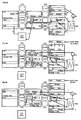
- Figures 4 a - f shows the same retort as Figure 1 but with different pipework to permit hydraulic transfer of product magazines or 'cassettes' and shows the progression of cassettes 1 to 8 passing through that retort.
- the four stages of loading, heating, cooling and unloading are managed in this embodiment alongside the flow of heat transfer fluids for both heat transfer as well as physical transfer of cassettes.
- Figure 4a shows stage 1 with gate valves GV1 and GV3 open.
- the cassette 3 (Cas3) is being transferred from the chamber T10 to the chamber T7 by the pumping of 130C water from chamber T7 to the inlet chamber of piston pump P1 via conduit c.
- the discharge side of the piston pump P1 is transferring water at 130C to the hot well via conduit b.
- the water entering the hotwell at the lower section displaces water from the top section back into chamber T10 via conduit a. All of these transfers are taking place from a base pressure of 3 bar with the pumping action of P1 providing sufficient over/under pressure to ensure hydraulic force sufficient to provide the necessary transfer of the two cassettes being moved.
- Cassette 1 is being withdrawn from chamber T9 and mains water is introduced to the core of cassette 1 to further cool the product contained therein from 40C to 30C.
- the excess water drains into chamber T9 by gravity, cooling the water in chamber T9 to between 20C and 40C.
- Figure 4c shows the end of stage 2, some two minutes after its start.
- the product in the cassette 7 is now around 60C, an increase of 40C from ambient and that in cassette 3 is now around 90C, 40C lower than sterilisation temperature.
- the temperature of product in the cassette 6 is now at almost 130C and the pressure in chamber T2 has been increased to 3bar.
- the final cooling and drying of cassette 1 and its product is achieved by forced air from the axial fan through its core.
- Figure 4d shows stage 3.
- the pressures in T7 and T6 are now equalised enabling the gate valve GV4 to open and cassette 3 to be transferred by the hydraulic action of water being pumped from the discharge side of piston pump P1 at 1.2bar against the lower pressure head of 1.1bar in chamber T8.
- the water flow into chamber T8 is drawn into the suction side of centrifugal pump P3 via conduit m and the heat exchanger x and thence via conduit s into the core of the newly loaded cassette 8 which is at 20C.
- the pressures in chambers T10 and T2 are also equal at 3 bar enabling gate valve GV2 to open and the hydraulic action of water at 90C and 3bar being pumped from P2 via conduit q to the chamber T0 side of chamber T2 to transfer cassette 6 into chamber T10.
- the 90C water in the discharge side of piston pump P2 is pumped into the core of cassette 8 to heat it from 60C. Excess water at 90C is drawn into the inlet side of piston pump P2 from chamber T1.
- the 110C water in the discharge side of piston pump P1 is pumped into the base of the hot well where it is heated to 130C by the boiler (not shown). Mixing of water at 110C and 130C is avoided through the use of baffles within the hot well. Water at 130C is thereby pumped via conduit a into the core of cassette 6 within chamber T10, heating the product contained therein from 110C to 130C.
- Figure 4f is the end of stage 4. Chambers T0, *T1 and T2 are all now at 90C.
Landscapes
- Engineering & Computer Science (AREA)
- Life Sciences & Earth Sciences (AREA)
- Wood Science & Technology (AREA)
- Zoology (AREA)
- Chemical & Material Sciences (AREA)
- Food Science & Technology (AREA)
- Polymers & Plastics (AREA)
- Mechanical Engineering (AREA)
- Health & Medical Sciences (AREA)
- Epidemiology (AREA)
- Animal Behavior & Ethology (AREA)
- General Health & Medical Sciences (AREA)
- Public Health (AREA)
- Veterinary Medicine (AREA)
- Food Preservation Except Freezing, Refrigeration, And Drying (AREA)
- Apparatus For Disinfection Or Sterilisation (AREA)
Priority Applications (1)
| Application Number | Priority Date | Filing Date | Title |
|---|---|---|---|
| EP16192054.1A EP3195735A1 (en) | 2008-09-25 | 2009-09-24 | Heat exchange and transport system for retorting apparatus |
Applications Claiming Priority (3)
| Application Number | Priority Date | Filing Date | Title |
|---|---|---|---|
| GB0817602A GB0817602D0 (en) | 2008-09-25 | 2008-09-25 | Heat exchange system for retorting apparatus |
| GB0817678A GB0817678D0 (en) | 2008-09-26 | 2008-09-26 | Heat exchange and transport syste, for retorting apparatus |
| PCT/GB2009/002315 WO2010035016A1 (en) | 2008-09-25 | 2009-09-24 | Heat exchange and transport system for retorting apparatus |
Related Child Applications (2)
| Application Number | Title | Priority Date | Filing Date |
|---|---|---|---|
| EP16192054.1A Division-Into EP3195735A1 (en) | 2008-09-25 | 2009-09-24 | Heat exchange and transport system for retorting apparatus |
| EP16192054.1A Division EP3195735A1 (en) | 2008-09-25 | 2009-09-24 | Heat exchange and transport system for retorting apparatus |
Publications (2)
| Publication Number | Publication Date |
|---|---|
| EP2343993A1 EP2343993A1 (en) | 2011-07-20 |
| EP2343993B1 true EP2343993B1 (en) | 2016-11-23 |
Family
ID=41347728
Family Applications (2)
| Application Number | Title | Priority Date | Filing Date |
|---|---|---|---|
| EP09785174.5A Not-in-force EP2343993B1 (en) | 2008-09-25 | 2009-09-24 | Heat exchange and transport system for retorting apparatus |
| EP16192054.1A Withdrawn EP3195735A1 (en) | 2008-09-25 | 2009-09-24 | Heat exchange and transport system for retorting apparatus |
Family Applications After (1)
| Application Number | Title | Priority Date | Filing Date |
|---|---|---|---|
| EP16192054.1A Withdrawn EP3195735A1 (en) | 2008-09-25 | 2009-09-24 | Heat exchange and transport system for retorting apparatus |
Country Status (10)
| Country | Link |
|---|---|
| US (1) | US9055756B2 (enExample) |
| EP (2) | EP2343993B1 (enExample) |
| JP (1) | JP5927716B2 (enExample) |
| KR (2) | KR101913021B1 (enExample) |
| CN (1) | CN102202528B (enExample) |
| AU (2) | AU2009295638B2 (enExample) |
| BR (1) | BRPI0919253A2 (enExample) |
| CA (1) | CA2775019A1 (enExample) |
| EA (2) | EA023308B1 (enExample) |
| WO (1) | WO2010035016A1 (enExample) |
Families Citing this family (13)
| Publication number | Priority date | Publication date | Assignee | Title |
|---|---|---|---|---|
| JP2012100572A (ja) * | 2010-11-09 | 2012-05-31 | Tokyo Electric Power Co Inc:The | 殺菌システム |
| JP2012187037A (ja) * | 2011-03-10 | 2012-10-04 | Tokyo Electric Power Co Inc:The | 殺菌システム |
| JP2014529324A (ja) * | 2011-07-21 | 2014-11-06 | ジョン・ビーン・テクノロジーズ・コーポレイションJohn Beantechnologies Corporation | 袋ならびにその他不定形の容器および対象物を処理するためのキャリア |
| JP5838720B2 (ja) * | 2011-10-25 | 2016-01-06 | 大日本印刷株式会社 | 殺菌処理ライン及びその浄化方法 |
| GB201218259D0 (en) * | 2012-10-11 | 2012-11-28 | Continuous Retorts Ltd | A retorting apparatus |
| US20150211805A1 (en) * | 2014-01-29 | 2015-07-30 | Kunshan Jue-Chung Electronics Co., Ltd. | Thermostat module |
| WO2016019068A1 (en) * | 2014-07-30 | 2016-02-04 | Silgan Containers Llc | System for induction heating of metal containers using batch processing |
| US10440979B2 (en) * | 2015-11-11 | 2019-10-15 | Home Tech Innovation, Inc. | Apparatus and methods for at least semi-autonomous meal storage and cooking via fluid immersion |
| JP7731669B2 (ja) | 2017-09-15 | 2025-09-01 | ホーム テック イノベーション,インコーポレイテッド | 少なくとも半自律型の食事の保存及び調理のための装置及び方法 |
| US11582991B2 (en) | 2019-06-03 | 2023-02-21 | John Bean Technologies Corporation | Retort system |
| KR102348216B1 (ko) * | 2019-06-18 | 2022-01-10 | 주식회사 엘지유플러스 | 통신 모뎀 및 이를 포함하는 통신 시스템 및 그 구축 방법 |
| KR102481536B1 (ko) * | 2020-03-02 | 2022-12-26 | 씨제이제일제당 (주) | 살균기 |
| EP4317479B1 (de) * | 2022-08-04 | 2025-03-26 | IAS GmbH | Vorrichtung und verfahren zum vorwärmen von stangenförmigen metallischen werkstücken |
Family Cites Families (18)
| Publication number | Priority date | Publication date | Assignee | Title |
|---|---|---|---|---|
| US3511168A (en) * | 1968-04-22 | 1970-05-12 | Fmc Corp | Apparatus for processing products in sealed containers |
| US3927976A (en) * | 1973-09-26 | 1975-12-23 | Fmc Corp | Containerized hydrostatic sterilizing system |
| US4003302A (en) * | 1974-11-08 | 1977-01-18 | Fmc Corporation | Retort system |
| US4646629A (en) * | 1984-02-10 | 1987-03-03 | Fmc Corporation | Sterilizing apparatus |
| JPH0753519Y2 (ja) * | 1991-12-05 | 1995-12-13 | 株式会社四国総合研究所 | 加熱殺菌装置 |
| JP2549270B2 (ja) * | 1994-03-29 | 1996-10-30 | 株式会社日阪製作所 | バッチ連続式レトルト殺菌装置 |
| JP3372643B2 (ja) * | 1994-03-29 | 2003-02-04 | 株式会社日阪製作所 | バッチ連続式レトルト殺菌装置 |
| JP2549271B2 (ja) * | 1994-03-29 | 1996-10-30 | 株式会社日阪製作所 | バッチ連続式レトルト殺菌装置 |
| EP0691132B1 (en) * | 1994-07-05 | 2001-11-28 | Excalibur Medical (Proprietary) Limited | Autoclave |
| JPH10262344A (ja) * | 1997-03-19 | 1998-09-29 | Mitsumi Electric Co Ltd | 2電源方式リモートコントローラの電源回路 |
| HU225760B1 (en) * | 1997-10-22 | 2007-08-28 | Istvan Boldizsar | Process and apparatus for sterilization of food in bag |
| JP2000069948A (ja) * | 1998-08-31 | 2000-03-07 | Samson Co Ltd | 調理殺菌装置の廃熱回収システム |
| JP2001333753A (ja) * | 2000-05-25 | 2001-12-04 | Coca-Cola West Japan Co Ltd | パストライザ冷却装置 |
| JP3778900B2 (ja) * | 2002-11-21 | 2006-05-24 | 三洋電機株式会社 | 殺菌装置及びこれを用いた水耕栽培システム |
| JP2006000327A (ja) * | 2004-06-16 | 2006-01-05 | Sanyo Electric Co Ltd | 処理装置 |
| JP4587964B2 (ja) | 2006-01-31 | 2010-11-24 | 関西電力株式会社 | 殺菌用加熱・冷却装置 |
| GB0706334D0 (en) * | 2007-03-31 | 2007-05-09 | Lambert David | Retorting apparatus and method |
| JP2008043781A (ja) * | 2007-09-27 | 2008-02-28 | Sanyo Electric Co Ltd | ヒートポンプ装置を用いた殺菌処理装置 |
-
2009
- 2009-09-24 EA EA201170482A patent/EA023308B1/ru not_active IP Right Cessation
- 2009-09-24 EA EA201500963A patent/EA201500963A1/ru unknown
- 2009-09-24 CA CA2775019A patent/CA2775019A1/en not_active Abandoned
- 2009-09-24 JP JP2011528420A patent/JP5927716B2/ja not_active Expired - Fee Related
- 2009-09-24 BR BRPI0919253A patent/BRPI0919253A2/pt not_active Application Discontinuation
- 2009-09-24 WO PCT/GB2009/002315 patent/WO2010035016A1/en not_active Ceased
- 2009-09-24 EP EP09785174.5A patent/EP2343993B1/en not_active Not-in-force
- 2009-09-24 KR KR1020167029135A patent/KR101913021B1/ko not_active Expired - Fee Related
- 2009-09-24 EP EP16192054.1A patent/EP3195735A1/en not_active Withdrawn
- 2009-09-24 AU AU2009295638A patent/AU2009295638B2/en not_active Ceased
- 2009-09-24 US US13/120,995 patent/US9055756B2/en not_active Expired - Fee Related
- 2009-09-24 KR KR1020117009269A patent/KR20110074994A/ko not_active Ceased
- 2009-09-24 CN CN200980142542.XA patent/CN102202528B/zh not_active Expired - Fee Related
-
2017
- 2017-08-01 AU AU2017210524A patent/AU2017210524B2/en not_active Ceased
Also Published As
| Publication number | Publication date |
|---|---|
| WO2010035016A1 (en) | 2010-04-01 |
| CA2775019A1 (en) | 2010-04-01 |
| KR20110074994A (ko) | 2011-07-05 |
| US20110180232A1 (en) | 2011-07-28 |
| HK1157578A1 (en) | 2012-07-06 |
| AU2017210524A1 (en) | 2017-08-17 |
| JP5927716B2 (ja) | 2016-06-01 |
| BRPI0919253A2 (pt) | 2016-07-12 |
| KR101913021B1 (ko) | 2019-01-14 |
| CN102202528B (zh) | 2015-03-25 |
| EA201170482A1 (ru) | 2011-12-30 |
| KR20160125528A (ko) | 2016-10-31 |
| EA023308B1 (ru) | 2016-05-31 |
| CN102202528A (zh) | 2011-09-28 |
| AU2009295638B2 (en) | 2015-07-30 |
| US9055756B2 (en) | 2015-06-16 |
| EP2343993A1 (en) | 2011-07-20 |
| JP2012503482A (ja) | 2012-02-09 |
| AU2017210524B2 (en) | 2018-09-27 |
| EA201500963A1 (ru) | 2017-04-28 |
| AU2009295638A1 (en) | 2010-04-01 |
| EP3195735A1 (en) | 2017-07-26 |
Similar Documents
| Publication | Publication Date | Title |
|---|---|---|
| EP2343993B1 (en) | Heat exchange and transport system for retorting apparatus | |
| CN101909789B (zh) | 热等静压装置 | |
| ES2289374T3 (es) | Metodo de pasteurizacion de una superficie. | |
| JP2012503482A5 (enExample) | ||
| JP2007313309A (ja) | 対象物を処理するための方法と装置 | |
| US8444931B2 (en) | Retorting apparatus and method | |
| AU2015249204A1 (en) | Heat exchange and transport system for retorting apparatus | |
| AU2017383035B2 (en) | Apparatus for heat shrinking a package and method for heat shrinking a package | |
| JPH02245146A (ja) | 高圧処理装置 | |
| CN114502500B (zh) | 用于热灌装液体产品的方法及设备 | |
| EP4027805B1 (en) | A continuous retort | |
| HK1157578B (en) | Heat exchange and transport system for retorting apparatus | |
| JP7249104B2 (ja) | 低温殺菌設備及びこの低温殺菌設備を動作させる方法 | |
| US7347004B1 (en) | Freeze drying apparatus and method | |
| JP5722416B2 (ja) | 熱間静水圧プレス装置 | |
| WO2016059438A1 (en) | Multiple retort | |
| US20070294912A1 (en) | Integrated heater/cooler | |
| JPS6034387B2 (ja) | 回転式高温殺菌装置 |
Legal Events
| Date | Code | Title | Description |
|---|---|---|---|
| PUAI | Public reference made under article 153(3) epc to a published international application that has entered the european phase |
Free format text: ORIGINAL CODE: 0009012 |
|
| 17P | Request for examination filed |
Effective date: 20110414 |
|
| AK | Designated contracting states |
Kind code of ref document: A1 Designated state(s): AT BE BG CH CY CZ DE DK EE ES FI FR GB GR HR HU IE IS IT LI LT LU LV MC MK MT NL NO PL PT RO SE SI SK SM TR |
|
| AX | Request for extension of the european patent |
Extension state: AL BA RS |
|
| DAX | Request for extension of the european patent (deleted) | ||
| 17Q | First examination report despatched |
Effective date: 20120808 |
|
| GRAP | Despatch of communication of intention to grant a patent |
Free format text: ORIGINAL CODE: EPIDOSNIGR1 |
|
| INTG | Intention to grant announced |
Effective date: 20160622 |
|
| GRAS | Grant fee paid |
Free format text: ORIGINAL CODE: EPIDOSNIGR3 |
|
| GRAA | (expected) grant |
Free format text: ORIGINAL CODE: 0009210 |
|
| AK | Designated contracting states |
Kind code of ref document: B1 Designated state(s): AT BE BG CH CY CZ DE DK EE ES FI FR GB GR HR HU IE IS IT LI LT LU LV MC MK MT NL NO PL PT RO SE SI SK SM TR |
|
| REG | Reference to a national code |
Ref country code: GB Ref legal event code: FG4D |
|
| REG | Reference to a national code |
Ref country code: CH Ref legal event code: EP |
|
| REG | Reference to a national code |
Ref country code: IE Ref legal event code: FG4D |
|
| REG | Reference to a national code |
Ref country code: AT Ref legal event code: REF Ref document number: 847020 Country of ref document: AT Kind code of ref document: T Effective date: 20161215 |
|
| REG | Reference to a national code |
Ref country code: DE Ref legal event code: R096 Ref document number: 602009042648 Country of ref document: DE |
|
| PG25 | Lapsed in a contracting state [announced via postgrant information from national office to epo] |
Ref country code: LV Free format text: LAPSE BECAUSE OF FAILURE TO SUBMIT A TRANSLATION OF THE DESCRIPTION OR TO PAY THE FEE WITHIN THE PRESCRIBED TIME-LIMIT Effective date: 20161123 |
|
| REG | Reference to a national code |
Ref country code: LT Ref legal event code: MG4D |
|
| REG | Reference to a national code |
Ref country code: NL Ref legal event code: MP Effective date: 20161123 |
|
| REG | Reference to a national code |
Ref country code: AT Ref legal event code: MK05 Ref document number: 847020 Country of ref document: AT Kind code of ref document: T Effective date: 20161123 |
|
| PG25 | Lapsed in a contracting state [announced via postgrant information from national office to epo] |
Ref country code: SE Free format text: LAPSE BECAUSE OF FAILURE TO SUBMIT A TRANSLATION OF THE DESCRIPTION OR TO PAY THE FEE WITHIN THE PRESCRIBED TIME-LIMIT Effective date: 20161123 Ref country code: NO Free format text: LAPSE BECAUSE OF FAILURE TO SUBMIT A TRANSLATION OF THE DESCRIPTION OR TO PAY THE FEE WITHIN THE PRESCRIBED TIME-LIMIT Effective date: 20170223 Ref country code: GR Free format text: LAPSE BECAUSE OF FAILURE TO SUBMIT A TRANSLATION OF THE DESCRIPTION OR TO PAY THE FEE WITHIN THE PRESCRIBED TIME-LIMIT Effective date: 20170224 Ref country code: NL Free format text: LAPSE BECAUSE OF FAILURE TO SUBMIT A TRANSLATION OF THE DESCRIPTION OR TO PAY THE FEE WITHIN THE PRESCRIBED TIME-LIMIT Effective date: 20161123 Ref country code: LT Free format text: LAPSE BECAUSE OF FAILURE TO SUBMIT A TRANSLATION OF THE DESCRIPTION OR TO PAY THE FEE WITHIN THE PRESCRIBED TIME-LIMIT Effective date: 20161123 |
|
| PG25 | Lapsed in a contracting state [announced via postgrant information from national office to epo] |
Ref country code: ES Free format text: LAPSE BECAUSE OF FAILURE TO SUBMIT A TRANSLATION OF THE DESCRIPTION OR TO PAY THE FEE WITHIN THE PRESCRIBED TIME-LIMIT Effective date: 20161123 Ref country code: FI Free format text: LAPSE BECAUSE OF FAILURE TO SUBMIT A TRANSLATION OF THE DESCRIPTION OR TO PAY THE FEE WITHIN THE PRESCRIBED TIME-LIMIT Effective date: 20161123 Ref country code: PT Free format text: LAPSE BECAUSE OF FAILURE TO SUBMIT A TRANSLATION OF THE DESCRIPTION OR TO PAY THE FEE WITHIN THE PRESCRIBED TIME-LIMIT Effective date: 20170323 Ref country code: PL Free format text: LAPSE BECAUSE OF FAILURE TO SUBMIT A TRANSLATION OF THE DESCRIPTION OR TO PAY THE FEE WITHIN THE PRESCRIBED TIME-LIMIT Effective date: 20161123 Ref country code: HR Free format text: LAPSE BECAUSE OF FAILURE TO SUBMIT A TRANSLATION OF THE DESCRIPTION OR TO PAY THE FEE WITHIN THE PRESCRIBED TIME-LIMIT Effective date: 20161123 Ref country code: AT Free format text: LAPSE BECAUSE OF FAILURE TO SUBMIT A TRANSLATION OF THE DESCRIPTION OR TO PAY THE FEE WITHIN THE PRESCRIBED TIME-LIMIT Effective date: 20161123 |
|
| PG25 | Lapsed in a contracting state [announced via postgrant information from national office to epo] |
Ref country code: DK Free format text: LAPSE BECAUSE OF FAILURE TO SUBMIT A TRANSLATION OF THE DESCRIPTION OR TO PAY THE FEE WITHIN THE PRESCRIBED TIME-LIMIT Effective date: 20161123 Ref country code: RO Free format text: LAPSE BECAUSE OF FAILURE TO SUBMIT A TRANSLATION OF THE DESCRIPTION OR TO PAY THE FEE WITHIN THE PRESCRIBED TIME-LIMIT Effective date: 20161123 Ref country code: SK Free format text: LAPSE BECAUSE OF FAILURE TO SUBMIT A TRANSLATION OF THE DESCRIPTION OR TO PAY THE FEE WITHIN THE PRESCRIBED TIME-LIMIT Effective date: 20161123 Ref country code: CZ Free format text: LAPSE BECAUSE OF FAILURE TO SUBMIT A TRANSLATION OF THE DESCRIPTION OR TO PAY THE FEE WITHIN THE PRESCRIBED TIME-LIMIT Effective date: 20161123 Ref country code: EE Free format text: LAPSE BECAUSE OF FAILURE TO SUBMIT A TRANSLATION OF THE DESCRIPTION OR TO PAY THE FEE WITHIN THE PRESCRIBED TIME-LIMIT Effective date: 20161123 |
|
| REG | Reference to a national code |
Ref country code: DE Ref legal event code: R097 Ref document number: 602009042648 Country of ref document: DE |
|
| PG25 | Lapsed in a contracting state [announced via postgrant information from national office to epo] |
Ref country code: BG Free format text: LAPSE BECAUSE OF FAILURE TO SUBMIT A TRANSLATION OF THE DESCRIPTION OR TO PAY THE FEE WITHIN THE PRESCRIBED TIME-LIMIT Effective date: 20170223 Ref country code: SM Free format text: LAPSE BECAUSE OF FAILURE TO SUBMIT A TRANSLATION OF THE DESCRIPTION OR TO PAY THE FEE WITHIN THE PRESCRIBED TIME-LIMIT Effective date: 20161123 Ref country code: IT Free format text: LAPSE BECAUSE OF FAILURE TO SUBMIT A TRANSLATION OF THE DESCRIPTION OR TO PAY THE FEE WITHIN THE PRESCRIBED TIME-LIMIT Effective date: 20161123 Ref country code: BE Free format text: LAPSE BECAUSE OF FAILURE TO SUBMIT A TRANSLATION OF THE DESCRIPTION OR TO PAY THE FEE WITHIN THE PRESCRIBED TIME-LIMIT Effective date: 20161123 |
|
| PLBE | No opposition filed within time limit |
Free format text: ORIGINAL CODE: 0009261 |
|
| STAA | Information on the status of an ep patent application or granted ep patent |
Free format text: STATUS: NO OPPOSITION FILED WITHIN TIME LIMIT |
|
| 26N | No opposition filed |
Effective date: 20170824 |
|
| PG25 | Lapsed in a contracting state [announced via postgrant information from national office to epo] |
Ref country code: SI Free format text: LAPSE BECAUSE OF FAILURE TO SUBMIT A TRANSLATION OF THE DESCRIPTION OR TO PAY THE FEE WITHIN THE PRESCRIBED TIME-LIMIT Effective date: 20161123 |
|
| REG | Reference to a national code |
Ref country code: DE Ref legal event code: R119 Ref document number: 602009042648 Country of ref document: DE |
|
| REG | Reference to a national code |
Ref country code: CH Ref legal event code: PL |
|
| GBPC | Gb: european patent ceased through non-payment of renewal fee |
Effective date: 20170924 |
|
| PG25 | Lapsed in a contracting state [announced via postgrant information from national office to epo] |
Ref country code: MC Free format text: LAPSE BECAUSE OF FAILURE TO SUBMIT A TRANSLATION OF THE DESCRIPTION OR TO PAY THE FEE WITHIN THE PRESCRIBED TIME-LIMIT Effective date: 20161123 |
|
| REG | Reference to a national code |
Ref country code: IE Ref legal event code: MM4A |
|
| PG25 | Lapsed in a contracting state [announced via postgrant information from national office to epo] |
Ref country code: LU Free format text: LAPSE BECAUSE OF NON-PAYMENT OF DUE FEES Effective date: 20170924 |
|
| REG | Reference to a national code |
Ref country code: FR Ref legal event code: ST Effective date: 20180531 |
|
| PG25 | Lapsed in a contracting state [announced via postgrant information from national office to epo] |
Ref country code: LI Free format text: LAPSE BECAUSE OF NON-PAYMENT OF DUE FEES Effective date: 20170930 Ref country code: CH Free format text: LAPSE BECAUSE OF NON-PAYMENT OF DUE FEES Effective date: 20170930 Ref country code: IE Free format text: LAPSE BECAUSE OF NON-PAYMENT OF DUE FEES Effective date: 20170924 Ref country code: GB Free format text: LAPSE BECAUSE OF NON-PAYMENT OF DUE FEES Effective date: 20170924 Ref country code: DE Free format text: LAPSE BECAUSE OF NON-PAYMENT OF DUE FEES Effective date: 20180404 |
|
| PG25 | Lapsed in a contracting state [announced via postgrant information from national office to epo] |
Ref country code: FR Free format text: LAPSE BECAUSE OF NON-PAYMENT OF DUE FEES Effective date: 20171002 |
|
| PG25 | Lapsed in a contracting state [announced via postgrant information from national office to epo] |
Ref country code: MT Free format text: LAPSE BECAUSE OF NON-PAYMENT OF DUE FEES Effective date: 20170924 |
|
| PG25 | Lapsed in a contracting state [announced via postgrant information from national office to epo] |
Ref country code: HU Free format text: LAPSE BECAUSE OF FAILURE TO SUBMIT A TRANSLATION OF THE DESCRIPTION OR TO PAY THE FEE WITHIN THE PRESCRIBED TIME-LIMIT; INVALID AB INITIO Effective date: 20090924 |
|
| PG25 | Lapsed in a contracting state [announced via postgrant information from national office to epo] |
Ref country code: CY Free format text: LAPSE BECAUSE OF NON-PAYMENT OF DUE FEES Effective date: 20161123 |
|
| PG25 | Lapsed in a contracting state [announced via postgrant information from national office to epo] |
Ref country code: MK Free format text: LAPSE BECAUSE OF FAILURE TO SUBMIT A TRANSLATION OF THE DESCRIPTION OR TO PAY THE FEE WITHIN THE PRESCRIBED TIME-LIMIT Effective date: 20161123 |
|
| PG25 | Lapsed in a contracting state [announced via postgrant information from national office to epo] |
Ref country code: TR Free format text: LAPSE BECAUSE OF FAILURE TO SUBMIT A TRANSLATION OF THE DESCRIPTION OR TO PAY THE FEE WITHIN THE PRESCRIBED TIME-LIMIT Effective date: 20161123 |
|
| PG25 | Lapsed in a contracting state [announced via postgrant information from national office to epo] |
Ref country code: IS Free format text: LAPSE BECAUSE OF FAILURE TO SUBMIT A TRANSLATION OF THE DESCRIPTION OR TO PAY THE FEE WITHIN THE PRESCRIBED TIME-LIMIT Effective date: 20170323 |