EP2343411A1 - Wäschetrockner mit Wärmepumpe - Google Patents
Wäschetrockner mit Wärmepumpe Download PDFInfo
- Publication number
- EP2343411A1 EP2343411A1 EP10000066A EP10000066A EP2343411A1 EP 2343411 A1 EP2343411 A1 EP 2343411A1 EP 10000066 A EP10000066 A EP 10000066A EP 10000066 A EP10000066 A EP 10000066A EP 2343411 A1 EP2343411 A1 EP 2343411A1
- Authority
- EP
- European Patent Office
- Prior art keywords
- compressor
- clothes dryer
- capsule housing
- motor
- drum
- Prior art date
- Legal status (The legal status is an assumption and is not a legal conclusion. Google has not performed a legal analysis and makes no representation as to the accuracy of the status listed.)
- Granted
Links
- 239000003507 refrigerant Substances 0.000 claims abstract description 20
- 239000002775 capsule Substances 0.000 claims description 28
- 230000008878 coupling Effects 0.000 claims description 20
- 238000010168 coupling process Methods 0.000 claims description 20
- 238000005859 coupling reaction Methods 0.000 claims description 20
- 238000000034 method Methods 0.000 claims description 16
- 238000001035 drying Methods 0.000 claims description 10
- 230000005540 biological transmission Effects 0.000 claims description 6
- 238000010438 heat treatment Methods 0.000 claims description 6
- 238000001816 cooling Methods 0.000 description 7
- 239000002918 waste heat Substances 0.000 description 4
- 238000009434 installation Methods 0.000 description 2
- 238000007906 compression Methods 0.000 description 1
- 238000009833 condensation Methods 0.000 description 1
- 230000005494 condensation Effects 0.000 description 1
- 230000001419 dependent effect Effects 0.000 description 1
- 238000012986 modification Methods 0.000 description 1
- 230000004048 modification Effects 0.000 description 1
- 230000000149 penetrating effect Effects 0.000 description 1
- 230000035515 penetration Effects 0.000 description 1
Images


Classifications
-
- D—TEXTILES; PAPER
- D06—TREATMENT OF TEXTILES OR THE LIKE; LAUNDERING; FLEXIBLE MATERIALS NOT OTHERWISE PROVIDED FOR
- D06F—LAUNDERING, DRYING, IRONING, PRESSING OR FOLDING TEXTILE ARTICLES
- D06F58/00—Domestic laundry dryers
- D06F58/20—General details of domestic laundry dryers
- D06F58/206—Heat pump arrangements
Definitions
- the invention relates to a tumble dryer comprising a arranged in a housing, driven by a motor, rotatably mounted on a horizontal or inclined axis drum, a closed process air circuit in which supplied by means of a process air blower drying air via an air inlet of the drum, via an air outlet from this discharged, dehumidified in a heat exchanger and then reheated by a heater, a heat pump device with a refrigerant circuit, wherein the refrigerant in a piping system with an evaporator, a compressor with a compressor which is surrounded by a capsule housing substantially gas-tight, a condenser and circulates a throttle, wherein the heat exchanger containing the evaporator and the heater, the condenser of the heat pump.
- the heat from the engine heats the refrigerant more and more, which means that the entire process has to be heated more and more and finally waste heat has to be blown out of the dryer.
- blowers that cool the compressor with air, but which are quite inefficient, since the capsule housing does not allow direct supply of cooling air to the compressor motor.
- Another possibility is to cool the refrigerant line by means of cooling fins and / or a fan, which acts on the refrigerant line with cooling air, whereby waste heat passes out of the dryer. This arrangement is a little more complex and requires space in the device housing.
- the invention thus has the object to provide an efficient clothes dryer with a simply constructed heat pump.
- the advantage achieved with the invention is that less so-called waste heat passes into the refrigerant circuit, so that no additional measures for cooling are necessary in the refrigerant circuit.
- the refrigerant circuit requires less space, so that a particularly compact arrangement is made possible here.
- the energy used for the drying process is used more efficiently, so that the dryer emits less heat into the installation room, which is particularly desirable in living spaces.
- the engine is mounted outside the compressor and adapted to drive the drum and the process air blower, and further to transmit the driving force into the capsule housing to the compressor.
- a single, high-quality engine with a good efficiency for all drive tasks can be used.
- less heat is generated in the compressor within the capsule housing, because no motor is arranged here.
- the friction properties of the compressor and the compression process only produce heat of low intensity, so that it no longer has to be cooled.
- the motor comprises a shaft for driving the drum and the process air blower, which forms the drive for the compressor in the axial extension.
- the axially elongated shaft portion of the capsule housing of the compressor is arranged penetrating and coupled within the capsule housing with the compressor.
- the passage through the wall of the capsule housing is in this case sealed with a shaft seal.
- a coupling is provided on the shaft section provided for driving the compressor, which can interrupt or connect the transmission of the rotational movement to the compressor.
- the shaft portion is formed on the outside in front of the capsule housing ending, wherein at this end outside of the capsule housing, a first coupling element is mounted, which is adapted to cooperate with a disposed within the capsule housing second coupling element, wherein the second coupling element is adapted to transmit the rotational movement to the compressor.
- a first coupling element is mounted, which is adapted to cooperate with a disposed within the capsule housing second coupling element, wherein the second coupling element is adapted to transmit the rotational movement to the compressor.
- the coupling is expedient to form the coupling as a magnetic coupling, wherein the capsule housing is adapted to leave the effective range of the magnetic coupling unaffected.
- the magnetic coupling is designed to be electrically operated. As a result, a particularly simple and reliable operation of the clutch is provided.
- the tumble dryer with a control device which is adapted to control the magnetic coupling, so that depending on the course of the drying process, the compressor is active or inactive, with permanently activated motor.
- the provision of heat and cooling for dehumidifying can be changed even with permanently rotating motor shaft, for a controlled course of the drying process.
- an additional electric heater to arrange in the vicinity of the compressor or in the compressor, such as in the so-called oil sump, for heating the compressor as required or a refrigerant line.
- the heating device can be switched on for a limited time, expediently for 10 to 20 minutes. Thereafter, the additional heater is switched off, during which time the refrigerant circuit runs self-regulating stable.
- the heat pump device it is expedient to arrange the heat pump device, the motor and the process air blower in a compact functional module of the tumble dryer.
- the training has proven to be advantageous as a bottom-side functional module.
- the Fig. 1 shows in the perspective of a tumble dryer 1.
- the tumble dryer 1 in this case comprises a housing 2 in which a rotatably mounted drum 3 is arranged.
- the three figures each show the clothes dryer 1 in the closed situation.
- In the housing 2 is located on the bottom side below the drum 3, based on the proper operation
- the functional module 5 which receives the components for the heat pump, the blower and the drive of the drum 3.
- the process air PL is generated by means of a blower and fed to the air inlet 6 of the drum 3.
- the drying air PL passes from the drum 3 in the bottom module 5, in which in a channel 8 of the heat exchanger 15 (FIG. Fig. 3 ) for cooling and condensation of the process air and the heater 16 ( Fig. 3 ) are arranged for heating the process air PL.
- Fig. 2 shows the function module 5 alone.
- the channel 8 can be seen, in which the heat exchanger 15 and the radiator 16 are located, which are components of the heat pump.
- the air outlet 7 receives the moist, exhausted process air PL, wherein the fan 9, the flow of the process air PL provides.
- the motor 10 drives the fan 9 and provides the rotational movement of the drum 3 by means of the drum drive 12.
- the motor shaft 11 has an axially elongated shaft portion 11 a, which is guided through the capsule housing 13 to the interior of the compressor 14. There, this shaft section 11a drives the compressor 14a, which is enclosed in a gas-tight manner by the capsule housing 13.
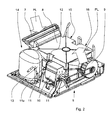
- Fig. 3 schematically shows the structure of the functional module 5.
- the channel 8 skizzert, in which the cooling evaporator (heat exchanger) 15 and the downstream condenser (radiator) 16 are located.
- a throttle body 15 a is arranged to provide the function of the heat pump together with the compressor 14.
- the fan 9 is driven by the motor 10, wherein in this example, due to the paraxial arrangement of the fan 9 to the motor 10, a belt drive is used for power transmission.
- On the motor 10 and the drum drive 12 is mounted, with a to the drum 3 ( Fig. 1 ) belt is provided.
- the engine 10 further includes an axially elongated shaft portion 11a which provides rotational movement for the compressor 14a.
- the compressor 14a is located within the capsule housing 13 of the compressor 14.
- the shaft portion 11a terminates outside of the capsule housing 13, wherein at the end a first coupling element 17a is attached.
- the second coupling element 17b Within the capsule housing 13 is the second coupling element 17b, which is taken along by magnetic force transmission from the rotation of the first coupling element 17a, so that the rotational movement is transmitted to the interior of the capsule housing 13 to the compressor 14a.
- the magnetically acting force is provided electrically, so that by means of the control device 19 (FIG. Fig. 1 ) the engagement or disengagement can be controlled.
- a heating device 20 is arranged spatially close to the compressor in order to bring heat into the refrigerant circuit via the compressor 14.
- the heater 20 is also switched on or off by the control device 19, so that the Drying process, if necessary, can be adapted to the laundry items and the current state of drying of the laundry.
- the fan 9 a is also mounted on the shaft 11 and serves to cool the engine 10.
Landscapes
- Engineering & Computer Science (AREA)
- Textile Engineering (AREA)
- Detail Structures Of Washing Machines And Dryers (AREA)
Abstract
Description
- Die Erfindung betrifft einen Wäschetrockner, umfassend eine in einem Gehäuse angeordneten, mittels eines Motors antreibbaren, über eine horizontale oder geneigten Achse drehbar gelagerten Trommel, einen geschlossenen Prozessluftkreislauf, in dem mittels eines Prozessluftgebläses Trocknungsluft über einen Lufteinlass der Trommel zugeführt, über einen Luftauslass aus dieser abgeführt, in einem Wärmetauscher entfeuchtet und danach durch eine Heizung wieder erwärmt wird, einer Wärmepumpeneinrichtung mit einem Kältemittelkreislauf, bei dem Kältemittel in einem Leitungssystem mit einem Verdampfer, einem Kompressor mit einem Verdichter, der von einem Kapselgehäuse im Wesentlichen gasdicht umgeben ist, einem Verflüssiger und einer Drossel zirkuliert, wobei der Wärmetauscher den Verdampfer und die Heizung den Verflüssiger der Wärmepumpe enthält.
- Aus dem Stand der Technik ist gemäß der
EP 1 209 277 A2 ein derartiger Wäschetrockner mit einer Wärmepumpe bekannt. Wärmepumpenwäschetrockner sind momentan besonders begehrt, da sie sowohl die von der Wärmepumpe bereitgestellte Wärme als auch die entsprechend erzeugte Kälte nutzen. Dadurch kann der Energieeinsatz effizienter genutzt werden. Um zu vermeiden, dass Kältemittel nach außen dringt, wurde in den letzten Jahren immer höherer Aufwand hinsichtlich der Dichtigkeit des Kältemittelkreislaufs getrieben. So ist auch der Kompressor mit einem Kapselgehäuse versehen, in dem der Motor für den Antrieb des Verdichters und der Verdichter selbst gasdicht umschlossen ist. Dadurch kann aus dem Verdichter entweichendes Kältemittel nicht in die Umgebung gelangen, es verbleibt im Kapselgehäuse. Bei dieser bewährten Ausführung erwärmt sich durch die Abwärme des Motors das Kältemittel immer stärker, wodurch der gesamte Prozess immer stärker erwärmt und letztendlich Abwärme aus dem Trockner herausgeblasen werden muss. Bekannt sind hierzu Gebläse, die den Kompressor mit Luft kühlen, die jedoch recht ineffizient sind, da das Kapselgehäuse keine direkte Zufuhr der Kühlluft zum Kompressormotor zulässt. Eine andere Möglichkeit ist, die Kältemittelleitung mittels Kühlrippen und/oder einem Gebläse, welches die Kältemittelleitung mit Kühlluft beaufschlagt, zu kühlen, wodurch Abwärme aus dem Trockner heraus gelangt. Diese Anordnung ist etwas aufwändiger und benötigt Bauraum im Gerätegehäuse. - Der Erfindung stellt sich somit die Aufgabe, einen effizienten Wäschetrockner mit einer einfach aufgebauten Wärmepumpe bereitzustellen.
- Erfindungsgemäß wird diese Aufgabe durch einen Wäschetrockner mit den Merkmalen des unabhängigen Anspruchs 1 gelöst. Vorteilhafte Ausgestaltungen und Weiterbildungen der Erfindung ergeben sich aus den nachfolgenden abhängigen Ansprüchen.
- Der mit der Erfindung erreichte Vorteil besteht darin, dass weniger sogenannte Abwärme in den Kältemittelkreislauf gelangt, so dass im Kältemittelkreislauf keine zusätzlichen Maßnahmen zur Kühlung notwendig sind. Dadurch benötigt der Kältemittelkreislauf weniger Bauraum, so dass hier eine besonders kompakte Anordnung ermöglicht wird. Ferner wird durch die Verringerung der Abwärme die eingesetzte Energie für den Trocknungsprozess effizienter genutzt, so dass der Trockner weniger Wärme in den Aufstellraum abgibt, was besonders in Wohnräumen erwünscht ist.
- Gemäß der Erfindung ist der Motor außerhalb des Kompressors angebracht und dazu eingerichtet, die Trommel und das Prozessluftgebläse anzutreiben, und ferner die Antriebskraft in das Kapselgehäuse hinein zum Verdichter zu übertragen. Damit kann ein einziger, hochwertiger Motor mit einem guten Wirkungsgrad für alle Antriebsaufgaben eingesetzt werden. Ferner wird im Kompressor innerhalb des Kapselgehäuses weniger Wärme erzeugt, weil hier kein Motor mehr angeordnet ist. Im Kompressor entsteht aus den Reibungseigenschaften des Verdichters und dem Verdichtungsprozess nur noch Wärme von geringer Intensität, so dass dieser nicht mehr gekühlt werden muss.
- In einer vorteilhaften Weiterbildung umfasst der Motor eine Welle zum Antrieb der Trommel und des Prozessluftgebläses, die in axialer Verlängerung den Antrieb für den Kompressor bildet.
- Damit wird ein einziger, kompakter Antriebsstrang gebildet, der keine weiteren Übertragungsmittel, wie Getriebe enthält und dadurch wenig Bauraum benötigt.
- In einer weiteren zweckmäßigen Weiterbildung ist der axial verlängerte Wellenabschnitt des Kapselgehäuses des Kompressors durchdringend angeordnet und innerhalb des Kapselgehäuses mit dem Verdichter gekoppelt. Der Durchtritt durch die Wandung des Kapselgehäuses ist hierbei mit einer Wellendichtung abgedichtet.
- In einer weiteren, vorteilhaften Ausführung ist an dem für den Antrieb des Kompressors vorgesehenen Wellenabschnitt eine Kupplung angebracht, die die Übertragung der Drehbewegung zum Verdichter unterbrechen oder verbinden kann. Dadurch kann der Verdichter bedarfsweise aktiviert werden.
- In einer vorteilhaften Weiterbildung ist der Wellenabschnitt außenseitig vor dem Kapselgehäuse endend ausgebildet, wobei an diesem Ende außerhalb des Kapselgehäuses ein erstes Kupplungselement angebracht ist, das dazu eingerichtet ist, mit einem innerhalb des Kapselgehäuses angeordnetem zweiten Kupplungselement zusammenzuwirken, wobei das zweite Kupplungselement dazu ausgebildet ist, die Drehbewegung zum Verdichter zu übertragen. Bei dieser Ausführung ist keine Dichtung für die Welle in der Wandung des Kapselgehäuses nötig, weil keine Durchdringung mehr stattfindet.
- Hierbei ist es zweckmäßig, die Kupplung als Magnetkupplung auszubilden, wobei das Kapselgehäuse dazu ausgebildet ist, den Wirkbereich der Magnetkupplung unbeeinflusst zu lassen.
- In einer zweckmäßigen Weiterbildung ist die Magnetkupplung elektrisch betätigbar ausgeführt. Dadurch wird eine besonders einfache und zuverlässige Betätigung der Kupplung bereitgestellt.
- Insgesamt ist es zweckmäßig, den Wäschetrockner mit einer Steuereinrichtung zu versehen, die dazu eingerichtet ist, die Magnetkupplung zu steuern, so dass in Abhängigkeit des Verlaufs des Trocknungsprozesses der Verdichter aktiv oder inaktiv ist, bei dauerhaft aktiviertem Motor. Hierdurch kann die Bereitstellung der Wärme und der Kühlung zum Luftentfeuchten auch bei dauerhaft drehender Motorwelle verändert werden, für einen gesteuerten Verlauf des Trocknungsprozesses.
- Da im Kompressor weniger Wärme entsteht, ist es für eine schnelle Aufheizung des Kältemittels zweckmäßig, eine zusätzliche, elektrische Heizeinrichtung, die in der Nähe des Kompressors oder im Kompressor, wie beispielsweise im sogenannten Ölsumpf, zum bedarfsweisen Aufheizen des Kompressors oder einer Kältemittelleitung anzuordnen. So kann zu Beginn des Trockungsprozesses die Heizeinrichtung für eine begrenzte Zeit eingeschaltet werden, zweckmäßigerweise für 10 bis 20 Minuten. Danach wird die Zusatzheizung abgeschaltet, wobei in dieser Zeit der Kältemittelkreislauf selbstregelnd stabil abläuft.
- Insgesamt ist es zweckmäßig, die Wärmepumpeneinrichtung, den Motor und das Prozessluftgebläse in einem kompakten Funktionsmodul des Wäschetrockners anzuordnen. Hierbei hat sich die Ausbildung als bodenseitiges Funktionsmodul als vorteilhaft erwiesen.
- Ein Ausführungsbeispiel der Erfindung ist in den Zeichnungen rein schematisch dargestellt und wird nachfolgend näher beschrieben. Es zeigt:
- Fig. 1:
- eine perspektivische Darstellung eines Wäschetrockners und
- Fig. 2:
- eine schematische Darstellung der Komponenten der Wärmepumpe
- Die
Fig. 1 zeigt in der Perspektive einen Wäschetrockner 1. Der Wäschetrockner 1 umfasst hierbei ein Gehäuse 2 in dem eine drehbar gelagerte Trommel 3 angeordnet ist. Die drei Figuren zeigen jeweils den Wäschetrockner 1 in der geschlossenen Situation. In dem Gehäuse 2 befindet sich bodenseitig unterhalb der Trommel 3, bezogen auf die betriebsgemäße - Aufstellposition des Trockners, das Funktionsmodul 5, das die Komponenten für die Wärmepumpe, das Gebläse und den Antrieb der Trommel 3 aufnimmt. Im Funktionsmodul 5 wird die Prozessluft PL mittels eines Gebläses erzeugt und zum Lufteinlass 6 der Trommel 3 zugeführt. Durch den Luftauslass 7 gelangt die Trocknungsluft PL aus der Trommel 3 in das Bodenmodul 5, in dem in einem Kanal 8 der Wärmetauscher 15 (
Fig. 3 ) zur Abkühlung und Kondensation der Prozessluft und die Heizung 16 (Fig. 3 ) zum Erwärmen der Prozessluft PL angeordnet sind. -
Fig. 2 zeigt das Funktionsmodul 5 für sich allein. Hier ist der Kanal 8 zu erkennen, in dem sich der Wärmetauscher 15 und der Heizkörper 16 befinden, die Bestandteile der Wärmepumpe sind. Der Luftauslass 7 nimmt die feuchte, aufgebrauchte Prozessluft PL auf, wobei das Gebläse 9 die Strömung der Prozessluft PL bereitstellt. Der Motor 10 treibt das Gebläse 9 an und stellt die Drehbewegung der Trommel 3 mittels des Trommelantriebs 12 bereit. Die Motorwelle 11 besitzt einen axial verlängerten Wellenabschnitt 11a, der durch das Kapselgehäuse 13 hindurch zum Inneren des Kompressors 14 geführt ist. Dort treibt dieser Wellenabschnitt 11a den vom Kapselgehäuse 13 gasdicht umschlossenen Verdichter 14a an. -
Fig. 3 zeigt schematisch den Aufbau des Funktionsmoduls 5. Hier ist der Kanal 8 skizzert, in dem sich der kühlende Verdampfer (Wärmetauscher) 15 und der nachgeschaltete Verflüssiger (Heizkörper) 16 befinden. In die Leitung zwischen Verdampfer 15 und Verflüssiger 16 ist ein Drosselorgan 15a angeordnet, um die Funktion der Wärmepumpe gemeinsam mit dem Kompressor 14 bereitzustellen. Das Gebläse 9 wird vom Motor 10 angetrieben, wobei in diesem Beispiel aufgrund der achsparallelen Anordnung des Gebläses 9 zum Motor 10 ein Riemenantrieb zur Kraftübertragung verwendet wird. Am Motor 10 ist auch der Trommelantrieb 12 angebracht, der mit einem um die Trommel 3 (Fig. 1 ) umschlingenden Riemen bereitgestellt wird. Der Motor 10 besitzt ferner einen axial verlängerten Wellenabschnitt 11a, der die Drehbewegung für den Verdichter 14a bereitstellt. Der Verdichter 14a befindet sich innerhalb des Kapselgehäuses 13 des Kompressors 14. Der Wellenabschnitt 11a endet hierbei außerhalb des Kapselgehäuses 13, wobei am Ende ein erstes Kupplungselement 17a befestigt ist. Innerhalb des Kapselgehäuses 13 befindet sich das zweite Kupplungselement 17b, dass aufgrund von magnetischer Kraftübertragung von der Drehung des ersten Kupplungselements 17a mitgenommen wird, so dass die Drehbewegung in das Innere des Kapselgehäuses 13 zum Verdichter 14a übertragen wird. In einer vorteilhaften Ausführung ist die magnetisch wirkende Kraft elektrisch bereitgestellt, so dass mittels der Steuereinrichtung 19 (Fig. 1 ) das Ein-, oder Auskuppeln gesteuert werden kann. InFig. 3 ist ferner zu erkennen, dass räumlich nah am Kompressor eine Heizeinrichtung 20 angeordnet ist, um über den Kompressor 14 Wärme in den Kältemittelkreislauf zu bringen. Hierbei ist es zweckmäßig, die Heizeinrichtung 20 innerhalb des Kapselgehäuses im sogenannten Kompressorsumpf anzubringen. Die Heizeinrichtung 20 wird hierbei ebenfalls von der Steuereinrichtung 19 ein- oder ausgeschaltet, so dass der Trocknungsprozess bedarfsweise auf den Wäscheposten und auf den jeweils aktuellen Trocknungszustand der Wäsche angepasst werden kann. Der Lüfter 9a ist ebenfalls auf der Welle 11 angebracht und dient zur Kühlung des Motors 10.
Claims (10)
- Wäschetrockner (1), umfassend eine in einem Gehäuse (2) angeordneten, mittels eines Motors (10) antreibbaren, über eine horizontale oder geneigten Achse drehbar gelagerten Trommel (3), einen geschlossenen Prozessluftkreislauf (PL), in dem mittels eines Prozessluftgebläses (9) Trocknungsluft über einen Lufteinlass (6) der Trommel (3) zugeführt, über einen Luftauslass (7) aus dieser abgeführt, in einem Wärmetauscher (15) entfeuchtet und danach durch eine Heizung (16) wieder erwärmt wird, einer Wärmepumpeneinrichtung mit einem Kältemittelkreislauf, bei dem Kältemittel in einem Leitungssystem mit einem Verdampfer (15), einem Kompressor (14) mit einem Verdichter (14a), der von einem Kapselgehäuse (13) im Wesentlichen gasdicht umgeben ist, einem Verflüssiger (16) und einer Drossel (15a) zirkuliert, wobei der Wärmetauscher den Verdampfer (15) und die Heizung den Verflüssiger (16) der Wärmepumpe enthält,
dadurch gekennzeichnet,
dass der Motor (10) außerhalb des Kompressors (14) angebracht und dazu eingerichtet ist, die Trommel (3), das Prozessluftgebläse (9) anzutreiben, und ferner die Antriebskraft in das Kapselgehäuse (13) hinein zum Verdichter (14a) zu übertragen. - Wäschetrockner (1) nach Anspruch 1,
dadurch gekennzeichnet,
dass der Motor (10) der einen Welle (11) zum Antrieb der Trommel (3) und des Prozessluftgebläses (9) umfasst, die in axialer Verlängerung (11a) den Antrieb für den Kompressor (14) bildet. - Wäschetrockner (1) nach Anspruch 2,
dadurch gekennzeichnet,
dass der axial verlängerte Wellenabschnitt (11a) das Kapselgehäuse (13) des Kompressors (14) durchdringend angeordnet ist und innerhalb des Kapselgehäuses (13) mit dem Verdichter (14a) gekoppelt ist. - Wäschetrockner (1) nach Anspruch 2 oder 3,
dadurch gekennzeichnet,
dass an dem für den Antrieb des Kompressors (14) vorgesehene Wellenabschnitt (11a) eine Kupplung (17a, 17b) angebracht ist, die die Übertragung der Drehbewegung zum Verdichter (14a) unterbrechen oder verbinden kann. - Wäschetrockner (1) nach Anspruch 4,
dadurch gekennzeichnet,
dass der Wellenabschnitt (11a) außenseitig vor dem Kapselgehäuse (13) endend ausgebildet ist, wobei an diesem Ende ein erstes Kupplungselement (17a) angebracht ist, das dazu eingerichtet ist, mit einem innerhalb des Kapselgehäuses (13) angeordnetem zweiten Kupplungselement (17b) zusammenzuwirken, wobei das zweite Kupplungselement (17b) dazu ausgebildet ist, die Drehbewegung zum Verdichter (14a) zu übertragen. - Wäschetrockner (1) nach Anspruch 4,
dadurch gekennzeichnet,
dass die Kupplung (17a, 17b) als Magnetkupplung ausgebildet ist, wobei das Kapselgehäuse (13) dazu ausgebildet ist, den Wirkbereich der Magnetkupplung unbeeinflusst zu lassen. - Wäschetrockner (1) nach Anspruch 4 oder 5,
dadurch gekennzeichnet,
dass die Magnetkupplung elektrisch betätigt werden kann. - Wäschetrockner (1) nach Anspruch 7,
gekennzeichnet durch
eine Steuereinrichtung (19), die dazu eingerichtet ist, die Magnetkupplung zu steuern, so dass in Abhängigkeit des Verlaufs des Trocknungsprozesses der Verdichter (14a) aktiv oder inaktiv ist, bei dauerhaft aktiviertem Motor (10) bzw. drehender Motorwelle (11, 11a). - Wäschetrockner (1) nach Anspruch 1,
gekennzeichnet durch
eine zusätzliche, elektrische Heizeinrichtung (20), die in der Nähe oder im Ölsumpf des Kompressors (14) oder im Kompressor (14) zum bedarfsweisen Aufheizen des Kompressors (14) oder einer Kältemittelleitung angeordnet ist. - Wäschetrockner (1) nach Anspruch 1 oder 9,
dadurch gekennzeichnet,
dass die Wärmepumpeneinrichtung, der Motor (10) und das Prozessluftgebläse (9) in einem kompakten Funktionsmodul (5) des Wäschetrockners (1) angeordnet sind.
Priority Applications (2)
| Application Number | Priority Date | Filing Date | Title |
|---|---|---|---|
| PL10000066T PL2343411T3 (pl) | 2010-01-07 | 2010-01-07 | Suszarka do bielizny z pompą ciepła |
| EP10000066A EP2343411B1 (de) | 2010-01-07 | 2010-01-07 | Wäschetrockner mit Wärmepumpe |
Applications Claiming Priority (1)
| Application Number | Priority Date | Filing Date | Title |
|---|---|---|---|
| EP10000066A EP2343411B1 (de) | 2010-01-07 | 2010-01-07 | Wäschetrockner mit Wärmepumpe |
Publications (2)
| Publication Number | Publication Date |
|---|---|
| EP2343411A1 true EP2343411A1 (de) | 2011-07-13 |
| EP2343411B1 EP2343411B1 (de) | 2012-11-14 |
Family
ID=42340655
Family Applications (1)
| Application Number | Title | Priority Date | Filing Date |
|---|---|---|---|
| EP10000066A Not-in-force EP2343411B1 (de) | 2010-01-07 | 2010-01-07 | Wäschetrockner mit Wärmepumpe |
Country Status (2)
| Country | Link |
|---|---|
| EP (1) | EP2343411B1 (de) |
| PL (1) | PL2343411T3 (de) |
Cited By (12)
| Publication number | Priority date | Publication date | Assignee | Title |
|---|---|---|---|---|
| CN1067628C (zh) * | 1996-01-16 | 2001-06-27 | 赫德逊产品有限公司 | 模制中空的风机叶片的方法和装置 |
| DE102011007715A1 (de) * | 2011-04-20 | 2012-10-25 | BSH Bosch und Siemens Hausgeräte GmbH | Wäschetrockner mit einer Trommel und einer Wärmepumpe |
| WO2014206538A1 (de) * | 2013-06-24 | 2014-12-31 | Diehl Ako Stiftung & Co. Kg | Elektronisches hausgerät mit wärmepumpe |
| DE102013225536A1 (de) * | 2013-12-11 | 2015-06-11 | BSH Hausgeräte GmbH | Kompressorbaugruppe für einen eine Wärmepumpe aufweisenden Wäschetrockner, sowie entsprechender Wäschetrockner |
| EP2980305A1 (de) * | 2014-08-01 | 2016-02-03 | Miele & Cie. KG | Haushaltsgerät wie beispielsweise ein wäschetrockner, waschtrockner, eine waschmaschine, ein geschirrspüler mit einer wärmepumpeneinrichtung |
| DE102014013045A1 (de) | 2014-09-03 | 2016-03-03 | Detlef Görgens | Wäschetrockner oder Waschmaschine mit Wäschetrocknungseinrichtung mit Wärmepumpeneinrichtung, bei denen Teile der Maschinen aus Mineralguss bestehen. |
| EP3246457A1 (de) * | 2016-05-19 | 2017-11-22 | Miele & Cie. KG | Wäschetrockner |
| DE102016110871A1 (de) * | 2016-05-19 | 2017-11-23 | Miele & Cie. Kg | Wäschetrockner |
| EP3124679B1 (de) | 2015-07-27 | 2018-03-28 | Electrolux Appliances Aktiebolag | Wäschebehandlungsmaschine |
| EP3899127B1 (de) | 2018-12-21 | 2024-03-13 | Electrolux Appliances Aktiebolag | Wäschetrockner |
| EP3899128B1 (de) | 2018-12-21 | 2024-03-13 | Electrolux Appliances Aktiebolag | Wäschetrockner |
| DE102023207604A1 (de) * | 2023-08-08 | 2025-02-13 | BSH Hausgeräte GmbH | Basismodul zur Effizienzsteigerung eines Haushaltsgeräts |
Citations (6)
| Publication number | Priority date | Publication date | Assignee | Title |
|---|---|---|---|---|
| US2418239A (en) * | 1942-06-10 | 1947-04-01 | Maytag Co | Drum clothes drier including means for circulating the drying gas over the evaporator and condenser coils of a refrigerating device |
| US2521081A (en) * | 1946-08-16 | 1950-09-05 | Willard L Morrison | Drier |
| CH345863A (de) * | 1955-11-23 | 1960-04-30 | Bosch Gmbh Robert | Wäschetrockner |
| EP1209277A2 (de) | 2000-11-20 | 2002-05-29 | Electrolux Zanussi S.p.A. | Wäschetrockner mit Wärmepumpe |
| DE102007024440A1 (de) * | 2007-05-25 | 2008-11-27 | BSH Bosch und Siemens Hausgeräte GmbH | Kondensationstrockner |
| EP2065509A1 (de) * | 2007-11-30 | 2009-06-03 | BSH Bosch und Siemens Hausgeräte GmbH | Ablufttrockner mit einer Wärmepumpe und einem ersten Gebläse |
-
2010
- 2010-01-07 EP EP10000066A patent/EP2343411B1/de not_active Not-in-force
- 2010-01-07 PL PL10000066T patent/PL2343411T3/pl unknown
Patent Citations (6)
| Publication number | Priority date | Publication date | Assignee | Title |
|---|---|---|---|---|
| US2418239A (en) * | 1942-06-10 | 1947-04-01 | Maytag Co | Drum clothes drier including means for circulating the drying gas over the evaporator and condenser coils of a refrigerating device |
| US2521081A (en) * | 1946-08-16 | 1950-09-05 | Willard L Morrison | Drier |
| CH345863A (de) * | 1955-11-23 | 1960-04-30 | Bosch Gmbh Robert | Wäschetrockner |
| EP1209277A2 (de) | 2000-11-20 | 2002-05-29 | Electrolux Zanussi S.p.A. | Wäschetrockner mit Wärmepumpe |
| DE102007024440A1 (de) * | 2007-05-25 | 2008-11-27 | BSH Bosch und Siemens Hausgeräte GmbH | Kondensationstrockner |
| EP2065509A1 (de) * | 2007-11-30 | 2009-06-03 | BSH Bosch und Siemens Hausgeräte GmbH | Ablufttrockner mit einer Wärmepumpe und einem ersten Gebläse |
Cited By (14)
| Publication number | Priority date | Publication date | Assignee | Title |
|---|---|---|---|---|
| CN1067628C (zh) * | 1996-01-16 | 2001-06-27 | 赫德逊产品有限公司 | 模制中空的风机叶片的方法和装置 |
| DE102011007715A1 (de) * | 2011-04-20 | 2012-10-25 | BSH Bosch und Siemens Hausgeräte GmbH | Wäschetrockner mit einer Trommel und einer Wärmepumpe |
| WO2014206538A1 (de) * | 2013-06-24 | 2014-12-31 | Diehl Ako Stiftung & Co. Kg | Elektronisches hausgerät mit wärmepumpe |
| DE102013225536A1 (de) * | 2013-12-11 | 2015-06-11 | BSH Hausgeräte GmbH | Kompressorbaugruppe für einen eine Wärmepumpe aufweisenden Wäschetrockner, sowie entsprechender Wäschetrockner |
| EP2883996A1 (de) * | 2013-12-11 | 2015-06-17 | BSH Hausgeräte GmbH | Kompressorbaugruppe für einen eine Wärmepumpe aufweisenden Wäschetrockner, sowie entsprechender Wäschetrockner |
| EP2980305A1 (de) * | 2014-08-01 | 2016-02-03 | Miele & Cie. KG | Haushaltsgerät wie beispielsweise ein wäschetrockner, waschtrockner, eine waschmaschine, ein geschirrspüler mit einer wärmepumpeneinrichtung |
| DE102014013045A1 (de) | 2014-09-03 | 2016-03-03 | Detlef Görgens | Wäschetrockner oder Waschmaschine mit Wäschetrocknungseinrichtung mit Wärmepumpeneinrichtung, bei denen Teile der Maschinen aus Mineralguss bestehen. |
| EP3124679B1 (de) | 2015-07-27 | 2018-03-28 | Electrolux Appliances Aktiebolag | Wäschebehandlungsmaschine |
| EP3246457A1 (de) * | 2016-05-19 | 2017-11-22 | Miele & Cie. KG | Wäschetrockner |
| DE102016110871A1 (de) * | 2016-05-19 | 2017-11-23 | Miele & Cie. Kg | Wäschetrockner |
| DE102016110871B4 (de) * | 2016-05-19 | 2019-05-29 | Miele & Cie. Kg | Wäschetrockner |
| EP3899127B1 (de) | 2018-12-21 | 2024-03-13 | Electrolux Appliances Aktiebolag | Wäschetrockner |
| EP3899128B1 (de) | 2018-12-21 | 2024-03-13 | Electrolux Appliances Aktiebolag | Wäschetrockner |
| DE102023207604A1 (de) * | 2023-08-08 | 2025-02-13 | BSH Hausgeräte GmbH | Basismodul zur Effizienzsteigerung eines Haushaltsgeräts |
Also Published As
| Publication number | Publication date |
|---|---|
| EP2343411B1 (de) | 2012-11-14 |
| PL2343411T3 (pl) | 2013-03-29 |
Similar Documents
| Publication | Publication Date | Title |
|---|---|---|
| EP2343411B1 (de) | Wäschetrockner mit Wärmepumpe | |
| DE60101445T2 (de) | Wäschetrockner mit Wärmepumpe | |
| EP2199454B1 (de) | Hausgerät mit einem offenen Luftkanal | |
| EP2140061B1 (de) | Kondensationstrockner und verfahren zum betreiben eines kondensationstrockners | |
| DE202010018225U1 (de) | Wäschetrockner und Waschtrockner | |
| EP2029804A1 (de) | Vorrichtung und verfahren zum trocknen von waschgut | |
| DE112006003182T5 (de) | Bekleidungstrockner | |
| EP2238286A1 (de) | Trockner mit einer wärmepumpe und einem gebläse | |
| EP2093322B1 (de) | Trockner mit gekühltem Motor | |
| DE102011007715A1 (de) | Wäschetrockner mit einer Trommel und einer Wärmepumpe | |
| EP2476796B1 (de) | Wäschetrockner mit Wärmepumpe | |
| EP2407587B2 (de) | Wäschetrockner mit Wärmepumpe | |
| DE102011005164A1 (de) | Verfahren und Vorrichtung zum Trocknen eines Gutes | |
| EP2041359B1 (de) | Hausgerät zur pflege von wäschestücken und verfahren zum leiten von kühlluft in einem solchen hausgerät | |
| DE102012212159A1 (de) | Abluft-Wäschetrocknung mit Zusatzheizung und Wärmetauscheraggregat | |
| DE602004007240T2 (de) | Haushaltswäschetrockner mit zweistufigem Kondensator | |
| EP2759635A2 (de) | Wäschetrockner mit Zusatzheizung und Zusatzwärmetauscher | |
| DE102012223437B4 (de) | Wäschetrockner mit einem Gehäuse und mit einer Gebläseeinrichtung | |
| DE19858134A1 (de) | Gargerät und Verfahren zur Wärmebehandlung eines Gargutes mit Dampf | |
| EP2460929A1 (de) | Wäschetrockner mit Wärmepumpe | |
| DE202005010219U1 (de) | Haushalts-Wäschetrockner | |
| DE102009028011A1 (de) | Hausgerät mit einem elektrischen Motor | |
| EP2738302A2 (de) | Wäschetrockner mit leckagebehaftetem umlaufendem Kreislauf für Prozessluft | |
| DE102014106754A1 (de) | Trocknergerät mit einer magnetokalorischen Einheit | |
| CH345863A (de) | Wäschetrockner |
Legal Events
| Date | Code | Title | Description |
|---|---|---|---|
| PUAI | Public reference made under article 153(3) epc to a published international application that has entered the european phase |
Free format text: ORIGINAL CODE: 0009012 |
|
| 17P | Request for examination filed |
Effective date: 20110308 |
|
| AK | Designated contracting states |
Kind code of ref document: A1 Designated state(s): AT BE BG CH CY CZ DE DK EE ES FI FR GB GR HR HU IE IS IT LI LT LU LV MC MK MT NL NO PL PT RO SE SI SK SM TR |
|
| AX | Request for extension of the european patent |
Extension state: AL BA RS |
|
| GRAP | Despatch of communication of intention to grant a patent |
Free format text: ORIGINAL CODE: EPIDOSNIGR1 |
|
| GRAS | Grant fee paid |
Free format text: ORIGINAL CODE: EPIDOSNIGR3 |
|
| GRAA | (expected) grant |
Free format text: ORIGINAL CODE: 0009210 |
|
| AK | Designated contracting states |
Kind code of ref document: B1 Designated state(s): AT BE BG CH CY CZ DE DK EE ES FI FR GB GR HR HU IE IS IT LI LT LU LV MC MK MT NL NO PL PT RO SE SI SK SM TR |
|
| REG | Reference to a national code |
Ref country code: GB Ref legal event code: FG4D Free format text: NOT ENGLISH |
|
| REG | Reference to a national code |
Ref country code: AT Ref legal event code: REF Ref document number: 584087 Country of ref document: AT Kind code of ref document: T Effective date: 20121115 Ref country code: CH Ref legal event code: EP |
|
| REG | Reference to a national code |
Ref country code: IE Ref legal event code: FG4D Free format text: LANGUAGE OF EP DOCUMENT: GERMAN |
|
| REG | Reference to a national code |
Ref country code: GB Ref legal event code: 746 Effective date: 20121130 |
|
| REG | Reference to a national code |
Ref country code: DE Ref legal event code: R096 Ref document number: 502010001605 Country of ref document: DE Effective date: 20130110 |
|
| REG | Reference to a national code |
Ref country code: DE Ref legal event code: R084 Ref document number: 502010001605 Country of ref document: DE Effective date: 20121127 |
|
| REG | Reference to a national code |
Ref country code: PL Ref legal event code: T3 Ref country code: PL Ref legal event code: LICE Effective date: 20130104 |
|
| REG | Reference to a national code |
Ref country code: NL Ref legal event code: VDEP Effective date: 20121114 |
|
| REG | Reference to a national code |
Ref country code: LT Ref legal event code: MG4D |
|
| PG25 | Lapsed in a contracting state [announced via postgrant information from national office to epo] |
Ref country code: ES Free format text: LAPSE BECAUSE OF FAILURE TO SUBMIT A TRANSLATION OF THE DESCRIPTION OR TO PAY THE FEE WITHIN THE PRESCRIBED TIME-LIMIT Effective date: 20130225 Ref country code: HR Free format text: LAPSE BECAUSE OF FAILURE TO SUBMIT A TRANSLATION OF THE DESCRIPTION OR TO PAY THE FEE WITHIN THE PRESCRIBED TIME-LIMIT Effective date: 20121114 Ref country code: LT Free format text: LAPSE BECAUSE OF FAILURE TO SUBMIT A TRANSLATION OF THE DESCRIPTION OR TO PAY THE FEE WITHIN THE PRESCRIBED TIME-LIMIT Effective date: 20121114 Ref country code: FI Free format text: LAPSE BECAUSE OF FAILURE TO SUBMIT A TRANSLATION OF THE DESCRIPTION OR TO PAY THE FEE WITHIN THE PRESCRIBED TIME-LIMIT Effective date: 20121114 Ref country code: NO Free format text: LAPSE BECAUSE OF FAILURE TO SUBMIT A TRANSLATION OF THE DESCRIPTION OR TO PAY THE FEE WITHIN THE PRESCRIBED TIME-LIMIT Effective date: 20130214 Ref country code: SE Free format text: LAPSE BECAUSE OF FAILURE TO SUBMIT A TRANSLATION OF THE DESCRIPTION OR TO PAY THE FEE WITHIN THE PRESCRIBED TIME-LIMIT Effective date: 20121114 |
|
| PG25 | Lapsed in a contracting state [announced via postgrant information from national office to epo] |
Ref country code: SI Free format text: LAPSE BECAUSE OF FAILURE TO SUBMIT A TRANSLATION OF THE DESCRIPTION OR TO PAY THE FEE WITHIN THE PRESCRIBED TIME-LIMIT Effective date: 20121114 Ref country code: LV Free format text: LAPSE BECAUSE OF FAILURE TO SUBMIT A TRANSLATION OF THE DESCRIPTION OR TO PAY THE FEE WITHIN THE PRESCRIBED TIME-LIMIT Effective date: 20121114 Ref country code: GR Free format text: LAPSE BECAUSE OF FAILURE TO SUBMIT A TRANSLATION OF THE DESCRIPTION OR TO PAY THE FEE WITHIN THE PRESCRIBED TIME-LIMIT Effective date: 20130215 Ref country code: PT Free format text: LAPSE BECAUSE OF FAILURE TO SUBMIT A TRANSLATION OF THE DESCRIPTION OR TO PAY THE FEE WITHIN THE PRESCRIBED TIME-LIMIT Effective date: 20130314 |
|
| BERE | Be: lapsed |
Owner name: MIELE & CIE. K.G. Effective date: 20130131 |
|
| PG25 | Lapsed in a contracting state [announced via postgrant information from national office to epo] |
Ref country code: SK Free format text: LAPSE BECAUSE OF FAILURE TO SUBMIT A TRANSLATION OF THE DESCRIPTION OR TO PAY THE FEE WITHIN THE PRESCRIBED TIME-LIMIT Effective date: 20121114 Ref country code: DK Free format text: LAPSE BECAUSE OF FAILURE TO SUBMIT A TRANSLATION OF THE DESCRIPTION OR TO PAY THE FEE WITHIN THE PRESCRIBED TIME-LIMIT Effective date: 20121114 Ref country code: EE Free format text: LAPSE BECAUSE OF FAILURE TO SUBMIT A TRANSLATION OF THE DESCRIPTION OR TO PAY THE FEE WITHIN THE PRESCRIBED TIME-LIMIT Effective date: 20121114 Ref country code: CZ Free format text: LAPSE BECAUSE OF FAILURE TO SUBMIT A TRANSLATION OF THE DESCRIPTION OR TO PAY THE FEE WITHIN THE PRESCRIBED TIME-LIMIT Effective date: 20121114 Ref country code: BG Free format text: LAPSE BECAUSE OF FAILURE TO SUBMIT A TRANSLATION OF THE DESCRIPTION OR TO PAY THE FEE WITHIN THE PRESCRIBED TIME-LIMIT Effective date: 20130214 |
|
| PG25 | Lapsed in a contracting state [announced via postgrant information from national office to epo] |
Ref country code: NL Free format text: LAPSE BECAUSE OF FAILURE TO SUBMIT A TRANSLATION OF THE DESCRIPTION OR TO PAY THE FEE WITHIN THE PRESCRIBED TIME-LIMIT Effective date: 20121114 Ref country code: MC Free format text: LAPSE BECAUSE OF NON-PAYMENT OF DUE FEES Effective date: 20130131 Ref country code: RO Free format text: LAPSE BECAUSE OF FAILURE TO SUBMIT A TRANSLATION OF THE DESCRIPTION OR TO PAY THE FEE WITHIN THE PRESCRIBED TIME-LIMIT Effective date: 20121114 |
|
| PLBE | No opposition filed within time limit |
Free format text: ORIGINAL CODE: 0009261 |
|
| STAA | Information on the status of an ep patent application or granted ep patent |
Free format text: STATUS: NO OPPOSITION FILED WITHIN TIME LIMIT |
|
| 26N | No opposition filed |
Effective date: 20130815 |
|
| REG | Reference to a national code |
Ref country code: IE Ref legal event code: MM4A |
|
| PG25 | Lapsed in a contracting state [announced via postgrant information from national office to epo] |
Ref country code: BE Free format text: LAPSE BECAUSE OF NON-PAYMENT OF DUE FEES Effective date: 20130131 |
|
| PG25 | Lapsed in a contracting state [announced via postgrant information from national office to epo] |
Ref country code: CY Free format text: LAPSE BECAUSE OF FAILURE TO SUBMIT A TRANSLATION OF THE DESCRIPTION OR TO PAY THE FEE WITHIN THE PRESCRIBED TIME-LIMIT Effective date: 20121114 |
|
| REG | Reference to a national code |
Ref country code: DE Ref legal event code: R097 Ref document number: 502010001605 Country of ref document: DE Effective date: 20130815 |
|
| PG25 | Lapsed in a contracting state [announced via postgrant information from national office to epo] |
Ref country code: IE Free format text: LAPSE BECAUSE OF NON-PAYMENT OF DUE FEES Effective date: 20130107 |
|
| PG25 | Lapsed in a contracting state [announced via postgrant information from national office to epo] |
Ref country code: MT Free format text: LAPSE BECAUSE OF FAILURE TO SUBMIT A TRANSLATION OF THE DESCRIPTION OR TO PAY THE FEE WITHIN THE PRESCRIBED TIME-LIMIT Effective date: 20121114 |
|
| REG | Reference to a national code |
Ref country code: CH Ref legal event code: PL |
|
| PG25 | Lapsed in a contracting state [announced via postgrant information from national office to epo] |
Ref country code: LI Free format text: LAPSE BECAUSE OF NON-PAYMENT OF DUE FEES Effective date: 20140131 Ref country code: CH Free format text: LAPSE BECAUSE OF NON-PAYMENT OF DUE FEES Effective date: 20140131 |
|
| REG | Reference to a national code |
Ref country code: FR Ref legal event code: PLFP Year of fee payment: 6 |
|
| PGFP | Annual fee paid to national office [announced via postgrant information from national office to epo] |
Ref country code: DE Payment date: 20150131 Year of fee payment: 6 Ref country code: IT Payment date: 20150123 Year of fee payment: 6 |
|
| PG25 | Lapsed in a contracting state [announced via postgrant information from national office to epo] |
Ref country code: SM Free format text: LAPSE BECAUSE OF FAILURE TO SUBMIT A TRANSLATION OF THE DESCRIPTION OR TO PAY THE FEE WITHIN THE PRESCRIBED TIME-LIMIT Effective date: 20121114 |
|
| PGFP | Annual fee paid to national office [announced via postgrant information from national office to epo] |
Ref country code: GB Payment date: 20150123 Year of fee payment: 6 Ref country code: FR Payment date: 20150115 Year of fee payment: 6 |
|
| PG25 | Lapsed in a contracting state [announced via postgrant information from national office to epo] |
Ref country code: TR Free format text: LAPSE BECAUSE OF FAILURE TO SUBMIT A TRANSLATION OF THE DESCRIPTION OR TO PAY THE FEE WITHIN THE PRESCRIBED TIME-LIMIT Effective date: 20121114 |
|
| PG25 | Lapsed in a contracting state [announced via postgrant information from national office to epo] |
Ref country code: MK Free format text: LAPSE BECAUSE OF FAILURE TO SUBMIT A TRANSLATION OF THE DESCRIPTION OR TO PAY THE FEE WITHIN THE PRESCRIBED TIME-LIMIT Effective date: 20121114 Ref country code: LU Free format text: LAPSE BECAUSE OF NON-PAYMENT OF DUE FEES Effective date: 20130107 Ref country code: HU Free format text: LAPSE BECAUSE OF FAILURE TO SUBMIT A TRANSLATION OF THE DESCRIPTION OR TO PAY THE FEE WITHIN THE PRESCRIBED TIME-LIMIT; INVALID AB INITIO Effective date: 20100107 |
|
| REG | Reference to a national code |
Ref country code: AT Ref legal event code: MM01 Ref document number: 584087 Country of ref document: AT Kind code of ref document: T Effective date: 20150107 |
|
| PG25 | Lapsed in a contracting state [announced via postgrant information from national office to epo] |
Ref country code: AT Free format text: LAPSE BECAUSE OF NON-PAYMENT OF DUE FEES Effective date: 20150107 |
|
| PGFP | Annual fee paid to national office [announced via postgrant information from national office to epo] |
Ref country code: PL Payment date: 20160104 Year of fee payment: 7 |
|
| PG25 | Lapsed in a contracting state [announced via postgrant information from national office to epo] |
Ref country code: IS Free format text: LAPSE BECAUSE OF FAILURE TO SUBMIT A TRANSLATION OF THE DESCRIPTION OR TO PAY THE FEE WITHIN THE PRESCRIBED TIME-LIMIT Effective date: 20121114 |
|
| REG | Reference to a national code |
Ref country code: DE Ref legal event code: R119 Ref document number: 502010001605 Country of ref document: DE |
|
| GBPC | Gb: european patent ceased through non-payment of renewal fee |
Effective date: 20160107 |
|
| REG | Reference to a national code |
Ref country code: FR Ref legal event code: ST Effective date: 20160930 |
|
| PG25 | Lapsed in a contracting state [announced via postgrant information from national office to epo] |
Ref country code: DE Free format text: LAPSE BECAUSE OF NON-PAYMENT OF DUE FEES Effective date: 20160802 Ref country code: GB Free format text: LAPSE BECAUSE OF NON-PAYMENT OF DUE FEES Effective date: 20160107 |
|
| PG25 | Lapsed in a contracting state [announced via postgrant information from national office to epo] |
Ref country code: FR Free format text: LAPSE BECAUSE OF NON-PAYMENT OF DUE FEES Effective date: 20160201 |
|
| PG25 | Lapsed in a contracting state [announced via postgrant information from national office to epo] |
Ref country code: IT Free format text: LAPSE BECAUSE OF NON-PAYMENT OF DUE FEES Effective date: 20160107 |
|
| PG25 | Lapsed in a contracting state [announced via postgrant information from national office to epo] |
Ref country code: PL Free format text: LAPSE BECAUSE OF NON-PAYMENT OF DUE FEES Effective date: 20170107 |