EP2340554B1 - Methods and systems for material bonding - Google Patents
Methods and systems for material bonding Download PDFInfo
- Publication number
- EP2340554B1 EP2340554B1 EP09783180.4A EP09783180A EP2340554B1 EP 2340554 B1 EP2340554 B1 EP 2340554B1 EP 09783180 A EP09783180 A EP 09783180A EP 2340554 B1 EP2340554 B1 EP 2340554B1
- Authority
- EP
- European Patent Office
- Prior art keywords
- layer
- intermetallic
- intermetallic layer
- solder material
- conducting
- Prior art date
- Legal status (The legal status is an assumption and is not a legal conclusion. Google has not performed a legal analysis and makes no representation as to the accuracy of the status listed.)
- Active
Links
Images

Classifications
-
- H—ELECTRICITY
- H10—SEMICONDUCTOR DEVICES; ELECTRIC SOLID-STATE DEVICES NOT OTHERWISE PROVIDED FOR
- H10W—GENERIC PACKAGES, INTERCONNECTIONS, CONNECTORS OR OTHER CONSTRUCTIONAL DETAILS OF DEVICES COVERED BY CLASS H10
- H10W90/00—Package configurations
-
- H—ELECTRICITY
- H10—SEMICONDUCTOR DEVICES; ELECTRIC SOLID-STATE DEVICES NOT OTHERWISE PROVIDED FOR
- H10W—GENERIC PACKAGES, INTERCONNECTIONS, CONNECTORS OR OTHER CONSTRUCTIONAL DETAILS OF DEVICES COVERED BY CLASS H10
- H10W99/00—Subject matter not provided for in other groups of this subclass
-
- H—ELECTRICITY
- H10—SEMICONDUCTOR DEVICES; ELECTRIC SOLID-STATE DEVICES NOT OTHERWISE PROVIDED FOR
- H10W—GENERIC PACKAGES, INTERCONNECTIONS, CONNECTORS OR OTHER CONSTRUCTIONAL DETAILS OF DEVICES COVERED BY CLASS H10
- H10W72/00—Interconnections or connectors in packages
- H10W72/071—Connecting or disconnecting
- H10W72/072—Connecting or disconnecting of bump connectors
- H10W72/07231—Techniques
- H10W72/07232—Compression bonding, e.g. thermocompression bonding
-
- H—ELECTRICITY
- H10—SEMICONDUCTOR DEVICES; ELECTRIC SOLID-STATE DEVICES NOT OTHERWISE PROVIDED FOR
- H10W—GENERIC PACKAGES, INTERCONNECTIONS, CONNECTORS OR OTHER CONSTRUCTIONAL DETAILS OF DEVICES COVERED BY CLASS H10
- H10W72/00—Interconnections or connectors in packages
- H10W72/071—Connecting or disconnecting
- H10W72/072—Connecting or disconnecting of bump connectors
- H10W72/07231—Techniques
- H10W72/07236—Soldering or alloying
-
- H—ELECTRICITY
- H10—SEMICONDUCTOR DEVICES; ELECTRIC SOLID-STATE DEVICES NOT OTHERWISE PROVIDED FOR
- H10W—GENERIC PACKAGES, INTERCONNECTIONS, CONNECTORS OR OTHER CONSTRUCTIONAL DETAILS OF DEVICES COVERED BY CLASS H10
- H10W72/00—Interconnections or connectors in packages
- H10W72/071—Connecting or disconnecting
- H10W72/073—Connecting or disconnecting of die-attach connectors
- H10W72/07331—Connecting techniques
- H10W72/07336—Soldering or alloying
-
- H—ELECTRICITY
- H10—SEMICONDUCTOR DEVICES; ELECTRIC SOLID-STATE DEVICES NOT OTHERWISE PROVIDED FOR
- H10W—GENERIC PACKAGES, INTERCONNECTIONS, CONNECTORS OR OTHER CONSTRUCTIONAL DETAILS OF DEVICES COVERED BY CLASS H10
- H10W72/00—Interconnections or connectors in packages
- H10W72/071—Connecting or disconnecting
- H10W72/073—Connecting or disconnecting of die-attach connectors
- H10W72/07341—Controlling the bonding environment, e.g. atmosphere composition or temperature
-
- H—ELECTRICITY
- H10—SEMICONDUCTOR DEVICES; ELECTRIC SOLID-STATE DEVICES NOT OTHERWISE PROVIDED FOR
- H10W—GENERIC PACKAGES, INTERCONNECTIONS, CONNECTORS OR OTHER CONSTRUCTIONAL DETAILS OF DEVICES COVERED BY CLASS H10
- H10W72/00—Interconnections or connectors in packages
- H10W72/071—Connecting or disconnecting
- H10W72/073—Connecting or disconnecting of die-attach connectors
- H10W72/07351—Connecting or disconnecting of die-attach connectors characterised by changes in properties of the die-attach connectors during connecting
- H10W72/07355—Connecting or disconnecting of die-attach connectors characterised by changes in properties of the die-attach connectors during connecting changes in materials
-
- H—ELECTRICITY
- H10—SEMICONDUCTOR DEVICES; ELECTRIC SOLID-STATE DEVICES NOT OTHERWISE PROVIDED FOR
- H10W—GENERIC PACKAGES, INTERCONNECTIONS, CONNECTORS OR OTHER CONSTRUCTIONAL DETAILS OF DEVICES COVERED BY CLASS H10
- H10W72/00—Interconnections or connectors in packages
- H10W72/20—Bump connectors, e.g. solder bumps or copper pillars; Dummy bumps; Thermal bumps
- H10W72/251—Materials
- H10W72/252—Materials comprising solid metals or solid metalloids, e.g. PbSn, Ag or Cu
-
- H—ELECTRICITY
- H10—SEMICONDUCTOR DEVICES; ELECTRIC SOLID-STATE DEVICES NOT OTHERWISE PROVIDED FOR
- H10W—GENERIC PACKAGES, INTERCONNECTIONS, CONNECTORS OR OTHER CONSTRUCTIONAL DETAILS OF DEVICES COVERED BY CLASS H10
- H10W72/00—Interconnections or connectors in packages
- H10W72/30—Die-attach connectors
- H10W72/351—Materials of die-attach connectors
- H10W72/352—Materials of die-attach connectors comprising metals or metalloids, e.g. solders
- H10W72/3528—Intermetallic compounds
-
- H—ELECTRICITY
- H10—SEMICONDUCTOR DEVICES; ELECTRIC SOLID-STATE DEVICES NOT OTHERWISE PROVIDED FOR
- H10W—GENERIC PACKAGES, INTERCONNECTIONS, CONNECTORS OR OTHER CONSTRUCTIONAL DETAILS OF DEVICES COVERED BY CLASS H10
- H10W80/00—Direct bonding of chips, wafers or substrates
- H10W80/301—Bonding techniques, e.g. hybrid bonding
-
- H—ELECTRICITY
- H10—SEMICONDUCTOR DEVICES; ELECTRIC SOLID-STATE DEVICES NOT OTHERWISE PROVIDED FOR
- H10W—GENERIC PACKAGES, INTERCONNECTIONS, CONNECTORS OR OTHER CONSTRUCTIONAL DETAILS OF DEVICES COVERED BY CLASS H10
- H10W90/00—Package configurations
- H10W90/701—Package configurations characterised by the relative positions of pads or connectors relative to package parts
- H10W90/721—Package configurations characterised by the relative positions of pads or connectors relative to package parts of bump connectors
- H10W90/722—Package configurations characterised by the relative positions of pads or connectors relative to package parts of bump connectors between stacked chips
Definitions
- the invention relates to the field of bonding. More specifically, the present invention relates to methods and systems for semiconductor bonding like flip-chip bonding and corresponding 3D integration.
- Flip-chip bonding often uses an electroplated solder material to bond to a base metal using a bonding temperature higher than the melting point of the solder. During the bonding process, the liquid solder quickly reacts with the base metal to form the intermetallic compounds (IMC) joint.
- IMC intermetallic compounds
- fly-cutting whereby a diamond blade scans over a wafer surface, can be used to make the solder or base metal uniform in height. The micro roughness can also be reduced.
- it is difficult to well control the plastic deformation of the soft materials during the cutting process with a diamond blade which will cause some misalignments for flip-chip bonding. It can even cause electrical shortcut for the fine pitch bump connection if the plastic deformation is too large. Also the cost of fly-cutting is relatively high.
- flip-chip bonding may require high pressure to realize good contacts. This has some important disadvantages.
- high pressure may damage devices, for example when (ultra) low-k materials with about 40% porosity are incorporated.
- the mechanical thinning process can also generate some defects such as dislocations and voids. These defects will re-distribute under high bonding pressure and eventually influence the local stress condition and lower the device performance.
- US2002/0027294 describes the use of the randomly distributed hard particles to realize electrical connections between two metal surfaces.
- hard particles are affixed to metal contact surfaces and a portion of the hard particles penetrates into the base metals with pressure. Therefore, the electrical connection is only realized locally through the particles. This limits the contact area, the electrical current that can flow and the reliability.
- a non-conductive adhesive layer is used between the two base metals to provide the principal force for mechanical connection.
- US6994920 presents a method for fusion welding of two members, but in this case the interfaces of the two members are heated to a fusion welding temperature, so high temperatures are used such as to melt the interfaces for welding.
- This additional layer may form an intermetallic layer at the interface with the underlying metal layer onto which it is deposited.
- this metal layer is not entirely replaced by an intermetallic layer. Therefore, the solder layer is bonded to a metal layer with a reflow or thermo-compression bonding process.
- the present invention relates to a method for realizing electrical contact between a first conducting material on a first substrate and a second conducting material on a second substrate, the method comprising:
- the first intermetallic layer is brittle such that it breaks with little deformation.
- the solder material forms a second intermetallic layer with the first intermetallic layer at a temperature below the melting temperature of the solder material. Breaking in step (c) may comprise breaking of protrusions, e.g. sharp protrusions, of the rough first intermetallic layer.
- the first intermetallic layer may be in a stable phase such that it does not react with the first metal layer on the first substrate.
- the thickness, e.g. the initial thickness, of the first intermetallic layer may be between about 1000 nm and 2000 nm.
- the intermetallic layer may have an RMS surface roughness higher than about 0.2 ⁇ m and a peak-to-valley height difference higher than about 0.5 ⁇ m.
- the first intermetallic layer may break if between about 30% and 70% of the solder material area is in contact with the first intemetallic layer.
- the solder material may fill at least part of the holes in the surface of the first intermetallic layer when more than about 50% of the solder material area is in contact with the first intemetallic layer.
- the solder material may substantially fill all the holes in the surface of the first intermetallic layer in the contacting area such that it is fully in contact with the first intermetallic layer.
- Substantially filling all the holes may comprise filling at least 50% of the holes, preferably at least 75%, more preferably at least 90%, still more preferably at least 95%, more preferably at least 99%, most preferred all the holes in the surface.
- the solder material may have a volume such that it is fully consumed after forming the second intermetallic layer.
- the method further may comprise the step of depositing an intermediate layer on the conducting layer prior to realizing the first intermetallic layer.
- the first conducting layer is a first metal and the first intermetallic layer is realized by the steps of depositing a second metal layer on the first metal layer and reacting the first metal layer with the second metal layer to realize the first intermetallic layer.
- Certain inventive aspects of embodiments of the present invention relate to a method for realizing electrical contact between a solder material and first metal at low temperature and low pressure.
- substrate not only refers to the base substrate or base element of a device (chip), but also to all substrate layers (e.g. insulating layers and wiring layers) defining electronic circuits therein that have been provided thereon.
- a substrate includes the thin-film laminated body provided on a base element.
- this "substrate” may include a semiconductor substrate such as e.g.
- the "substrate” may include for example one or more insulating layers such as SiO 2 or a Si 3 N 4 layers in addition to a semiconductor substrate portion.
- the "substrate” may also include for example one or more conductive layers such as copper layers in addition to a semiconductor substrate portion. The term “substrate” is thus used to define generally the elements for layers and components that underlie a layer or portions of interest.
- the "substrate” may be any other base on which the layers of interest may be provided, for example a glass, quartz, fused silica or metal foil.
- the substrate may be a singulated die from a wafer, an entire wafer or any other type of substrate.
- intermetallic this term is primarily used to distinguish some layers from other layers. Furthermore it may refer to layers that are positioned, after bonding, between metallic layers.
- Certain embodiments relate to a cost-effective method that allows realizing electrical contact between a solder material on a (second) substrate on rough conducting surfaces of a base substrate at low temperature, even room temperature, and at low pressure. Also the combination of the metallization on two different devices that can be electrically connected at low temperature and low pressure is presented. Certain embodiments allow realizing electrical contact between solder material or a conducting material in contact therewith and a conducting material on a first substrate at low temperatures and low pressures, i.e. at temperatures of 130°C and below, lower than the melting point of the solder material, for example Sn and In (232, and 156°C, respectively), and at a pressures of 20 MPa and below.
- reference is made to low pressure reference may be made to pressures of 50MPa or lower, pressures of 35MPa or lower, or pressures of 20 MPa or lower. At the lower end the pressure may be higher than 5MPa, although embodiments of the present invention are not limited thereby.
- Certain embodiments allow realizing electrical contact between a solder material and a conducting material on a first substrate with low contact resistances as electrical contact is realized.
- Electrical connection can be realized over a large part of the contact area. Contact resistances below 2 m ⁇ can be realized. Also good mechanical connection can be realized, e. g., the mechanical shear strengths of 7MPa or higher can be realized.
- the electrical and/or mechanical connection can be realized in a short time frame.
- good electrical contact can be realized by e.g. the interdiffusion of materials and the formation of an intermetallic layer.
- a brittle intermetallic called first intermetallic in the following, is introduced on the conducting material on the first substrate.
- first intermetallic As the surface of the intermetallic on the first substrate is chosen rough, the brittle intermetallic can break when coming in contact with the solder material locally and as such the contacting area is increased and good electrical contact can be realized.
- the solder material may be chosen such that it is relatively soft, meaning that it may be adapted for filling the holes on the surface of the (broken) intermetallic on the first substrate, thereby increasing the contacting area.
- the solder material forms a second intermetallic layer with the first intermetallic layer, thereby realizing good electrical contact. Also good mechanical connection can be realized.
- a solder material is a material having a lower melting temperature than the other materials involved in the connecting process, being in this case the conducting materials to be contacted and the first intermetallic layer.
- Embodiments of the present invention allow making electrical contact at temperatures below the melting temperature of the solder material.
- a brittle material is a material that is liable to break when subjected to stress.
- the intermetallic compounds are brittle and are pressed together with solder material. Brittle material often breaks with little or no evidence of plastic deformation before breaking.
- a soft material is a material that easily deforms when subjected to stress.
- the solder material is soft and is pressed together with the intermetallic compounds.
- the surface roughness of a layer is for embodiments of the present invention defined as the maximum vertical deviation of the real surface from the ideal surface.
- An ideal surface is a surface which is perfectly smooth or an average surface. It can also be defined as a surface with an average height.
- h peak is the height of the highest point above the ideal surface and h valley is the height of the lowest point so below the ideal surface.
- the surface roughness can also be quantified by the root mean square (RMS) value, which is a statistical measure of the roughness of a non-flat surface.
- RMS root mean square
- a "rough" surface means the h t value is higher than 0.5 ⁇ m, and an RMS roughness higher than 0.2 ⁇ m.
- contacting area of the solder material surface is meant the area of the solder material that may come in contact with the underlying intermetallic when both substrates are brought together.
- embodiments of the present invention relate to a kit of parts for making a device using bonding at low temperature and low pressure.
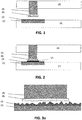
- the kit of parts before contacting and the device after contacting is represented in FIG. 1 and FIG. 2 .
- the interface in the different steps of contacting is represented in FIG. 3a to FIG. 3d .
- the kit of parts comprises a first substrate 1 comprising a conducting material 2 thereon to realize the electrical contact to for example devices included in the substrate.
- a conducting material 2 may be a conducting layer such as a metal layer, but it may also be part of or be conducting material in a via.
- the conducting material 2 according to the method of the invention is Cu.
- Other examples of the conducting material 2 not forming part of the invention can be metals such as Au, Al, Cu, Co, Ni, Pd, alloys of the previous, also other conducting materials, such as conducting polymers and implanted semiconductors can be used.
- multilayers of conducting material, such as Ni/Cu, and Co/Cu, can be used in the method of the invention.
- conducting material such as Ni/Au, Cu/Au and Cu/Al
- the conducting material can for example be bondpads to chip in IC technology.
- the width can for example vary between 80 ⁇ m and 100 ⁇ m.
- first intermetallic layer 3 is realized on top of the conducting material 2 .
- good electrical contact is realized between the first intermetallic layer 3 and the underlying conducting material 2.
- good adhesion between the intermetallic layer and the conducting material is realized.
- the first intermetallic layer 3 may for example be formed by depositing a reactive layer on the metal or the alloy, for example by sputtering or electroplating. An intermetallic layer 3 may then be formed by diffusion of the reactive layer into the conducting layer and vice versa. A heating step can be applied for example to facilitate the interdiffusion of the materials.
- the following combinations are for example possible: In on Au, In on Cu, In on Ni, Sn on Ni, Sn on Co, Sn3.0Ag0.5Cu on Cu, and Cu on Al or, according to the method of the invention, Sn on Cu.
- the first intermetallic layer 3 can also be deposited on the conducting material 2 on the first substrate 1.
- the intermetallic layer 3 can for example be deposited with sputtering.
- one or more intermediate layers between the conducting layer and the intermetallic layer 3 can be provided. The surface treatment and/or extra intermediate layers can for example be added to improve the adhesion (for example as an adhesion layer) or for realizing and/or improving electrical contact between the conducing layer and the first intermetallic layer 3.
- the first intermetallic layer 3 is in a stable phase. This means that it is non-reactive with the underlying conducting layer, such that the thickness is not increasing upon further processing. This is for example the case when a thin Sn layer is deposited on Cu to form the stoechiometric Cu 3 Sn.
- the intermetallic layer 3 is relatively thin.
- the thickness can vary between 500nm and 5000nm, between 700nm and 4000nm, or between 900nm and 3000nm, or between 1000 nm and 2000 nm, or between 1200nm and 1500nm, but other thicknesses are possible depending on the application.
- the first intermetallic layer 3 has a roughness that is higher than the roughness of the solder material that may or will come in contact with the first intermetallic layer 3.
- the RMS roughness of the intermetallic is higher than 0.1 ⁇ m or preferably higher than 0.2 ⁇ m or higher than 0.3 ⁇ m or higher than 0.4 ⁇ m or higher than 0.5 ⁇ m.
- the RMS roughness of the intermetallic can be between 0.1 ⁇ m and 1 ⁇ m, or between 0.2 ⁇ m and 0.5 ⁇ m.
- the maximum height difference or peak-to-valley height difference can be higher than 0.2 ⁇ m or higher than 0.3 ⁇ m or higher than 0.4 ⁇ m or preferably higher than 0.5 ⁇ m, or higher than 0.6 ⁇ m or higher than 0.7 ⁇ m.
- the peak-to-valley height difference can be between 0.2 ⁇ m and 2 ⁇ m or between 0.5 ⁇ m and 1 ⁇ m .
- the solder material 6 will only locally contact the first intermetallic layer 3 due to the fact that the intermetallic layer 3 is very rough, e.g. made by electroplating.
- the first intermetallic layer 3 is brittle, even though the total load applied (for example in flip-chip bonding) is not high, the local pressure is still high enough to break this brittle intermetallic layer.
- a rough surface is thereby advantageous as a high local pressure is created that breaks the brittle intermetallic layer 3.
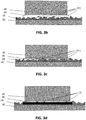
- FIG. 3a and 3b a larger contact area between the solder material 6 and the intermetallic layer 3 is created. This is illustrated in FIG. 3a and 3b . In FIG. 3a to FIG.
- FIG. 3d detailed views are given of the different steps of the solder material contacting the underlying intermetallic layer.
- FIG. 3a there is no contact between the solder material and the intermetallic layer.
- FIG. 3b illustrates the case where the solder material contacts the intermetallic and the intermetallic layer is broken. Upon further contacting, the intermetallic layer can further be broken.
- the intermetallic layer 3 may break when only a percentage of the contacting area of the solder material surface is in contact with the surface of the intermetallic, for example 20% or 30% or 40% or 50% or 60% or 70% or 80% of the contacting area of the solder material surface is in contact with the intermetallic layer 3. So the intermetallic layer 3 can break when the percentage of the contacting area of the solder material surface in contact with the surface of the intermetallic is between 20% and 80%, or between 30% and 70% or between 40% and 60%.
- first conducting material 2 on the first substrate 1 and a second conducting material 5 on the second substrate 4 can be realized between the first intermetallic layer 3 and a solder material 6 on the second conducting material 5.
- solder material 6 realizes good electrical contact with the second conducting material 5. If the second conducting material 5 on the second substrate 4 is well-chosen, this can be used as a solder material and an extra solder material layer 6 is not needed. In an alternative example not forming part of the invention, the second conducting material 5 also fulfils the function of the solder material 6.
- solder material 6 In order to further assist in a good and reliable electrical and mechanical contact between the solder material 6 and the first intermetallic layer 3 on the first substrate 1, some characteristics of the solder material 6 may be advantageous, such as the roughness and the hardness. In view of the interaction between solder material 6 and intermetallic layer 3 upon contact, preferred characteristics of the solder material and the intermetallic layer may be selected as function of each other.
- the roughness of the solder material 6 can be higher or lower than the roughness of the first intermetallic layer 3.
- the roughness of the solder material 6 is lower than the roughness of the first intermetallic layer 3, such that, at an early stage of contacting, the solder material 6 will only locally contact this first intermetallic layer 3.
- the roughness of the first intermetallic layer 3 may be rough as such.
- the intermetallic may be rough due to the fact that the electroplated metal layers are rough. Alternatively a roughening step could be performed.
- the first intermetallic layer is brittle, it will break with little deformation and the local pressure is still high enough to break this brittle intermetallic layer. This is illustrated in FIG. 3b .
- the solder material 6 is softer than the intermetallic material 3 on the conducting material 2, such that the solder material 6 deforms upon further contacting the intermetallic layer 3. That way it can at least partially follow the topography of the broken first intermetallic layer 3. It can at least partially fill the holes in the surface of the intermetallic layer 3.
- it completely fills the holes in the surface, thereby realizing electrical connection over the whole contacting area. This is illustrated in FIG. 3c .
- the contacting area between the solder material 6 and the first intermetallic layer 3 can become large when the first intermetallic layer 3 is broken and the solder material 6 follows the contours of this broken layer. This increases the contacting area between the solder material 6 and the first intermetallic layer 3 and that way non-local electrical connection, i.e. overall good electrical connection, can be realized.
- the solder material 6 forms a second intermetallic 7 with the first intermetallic 3 on the first substrate 1.
- the solder material 6 can diffuse through the intermetallic layer 3 and further react with the underlying conducting material to form a high quality intemetallic joint.
- An extra heating step can be applied to facilitate the formation of the second intermetallic layer 7, preferably below the melting points of the solder material 6, the conducting material 2, 5 and the first intermetallic 3.
- the second intermetallic layer 7 can become relatively thick. As it is brittle, the mechanical stability may be lower. This is no problem in case the first substrate and the second substrate are made of materials with a comparable thermal expansion coefficients. This is for example the case in 3D integration where two silicon chips with the same expansion coefficients are electrically connected to each other.
- the second intermetallic layer 7 is preferably thin such that the contact is mechanically stable. Therefore, the solder material 6 can be chosen to be thin such that it is fully consumed after forming the second intermetallic layer 7. After formation, the second intermetallic layer 7 is preferably in a stable phase, such that it may react with the first intermetallic 3 and underlying metal 2 during formation but that the reaction stops thereafter. The second intermetallic layer 7 thus can be relatively thin. This improves the mechanically stability of the connection.
- solder/base material combinations are electroplated Sn in combination with Cu, as in the method of the invention, or electroplated In in combination with Au serving as the solder material and base metal, respectively.
- a brittle CuSn or Auln first intermetallic layer with a certain thickness can be formed on top of the base layer of Cu or Au on one chip.
- a thick Sn / In layer can be deposited as a solder material on the other chip.
- a wet cleaning process step can be incorporated on the solder material before the bonding process to reduce its oxidation, which impedes the efficiency of low-T bonding.
- Certain embodiments allow realizing electrical contact between conducting regions on different substrates at low temperatures. These low temperatures are favourable in various applications, especially when the materials used on the substrates cannot withstand high temperatures.
- the method of the invention may be especially suitable for flip-chip bonding of semiconductor chips, although the invention is not limited. Further method steps optionally also may be comprised in the method of the invention, expressing the functionality of components as described for the devices.
- a silicon wafer with high density memory cells, Cu back-end-of-line, and through-silicon-via (TSV) Cu interconnect is provided that can be used in 3D stacking.
- the Cu/Sn combination can for example be used in 3D integration where dies are stacked on top of each other and electrical connection between the Cu back-end-of-line of the two dies is realized using Sn as a solder material.
- Sn as a solder material.
- low-k materials are used for capacitance reduction. These low-k materials often cannot withstand high pressures.
- advanced DRAM devices are very sensitive to exposure to higher temperatures, and bonding needs to be done at low temperatures.
- One embodiment allows realizing electrical contact between the dies at temperatures well below the temperatures that may damage the memory cells.
- This example does not form part of the present invention.
- following was prepared to bond two chips at low temperature and pressure.
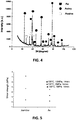
- a thick In solder material bump of about 7 ⁇ m was deposited on one chip by electroplating, and a thin (of 1 ⁇ m thickness) In layer was deposited on another chip that contains a thick Au layer.
- the thin In layer reacted with the thick Au layer to form an Auln intermetallics layer. This was confirmed by XRD (see FIG. 4 ), where many reflection peaks of Auln intermetallic compounds can be distinguished.
- these two chips were placed face-to-face and bonded at 130°C with a pressure of 1, 2 and 10 MPa for 14 minutes, respectively. After bonding, the cross-section of the bonded interface was studied by scanning electron microscopy, and also the shear test is carried out in order to investigate the bonding quality.
- Cu to Sn bonding follows the similar procedure as Au to In bonding.
- a thick Sn of about 5 ⁇ m solder material bump was deposited on one chip by electroplating, and a thin Sn layer was deposited on another chip that contains a thick Cu layer. Since the peak-to-valley roughness (h t ) of the electroplated Sn was between 0.5-1.0 ⁇ m, a 1.5 ⁇ m-thick Sn layer is deposited on Cu so that the Cu is fully covered by Sn.
- the thin Sn layer reacts with the thick Cu layer to form CuSn intermetallics. Since the growth rate of CuSn intemetallic is lower than that of Auln intermetallics, the chip was heated up to 100°C in order to accelerate the Cu/Sn reaction.
- the excess Sn on this chip was removed by an HCl etch to guarantee that Cu is bonded to Sn (on the other chip) through the CuSn intemetallics. Then these two chips were placed face-to-face, and were bonded at 150°C and 200°C with a pressure of 2 and 10 MPa for 14 minutes, respectively. Finally, the shear strength is measured by shear test. As shown in FIG. 6a and FIG. 6b , the shear strength of Cu bonded to Sn with an intermetallic layer (after etching away the excess Sn) was higher than that of without this intermetallic layer. This was consistent with what was observed in the Au/In system.
Landscapes
- Wire Bonding (AREA)
Applications Claiming Priority (2)
| Application Number | Priority Date | Filing Date | Title |
|---|---|---|---|
| US9819408P | 2008-09-18 | 2008-09-18 | |
| PCT/EP2009/062125 WO2010031845A1 (en) | 2008-09-18 | 2009-09-18 | Methods and systems for material bonding |
Publications (2)
| Publication Number | Publication Date |
|---|---|
| EP2340554A1 EP2340554A1 (en) | 2011-07-06 |
| EP2340554B1 true EP2340554B1 (en) | 2017-05-10 |
Family
ID=41268461
Family Applications (1)
| Application Number | Title | Priority Date | Filing Date |
|---|---|---|---|
| EP09783180.4A Active EP2340554B1 (en) | 2008-09-18 | 2009-09-18 | Methods and systems for material bonding |
Country Status (4)
| Country | Link |
|---|---|
| US (1) | US8536047B2 (enExample) |
| EP (1) | EP2340554B1 (enExample) |
| JP (1) | JP5438114B2 (enExample) |
| WO (1) | WO2010031845A1 (enExample) |
Families Citing this family (15)
| Publication number | Priority date | Publication date | Assignee | Title |
|---|---|---|---|---|
| EP2363373A1 (en) * | 2010-03-02 | 2011-09-07 | SensoNor Technologies AS | Bonding process for sensitive micro-and nano-systems |
| EP2597670B1 (de) | 2010-03-31 | 2016-03-30 | EV Group E. Thallner GmbH | Verfahren zum permanenten Verbinden zweier Metalloberflächen |
| US8802553B2 (en) * | 2011-02-10 | 2014-08-12 | Infineon Technologies Ag | Method for mounting a semiconductor chip on a carrier |
| JP5588419B2 (ja) | 2011-10-26 | 2014-09-10 | 株式会社東芝 | パッケージ |
| US8916448B2 (en) | 2013-01-09 | 2014-12-23 | International Business Machines Corporation | Metal to metal bonding for stacked (3D) integrated circuits |
| US9802360B2 (en) | 2013-06-04 | 2017-10-31 | Stratsys, Inc. | Platen planarizing process for additive manufacturing system |
| DE102014116030A1 (de) * | 2014-11-04 | 2016-05-04 | Infineon Technologies Ag | Verfahren zur Herstellung einer Verbindung und Anordnung für eine Chipzusammenstellung mit Direktverbindung |
| CN105826243A (zh) * | 2015-01-09 | 2016-08-03 | 中芯国际集成电路制造(上海)有限公司 | 晶圆键合方法以及晶圆键合结构 |
| US9620434B1 (en) | 2016-03-07 | 2017-04-11 | Toyota Motor Engineering & Manufacturing North America, Inc. | High temperature bonding processes incorporating metal particles and bonded substrates formed therefrom |
| JP2017204599A (ja) * | 2016-05-13 | 2017-11-16 | 日本電気硝子株式会社 | 気密パッケージの製造方法及び気密パッケージ |
| EP3754706A1 (en) | 2019-06-20 | 2020-12-23 | IMEC vzw | A method for the electrical bonding of semiconductor components |
| US11164845B2 (en) | 2020-01-30 | 2021-11-02 | International Business Machines Corporation | Resist structure for forming bumps |
| JP7590931B2 (ja) * | 2021-06-16 | 2024-11-27 | ルネサスエレクトロニクス株式会社 | 半導体装置 |
| US20230036201A1 (en) * | 2021-07-30 | 2023-02-02 | Stmicroelectronics, Inc. | Leadless semiconductor package with de-metallized porous structures and method for manufacturing the same |
| US20250140657A1 (en) * | 2023-10-27 | 2025-05-01 | Ideal Semiconductor Devices, Inc. | Semiconductor device and method of fabricating same |
Family Cites Families (26)
| Publication number | Priority date | Publication date | Assignee | Title |
|---|---|---|---|---|
| US292824A (en) * | 1884-02-05 | Stop and waste cock | ||
| US27294A (en) * | 1860-02-28 | Henry isham | ||
| US114662A (en) * | 1871-05-09 | Improvement in iron culverts | ||
| US3839727A (en) * | 1973-06-25 | 1974-10-01 | Ibm | Semiconductor chip to substrate solder bond using a locally dispersed, ternary intermetallic compound |
| US5551627A (en) * | 1994-09-29 | 1996-09-03 | Motorola, Inc. | Alloy solder connect assembly and method of connection |
| US6342442B1 (en) * | 1998-11-20 | 2002-01-29 | Agere Systems Guardian Corp. | Kinetically controlled solder bonding |
| WO2001086715A2 (de) * | 2000-05-05 | 2001-11-15 | Infineon Technologies Ag | Verfahren zum verlöten einer ersten metallschicht, die eine dicke von weniger als 5 $g(m)m aufweist, mit einer zweiten metallschicht, löteinrichtung und halbleiterchip-montagevorrichtung |
| US6492197B1 (en) * | 2000-05-23 | 2002-12-10 | Unitive Electronics Inc. | Trilayer/bilayer solder bumps and fabrication methods therefor |
| US20020027294A1 (en) | 2000-07-21 | 2002-03-07 | Neuhaus Herbert J. | Electrical component assembly and method of fabrication |
| JP4656275B2 (ja) * | 2001-01-15 | 2011-03-23 | 日本電気株式会社 | 半導体装置の製造方法 |
| JP3897596B2 (ja) * | 2002-01-07 | 2007-03-28 | 日本テキサス・インスツルメンツ株式会社 | 半導体装置と配線基板との実装体 |
| US6926955B2 (en) * | 2002-02-08 | 2005-08-09 | Intel Corporation | Phase change material containing fusible particles as thermally conductive filler |
| US6793829B2 (en) * | 2002-02-27 | 2004-09-21 | Honeywell International Inc. | Bonding for a micro-electro-mechanical system (MEMS) and MEMS based devices |
| JP4034107B2 (ja) * | 2002-04-17 | 2008-01-16 | 株式会社ルネサステクノロジ | 半導体装置 |
| JP3682654B2 (ja) * | 2002-09-25 | 2005-08-10 | 千住金属工業株式会社 | 無電解Niメッキ部分へのはんだ付け用はんだ合金 |
| US20050067699A1 (en) * | 2003-09-29 | 2005-03-31 | Intel Corporation | Diffusion barrier layer for lead free package substrate |
| US6994920B2 (en) * | 2003-10-31 | 2006-02-07 | General Electric Company | Fusion welding method and welded article |
| US7064446B2 (en) * | 2004-03-29 | 2006-06-20 | Intel Corporation | Under bump metallization layer to enable use of high tin content solder bumps |
| US7148569B1 (en) * | 2004-09-07 | 2006-12-12 | Altera Corporation | Pad surface finish for high routing density substrate of BGA packages |
| EP1732116B1 (en) * | 2005-06-08 | 2017-02-01 | Imec | Methods for bonding and micro-electronic devices produced according to such methods |
| JP4569423B2 (ja) * | 2005-08-31 | 2010-10-27 | 株式会社日立製作所 | 半導体装置の製造方法 |
| DE102005055280B3 (de) * | 2005-11-17 | 2007-04-12 | Infineon Technologies Ag | Verbindungselement zwischen Halbleiterchip und Schaltungsträger sowie Verfahren zur Herstellung und Verwendung des Verbindungselements |
| US7626274B2 (en) * | 2006-02-03 | 2009-12-01 | Texas Instruments Incorporated | Semiconductor device with an improved solder joint |
| US7939939B1 (en) * | 2007-06-11 | 2011-05-10 | Texas Instruments Incorporated | Stable gold bump solder connections |
| CN103299406A (zh) * | 2007-09-21 | 2013-09-11 | 艾格瑞系统有限公司 | 用于改善耐脆性断裂的焊接方法及相关器件 |
| JP5535448B2 (ja) * | 2008-05-19 | 2014-07-02 | シャープ株式会社 | 半導体装置、半導体装置の実装方法、および半導体装置の実装構造 |
-
2009
- 2009-09-18 EP EP09783180.4A patent/EP2340554B1/en active Active
- 2009-09-18 WO PCT/EP2009/062125 patent/WO2010031845A1/en not_active Ceased
- 2009-09-18 JP JP2011527336A patent/JP5438114B2/ja active Active
-
2011
- 2011-03-18 US US13/051,357 patent/US8536047B2/en active Active
Also Published As
| Publication number | Publication date |
|---|---|
| JP5438114B2 (ja) | 2014-03-12 |
| US20110233792A1 (en) | 2011-09-29 |
| WO2010031845A1 (en) | 2010-03-25 |
| JP2012503321A (ja) | 2012-02-02 |
| EP2340554A1 (en) | 2011-07-06 |
| US8536047B2 (en) | 2013-09-17 |
Similar Documents
| Publication | Publication Date | Title |
|---|---|---|
| EP2340554B1 (en) | Methods and systems for material bonding | |
| EP1732116B1 (en) | Methods for bonding and micro-electronic devices produced according to such methods | |
| US6962835B2 (en) | Method for room temperature metal direct bonding | |
| US6583514B2 (en) | Semiconductor device with a binary alloy bonding layer | |
| US10354975B2 (en) | Barrier layer for interconnects in 3D integrated device | |
| US7642135B2 (en) | Thermal mechanical flip chip die bonding | |
| US6667225B2 (en) | Wafer-bonding using solder and method of making the same | |
| US7015580B2 (en) | Roughened bonding pad and bonding wire surfaces for low pressure wire bonding | |
| US20140035167A1 (en) | Method for producing a bonding pad for thermocompression bonding, and bonding pad | |
| US7993971B2 (en) | Forming a 3-D semiconductor die structure with an intermetallic formation | |
| US20050170609A1 (en) | Conductive bond for through-wafer interconnect | |
| Choi et al. | Development of novel intermetallic joints using thin film indium based solder by low temperature bonding technology for 3D IC stacking | |
| US20040154165A1 (en) | Method for manufacturing a probe pin and a probe card | |
| CN119340299A (zh) | 一种半导体器件结构及其制备方法和相应芯片 | |
| JP7705209B2 (ja) | ファンアウトパッケージまたは相互接続ブリッジのための転写可能ピラー構造 | |
| Garnier et al. | Investigation of copper-tin transient liquid phase bonding reliability for 3D integration | |
| Hungar et al. | Gold/tin soldering of flexible silicon chips onto polymer tapes | |
| Ang et al. | Direct metal to metal bonding for microsystems interconnections and integration | |
| Dragoi et al. | Wafer bonding for MEMS and CMOS integration | |
| Ang et al. | Studies of Temperature and Pressure Dependence in Thermocompression Gold Joints |
Legal Events
| Date | Code | Title | Description |
|---|---|---|---|
| PUAI | Public reference made under article 153(3) epc to a published international application that has entered the european phase |
Free format text: ORIGINAL CODE: 0009012 |
|
| 17P | Request for examination filed |
Effective date: 20110415 |
|
| AK | Designated contracting states |
Kind code of ref document: A1 Designated state(s): AT BE BG CH CY CZ DE DK EE ES FI FR GB GR HR HU IE IS IT LI LT LU LV MC MK MT NL NO PL PT RO SE SI SK SM TR |
|
| AX | Request for extension of the european patent |
Extension state: AL BA RS |
|
| DAX | Request for extension of the european patent (deleted) | ||
| 17Q | First examination report despatched |
Effective date: 20150316 |
|
| GRAP | Despatch of communication of intention to grant a patent |
Free format text: ORIGINAL CODE: EPIDOSNIGR1 |
|
| INTG | Intention to grant announced |
Effective date: 20161123 |
|
| GRAS | Grant fee paid |
Free format text: ORIGINAL CODE: EPIDOSNIGR3 |
|
| GRAA | (expected) grant |
Free format text: ORIGINAL CODE: 0009210 |
|
| AK | Designated contracting states |
Kind code of ref document: B1 Designated state(s): AT BE BG CH CY CZ DE DK EE ES FI FR GB GR HR HU IE IS IT LI LT LU LV MC MK MT NL NO PL PT RO SE SI SK SM TR |
|
| REG | Reference to a national code |
Ref country code: GB Ref legal event code: FG4D |
|
| REG | Reference to a national code |
Ref country code: AT Ref legal event code: REF Ref document number: 893143 Country of ref document: AT Kind code of ref document: T Effective date: 20170515 Ref country code: CH Ref legal event code: EP |
|
| REG | Reference to a national code |
Ref country code: IE Ref legal event code: FG4D |
|
| REG | Reference to a national code |
Ref country code: DE Ref legal event code: R096 Ref document number: 602009046025 Country of ref document: DE |
|
| REG | Reference to a national code |
Ref country code: FR Ref legal event code: PLFP Year of fee payment: 9 |
|
| REG | Reference to a national code |
Ref country code: NL Ref legal event code: MP Effective date: 20170510 |
|
| REG | Reference to a national code |
Ref country code: LT Ref legal event code: MG4D |
|
| REG | Reference to a national code |
Ref country code: AT Ref legal event code: MK05 Ref document number: 893143 Country of ref document: AT Kind code of ref document: T Effective date: 20170510 |
|
| PG25 | Lapsed in a contracting state [announced via postgrant information from national office to epo] |
Ref country code: FI Free format text: LAPSE BECAUSE OF FAILURE TO SUBMIT A TRANSLATION OF THE DESCRIPTION OR TO PAY THE FEE WITHIN THE PRESCRIBED TIME-LIMIT Effective date: 20170510 Ref country code: GR Free format text: LAPSE BECAUSE OF FAILURE TO SUBMIT A TRANSLATION OF THE DESCRIPTION OR TO PAY THE FEE WITHIN THE PRESCRIBED TIME-LIMIT Effective date: 20170811 Ref country code: ES Free format text: LAPSE BECAUSE OF FAILURE TO SUBMIT A TRANSLATION OF THE DESCRIPTION OR TO PAY THE FEE WITHIN THE PRESCRIBED TIME-LIMIT Effective date: 20170510 Ref country code: NO Free format text: LAPSE BECAUSE OF FAILURE TO SUBMIT A TRANSLATION OF THE DESCRIPTION OR TO PAY THE FEE WITHIN THE PRESCRIBED TIME-LIMIT Effective date: 20170810 Ref country code: LT Free format text: LAPSE BECAUSE OF FAILURE TO SUBMIT A TRANSLATION OF THE DESCRIPTION OR TO PAY THE FEE WITHIN THE PRESCRIBED TIME-LIMIT Effective date: 20170510 Ref country code: AT Free format text: LAPSE BECAUSE OF FAILURE TO SUBMIT A TRANSLATION OF THE DESCRIPTION OR TO PAY THE FEE WITHIN THE PRESCRIBED TIME-LIMIT Effective date: 20170510 Ref country code: HR Free format text: LAPSE BECAUSE OF FAILURE TO SUBMIT A TRANSLATION OF THE DESCRIPTION OR TO PAY THE FEE WITHIN THE PRESCRIBED TIME-LIMIT Effective date: 20170510 |
|
| PG25 | Lapsed in a contracting state [announced via postgrant information from national office to epo] |
Ref country code: PL Free format text: LAPSE BECAUSE OF FAILURE TO SUBMIT A TRANSLATION OF THE DESCRIPTION OR TO PAY THE FEE WITHIN THE PRESCRIBED TIME-LIMIT Effective date: 20170510 Ref country code: BG Free format text: LAPSE BECAUSE OF FAILURE TO SUBMIT A TRANSLATION OF THE DESCRIPTION OR TO PAY THE FEE WITHIN THE PRESCRIBED TIME-LIMIT Effective date: 20170810 Ref country code: IS Free format text: LAPSE BECAUSE OF FAILURE TO SUBMIT A TRANSLATION OF THE DESCRIPTION OR TO PAY THE FEE WITHIN THE PRESCRIBED TIME-LIMIT Effective date: 20170910 Ref country code: LV Free format text: LAPSE BECAUSE OF FAILURE TO SUBMIT A TRANSLATION OF THE DESCRIPTION OR TO PAY THE FEE WITHIN THE PRESCRIBED TIME-LIMIT Effective date: 20170510 Ref country code: NL Free format text: LAPSE BECAUSE OF FAILURE TO SUBMIT A TRANSLATION OF THE DESCRIPTION OR TO PAY THE FEE WITHIN THE PRESCRIBED TIME-LIMIT Effective date: 20170510 Ref country code: SE Free format text: LAPSE BECAUSE OF FAILURE TO SUBMIT A TRANSLATION OF THE DESCRIPTION OR TO PAY THE FEE WITHIN THE PRESCRIBED TIME-LIMIT Effective date: 20170510 |
|
| RAP2 | Party data changed (patent owner data changed or rights of a patent transferred) |
Owner name: IMEC VZW |
|
| PG25 | Lapsed in a contracting state [announced via postgrant information from national office to epo] |
Ref country code: SK Free format text: LAPSE BECAUSE OF FAILURE TO SUBMIT A TRANSLATION OF THE DESCRIPTION OR TO PAY THE FEE WITHIN THE PRESCRIBED TIME-LIMIT Effective date: 20170510 Ref country code: CZ Free format text: LAPSE BECAUSE OF FAILURE TO SUBMIT A TRANSLATION OF THE DESCRIPTION OR TO PAY THE FEE WITHIN THE PRESCRIBED TIME-LIMIT Effective date: 20170510 Ref country code: DK Free format text: LAPSE BECAUSE OF FAILURE TO SUBMIT A TRANSLATION OF THE DESCRIPTION OR TO PAY THE FEE WITHIN THE PRESCRIBED TIME-LIMIT Effective date: 20170510 Ref country code: EE Free format text: LAPSE BECAUSE OF FAILURE TO SUBMIT A TRANSLATION OF THE DESCRIPTION OR TO PAY THE FEE WITHIN THE PRESCRIBED TIME-LIMIT Effective date: 20170510 Ref country code: RO Free format text: LAPSE BECAUSE OF FAILURE TO SUBMIT A TRANSLATION OF THE DESCRIPTION OR TO PAY THE FEE WITHIN THE PRESCRIBED TIME-LIMIT Effective date: 20170510 |
|
| REG | Reference to a national code |
Ref country code: DE Ref legal event code: R097 Ref document number: 602009046025 Country of ref document: DE |
|
| PG25 | Lapsed in a contracting state [announced via postgrant information from national office to epo] |
Ref country code: SM Free format text: LAPSE BECAUSE OF FAILURE TO SUBMIT A TRANSLATION OF THE DESCRIPTION OR TO PAY THE FEE WITHIN THE PRESCRIBED TIME-LIMIT Effective date: 20170510 Ref country code: IT Free format text: LAPSE BECAUSE OF FAILURE TO SUBMIT A TRANSLATION OF THE DESCRIPTION OR TO PAY THE FEE WITHIN THE PRESCRIBED TIME-LIMIT Effective date: 20170510 |
|
| PLBE | No opposition filed within time limit |
Free format text: ORIGINAL CODE: 0009261 |
|
| STAA | Information on the status of an ep patent application or granted ep patent |
Free format text: STATUS: NO OPPOSITION FILED WITHIN TIME LIMIT |
|
| 26N | No opposition filed |
Effective date: 20180213 |
|
| REG | Reference to a national code |
Ref country code: CH Ref legal event code: PL |
|
| GBPC | Gb: european patent ceased through non-payment of renewal fee |
Effective date: 20170918 |
|
| PG25 | Lapsed in a contracting state [announced via postgrant information from national office to epo] |
Ref country code: MC Free format text: LAPSE BECAUSE OF FAILURE TO SUBMIT A TRANSLATION OF THE DESCRIPTION OR TO PAY THE FEE WITHIN THE PRESCRIBED TIME-LIMIT Effective date: 20170510 Ref country code: SI Free format text: LAPSE BECAUSE OF FAILURE TO SUBMIT A TRANSLATION OF THE DESCRIPTION OR TO PAY THE FEE WITHIN THE PRESCRIBED TIME-LIMIT Effective date: 20170510 |
|
| REG | Reference to a national code |
Ref country code: IE Ref legal event code: MM4A |
|
| REG | Reference to a national code |
Ref country code: BE Ref legal event code: MM Effective date: 20170930 |
|
| PG25 | Lapsed in a contracting state [announced via postgrant information from national office to epo] |
Ref country code: LU Free format text: LAPSE BECAUSE OF NON-PAYMENT OF DUE FEES Effective date: 20170918 |
|
| PG25 | Lapsed in a contracting state [announced via postgrant information from national office to epo] |
Ref country code: CH Free format text: LAPSE BECAUSE OF NON-PAYMENT OF DUE FEES Effective date: 20170930 Ref country code: LI Free format text: LAPSE BECAUSE OF NON-PAYMENT OF DUE FEES Effective date: 20170930 Ref country code: IE Free format text: LAPSE BECAUSE OF NON-PAYMENT OF DUE FEES Effective date: 20170918 Ref country code: GB Free format text: LAPSE BECAUSE OF NON-PAYMENT OF DUE FEES Effective date: 20170918 |
|
| REG | Reference to a national code |
Ref country code: FR Ref legal event code: PLFP Year of fee payment: 10 |
|
| PG25 | Lapsed in a contracting state [announced via postgrant information from national office to epo] |
Ref country code: BE Free format text: LAPSE BECAUSE OF NON-PAYMENT OF DUE FEES Effective date: 20170930 |
|
| PG25 | Lapsed in a contracting state [announced via postgrant information from national office to epo] |
Ref country code: MT Free format text: LAPSE BECAUSE OF NON-PAYMENT OF DUE FEES Effective date: 20170918 |
|
| PG25 | Lapsed in a contracting state [announced via postgrant information from national office to epo] |
Ref country code: HU Free format text: LAPSE BECAUSE OF FAILURE TO SUBMIT A TRANSLATION OF THE DESCRIPTION OR TO PAY THE FEE WITHIN THE PRESCRIBED TIME-LIMIT; INVALID AB INITIO Effective date: 20090918 |
|
| PG25 | Lapsed in a contracting state [announced via postgrant information from national office to epo] |
Ref country code: CY Free format text: LAPSE BECAUSE OF NON-PAYMENT OF DUE FEES Effective date: 20170510 |
|
| PG25 | Lapsed in a contracting state [announced via postgrant information from national office to epo] |
Ref country code: MK Free format text: LAPSE BECAUSE OF FAILURE TO SUBMIT A TRANSLATION OF THE DESCRIPTION OR TO PAY THE FEE WITHIN THE PRESCRIBED TIME-LIMIT Effective date: 20170510 |
|
| PG25 | Lapsed in a contracting state [announced via postgrant information from national office to epo] |
Ref country code: TR Free format text: LAPSE BECAUSE OF FAILURE TO SUBMIT A TRANSLATION OF THE DESCRIPTION OR TO PAY THE FEE WITHIN THE PRESCRIBED TIME-LIMIT Effective date: 20170510 |
|
| PG25 | Lapsed in a contracting state [announced via postgrant information from national office to epo] |
Ref country code: PT Free format text: LAPSE BECAUSE OF FAILURE TO SUBMIT A TRANSLATION OF THE DESCRIPTION OR TO PAY THE FEE WITHIN THE PRESCRIBED TIME-LIMIT Effective date: 20170510 |
|
| P01 | Opt-out of the competence of the unified patent court (upc) registered |
Effective date: 20230513 |
|
| PGFP | Annual fee paid to national office [announced via postgrant information from national office to epo] |
Ref country code: DE Payment date: 20250820 Year of fee payment: 17 |
|
| PGFP | Annual fee paid to national office [announced via postgrant information from national office to epo] |
Ref country code: FR Payment date: 20250820 Year of fee payment: 17 |
|
| REG | Reference to a national code |
Ref country code: DE Ref legal event code: R079 Ref document number: 602009046025 Country of ref document: DE Free format text: PREVIOUS MAIN CLASS: H01L0021600000 Ipc: H10W0070010000 |