EP2339419A1 - Maximierung des Ausbeute von Artikeln aus Bahnen-Materialien - Google Patents
Maximierung des Ausbeute von Artikeln aus Bahnen-Materialien Download PDFInfo
- Publication number
- EP2339419A1 EP2339419A1 EP11157019A EP11157019A EP2339419A1 EP 2339419 A1 EP2339419 A1 EP 2339419A1 EP 11157019 A EP11157019 A EP 11157019A EP 11157019 A EP11157019 A EP 11157019A EP 2339419 A1 EP2339419 A1 EP 2339419A1
- Authority
- EP
- European Patent Office
- Prior art keywords
- web
- conversion
- products
- conversion control
- product
- Prior art date
- Legal status (The legal status is an assumption and is not a legal conclusion. Google has not performed a legal analysis and makes no representation as to the accuracy of the status listed.)
- Withdrawn
Links
Images


Classifications
-
- G—PHYSICS
- G01—MEASURING; TESTING
- G01N—INVESTIGATING OR ANALYSING MATERIALS BY DETERMINING THEIR CHEMICAL OR PHYSICAL PROPERTIES
- G01N21/00—Investigating or analysing materials by the use of optical means, i.e. using sub-millimetre waves, infrared, visible or ultraviolet light
- G01N21/84—Systems specially adapted for particular applications
- G01N21/88—Investigating the presence of flaws or contamination
- G01N21/89—Investigating the presence of flaws or contamination in moving material, e.g. running paper or textiles
-
- G—PHYSICS
- G06—COMPUTING; CALCULATING OR COUNTING
- G06Q—INFORMATION AND COMMUNICATION TECHNOLOGY [ICT] SPECIALLY ADAPTED FOR ADMINISTRATIVE, COMMERCIAL, FINANCIAL, MANAGERIAL OR SUPERVISORY PURPOSES; SYSTEMS OR METHODS SPECIALLY ADAPTED FOR ADMINISTRATIVE, COMMERCIAL, FINANCIAL, MANAGERIAL OR SUPERVISORY PURPOSES, NOT OTHERWISE PROVIDED FOR
- G06Q50/00—Systems or methods specially adapted for specific business sectors, e.g. utilities or tourism
- G06Q50/04—Manufacturing
-
- G—PHYSICS
- G05—CONTROLLING; REGULATING
- G05B—CONTROL OR REGULATING SYSTEMS IN GENERAL; FUNCTIONAL ELEMENTS OF SUCH SYSTEMS; MONITORING OR TESTING ARRANGEMENTS FOR SUCH SYSTEMS OR ELEMENTS
- G05B19/00—Programme-control systems
- G05B19/02—Programme-control systems electric
- G05B19/418—Total factory control, i.e. centrally controlling a plurality of machines, e.g. direct or distributed numerical control [DNC], flexible manufacturing systems [FMS], integrated manufacturing systems [IMS], computer integrated manufacturing [CIM]
- G05B19/41865—Total factory control, i.e. centrally controlling a plurality of machines, e.g. direct or distributed numerical control [DNC], flexible manufacturing systems [FMS], integrated manufacturing systems [IMS], computer integrated manufacturing [CIM] characterised by job scheduling, process planning, material flow
-
- G—PHYSICS
- G06—COMPUTING; CALCULATING OR COUNTING
- G06T—IMAGE DATA PROCESSING OR GENERATION, IN GENERAL
- G06T7/00—Image analysis
- G06T7/0002—Inspection of images, e.g. flaw detection
- G06T7/0004—Industrial image inspection
-
- G—PHYSICS
- G01—MEASURING; TESTING
- G01N—INVESTIGATING OR ANALYSING MATERIALS BY DETERMINING THEIR CHEMICAL OR PHYSICAL PROPERTIES
- G01N21/00—Investigating or analysing materials by the use of optical means, i.e. using sub-millimetre waves, infrared, visible or ultraviolet light
- G01N21/84—Systems specially adapted for particular applications
- G01N21/88—Investigating the presence of flaws or contamination
- G01N21/8851—Scan or image signal processing specially adapted therefor, e.g. for scan signal adjustment, for detecting different kinds of defects, for compensating for structures, markings, edges
- G01N2021/8854—Grading and classifying of flaws
-
- G—PHYSICS
- G05—CONTROLLING; REGULATING
- G05B—CONTROL OR REGULATING SYSTEMS IN GENERAL; FUNCTIONAL ELEMENTS OF SUCH SYSTEMS; MONITORING OR TESTING ARRANGEMENTS FOR SUCH SYSTEMS OR ELEMENTS
- G05B2219/00—Program-control systems
- G05B2219/30—Nc systems
- G05B2219/32—Operator till task planning
- G05B2219/32036—Enter data, values for custom made articles
-
- G—PHYSICS
- G05—CONTROLLING; REGULATING
- G05B—CONTROL OR REGULATING SYSTEMS IN GENERAL; FUNCTIONAL ELEMENTS OF SUCH SYSTEMS; MONITORING OR TESTING ARRANGEMENTS FOR SUCH SYSTEMS OR ELEMENTS
- G05B2219/00—Program-control systems
- G05B2219/30—Nc systems
- G05B2219/32—Operator till task planning
- G05B2219/32304—Minimize flow time, tact, shortest processing, machining time
-
- G—PHYSICS
- G05—CONTROLLING; REGULATING
- G05B—CONTROL OR REGULATING SYSTEMS IN GENERAL; FUNCTIONAL ELEMENTS OF SUCH SYSTEMS; MONITORING OR TESTING ARRANGEMENTS FOR SUCH SYSTEMS OR ELEMENTS
- G05B2219/00—Program-control systems
- G05B2219/30—Nc systems
- G05B2219/32—Operator till task planning
- G05B2219/32318—Smallest value of product of imminent processing time with total processing time
-
- G—PHYSICS
- G05—CONTROLLING; REGULATING
- G05B—CONTROL OR REGULATING SYSTEMS IN GENERAL; FUNCTIONAL ELEMENTS OF SUCH SYSTEMS; MONITORING OR TESTING ARRANGEMENTS FOR SUCH SYSTEMS OR ELEMENTS
- G05B2219/00—Program-control systems
- G05B2219/30—Nc systems
- G05B2219/45—Nc applications
- G05B2219/45234—Thin flat workpiece, sheet metal machining
-
- G—PHYSICS
- G06—COMPUTING; CALCULATING OR COUNTING
- G06T—IMAGE DATA PROCESSING OR GENERATION, IN GENERAL
- G06T2207/00—Indexing scheme for image analysis or image enhancement
- G06T2207/30—Subject of image; Context of image processing
- G06T2207/30108—Industrial image inspection
- G06T2207/30124—Fabrics; Textile; Paper
-
- Y—GENERAL TAGGING OF NEW TECHNOLOGICAL DEVELOPMENTS; GENERAL TAGGING OF CROSS-SECTIONAL TECHNOLOGIES SPANNING OVER SEVERAL SECTIONS OF THE IPC; TECHNICAL SUBJECTS COVERED BY FORMER USPC CROSS-REFERENCE ART COLLECTIONS [XRACs] AND DIGESTS
- Y02—TECHNOLOGIES OR APPLICATIONS FOR MITIGATION OR ADAPTATION AGAINST CLIMATE CHANGE
- Y02P—CLIMATE CHANGE MITIGATION TECHNOLOGIES IN THE PRODUCTION OR PROCESSING OF GOODS
- Y02P90/00—Enabling technologies with a potential contribution to greenhouse gas [GHG] emissions mitigation
- Y02P90/02—Total factory control, e.g. smart factories, flexible manufacturing systems [FMS] or integrated manufacturing systems [IMS]
-
- Y—GENERAL TAGGING OF NEW TECHNOLOGICAL DEVELOPMENTS; GENERAL TAGGING OF CROSS-SECTIONAL TECHNOLOGIES SPANNING OVER SEVERAL SECTIONS OF THE IPC; TECHNICAL SUBJECTS COVERED BY FORMER USPC CROSS-REFERENCE ART COLLECTIONS [XRACs] AND DIGESTS
- Y02—TECHNOLOGIES OR APPLICATIONS FOR MITIGATION OR ADAPTATION AGAINST CLIMATE CHANGE
- Y02P—CLIMATE CHANGE MITIGATION TECHNOLOGIES IN THE PRODUCTION OR PROCESSING OF GOODS
- Y02P90/00—Enabling technologies with a potential contribution to greenhouse gas [GHG] emissions mitigation
- Y02P90/80—Management or planning
Definitions
- the present invention relates to automated inspection of systems, and more particularly, to optical inspection of webs.
- Inspection systems for the analysis of moving web materials have proven critical to modem manufacturing operations.
- Industries as varied as metal fabrication, paper, non-wovens, and films rely on these inspection systems for both product certification and online process monitoring.
- One major difficulty in the industry is related to the extremely high data processing rates required to keep up with current manufacturing processes.
- data acquisition speeds of tens or even hundreds of megabytes per second are required of the inspection systems. It is a continual challenge to process images and perform accurate defect detection at these data rates.
- the difficulty is that during the time of manufacture, it is not known which quality level will be required. Therefore, the current art attempts to grade quality level after defect detection by using various defect classification techniques based on spatial features of the extracted defects. While this is sometimes adequate when gross differences exist between defect levels for different quality requirements, it is not adequate for more demanding situations in which more subtle differences between defects require different image processing and defect extraction algorithms. Thus, if one waits until after defect extraction for classification, information is lost and the classification is impossible.
- the invention is directed to techniques for the automated inspection of moving webs.
- An inspection system acquires anomaly information for a web using an optical acquisition device, and performs a preliminary examination with a first, typically less sophisticated algorithm.
- Image information about the regions of the web containing anomalies is stored for subsequent processing, accepting the likelihood that although some of the anomalies will be defective, many could be "false positives," i.e., anomalies that are not defective.
- some anomaly areas may be ultimately classified as defective if the web is used in a particular product application, but not defective if the web is used in another.
- the original anomaly information can be reconsidered and fully analyzed at a convenient time, even after the inspected web has been wound onto a roll and is unavailable. As a result, the speed of the moving web during the inspection can be much greater than is possible when the entire surface of the web is subjected to a sophisticated analysis.
- conversion decisions can be made offline, and can be based on many factors.
- a conversion control system subsequently reconsiders the original image information, and subjects the image information to at least one of a variety of more sophisticated image processing and defect extraction algorithms to effectively separate actual defects from anomalies.
- the conversion control system utilizes the defect information to control the manner in which a web is ultimately converted to the products based on one or more product selection parameters.
- the conversion control system applies the image processing and defect extraction algorithms to generate defect information for a number of potential web-based products, i.e., products into which the web could be converted.
- the conversion control system identifies which product best achieves the selected parameters, such as a maximum utilization of the web.
- product selection parameters include unit product produced, estimated revenue or profit from the produced product, process time required to convert the web, current machine capacity for each process line, current demand for the different products or other parameters.
- a method comprises imaging a sequential portion of a web to provide digital information, and processing the digital information with at least one initial algorithm to identify regions on the web containing anomalies. The method further comprises analyzing at least a portion of the digital information with a plurality of subsequent algorithms to determine which anomalies represent actual defects in the web for a plurality of different products, determining a value of at least one product selection parameter for each of the products, selecting one of the products based on the determined value for each of the products, and converting the web into the selected product.
- a system comprises an imaging device, an analysis computer, and a conversion control system.
- the imaging device images a sequential portion of a web to provide digital information.
- the analysis computer processes the digital information with an initial algorithm to identify regions on the web containing anomalies.
- the conversion control system analyzes at least a portion of the digital information with at least one subsequent algorithm to determine which anomalies represent actual defects in the web for a plurality of different products. Further, the conversion control system determines a value for at least one product selection parameter for each of the products, and selects one of the products for conversion of the web based on the respective determined value for each of the products.
- a conversion control system comprises a database storing data defining a set of rules, and an interface to receive anomaly information from an analysis machine, wherein the anomaly information identify regions of a web containing anomalies.
- the conversion control system further comprises a conversion control engine that applies the rules to the anomaly information to determine a value for at least one product selection parameter for each of a plurality of products.
- the conversion control engine selects one of the products for conversion of the web based on the determined values
- a computer-readable medium comprises instructions that cause a processor to store data defining a set of rules, and receive anomaly information from an analysis machine located within a manufacturing plane, wherein the anomaly information identify regions of a web containing anomalies.
- the instructions further cause the processor to apply the rules to the anomaly information to determine a value for at least one product selection parameter for each of a plurality of products; and select one of the products for conversion of the web based on the determined values.
- the invention may offer one or more advantages. For example, the capture and storage of anomaly information for subsequent analysis allow application-specific defect detection methods to be applied, which may provide enhanced defect detection capability. Further, the techniques allow conversion decisions for a given roll or web to be based on one or more parameters, such as web or product yield, revenue, profit, current process line capacity, current product demand or other parameters.
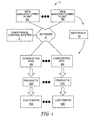
- FIG. 1 is a block diagram illustrating a global network environment 2 in which conversion control system 4 controls conversion of web material. More specifically, web manufacturing plants 6A-6N represent manufacturing sites that produce and ship web material in the form of web rolls 10. Web manufacturing plants 6A-6N may be geographically distributed.
- the manufactured web material may include any sheet-like material having a fixed dimension in one direction and either a predetermined or indeterminate length in the orthogonal direction.
- Examples of web materials include, but are not limited to, metals, paper, wovens, non-wovens, glass, polymeric films, flexible circuits or combinations thereof.
- Metals may include such materials as steel or aluminum.
- Wovens generally include various fabrics.
- Non-wovens include materials, such as paper, filter media, or insulating material.
- Films include, for example, clear and opaque polymeric films including laminates and coated films.
- the web materials of web rolls 10 may have an applied coating, which generally are applied to an exposed surface of the base web material.
- coatings include adhesives, optical density coatings, low adhesion backside coatings, metalized coatings, optically active coatings, electrically conductive or nonconductive coatings, or combinations thereof.
- the coating may be applied to at least a portion of the web material or may fully cover a surface of the base web material. Further, the web materials may be patterned or unpatterned.
- Web rolls 10 are shipped to converting sites 8A-8N, which may be geographically distributed within different countries.
- Converting sites 8A-8N (“converting sites 8") convert each web roll 10 into one or more products.
- each of converting sites 8 includes one or more process lines that physically cut the web for a given web roll 10 into numerous individual sheets, individual parts, or numerous web rolls, referred to as products 12A-12N.
- converting site 8A may convert web rolls 10 of film into individual sheets for end use applications.
- other forms of web materials may be converted into products 12 of different shapes and sizes depending upon the intended application by customers 14A-14N.
- Each of converting sites 8 may be capable of receiving different types of web rolls 10, and each converting site may produce different products 12 depending on the location of the converting site and the particular needs of customers 14.
- each of web manufacturing plants 6 includes one or more inspection systems (not shown in FIG. 1 ) that acquire anomaly information for the produced webs.
- the inspection systems of web manufacturing plants 6 perform preliminary examination of the webs using a first, typically less sophisticated algorithm to identify manufacturing anomalies, accepting the likelihood that although some of the anomalies may prove defective, many could be "false positives," i.e., anomalies that are not defective.
- products 12 have different grade levels, also referred to as quality levels, and have different tolerances for manufacturing anomalies.
- some of the anomaly areas may be ultimately classified as defective if the corresponding web roll 10 is converted to a particular product 12, but not defective if the web roll is converted to a different product.
- Web manufacturing plants 6 communicate image information about the regions of the web containing anomalies to conversion control system 4 via network 9 for subsequent processing.
- Conversion control system 4 applies one or more defect detection algorithms that may be application-specific, i.e., specific to products 12. Based on the analysis, conversion control system 4 determines, in an automated or semi-automated manner, which of products 12 would allow a particular web roll 10 to achieve a maximum yield (i.e., utilization) of the web. Based on the determination, conversion control system 4 generates a conversion plan for each web roll 10, i.e., defined instructions for processing the web roll, and communicates the conversion plan via network 9 to the appropriate converting site 8 for use in converting the web into the selected product.
- Conversion control system 4 may consider other product selection parameters, either in addition to or independent from yield, when generating conversion plans for each of web rolls 10. For example, conversion control system 4 may consider the number of units that would be produced by each of web rolls 10 for the different products 12. Other example product selection parameters that conversion control system 4 may consider when generating a conversion plan include an estimated amount of revenue or profit that would be produced by the web roll for each potential product 12, a process time that would be required to convert the web for each of the different products, a current machine capacity for each process line within converting sites 8, current levels of demand for each of products 12 and other parameters.
- conversion control system 4 may make such determinations for individual converting sites 8: In other words, conversion control system 4 may identify the web rolls destined for each converting site 8, and generate conversion plans based on the products 12 associated with the individual converting sites. For example, conversion control system 4 may identify the web rolls destined for converting site 8A, and generate conversion plans to maximize yield for the web rolls based on the products 12A produced by converting site 8A.
- conversion control system 4 may generate the conversion plans for web rolls 10 prior to their shipment to converting sites 8. Consequently, conversion control system 4 may consider all of the potential available products 12 when generating corresponding conversion plans for web rolls 10. In this manner, conversion control system 4 may consider all of the potentially available products 12 in order to, for example, maximize the yield of each web roll 10. In this configuration, conversion control system 4 generates conversion plans and outputs instructions identifying the specific converting sites 8 to which each of web rolls 10 should be shipped.
- conversion control system 4 considers other parameters when selecting the respective converting sites 8 for web rolls 10. Such parameters include, but are not limited to, current inventory levels of products 12 at each of converting sites 8, recent orders received from customers 14, shipment time and cost associated with each of converting sites 8, methods of available shipment and other parameters.
- conversion control system 4 applies application-specific defect detection algorithms to the anomaly information received from web manufacturing plants 6, and ultimately directs the conversion of web rolls 10 into products 12 based on one or more parameters. As illustrated below, these factors may be user selectable, and may be applied independently or collectively using a weighting function or other technique.
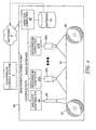
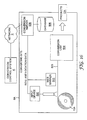
- FIG. 2 is a block diagram illustrating an exemplary embodiment of web manufacturing plant 6A of FIG. 1 .
- a segment of a continuously moving web 20 is positioned between two support rolls 22, 24.
- Image acquisition devices 26A-26N are positioned in close proximity to the continuously moving web 20. Image acquisition devices 26 scan sequential portions of the continuously moving web 20 to obtain image data. Acquisition computers 27 collect image data from image acquisition devices 26, and transmit the image data to analysis computer 28 for preliminary analysis.
- Image acquisition devices 26 may be conventional imaging devices that are capable of reading a sequential portion of the moving web 20 and providing output in the form of a digital data stream. As shown in FIG. 2 , imaging devices 26 may be cameras that directly provide a digital data stream or an analog camera with an additional analog to digital converter. Other sensors, such as, for example, laser scanners may be utilized as the imaging acquisition device. A sequential portion of the web indicates that the data is acquired by a succession of single lines. Single lines comprise an area of the continuously moving web that optically maps to a single row of sensor elements or pixels.
- Examples of devices suitable for acquiring the image include linescan cameras such as Model#LD21 from Perkin Elmer (Sunnyvale, Calif.), Piranha Models from Dalsa (Waterloo, Ontario, Canada), or Model#TH78H15 from Thompson-CSF (Totawa, N.J.). Additional examples include laser scanners from Surface Inspection Systems GmbH (Munich, Germany) in conjunction with an analog to digital converter.
- the image may be optionally acquired through the utilization of optic assemblies that assist in the procurement of the image.
- the assemblies may be either part of a camera, or may be separate from the camera.
- Optic assemblies utilize reflected light, transmitted light, or transflected light during the imaging process. Reflected light, for example, is often suitable for the detection of defects caused by web surface deformations, such as surface scratches.
- Barcode controller 30 controls barcode reader 29 to input roll and position information from web 20. Barcode controller 30 communicates the roll and position information to analysis computer 28.
- Analysis computer 28 processes image streams from acquisition computers 27. Analysis computer 28 processes the digital information with one or more initial algorithms to generate anomaly information that identifies any regions of web 20 containing anomalies that may ultimately qualify as defects. For each identified anomaly, analysis computer 28 extracts from the image data an anomaly image that contains pixel data encompassing the anomaly and possibly a surrounding portion of web 20.
- Database 32 may be implemented in any of a number of different forms including a data storage file or one or more database management systems (DBMS) executing on one or more database servers.
- the database management systems may be, for example, a relational (RDBMS), hierarchical (HDBMS), multidimensional (MDBMS), object oriented (ODBMS or OODBMS) or object relational (ORDBMS) database management system.
- database 32 is implemented as a relational database provided by SQL ServerTM from Microsoft Corporation.
- Analysis computer 28 communicates the roll information as well as anomaly information and respective sub-images to conversion control system 4 for subsequent, offline, detailed analysis.
- the information may be communicated by way of a database synchronization between analysis computer 28 and conversion control system 4.
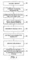
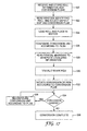
- FIG. 3 is a flowchart illustrating exemplary operation of web manufacturing plant 6A.
- image acquisition devices 26 and acquisition computers 27 acquire image data from moving web 20 (40).
- the image data may be formed digitally, e.g., by way of a digital video camera, or may be converted to digital information (42).
- acquisition computers 27 output streams of digital image information to analysis computer 28 (44).
- Analysis computer 28 applies an initial anomaly detection algorithm to identify regions of the web containing anomalies (46).
- the initial anomaly detection algorithm is very fast so as to be capable of being performed in real time by general purpose computing equipment even if a line speed of moving web 20 is great.
- some of the identified regions containing anomalies may include "false positives.”
- the initial algorithm is preferably designed such that "escapes,” i.e., true defects not detected as anomalies, rarely, if ever occur.
- analysis computer 28 Upon applying the initial anomaly detection algorithm, analysis computer 28 assembles anomaly data about the identified regions and stores the anomaly data within database 32 (48).
- the data typically includes a start position of the anomaly within the web and an encompassing pixel area of each identified region.
- analysis computer 28 extracts a portion of the image data for each identified region containing an anomaly (50).
- the identified regions typically contain information, for example, at least an order of magnitude less than the digital information, as indicated by size in any convenient measure such as file size in bytes. In some applications, the present invention has demonstrated actual data reduction in an order of magnitude of between 3 and 12.
- the extracted anomaly images may be stored in a database 32 or a file server (not shown) (52) and subsequently communicated to conversion control system 4 along with the anomaly and roll information (54). Alternatively, the roll information, anomaly information and anomaly images may be transferred directly for processing by conversion control system 4.
- FIG. 4 is a block diagram illustrating an example embodiment of conversion control system 4 in further detail.
- application server 58 provides an operating environment for software modules 61.
- Software modules include a plurality of defect processing modules 60A-60M, a user interface module 62 and a conversion control engine 64.
- Software modules 61 interact with database 70 to access data 72, which may include anomaly data 72A, roll data 72B, image data 72C, product data 72D, converting site data 72E, defect maps 72F, composite defect maps 72G, conversion control rules 72H, and conversion plans 72I.
- data 72 may include anomaly data 72A, roll data 72B, image data 72C, product data 72D, converting site data 72E, defect maps 72F, composite defect maps 72G, conversion control rules 72H, and conversion plans 72I.
- Database 70 may be implemented in any of a number of different forms including a data storage file or one or more database management systems (DBMS) executing on one or more database servers.
- database 32 is implemented as a relational database provided by SQL ServerTM from Microsoft Corporation.
- Anomaly data 72A, roll data 72B, and image data 72C represent the roll information, anomaly information and respective anomaly images received from web manufacturing plants 6 ( FIG. 1 ).
- Product data 72D represents data associated with products 12 ( FIG. 1 ). More specifically, product data 72D defines each type of product 12 producible by each converting site 8. For each product 12, product data 72D specifies one or more defect processing modules 60 that are required to determine whether a given web roll 10 satisfies the quality requirements for the particular product. In other words, product data 72D specifies one or more defect processing modules 60 that are to be used to analyze anomaly data 72A and image data 72C for each product 12.
- product data 72D stores other information related to products 12 that may be utilized by conversion control system 4 when selecting converting sites 8 and generating conversions plans for web rolls 10.
- product data 72D may further include data specifying an estimated revenue per unit for each of products 12.
- product data 72D may also include data specifying an estimated income per unit for each of products 12, an estimated conversion time to convert a web roll to each product, a current level of industry demand for each of product or other data that may be useful in selecting conversion plans.
- Converting site data 72E represents data associated with converting sites 8.
- converting site data 72E may stores site location, number of process lines and a current available capacity of each process line for each of converting sites 8.
- Converting site data 72E may store other data, including but not limited to, data specifying a current level of inventory for each product 12 at each converting site 8, shipments costs associated with shipping a web roll to each converting site, shipment options available for each converting site, current order information from customers 14 received by each converting site, data specifying new or preferred customers for each converting site, and other data that may be useful in selecting conversion plans.
- defect processing modules 60 output defect maps 72F that specify which anomalies are considered actual defects for the different products 12.
- each defect map 72F corresponds to a particular web roll 10 and a specific product 12.
- Each defect map 72F specifies the particular defect locations of a particular web roll 10 based on the product-specific requirements of the corresponding product 12.
- Conversion control engine 64 analyzes defect maps 72F in accordance with conversion control rules 72H to select the ultimate conversion used for each of the web rolls 10. For example, conversion control engine 64 may analyze defect maps 72F to determine which of products 12 would allow a particular web roll 10 to achieve a maximum yield (i.e., utilization) of the web.
- Conversion control rules 72H specify one or more parameters for consideration by conversion control engine 64 when processing defect maps 72F, such as usage of web material, the number of units that would be produced by each of web rolls 10 for the different products 12, an estimated amount of revenue or profit that would be produced by the web roll for each potential product 12, a process time that would be required to convert the web for each of the different products, a current machine capacity for each process line within converting sites 10, current levels of demand for each of products 12 and other parameters.
- conversion control engine 64 may determine that a particular web roll 10 may be best utilized (e.g., may achieve maximum yield) if converted into multiple products 12. In other words, conversion control engine 64 may determine that a first portion of the web may be best utilized when converted to a first product, and a second portion for a different product. In this case, conversion control engine 64 generates a "composite" defect map 72G that specifies the defect locations within each portion of the web based on the corresponding product to which the portion is to be converted. Conversion control engine 64 may create the composite defect maps by splicing portions of two or more defect maps 72F to form a complete, composite defect map for the entire web.
- conversion control engine 64 Upon selecting a particular product or set of products for a given web roll 10, conversion control engine 64 generates a respective conversion plan 72I.
- Each conversion plan 72I provides precise instructions for processing the respective web roll. More specifically, each conversion plan 72I defines configurations for processing lanes to physically slice the web into individual product sheets.
- Conversion control system 4 outputs shipment instructions directing the shipment of each web roll 10 to a respective destination converting site 8. Further, conversion control system 4 communicates conversion plans via network 9 to the appropriate converting sites 8 for use in converting the web rolls into the selected products.
- User interface module 62 provides an interface by which a user can configure the parameters used by conversion control engine 64. For example, as illustrated below, user interface module 62 allows the user to direct conversion control engine 64 to consider one or more of a maximum web utilization, number of units produced, estimated revenue, estimated profit, machine capacity, current levels of demand and/or other parameters.
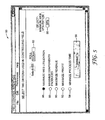
- FIG. 5 is an example user interface 80 presented by user interface module 62 with which a user interacts to configure conversion control engine 64.
- Exemplary interface 80 includes input mechanism 82 by which the user enters a unique identifier for a web roll.
- Other mechanisms for selecting a roll may be used, such as a drop-down menu, search function, selectable list of recently manufactured rolls or the like.
- user interface 80 provides a plurality of input mechanisms 86-94 by which the user can select one or more product selection parameters for consideration by conversion control engine 64 when generating a recommended conversion plan.
- user interface 80 includes a first input selection mechanism 86 to direct conversion control engine 64 to select a conversion plan that seeks to optimize the web utilization for the selected web roll.
- Input mechanism 88 directs conversion control engine 64 to maximize the number of components produced from selected web roll.
- input mechanisms 90, 92 direct conversion control engine 64 to maximize the revenue and profit generated from selected web roll, respectfully.
- Input mechanism 94 directs conversion control engine 64 to select a conversion plan that minimizes the process time for selected web roll.
- SUBMIT button 98 which directs conversion control system 4 to process the selected web roll with defect processing modules 60, followed by analysis and conversion plan selection by conversion control engine 64.
- user interface 80 provides a simplistic illustration of how a user may configure conversion control engine 64 based on one or more parameters.
- User interface 80 may require the user to select one and only one of the input mechanisms 86-94.
- user interface 80 includes an input mechanism 96 that allows the user to define a minimum web utilization. This may be advantageous in situations where the user selects a primary parameter, such as profit, to be maximized, but desires a baseline utilization to be met.
- FIG. 6 provides another exemplary user interface 100 presented by user interface module 62.
- exemplary interface 100 includes input mechanisms 102-110 by which the user enters respective weighting functions for each parameter.
- input mechanism 102 allows the user to enter a weighting function ranging from 0 to 100 for each parameter, where 0 directs conversion control engine 64 to exclude the parameter and 100 represents the highest possible weighting.
- Defect processing modules 60 analyze the anomaly data for the selected web roll when the user selects SUBMIT button 112, followed by analysis and conversion plan selection by conversion control engine 64.
- conversion control engine 64 may analyze defect maps 72F for each potential product 12 for each of the parameters having non-zero weightings. In the example of FIG. 6 , conversion control engine 64 analyzes the defect maps 72F and product data 72D to compute web utilization, number of components produced, profit generated and process time for each potential product. As described in further detail below, conversion control engine 64 may then normalize the computed results of each parameter for each product, and then compute weighted values from the normalized results. Finally, conversion control engine 64 selects a conversion plan as a function of (e.g., a sum) of the weighted values. Other technique may be utilized in which conversion control system 4 utilizes multiple parameters when selecting a conversion plan for a web roll 10.
- FIG. 7 is a flow diagram that illustrates the processing of anomaly information by conversion control system 4 in further detail.
- FIG. 7 illustrates the processing of anomaly data 72A and image data 72C by defect processing modules 60.
- Conversion control system 4 receives the image and anomaly data, such as images 144, 146, that were extracted initially from a web 20 by an analysis computer 28 located at a web manufacturing plant 6 using a simple first detection algorithm.
- defect processing modules 60 apply "M" different algorithms (designated A 1 -A m 158 in FIG. 7 ) as needed for up to N different requirements 150 for products 12.
- Cross-reference table 152 of FIG. 7 is used to illustrate the mapping between requirements 150 and defect processing modules 60. Specifically, cross-reference table 152 shows which defect processing modules 60 are utilized in determining whether each anomaly is a defect or a false positive for a given requirement 150.
- a larger number of rather simpler algorithms are conveniently used in parallel.
- at least one of the subsequent defect processing modules 60 apply an algorithm that includes comparing each anomaly against a combination threshold-pixel size criterion.
- a combination threshold-pixel size criterion In actual practice with, for example, optical films, an anomaly having only a subtle difference in brightness value from a target is unacceptable if the area is large, and an anomaly having a great difference in brightness from a target value is unacceptable even if the area is very small.
- the algorithms applied by defect processing modules 60 can incorporate very complex image processing and defect extraction including, but not limited to, neighborhood averaging, neighborhood ranking, contrast expansion, various monadic and dyadic image manipulations, digital filtering such as Laplacian filters, Sobel operators, high-pass filtering and low-pass filtering, texture analysis, fractal analysis, frequency processing such as Fourier transforms and wavelet transforms, convolutions, morphological processing, thresholding, connected component analyses, blob processing, blob classifications, or combinations thereof.
- Other algorithms may be applied based on the specific web and defect types to achieve a desired accuracy level of defect detection.
- Each of the N product requirements 150 can be accomplished using selected combinations of individual defect processing algorithms 158.
- the algorithms may use very simple threshold and minimum blob processing or more complex algorithms such as spatial filters, morphological operations, frequency filters, wavelet processing, or any other known image processing algorithms.
- product requirement R 1 uses a combination of algorithms A 2 , A 4 , and A M , each applied to every anomaly image to determine which anomalies are actual defects for R 1 .
- a simple OR logic is employed, i.e. if any of A 2 , A 4 , and A M report the anomaly as an actual defect, that portion of web 20 does not satisfy product requirement R 1 .
- the logic through which the reports of the subsequent algorithms 158 are combined into a determination of whether a product requirement 150 is satisfied may be more complex than a simple OR logic.
- product requirement R 2 uses A 2 , A 3 , and A 4 , etc.
- the anomalies that are identified as defects for R 2 may be similar to or significantly different than defects for R 1 .
- conversion control engine 64 formulates defect maps 72F of actual defect locations corresponding to the various product requirements for the roll.
- conversion control engine 64 may generate one or more composite defect maps 72G by splicing one or more portions of defect maps 72F.
- conversion control engine 64 generates a composite map 72G having a first portion 160 spliced from a defect map for a first product requirement (MAP-R1) and a second portion 162 from a defect map for a second product requirement (MAP-R2).
- MAP-R1 first product requirement
- MAP-R2 second product requirement
- conversion control engine 64 may determine that a web may be best utilized if certain portions of the web are converted into different products. Once this has been done, it is often possible to discard the subimage information to minimize the needed storage media.
- FIGS. 8-15 are flowcharts illustrating various exemplary embodiments in which conversion control engine 64 applies conversion rules 72H to generate conversion plans 72I based on one or more user-configurable parameters, such as usage of web material, number of units produced, revenue, profit, process time, machine capacity, product demand and other parameters.
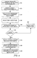
- FIG. 8 is a flowchart illustrating one exemplary method in which conversion control engine 64 selects a conversion plan 72I for a given web roll 10 to maximize web utilization.
- conversion control engine 64 identifies a set of potential products 12 into which the web roll 10 may be converted (200). As described above, if the web roll has been or is currently being shipped to a particular converting site 8, conversion control engine 64 selects one or more of the products associated with the specific converting site for which the web roll is suitable. Alternatively, if the web roll being considered has not been shipped, conversion control system 4 may select all of products 12 for which the web roll is suitable.
- Conversion control engine 64 accesses product data 72D of database 70 to identify the product requirements for the identified set of suitable products, and selects one or more of the defect processing modules 60 based on the identified requirements (202).
- conversion control engine 64 invokes the selected defect processing modules 60, which apply respective defect detection algorithms to anomaly data 72A and image data 72C received from a web manufacturing plant 6 to formulate defect information for each of the product requirements. Conversion control engine 64 generates defect maps 72F based on the defects identified by defect processing modules 60 (204).
- conversion control engine 64 selects a first one of the defect maps (206), and analyzes the map to calculate a yield for the web, either in percentage of material utilized, actual area utilized or some other convenient metric (208). Conversion control engine 64 repeats this process for each defect map (210, 212).
- Conversion control engine 64 selects the product that would result in the maximum yield for the web roll (214). Conversion control engine 64 identifies the defect map associated with the selected product, and generates a conversion plan 72I in accordance with the selected defect map (216).
- Conversion control engine 64 may further communicate the conversion plan to the appropriate converting site 8, and output (e.g., display or print) shipment instructions for shipping the particular web roll 10 to the converting site (218).
- FIG. 9 is a flowchart illustrating an exemplary method in which conversion control engine 64 generates a conversion plan 72I for a given web roll 10 to maximize the number of components produced from the web roll.
- conversion control engine 64 identifies a set of potential products 12 into which the web roll 10 may be converted, and selectively invokes one or more of the defect processing modules 60 to apply defect detection algorithms and generates defect maps 72F for the web roll (220-224).
- conversion control engine 64 selects a first one of the defect maps (226), and analyzes the map to calculate a total number of components that could be produced for the respective product (228). Conversion control engine 64 repeats this process for each defect map (230, 232).
- Conversion control engine 64 selects the product that would result in the maximum number of components produced by the web roll (234). For example, based on the specific locations of the defects, few components may be realizable for a larger sized product (e.g., a film for a computer screen) versus a smaller sized product (e.g., a film for a mobile phone display).
- a larger sized product e.g., a film for a computer screen
- a smaller sized product e.g., a film for a mobile phone display
- Conversion control engine 64 generates a conversion plan 72I based on the selected product, communicates the conversion plan to the appropriate converting site 8, and outputs (e.g., display or print) shipment instructions for shipping the particular web roll 10 to the converting site (236-238).
- FIG. 10 is a flowchart illustrating an exemplary method in which conversion control engine 64 generates a conversion plan 72I for a given web roll 10 to maximize a total unit sales volume realized from the web roll.
- conversion control engine 64 identifies a set of potential products 12 into which the web roll 10 may be converted, and selectively invokes one or more of the defect processing modules 60 to apply defect detection algorithms and generates defect maps 72F for the web roll (250-254).
- conversion control engine 64 selects a first one of the defect maps (256), and analyzes the map to calculate a total number of components that could be produced for the respective product (257).
- conversion control engine 64 accesses product data 72D to retrieve an estimated sale price per unit for the particular product. Based on the estimated sale price, conversion control engine 64 calculates a total estimated sales (e.g., in dollars) that would be generated from the web roll if the web roll were converted into the product (258). Conversion control engine 64 repeats this process for each defect map (260, 262).
- Conversion control engine 64 selects the product that would result in the maximum amount of realized sales, i.e., revenue, for the web roll (264). For example, certain components may better capture a premium price than other components due to market factors. In this exemplary embodiment, conversion control engine 64 may select a product that does not achieve a maximum utilization of the web roll, but nevertheless is expected to generate higher sales relative to the other suitable products.
- Conversion control engine 64 generates a conversion plan 72I based on the selected product, communicates the conversion plan to the appropriate converting site 8, and outputs (e.g., display or print) shipment instructions for shipping the particular web roll 10 to the converting site (266-268).
- FIG. 11 is a flowchart illustrating an exemplary method in which conversion control engine 64 generates a conversion plan 72I for a given web roll 10 to maximize a total profit realized from the web roll.
- conversion control engine 64 identifies a set of potential products 12 into which the web roll 10 may be converted, and selectively invokes one or more of the defect processing modules 60 to apply defect detection algorithms and generates defect maps 72F for the web roll (270-274).
- Conversion control engine 64 selects a first one of the defect maps (276), and analyzes the map to calculate a total number of components that could be produced for the respective product (277). Next, conversion control engine 64 accesses product data 72D to retrieve an estimated sales price and estimated cost per unit for the particular product. Based on the estimated sales price and cost, conversion control engine 64 calculates a total estimated profit realized from the web roll if the web roll were converted into the product (278). Conversion control engine 64 repeats this process for each defect map (280, 282).
- Conversion control engine 64 selects the product that would result in the maximum amount of profit realized for the web roll (284). Conversion control engine 64 generates a conversion plan 72I based on the selected product, communicates the conversion plan to the appropriate converting site 8, and outputs (e.g., display or print) shipment instructions for shipping the particular web roll 10 to the converting site (286-288).
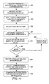
- FIG. 12 is a flowchart illustrating an exemplary method in which conversion control engine 64 generates a conversion plan 72I for a given web roll 10 to minimize process time yet achieve a required minimum yield.
- conversion control engine 64 identifies a set of potential products 12 into which the web roll 10 may be converted, and selectively invokes one or more of the defect processing modules 60 to apply defect detection algorithms and generates defect maps 72F for the web roll (300-304).
- conversion control engine 64 selects a first one of the defect maps (306), and analyzes the map to calculate a yield that would be produced for the respective product, either as a percentage of material utilized, actual area utilized or some other convenient metric (308). Conversion control engine 64 repeats this process for each defect map (310, 312).
- Conversion control engine 64 then ranks the products according to the estimated yield (314), and selects a subset of the products including only those products that would achieve a defined minimum yield (316). Next, conversion control engine 64 ranks the subset of products according to a process time, as specified in product data 72D (318). Conversion control engine 64 then selects the product from the subset of products that has the lowest estimated process time (320). Conversion control engine 64 generates a conversion plan 72I based on the selected product, communicates the conversion plan to the appropriate converting site 8, and outputs (e.g., display or print) shipment instructions for shipping the particular web roll 10 to the converting site (322-324). In this manner, conversion control engine 64 defines a conversion plan 72I for web roll 10 to achieve an acceptable yield level while minimizing conversion time (i.e., maximizing throughput) of the web at converting sites 8.
- FIG. 13 is a flowchart illustrating an exemplary method in which conversion control engine 64 generates a conversion plan 72I for a given web roll 10 to maximize utilization of process lines at converting sites 8, yet achieve a required minimum yield for the web roll.
- conversion control engine 64 identifies a set of potential products 12 into which the web roll 10 may be converted, and selectively invokes one or more of the defect processing modules 60 to apply defect detection algorithms and generates defect maps 72F for the web roll (340-344).
- conversion control engine 64 selects a first one of the defect maps (346), and analyzes the map to calculate a yield that would be produced for the respective product, either as a percentage of material utilized, actual area utilized or some other convenient metric (348). Conversion control engine 64 repeats this process for each defect map (350, 352).
- Conversion control engine 64 then ranks the products according to the estimated yield (354), and selects a subset of the products including only those products that would achieve a defined minimum yield (356). Next, conversion control engine 64 accesses converting site data 72E to determine a set of process lines of converting sites 8 suitable for converting the subset of products. Conversion control engine 64 ranks the identified process lines according to current unutilized capacity (358). Conversion control engine 64 then selects the product from the subset of products that corresponds to the process line having the highest unutilized capacity (360).
- Conversion control engine 64 generates a conversion plan 72I based on the selected product, communicates the conversion plan to the appropriate converting site 8, and outputs (e.g., display or print) shipment instructions for shipping the particular web roll 10 to the converting site (362-364). In this manner, conversion control engine 64 defines a conversion plan 72I for web roll 10 to achieve an acceptable yield level while maximizing the utilization of the process lines of converting sites 8.
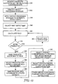
- FIG. 14 is a flowchart illustrating an exemplary method in which conversion control engine 64 generates a conversion plan 72I for a given web roll 10 based on a composite defect map to convert the web roll into two or more products to maximize utilization of the web roll.
- conversion control engine 64 identifies a set of potential products 12 into which the web roll 10 may be converted, and selectively invokes one or more of the defect processing modules 60 to apply defect detection algorithms and generates defect maps 72F for the web roll (380-384).
- conversion control engine 64 analyzes the defect maps to define regions of the maps based on yield (386). For example, as illustrated in FIG. 7 , based on the analysis, conversion control engine 64 may define a first region of one of the defect maps that would result in a relatively high yield for a first product, and a second non-overlapping region of a different product map that would result in a high yield for a second product.
- Conversion control engine 64 ranks and selects the non-overlapping regions based on estimated yield (390), and generates a composite defect map 72G by splicing the non-overlapping regions to form the composite defect map (392). In this manner, conversion control engine 64 may determine that a web may be best utilized if certain portions of the web are converted into different products.
- Conversion control engine 64 generates a conversion plan 72I based on the composite defect map, communicates the conversion plan to the appropriate converting site 8, and outputs (e.g., display or print) shipment instructions for shipping the particular web roll 10 to the converting site (362-364). In this manner, conversion control engine 64 defines a conversion plan 72I for web roll 10 to convert the web roll into two or more products to maximize utilization of the web roll.
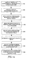
- FIG. 15 is a flowchart illustrating an exemplary method in which conversion control engine 64 generates a conversion plan 72I for a given web roll 10 based on a weighted average of a plurality of configurable parameters.
- Conversion control engine 64 identifies a set of potential products 12 into which the web roll 10 may be converted, and selectively invokes one or more of the defect processing modules 60 to apply defect detection algorithms and generates defect maps 72F for the web roll (400-404).
- conversion control engine 64 employs any of the described techniques to calculate the specified parameters, e.g., web utilization, component yield, profit, sales, process capacity, process time or other parameters for each of the products (406). Conversion control engine 64 then normalizes each of the parameters to a common range, such as 0 to 100 (408).
- Conversion control engine 64 then adjusts each of the parameters in accordance with a user-configurable weighting, as shown in FIG. 6 (410), and computes a total weighted average for each product (412). Conversion control engine 64 selects the product corresponding to the maximum weighted average of the parameters (414), generates a conversion plan 72I for the selected product.based on the respective defect map (416).
- Conversion control engine 64 communicates the conversion plan to the appropriate converting site 8, and outputs (e.g., display or print) shipment instructions for shipping the particular web roll 10 to the converting site (418). In this manner, conversion control engine 64 may consider multiple parameters when defining a conversion plan 72I for converting the web roll into products based on stored image anomaly information.
- FIG. 16 is a block diagram illustrating one embodiment of a converting site 8A.
- converting site 8A includes a web roll 10A that has been loaded and readied for conversion.
- Conversion server 508 receives conversion maps from conversion control system 4, and stores the conversion maps in database 506.
- a barcode is read from roll 10A, which informs conversion server 508 of the particular web 503, allowing the conversion server to access database 506 and retrieve the corresponding conversion map.
- the barcode may be read by input device 500 when web 503 is placed in motion or via a hand-held barcode device prior to loading.
- Conversion server 508 displays a conversion plan, thereby allowing workers to configure conversion unit 504.
- conversion unit 504 is configured to physically cut web 503 into numerous individual sheets (i.e., products 12A) in accordance with the conversion plan.
- input device 500 reads barcodes and associated fiducial marks are regularly sensed.
- the combination of barcode and fiducial mark enables one to precisely register the physical position of web 503 to the defects identified in the conversion plan. Regular re-registration ensures ongoing registration accuracy.
- One skilled in the art is capable of establishing the re-registration through conventional physical coordinate transformation techniques.
- web marker 502 When defects pass under web marker 502, marks are applied to web 503 to visually identify the defects. Specifically, conversion server 508 outputs a series of commands to a web marker 502, which then applies locating marks to the web 503. In many applications of the present invention, web marker 502 places the locating marks on or adjacent to the defects within web 503 in accordance with the respective conversion plan. However, in some specialized applications the locating marks are spaced in a predetermined way from the anomalies whose position they identify. Web marker 502 may include, for example, a series of ink-jet modules, each having a series of jet nozzles.
- the type of mark and the exact position of the mark on or near the defect may be selected based upon the web material, defect classification, web processing required to address the defect, and the intended end use application of the web.
- markers are fired preferentially depending on their cross-web position as defects pass the unit in the down-web direction.
- Conversion server 508 may pause the conversion of web 503 at any point in accordance with the conversion plan to allow reconfiguration of conversion unit 504. For example, in the even web 503 is to be converted to different products, conversion server 508 halts the conversion process after the first product is produced to allow conversion unit 504 to be reconfigured for the subsequent product. Positioning of cutting devices and other mechanisms, for example, may be reconfigured as needed to produce the second product.
- FIG. 17 is a flowchart illustrating exemplary operation of a converting site, such as converting site 8A of FIG. 16 , in processing a web in accordance with conversion plans to achieve, for example, a maximum yield or other configurable parameter.
- conversion server 508 receives and stores roll information and conversion plans from conversion control system 4 (520). This may happen prior to or after receiving web rolls. For example, conversion server 508 may receive roll information and a conversion plan for a particular web roll weeks before the physical web roll arrives at the converting sites. Alternatively, conversion server 508 may receive roll information and a conversion plan for a web roll already stored within inventory at the converting site.
- conversion server 508 receives barcode information, for a particular web roll to be converted, causing conversion server 508 to access database 506 and retrieve the corresponding conversion map (522).
- the barcode may be read prior to loading (e.g., by a hand-held barcode device), as illustrated in FIG. 17 , or via input device 500 after web 503 is loaded and readied for conversion.
- Conversion server 508 displays a conversion plan, thereby allowing workers to configure conversion unit 504 to physically cut web 503 into numerous individual sheets (i.e., products 12A) in accordance with the conversion plan (526).
- conversion unit 504 may be configured in an automated or semi-automated manner in accordance with the conversion plan.
- conversion unit 504 converts the received web 503 to form products 12A (532).
- conversion server 508 may determine that a reconfiguration is required by the plan (534). If so, conversion server 508 directs the reconfiguration of conversion unit 504 (536). This process continues until all of web 503 is converted to one or more products 12A in accordance with the conversion plan (538).
Applications Claiming Priority (2)
| Application Number | Priority Date | Filing Date | Title |
|---|---|---|---|
| US53359503P | 2003-12-31 | 2003-12-31 | |
| EP04815898A EP1704589A4 (de) | 2003-12-31 | 2004-12-29 | Maximierung der ausbeute für web-gestützte artikel |
Related Parent Applications (1)
| Application Number | Title | Priority Date | Filing Date |
|---|---|---|---|
| EP04815898.4 Division | 2004-12-29 |
Publications (1)
| Publication Number | Publication Date |
|---|---|
| EP2339419A1 true EP2339419A1 (de) | 2011-06-29 |
Family
ID=34748923
Family Applications (2)
| Application Number | Title | Priority Date | Filing Date |
|---|---|---|---|
| EP04815898A Withdrawn EP1704589A4 (de) | 2003-12-31 | 2004-12-29 | Maximierung der ausbeute für web-gestützte artikel |
| EP11157019A Withdrawn EP2339419A1 (de) | 2003-12-31 | 2004-12-29 | Maximierung des Ausbeute von Artikeln aus Bahnen-Materialien |
Family Applications Before (1)
| Application Number | Title | Priority Date | Filing Date |
|---|---|---|---|
| EP04815898A Withdrawn EP1704589A4 (de) | 2003-12-31 | 2004-12-29 | Maximierung der ausbeute für web-gestützte artikel |
Country Status (6)
| Country | Link |
|---|---|
| US (1) | US7187995B2 (de) |
| EP (2) | EP1704589A4 (de) |
| JP (1) | JP2007517232A (de) |
| KR (1) | KR20060128979A (de) |
| BR (1) | BRPI0418268A (de) |
| WO (1) | WO2005065367A2 (de) |
Families Citing this family (34)
| Publication number | Priority date | Publication date | Assignee | Title |
|---|---|---|---|---|
| AU2002328521A1 (en) * | 2002-08-29 | 2004-03-29 | Fujitsu Frontech Limited | Bar code reader, bar code reading method, bar code reading program, and module point extracting device |
| US7623699B2 (en) * | 2004-04-19 | 2009-11-24 | 3M Innovative Properties Company | Apparatus and method for the automated marking of defects on webs of material |
| US20060090319A1 (en) * | 2004-11-01 | 2006-05-04 | Howe Major K | Defect locating system for moving web |
| JP5248052B2 (ja) * | 2006-10-11 | 2013-07-31 | 日東電工株式会社 | 光学フィルムを有するシート状製品の欠点検査装置、その検査データ処理装置、その切断装置及びその製造システム |
| JP5529094B2 (ja) * | 2006-10-11 | 2014-06-25 | 日東電工株式会社 | 光学フィルムを有するシート状製品の検査データ処理装置および切断装置 |
| US8032246B2 (en) * | 2007-02-02 | 2011-10-04 | Kimberly-Clark Worldwide, Inc. | Winding method for uniform properties |
| KR101442871B1 (ko) * | 2007-02-16 | 2014-09-19 | 쓰리엠 이노베이티브 프로퍼티즈 컴파니 | 시트 재료 조명 시스템 및 방법 |
| US20080233404A1 (en) * | 2007-03-22 | 2008-09-25 | 3M Innovative Properties Company | Microreplication tools and patterns using laser induced thermal embossing |
| WO2008148095A1 (en) * | 2007-05-25 | 2008-12-04 | Astralux, Inc. | Hybrid silicon/non-silicon electronic device with heat spreader |
| US8175739B2 (en) * | 2007-07-26 | 2012-05-08 | 3M Innovative Properties Company | Multi-unit process spatial synchronization |
| US20090028417A1 (en) * | 2007-07-26 | 2009-01-29 | 3M Innovative Properties Company | Fiducial marking for multi-unit process spatial synchronization |
| US7542821B2 (en) | 2007-07-26 | 2009-06-02 | 3M Innovative Properties Company | Multi-unit process spatial synchronization of image inspection systems |
| WO2009042638A2 (en) * | 2007-09-27 | 2009-04-02 | Abb Ltd. | Accurate tracking of web features through converting processes |
| US7937233B2 (en) * | 2008-04-17 | 2011-05-03 | 3M Innovative Properties Company | Preferential defect marking on a web |
| US7797133B2 (en) * | 2008-09-10 | 2010-09-14 | 3M Innovative Properties Company | Multi-roller registered repeat defect detection of a web process line |
| US8145344B2 (en) * | 2009-06-02 | 2012-03-27 | The Procter & Gamble Company | Systems and methods for controlling phasing of advancing substrates in absorbent article converting lines |
| US8145338B2 (en) * | 2009-06-02 | 2012-03-27 | The Procter & Gamble Company | Systems and methods for detecting and rejecting defective absorbent articles from a converting line |
| US8145343B2 (en) * | 2009-06-02 | 2012-03-27 | The Procter & Gamble Company | Systems and methods for controlling registration of advancing substrates in absorbent article converting lines |
| US8270701B2 (en) * | 2010-01-08 | 2012-09-18 | 3M Innovative Properties Company | Optical web-based defect detection using intrasensor uniformity correction |
| US8935104B2 (en) * | 2010-03-10 | 2015-01-13 | 3M Innovative Properties Company | Application-specific repeat defect detection in web manufacturing processes |
| KR101315102B1 (ko) * | 2011-07-25 | 2013-10-07 | 동우 화인켐 주식회사 | 필름의 수율 예측 시스템 및 방법 |
| US10119225B2 (en) | 2014-04-15 | 2018-11-06 | Gpcp Ip Holdings Llc | Systems for controlling a manufacturing line used to convert a paper web into paper products by reading marks on the paper web |
| KR101717846B1 (ko) * | 2014-07-22 | 2017-03-17 | 주식회사 엘지화학 | 재단 제품의 생산방법 및 재단 시스템 |
| WO2017034892A1 (en) | 2015-08-21 | 2017-03-02 | 3M Innovative Properties Company | Optical films having an optical axis and systems and methods for processing same |
| CN108475294B (zh) | 2016-01-15 | 2023-04-04 | 康宁股份有限公司 | 表征多孔陶瓷制品的等静压强度的非接触式方法 |
| CA2976640C (en) * | 2016-08-17 | 2022-09-06 | Les Emballages Trium Inc. | Process for manufacturing bags for packaging items, and bag produced therefrom |
| DE102017108496B4 (de) * | 2017-04-21 | 2023-06-29 | Windmöller & Hölscher Kg | Verfahren und Vorrichtungen sowie System zum Auf- und Abwickeln eines Wickels |
| US11520544B2 (en) | 2017-07-14 | 2022-12-06 | Georgia-Pacific Corrugated Llc | Waste determination for generating control plans for digital pre-print paper, sheet, and box manufacturing systems |
| US20190016551A1 (en) * | 2017-07-14 | 2019-01-17 | Georgia-Pacific Corrugated, LLC | Reel editor for pre-print paper, sheet, and box manufacturing systems |
| US11485101B2 (en) * | 2017-07-14 | 2022-11-01 | Georgia-Pacific Corrugated Llc | Controls for paper, sheet, and box manufacturing systems |
| US10642551B2 (en) * | 2017-07-14 | 2020-05-05 | Georgia-Pacific Corrugated Llc | Engine for generating control plans for digital pre-print paper, sheet, and box manufacturing systems |
| US11449290B2 (en) | 2017-07-14 | 2022-09-20 | Georgia-Pacific Corrugated Llc | Control plan for paper, sheet, and box manufacturing systems |
| TW201926024A (zh) * | 2017-11-22 | 2019-07-01 | 財團法人資訊工業策進會 | 紡織機台的調整方法及其系統 |
| CN115808382B (zh) * | 2023-02-02 | 2023-04-21 | 深圳裕典通微电子科技有限公司 | 一种应用于压力传感器的压电薄膜在线检测方法及系统 |
Citations (3)
| Publication number | Priority date | Publication date | Assignee | Title |
|---|---|---|---|---|
| US20020030704A1 (en) * | 2000-08-07 | 2002-03-14 | Korngold Bruno Alexander | Position indication on photographic base |
| US20020082739A1 (en) * | 2000-12-22 | 2002-06-27 | Fuji Photo Film Co., Ltd. | Method of and apparatus for manufacturing products |
| US20030025027A1 (en) * | 2001-08-02 | 2003-02-06 | Fuji Photo Film Co., Ltd. | Production managing method for photo film production |
Family Cites Families (72)
| Publication number | Priority date | Publication date | Assignee | Title |
|---|---|---|---|---|
| US3759620A (en) * | 1972-05-30 | 1973-09-18 | Philco Ford Corp | Flaw detection and marking apparatus |
| US4173441A (en) * | 1977-03-28 | 1979-11-06 | E. I. Du Pont De Nemours And Company | Web inspection system and method therefor |
| US4211132A (en) * | 1977-11-21 | 1980-07-08 | E. I. Du Pont De Nemours And Company | Apparatus for on-line defect zoning |
| US4330356A (en) * | 1980-06-18 | 1982-05-18 | Philip Morris, Incorporated | Web marking apparatus and method |
| DE3305907A1 (de) * | 1983-02-21 | 1984-08-30 | Anton Cramer GmbH & Co KG, 4402 Greven | Verfahren und vorrichtung zum anzeichnen von gasdurchlaessigen stoff- und anderen warenbahnen, insbesondere zum automatischen anzeichnen in einer anzeichnungsstation |
| DE3325125C1 (de) * | 1983-07-12 | 1985-02-14 | Erwin Sick Gmbh Optik-Elektronik, 7808 Waldkirch | Anordnung zur Markierung von Fehlstellen an schnell laufenden Materialbahnen |
| US4877323A (en) * | 1984-11-23 | 1989-10-31 | Stillwagon W C | Method and apparatus for inspecting a high speed web |
| JP2602201B2 (ja) * | 1985-04-12 | 1997-04-23 | 株式会社日立製作所 | 被検査パターンの欠陥検査方法 |
| US4629312A (en) * | 1985-10-02 | 1986-12-16 | Lucht Engineering, Inc. | Thermal marking system for photographic media |
| JPS6293637A (ja) | 1985-10-21 | 1987-04-30 | Hitachi Ltd | 自動検反システム |
| US4700627A (en) * | 1986-01-28 | 1987-10-20 | Case-Hoyt | Method and apparatus for marking defective portions of a printed web |
| GB8620430D0 (en) * | 1986-08-22 | 1986-10-01 | Plessey Co Plc | Marking of articles |
| DE3629004A1 (de) * | 1986-08-27 | 1988-03-10 | Agie Ag Ind Elektronik | Stromzufuehrung fuer eine drahtelektrode einer elektroerosionsmaschine |
| FR2608960B1 (fr) * | 1986-12-31 | 1989-11-24 | Loriot Jean Marc | Procede et dispositif de decoupage d'un tissu a motif repetitif |
| US4752897A (en) * | 1987-05-01 | 1988-06-21 | Eastman Kodak Co. | System for monitoring and analysis of a continuous process |
| US4828156A (en) * | 1987-10-08 | 1989-05-09 | Ncr Corporation | Web monitoring system |
| US4951223A (en) * | 1989-03-28 | 1990-08-21 | Langdon Wales R | Web material inspection system |
| US5062331A (en) * | 1989-08-07 | 1991-11-05 | Eastman Kodak Company | Apparatus and method for edge notching a continuously moving web |
| IL99823A0 (en) | 1990-11-16 | 1992-08-18 | Orbot Instr Ltd | Optical inspection method and apparatus |
| US5440648A (en) * | 1991-11-19 | 1995-08-08 | Dalsa, Inc. | High speed defect detection apparatus having defect detection circuits mounted in the camera housing |
| JP2827651B2 (ja) * | 1992-01-20 | 1998-11-25 | 日本鋼管株式会社 | 鋼板の欠陥有害度測定装置 |
| JPH07509084A (ja) * | 1992-07-13 | 1995-10-05 | ミネソタ マイニング アンド マニュファクチャリング カンパニー | 走査される画像に於ける対象物をカウントする方法及びその装置 |
| US5365596A (en) * | 1992-12-17 | 1994-11-15 | Philip Morris Incorporated | Methods and apparatus for automatic image inspection of continuously moving objects |
| US5305392A (en) * | 1993-01-11 | 1994-04-19 | Philip Morris Incorporated | High speed, high resolution web inspection system |
| US5305707A (en) * | 1993-03-26 | 1994-04-26 | Robert Ryder | Web marking device |
| US5544256A (en) * | 1993-10-22 | 1996-08-06 | International Business Machines Corporation | Automated defect classification system |
| ATE171738T1 (de) * | 1993-11-24 | 1998-10-15 | Retech Ag | Verfahren zur verfolgung von fehlern in textilen warenbahnen |
| US5434629A (en) * | 1993-12-20 | 1995-07-18 | Focus Automation Systems Inc. | Real-time line scan processor |
| US5563809A (en) | 1994-04-06 | 1996-10-08 | Abb Industrial Systems, Inc. | Measurement/control of sheet material using at least one sensor array |
| JPH08145911A (ja) * | 1994-11-15 | 1996-06-07 | Furukawa Electric Co Ltd:The | Al板の表面欠陥自動検査法 |
| US5710420A (en) * | 1995-12-05 | 1998-01-20 | Xerox Corporation | Method for embedding and recovering machine-readable information |
| US5760414A (en) * | 1995-12-19 | 1998-06-02 | Monarch Marking Systems, Inc. | Web of record members and method of and apparatus for making same and system for detecting indicia |
| US6031931A (en) * | 1996-03-15 | 2000-02-29 | Sony Corporation | Automated visual inspection apparatus |
| JP3975408B2 (ja) * | 1996-08-20 | 2007-09-12 | ウステル・テヒノロジーズ・アクチエンゲゼルシヤフト | 繊維面組織における欠陥を認識する方法及び装置 |
| US5774177A (en) * | 1996-09-11 | 1998-06-30 | Milliken Research Corporation | Textile fabric inspection system |
| SE511822C2 (sv) * | 1996-11-13 | 1999-11-29 | Svante Bjoerk Ab | Anordning och metod för att markera defekter på en transparent remsa |
| US6092059A (en) * | 1996-12-27 | 2000-07-18 | Cognex Corporation | Automatic classifier for real time inspection and classification |
| FR2761475B1 (fr) * | 1997-03-28 | 1999-06-11 | Lorraine Laminage | Procede d'inspection de surface d'une bande en defilement par segmentation d'image en zones suspectes |
| KR100303608B1 (ko) * | 1997-05-22 | 2001-11-22 | 박호군 | 혈구세포자동인식방법및장치 |
| TW331650B (en) * | 1997-05-26 | 1998-05-11 | Taiwan Semiconductor Mfg Co Ltd | Integrated defect yield management system for semiconductor manufacturing |
| US6014209A (en) * | 1997-06-23 | 2000-01-11 | Beltronics, Inc. | Method of optically inspecting multi-layered electronic parts and the like with fluorescent scattering top layer discrimination and apparatus therefor |
| US6246472B1 (en) * | 1997-07-04 | 2001-06-12 | Hitachi, Ltd. | Pattern inspecting system and pattern inspecting method |
| US5949550A (en) * | 1997-08-21 | 1999-09-07 | Consolidated Papers, Inc. | Method and apparatus for detecting defects in a moving web |
| DE69703487T2 (de) | 1997-08-22 | 2001-06-13 | Fraunhofer Ges Forschung | Verfahren und Vorrichtung zur automatischen Prüfung bewegter Oberflächen |
| US6259109B1 (en) * | 1997-08-27 | 2001-07-10 | Datacube, Inc. | Web inspection system for analysis of moving webs |
| JPH11248641A (ja) | 1998-03-03 | 1999-09-17 | Sumitomo Metal Ind Ltd | 表面欠陥検査装置及び表面欠陥検査方法 |
| US6272437B1 (en) * | 1998-04-17 | 2001-08-07 | Cae Inc. | Method and apparatus for improved inspection and classification of attributes of a workpiece |
| JP2000009447A (ja) | 1998-06-25 | 2000-01-14 | Nippon Inter Connection Systems Kk | テープキャリアの欠陥検出装置および欠陥検出方法 |
| US6252237B1 (en) * | 1998-07-15 | 2001-06-26 | 3M Innovation Properties Company | Low cost thickness measurement method and apparatus for thin coatings |
| KR20010030575A (ko) | 1998-07-28 | 2001-04-16 | 이마이 기요스케 | 가요성 소재의 연속 기판시트 상에 형성된 개별배선패턴을 검사하는 검사시스템 |
| US6266437B1 (en) * | 1998-09-04 | 2001-07-24 | Sandia Corporation | Sequential detection of web defects |
| US6266436B1 (en) * | 1999-04-09 | 2001-07-24 | Kimberly-Clark Worldwide, Inc. | Process control using multiple detections |
| US6404910B1 (en) * | 1998-12-31 | 2002-06-11 | Kimberly-Clark Worldwide, Inc. | Making absorbent articles using vision imaging system |
| FI106086B (fi) | 1999-01-22 | 2000-11-15 | Hildeco Oy Ltd | Järjestelmä prosessin tarkkailemiseksi |
| US6496596B1 (en) * | 1999-03-23 | 2002-12-17 | Advanced Micro Devices, Inc. | Method for detecting and categorizing defects |
| US6187522B1 (en) * | 1999-03-25 | 2001-02-13 | Eastman Kodak Company | Scratch resistant antistatic layer for imaging elements |
| US6407373B1 (en) * | 1999-06-15 | 2002-06-18 | Applied Materials, Inc. | Apparatus and method for reviewing defects on an object |
| DE19930173A1 (de) * | 1999-06-30 | 2001-01-04 | Parsytec Comp Gmbh | Verfahren und Vorrichtung zur prozeßoptimierenden Einstellung von Parametern eines Produktionsprozesses |
| US6484306B1 (en) * | 1999-12-17 | 2002-11-19 | The Regents Of The University Of California | Multi-level scanning method for defect inspection |
| US6934028B2 (en) | 2000-01-20 | 2005-08-23 | Webview, Inc. | Certification and verification management system and method for a web inspection apparatus |
| JP3575678B2 (ja) * | 2000-02-25 | 2004-10-13 | 日本板硝子株式会社 | 板状透明体の欠点検出方法及び同装置 |
| JP2001261191A (ja) | 2000-03-21 | 2001-09-26 | Dainippon Printing Co Ltd | 情報記憶可能な不良位置指示テープを用いた不良情報付加装置と不良情報書換え装置および不良位置指示テープ |
| JP2001347315A (ja) * | 2000-04-03 | 2001-12-18 | Nkk Corp | 欠陥マーキングしたコイルの製造方法、欠陥マーキング方法及び欠陥マーキングしたコイルの作業方法 |
| DE60115314T2 (de) * | 2000-04-18 | 2006-08-03 | The University Of Hong Kong | Verfahren für die Auswertung von Bildern zur Defekterkennung |
| JP2001305070A (ja) * | 2000-04-19 | 2001-10-31 | Sumitomo Chem Co Ltd | シート状製品の欠陥マーキング方法および装置 |
| AU2000270373A1 (en) | 2000-09-10 | 2002-03-22 | Orbotech Ltd. | Reduction of false alarms in pcb inspection |
| US6750466B2 (en) * | 2001-02-09 | 2004-06-15 | Wintriss Engineering Corporation | Web inspection system |
| US6950547B2 (en) * | 2001-02-12 | 2005-09-27 | 3M Innovative Properties Company | Web inspection method and device |
| JP2002243648A (ja) | 2001-02-20 | 2002-08-28 | Sumitomo Metal Mining Co Ltd | 帯状金属処理面の検査装置 |
| SE0101374L (sv) | 2001-04-19 | 2002-10-20 | Svante Bjoerk Ab | Förfarande och anordning för optisk avsyning |
| DE10392488T5 (de) * | 2002-04-03 | 2005-02-17 | Nh Techno Glass Corp., Yokohama | Verfahren zur Herstellung von Glassubstraten für Flüssigkristallanzeigegeräte und deren Mutterglas, und Mutterglas-Prüfvorrichtung |
| US6845278B2 (en) * | 2002-08-07 | 2005-01-18 | Kimberly-Clark Worldwide, Inc. | Product attribute data mining in connection with a web converting manufacturing process |
-
2004
- 2004-12-29 JP JP2006547559A patent/JP2007517232A/ja active Pending
- 2004-12-29 WO PCT/US2004/043908 patent/WO2005065367A2/en active Application Filing
- 2004-12-29 US US11/025,242 patent/US7187995B2/en active Active
- 2004-12-29 EP EP04815898A patent/EP1704589A4/de not_active Withdrawn
- 2004-12-29 BR BRPI0418268-5A patent/BRPI0418268A/pt not_active IP Right Cessation
- 2004-12-29 KR KR1020067015384A patent/KR20060128979A/ko not_active Application Discontinuation
- 2004-12-29 EP EP11157019A patent/EP2339419A1/de not_active Withdrawn
Patent Citations (3)
| Publication number | Priority date | Publication date | Assignee | Title |
|---|---|---|---|---|
| US20020030704A1 (en) * | 2000-08-07 | 2002-03-14 | Korngold Bruno Alexander | Position indication on photographic base |
| US20020082739A1 (en) * | 2000-12-22 | 2002-06-27 | Fuji Photo Film Co., Ltd. | Method of and apparatus for manufacturing products |
| US20030025027A1 (en) * | 2001-08-02 | 2003-02-06 | Fuji Photo Film Co., Ltd. | Production managing method for photo film production |
Also Published As
| Publication number | Publication date |
|---|---|
| KR20060128979A (ko) | 2006-12-14 |
| EP1704589A4 (de) | 2008-05-28 |
| WO2005065367A2 (en) | 2005-07-21 |
| US20050141760A1 (en) | 2005-06-30 |
| JP2007517232A (ja) | 2007-06-28 |
| EP1704589A2 (de) | 2006-09-27 |
| WO2005065367A3 (en) | 2006-11-30 |
| US7187995B2 (en) | 2007-03-06 |
| BRPI0418268A (pt) | 2007-05-02 |
Similar Documents
| Publication | Publication Date | Title |
|---|---|---|
| US7187995B2 (en) | Maximization of yield for web-based articles | |
| US8935104B2 (en) | Application-specific repeat defect detection in web manufacturing processes | |
| US7027934B2 (en) | Apparatus and method for automated web inspection | |
| US7120515B2 (en) | Inventory control for web-based articles | |
| US7623699B2 (en) | Apparatus and method for the automated marking of defects on webs of material | |
| US8270701B2 (en) | Optical web-based defect detection using intrasensor uniformity correction | |
| US9031312B2 (en) | Rapid processing and detection of non-uniformities in web-based materials | |
| MXPA06007470A (en) | Maximation of yield for web-based articles | |
| MXPA06007469A (en) | Inventory control for web-based articles |
Legal Events
| Date | Code | Title | Description |
|---|---|---|---|
| PUAI | Public reference made under article 153(3) epc to a published international application that has entered the european phase |
Free format text: ORIGINAL CODE: 0009012 |
|
| AC | Divisional application: reference to earlier application |
Ref document number: 1704589 Country of ref document: EP Kind code of ref document: P |
|
| AK | Designated contracting states |
Kind code of ref document: A1 Designated state(s): AT BE BG CH CY CZ DE DK EE ES FI FR GB GR HU IE IS IT LI LT LU MC NL PL PT RO SE SI SK TR |
|
| STAA | Information on the status of an ep patent application or granted ep patent |
Free format text: STATUS: THE APPLICATION IS DEEMED TO BE WITHDRAWN |
|
| 18D | Application deemed to be withdrawn |
Effective date: 20111230 |