EP2337672B1 - Improved processing of polymer matrix composites - Google Patents
Improved processing of polymer matrix composites Download PDFInfo
- Publication number
- EP2337672B1 EP2337672B1 EP09744271.9A EP09744271A EP2337672B1 EP 2337672 B1 EP2337672 B1 EP 2337672B1 EP 09744271 A EP09744271 A EP 09744271A EP 2337672 B1 EP2337672 B1 EP 2337672B1
- Authority
- EP
- European Patent Office
- Prior art keywords
- prepreg
- layup
- volatile
- reduced volatile
- shaped
- Prior art date
- Legal status (The legal status is an assumption and is not a legal conclusion. Google has not performed a legal analysis and makes no representation as to the accuracy of the status listed.)
- Active
Links
- 239000011160 polymer matrix composite Substances 0.000 title description 9
- 229920013657 polymer matrix composite Polymers 0.000 title description 9
- 238000012545 processing Methods 0.000 title description 7
- 230000002829 reductive effect Effects 0.000 claims description 255
- 239000011159 matrix material Substances 0.000 claims description 86
- 239000000835 fiber Substances 0.000 claims description 66
- 238000000034 method Methods 0.000 claims description 42
- 239000002904 solvent Substances 0.000 claims description 36
- 238000004519 manufacturing process Methods 0.000 claims description 23
- 238000007596 consolidation process Methods 0.000 claims description 17
- 238000009835 boiling Methods 0.000 claims description 11
- 239000003733 fiber-reinforced composite Substances 0.000 claims description 7
- 238000006073 displacement reaction Methods 0.000 claims description 6
- 230000032258 transport Effects 0.000 claims description 5
- 239000007789 gas Substances 0.000 description 123
- 239000002131 composite material Substances 0.000 description 65
- 229920005989 resin Polymers 0.000 description 38
- 239000011347 resin Substances 0.000 description 38
- 230000008569 process Effects 0.000 description 18
- 229920001721 polyimide Polymers 0.000 description 16
- 230000009467 reduction Effects 0.000 description 16
- 239000004642 Polyimide Substances 0.000 description 12
- 239000007787 solid Substances 0.000 description 12
- SECXISVLQFMRJM-UHFFFAOYSA-N N-Methylpyrrolidone Chemical compound CN1CCCC1=O SECXISVLQFMRJM-UHFFFAOYSA-N 0.000 description 10
- 239000010408 film Substances 0.000 description 10
- 239000003039 volatile agent Substances 0.000 description 10
- 239000000654 additive Substances 0.000 description 9
- 229920000728 polyester Polymers 0.000 description 9
- LFQSCWFLJHTTHZ-UHFFFAOYSA-N Ethanol Chemical compound CCO LFQSCWFLJHTTHZ-UHFFFAOYSA-N 0.000 description 8
- VNWKTOKETHGBQD-UHFFFAOYSA-N methane Chemical compound C VNWKTOKETHGBQD-UHFFFAOYSA-N 0.000 description 8
- 229920000049 Carbon (fiber) Polymers 0.000 description 7
- 239000004593 Epoxy Substances 0.000 description 7
- 239000000853 adhesive Substances 0.000 description 7
- 230000001070 adhesive effect Effects 0.000 description 7
- 239000004917 carbon fiber Substances 0.000 description 7
- 238000005470 impregnation Methods 0.000 description 7
- 239000000463 material Substances 0.000 description 7
- 239000000203 mixture Substances 0.000 description 7
- IJGRMHOSHXDMSA-UHFFFAOYSA-N Atomic nitrogen Chemical compound N#N IJGRMHOSHXDMSA-UHFFFAOYSA-N 0.000 description 6
- 229920002430 Fibre-reinforced plastic Polymers 0.000 description 6
- 150000001875 compounds Chemical class 0.000 description 6
- -1 polyethylene Polymers 0.000 description 6
- 239000000243 solution Substances 0.000 description 6
- 238000012360 testing method Methods 0.000 description 6
- 230000000670 limiting effect Effects 0.000 description 5
- XKRFYHLGVUSROY-UHFFFAOYSA-N Argon Chemical compound [Ar] XKRFYHLGVUSROY-UHFFFAOYSA-N 0.000 description 4
- ATUOYWHBWRKTHZ-UHFFFAOYSA-N Propane Chemical compound CCC ATUOYWHBWRKTHZ-UHFFFAOYSA-N 0.000 description 4
- 238000007792 addition Methods 0.000 description 4
- 150000001298 alcohols Chemical class 0.000 description 4
- 230000004888 barrier function Effects 0.000 description 4
- 239000011152 fibreglass Substances 0.000 description 4
- 238000010438 heat treatment Methods 0.000 description 4
- 239000009719 polyimide resin Substances 0.000 description 4
- 238000010926 purge Methods 0.000 description 4
- 238000011946 reduction process Methods 0.000 description 4
- 238000007493 shaping process Methods 0.000 description 4
- OKKJLVBELUTLKV-UHFFFAOYSA-N Methanol Chemical compound OC OKKJLVBELUTLKV-UHFFFAOYSA-N 0.000 description 3
- 230000009471 action Effects 0.000 description 3
- 239000003570 air Substances 0.000 description 3
- QVGXLLKOCUKJST-UHFFFAOYSA-N atomic oxygen Chemical compound [O] QVGXLLKOCUKJST-UHFFFAOYSA-N 0.000 description 3
- 238000004891 communication Methods 0.000 description 3
- 238000002474 experimental method Methods 0.000 description 3
- 239000011151 fibre-reinforced plastic Substances 0.000 description 3
- 239000006260 foam Substances 0.000 description 3
- 239000007788 liquid Substances 0.000 description 3
- 238000000465 moulding Methods 0.000 description 3
- 229910052757 nitrogen Inorganic materials 0.000 description 3
- 239000001301 oxygen Substances 0.000 description 3
- 229910052760 oxygen Inorganic materials 0.000 description 3
- 239000007921 spray Substances 0.000 description 3
- 238000012546 transfer Methods 0.000 description 3
- 239000011800 void material Substances 0.000 description 3
- XLYOFNOQVPJJNP-UHFFFAOYSA-N water Substances O XLYOFNOQVPJJNP-UHFFFAOYSA-N 0.000 description 3
- 229910001868 water Inorganic materials 0.000 description 3
- XQUPVDVFXZDTLT-UHFFFAOYSA-N 1-[4-[[4-(2,5-dioxopyrrol-1-yl)phenyl]methyl]phenyl]pyrrole-2,5-dione Chemical compound O=C1C=CC(=O)N1C(C=C1)=CC=C1CC1=CC=C(N2C(C=CC2=O)=O)C=C1 XQUPVDVFXZDTLT-UHFFFAOYSA-N 0.000 description 2
- OKTJSMMVPCPJKN-UHFFFAOYSA-N Carbon Chemical compound [C] OKTJSMMVPCPJKN-UHFFFAOYSA-N 0.000 description 2
- OTMSDBZUPAUEDD-UHFFFAOYSA-N Ethane Chemical compound CC OTMSDBZUPAUEDD-UHFFFAOYSA-N 0.000 description 2
- VGGSQFUCUMXWEO-UHFFFAOYSA-N Ethene Chemical compound C=C VGGSQFUCUMXWEO-UHFFFAOYSA-N 0.000 description 2
- 239000005977 Ethylene Substances 0.000 description 2
- FXHOOIRPVKKKFG-UHFFFAOYSA-N N,N-Dimethylacetamide Chemical compound CN(C)C(C)=O FXHOOIRPVKKKFG-UHFFFAOYSA-N 0.000 description 2
- 239000004696 Poly ether ether ketone Substances 0.000 description 2
- 239000004952 Polyamide Substances 0.000 description 2
- 238000004026 adhesive bonding Methods 0.000 description 2
- 229910052786 argon Inorganic materials 0.000 description 2
- 238000009727 automated fiber placement Methods 0.000 description 2
- 230000008901 benefit Effects 0.000 description 2
- 238000003490 calendering Methods 0.000 description 2
- 238000006243 chemical reaction Methods 0.000 description 2
- 150000001913 cyanates Chemical class 0.000 description 2
- 229920001971 elastomer Polymers 0.000 description 2
- 125000002534 ethynyl group Chemical group [H]C#C* 0.000 description 2
- 239000004744 fabric Substances 0.000 description 2
- 239000002657 fibrous material Substances 0.000 description 2
- 230000009969 flowable effect Effects 0.000 description 2
- 239000011521 glass Substances 0.000 description 2
- 230000005484 gravity Effects 0.000 description 2
- 239000001307 helium Substances 0.000 description 2
- 229910052734 helium Inorganic materials 0.000 description 2
- SWQJXJOGLNCZEY-UHFFFAOYSA-N helium atom Chemical compound [He] SWQJXJOGLNCZEY-UHFFFAOYSA-N 0.000 description 2
- 229930195733 hydrocarbon Natural products 0.000 description 2
- 150000002430 hydrocarbons Chemical class 0.000 description 2
- 239000001257 hydrogen Substances 0.000 description 2
- 229910052739 hydrogen Inorganic materials 0.000 description 2
- 125000004435 hydrogen atom Chemical class [H]* 0.000 description 2
- 238000001802 infusion Methods 0.000 description 2
- 230000002401 inhibitory effect Effects 0.000 description 2
- 238000002347 injection Methods 0.000 description 2
- 239000007924 injection Substances 0.000 description 2
- 230000007246 mechanism Effects 0.000 description 2
- 229910052754 neon Inorganic materials 0.000 description 2
- GKAOGPIIYCISHV-UHFFFAOYSA-N neon atom Chemical compound [Ne] GKAOGPIIYCISHV-UHFFFAOYSA-N 0.000 description 2
- 239000002245 particle Substances 0.000 description 2
- 239000012071 phase Substances 0.000 description 2
- 229920003192 poly(bis maleimide) Polymers 0.000 description 2
- 229920001652 poly(etherketoneketone) Polymers 0.000 description 2
- 229920002647 polyamide Polymers 0.000 description 2
- 229920002530 polyetherether ketone Polymers 0.000 description 2
- 239000000843 powder Substances 0.000 description 2
- 239000001294 propane Substances 0.000 description 2
- 230000002787 reinforcement Effects 0.000 description 2
- 239000005060 rubber Substances 0.000 description 2
- HBMJWWWQQXIZIP-UHFFFAOYSA-N silicon carbide Chemical compound [Si+]#[C-] HBMJWWWQQXIZIP-UHFFFAOYSA-N 0.000 description 2
- 239000000126 substance Substances 0.000 description 2
- 229920001187 thermosetting polymer Polymers 0.000 description 2
- 239000012855 volatile organic compound Substances 0.000 description 2
- ICXAPFWGVRTEKV-UHFFFAOYSA-N 2-[4-(1,3-benzoxazol-2-yl)phenyl]-1,3-benzoxazole Chemical compound C1=CC=C2OC(C3=CC=C(C=C3)C=3OC4=CC=CC=C4N=3)=NC2=C1 ICXAPFWGVRTEKV-UHFFFAOYSA-N 0.000 description 1
- ZOXJGFHDIHLPTG-UHFFFAOYSA-N Boron Chemical compound [B] ZOXJGFHDIHLPTG-UHFFFAOYSA-N 0.000 description 1
- 206010073306 Exposure to radiation Diseases 0.000 description 1
- 229920008285 Poly(ether ketone) PEK Polymers 0.000 description 1
- 239000004698 Polyethylene Substances 0.000 description 1
- 239000004721 Polyphenylene oxide Substances 0.000 description 1
- 229910052581 Si3N4 Inorganic materials 0.000 description 1
- 239000004809 Teflon Substances 0.000 description 1
- 229920006362 Teflon® Polymers 0.000 description 1
- 230000001668 ameliorated effect Effects 0.000 description 1
- 150000001408 amides Chemical class 0.000 description 1
- 239000004760 aramid Substances 0.000 description 1
- 229920003235 aromatic polyamide Polymers 0.000 description 1
- 150000005130 benzoxazines Chemical class 0.000 description 1
- 230000015572 biosynthetic process Effects 0.000 description 1
- 229910052796 boron Inorganic materials 0.000 description 1
- 229910052799 carbon Inorganic materials 0.000 description 1
- 239000000919 ceramic Substances 0.000 description 1
- 239000007795 chemical reaction product Substances 0.000 description 1
- 239000003795 chemical substances by application Substances 0.000 description 1
- 239000011248 coating agent Substances 0.000 description 1
- 238000000576 coating method Methods 0.000 description 1
- 230000006835 compression Effects 0.000 description 1
- 238000007906 compression Methods 0.000 description 1
- 238000004132 cross linking Methods 0.000 description 1
- 239000013078 crystal Substances 0.000 description 1
- 230000001627 detrimental effect Effects 0.000 description 1
- 238000011161 development Methods 0.000 description 1
- 238000009792 diffusion process Methods 0.000 description 1
- 238000009826 distribution Methods 0.000 description 1
- 230000000694 effects Effects 0.000 description 1
- 125000003700 epoxy group Chemical group 0.000 description 1
- 150000002148 esters Chemical class 0.000 description 1
- 238000009730 filament winding Methods 0.000 description 1
- 239000003063 flame retardant Substances 0.000 description 1
- 239000012530 fluid Substances 0.000 description 1
- 229910002804 graphite Inorganic materials 0.000 description 1
- 239000010439 graphite Substances 0.000 description 1
- 238000009787 hand lay-up Methods 0.000 description 1
- 150000003949 imides Chemical class 0.000 description 1
- 238000003780 insertion Methods 0.000 description 1
- 238000009940 knitting Methods 0.000 description 1
- 239000007791 liquid phase Substances 0.000 description 1
- 239000002184 metal Substances 0.000 description 1
- 238000000386 microscopy Methods 0.000 description 1
- 150000007522 mineralic acids Chemical class 0.000 description 1
- GPIUUMROPXDNRH-UMRXKNAASA-N molport-035-395-376 Chemical compound O=C1NC(=O)[C@@H]2[C@H]1[C@]1([H])C=C[C@@]2([H])C1 GPIUUMROPXDNRH-UMRXKNAASA-N 0.000 description 1
- 230000003287 optical effect Effects 0.000 description 1
- 150000007524 organic acids Chemical class 0.000 description 1
- 235000005985 organic acids Nutrition 0.000 description 1
- 230000035515 penetration Effects 0.000 description 1
- 150000002989 phenols Chemical class 0.000 description 1
- 229920001643 poly(ether ketone) Polymers 0.000 description 1
- 229920002492 poly(sulfone) Polymers 0.000 description 1
- 229920006122 polyamide resin Polymers 0.000 description 1
- 229920002312 polyamide-imide Polymers 0.000 description 1
- 229920002480 polybenzimidazole Polymers 0.000 description 1
- 239000004417 polycarbonate Substances 0.000 description 1
- 229920000515 polycarbonate Polymers 0.000 description 1
- 229920000647 polyepoxide Polymers 0.000 description 1
- 229920000570 polyether Polymers 0.000 description 1
- 229920001601 polyetherimide Polymers 0.000 description 1
- 229920000573 polyethylene Polymers 0.000 description 1
- 229920000139 polyethylene terephthalate Polymers 0.000 description 1
- 239000002952 polymeric resin Substances 0.000 description 1
- 230000000379 polymerizing effect Effects 0.000 description 1
- 235000013824 polyphenols Nutrition 0.000 description 1
- 239000011148 porous material Substances 0.000 description 1
- 239000002243 precursor Substances 0.000 description 1
- BDERNNFJNOPAEC-UHFFFAOYSA-N propan-1-ol Chemical compound CCCO BDERNNFJNOPAEC-UHFFFAOYSA-N 0.000 description 1
- 230000001012 protector Effects 0.000 description 1
- 239000010453 quartz Substances 0.000 description 1
- 229910010271 silicon carbide Inorganic materials 0.000 description 1
- VYPSYNLAJGMNEJ-UHFFFAOYSA-N silicon dioxide Inorganic materials O=[Si]=O VYPSYNLAJGMNEJ-UHFFFAOYSA-N 0.000 description 1
- HQVNEWCFYHHQES-UHFFFAOYSA-N silicon nitride Chemical compound N12[Si]34N5[Si]62N3[Si]51N64 HQVNEWCFYHHQES-UHFFFAOYSA-N 0.000 description 1
- 238000010129 solution processing Methods 0.000 description 1
- 239000003351 stiffener Substances 0.000 description 1
- 238000006467 substitution reaction Methods 0.000 description 1
- 125000001174 sulfone group Chemical group 0.000 description 1
- 229920003002 synthetic resin Polymers 0.000 description 1
- 229920001169 thermoplastic Polymers 0.000 description 1
- 239000012815 thermoplastic material Substances 0.000 description 1
- 229920005992 thermoplastic resin Polymers 0.000 description 1
- 239000004416 thermosoftening plastic Substances 0.000 description 1
- 239000002562 thickening agent Substances 0.000 description 1
- 238000001721 transfer moulding Methods 0.000 description 1
- 230000003313 weakening effect Effects 0.000 description 1
- 230000037303 wrinkles Effects 0.000 description 1
Images


Classifications
-
- B—PERFORMING OPERATIONS; TRANSPORTING
- B29—WORKING OF PLASTICS; WORKING OF SUBSTANCES IN A PLASTIC STATE IN GENERAL
- B29C—SHAPING OR JOINING OF PLASTICS; SHAPING OF MATERIAL IN A PLASTIC STATE, NOT OTHERWISE PROVIDED FOR; AFTER-TREATMENT OF THE SHAPED PRODUCTS, e.g. REPAIRING
- B29C70/00—Shaping composites, i.e. plastics material comprising reinforcements, fillers or preformed parts, e.g. inserts
- B29C70/04—Shaping composites, i.e. plastics material comprising reinforcements, fillers or preformed parts, e.g. inserts comprising reinforcements only, e.g. self-reinforcing plastics
- B29C70/28—Shaping operations therefor
- B29C70/40—Shaping or impregnating by compression not applied
- B29C70/42—Shaping or impregnating by compression not applied for producing articles of definite length, i.e. discrete articles
- B29C70/44—Shaping or impregnating by compression not applied for producing articles of definite length, i.e. discrete articles using isostatic pressure, e.g. pressure difference-moulding, vacuum bag-moulding, autoclave-moulding or expanding rubber-moulding
-
- B—PERFORMING OPERATIONS; TRANSPORTING
- B29—WORKING OF PLASTICS; WORKING OF SUBSTANCES IN A PLASTIC STATE IN GENERAL
- B29B—PREPARATION OR PRETREATMENT OF THE MATERIAL TO BE SHAPED; MAKING GRANULES OR PREFORMS; RECOVERY OF PLASTICS OR OTHER CONSTITUENTS OF WASTE MATERIAL CONTAINING PLASTICS
- B29B13/00—Conditioning or physical treatment of the material to be shaped
- B29B13/06—Conditioning or physical treatment of the material to be shaped by drying
-
- B—PERFORMING OPERATIONS; TRANSPORTING
- B29—WORKING OF PLASTICS; WORKING OF SUBSTANCES IN A PLASTIC STATE IN GENERAL
- B29C—SHAPING OR JOINING OF PLASTICS; SHAPING OF MATERIAL IN A PLASTIC STATE, NOT OTHERWISE PROVIDED FOR; AFTER-TREATMENT OF THE SHAPED PRODUCTS, e.g. REPAIRING
- B29C70/00—Shaping composites, i.e. plastics material comprising reinforcements, fillers or preformed parts, e.g. inserts
- B29C70/04—Shaping composites, i.e. plastics material comprising reinforcements, fillers or preformed parts, e.g. inserts comprising reinforcements only, e.g. self-reinforcing plastics
- B29C70/28—Shaping operations therefor
- B29C70/30—Shaping by lay-up, i.e. applying fibres, tape or broadsheet on a mould, former or core; Shaping by spray-up, i.e. spraying of fibres on a mould, former or core
-
- B—PERFORMING OPERATIONS; TRANSPORTING
- B29—WORKING OF PLASTICS; WORKING OF SUBSTANCES IN A PLASTIC STATE IN GENERAL
- B29C—SHAPING OR JOINING OF PLASTICS; SHAPING OF MATERIAL IN A PLASTIC STATE, NOT OTHERWISE PROVIDED FOR; AFTER-TREATMENT OF THE SHAPED PRODUCTS, e.g. REPAIRING
- B29C70/00—Shaping composites, i.e. plastics material comprising reinforcements, fillers or preformed parts, e.g. inserts
- B29C70/04—Shaping composites, i.e. plastics material comprising reinforcements, fillers or preformed parts, e.g. inserts comprising reinforcements only, e.g. self-reinforcing plastics
- B29C70/28—Shaping operations therefor
- B29C70/54—Component parts, details or accessories; Auxiliary operations, e.g. feeding or storage of prepregs or SMC after impregnation or during ageing
-
- C—CHEMISTRY; METALLURGY
- C08—ORGANIC MACROMOLECULAR COMPOUNDS; THEIR PREPARATION OR CHEMICAL WORKING-UP; COMPOSITIONS BASED THEREON
- C08J—WORKING-UP; GENERAL PROCESSES OF COMPOUNDING; AFTER-TREATMENT NOT COVERED BY SUBCLASSES C08B, C08C, C08F, C08G or C08H
- C08J5/00—Manufacture of articles or shaped materials containing macromolecular substances
- C08J5/24—Impregnating materials with prepolymers which can be polymerised in situ, e.g. manufacture of prepregs
- C08J5/241—Impregnating materials with prepolymers which can be polymerised in situ, e.g. manufacture of prepregs using inorganic fibres
- C08J5/243—Impregnating materials with prepolymers which can be polymerised in situ, e.g. manufacture of prepregs using inorganic fibres using carbon fibres
-
- C—CHEMISTRY; METALLURGY
- C08—ORGANIC MACROMOLECULAR COMPOUNDS; THEIR PREPARATION OR CHEMICAL WORKING-UP; COMPOSITIONS BASED THEREON
- C08J—WORKING-UP; GENERAL PROCESSES OF COMPOUNDING; AFTER-TREATMENT NOT COVERED BY SUBCLASSES C08B, C08C, C08F, C08G or C08H
- C08J5/00—Manufacture of articles or shaped materials containing macromolecular substances
- C08J5/24—Impregnating materials with prepolymers which can be polymerised in situ, e.g. manufacture of prepregs
- C08J5/249—Impregnating materials with prepolymers which can be polymerised in situ, e.g. manufacture of prepregs characterised by the additives used in the prepolymer mixture
-
- B—PERFORMING OPERATIONS; TRANSPORTING
- B29—WORKING OF PLASTICS; WORKING OF SUBSTANCES IN A PLASTIC STATE IN GENERAL
- B29C—SHAPING OR JOINING OF PLASTICS; SHAPING OF MATERIAL IN A PLASTIC STATE, NOT OTHERWISE PROVIDED FOR; AFTER-TREATMENT OF THE SHAPED PRODUCTS, e.g. REPAIRING
- B29C35/00—Heating, cooling or curing, e.g. crosslinking or vulcanising; Apparatus therefor
- B29C35/02—Heating or curing, e.g. crosslinking or vulcanizing during moulding, e.g. in a mould
- B29C2035/0283—Thermal pretreatment of the plastics material
-
- B—PERFORMING OPERATIONS; TRANSPORTING
- B29—WORKING OF PLASTICS; WORKING OF SUBSTANCES IN A PLASTIC STATE IN GENERAL
- B29C—SHAPING OR JOINING OF PLASTICS; SHAPING OF MATERIAL IN A PLASTIC STATE, NOT OTHERWISE PROVIDED FOR; AFTER-TREATMENT OF THE SHAPED PRODUCTS, e.g. REPAIRING
- B29C71/00—After-treatment of articles without altering their shape; Apparatus therefor
- B29C71/0009—After-treatment of articles without altering their shape; Apparatus therefor using liquids, e.g. solvents, swelling agents
- B29C2071/0036—Extracting, degassing, removing gases from moulded articles
-
- B—PERFORMING OPERATIONS; TRANSPORTING
- B29—WORKING OF PLASTICS; WORKING OF SUBSTANCES IN A PLASTIC STATE IN GENERAL
- B29C—SHAPING OR JOINING OF PLASTICS; SHAPING OF MATERIAL IN A PLASTIC STATE, NOT OTHERWISE PROVIDED FOR; AFTER-TREATMENT OF THE SHAPED PRODUCTS, e.g. REPAIRING
- B29C71/00—After-treatment of articles without altering their shape; Apparatus therefor
-
- B—PERFORMING OPERATIONS; TRANSPORTING
- B29—WORKING OF PLASTICS; WORKING OF SUBSTANCES IN A PLASTIC STATE IN GENERAL
- B29K—INDEXING SCHEME ASSOCIATED WITH SUBCLASSES B29B, B29C OR B29D, RELATING TO MOULDING MATERIALS OR TO MATERIALS FOR MOULDS, REINFORCEMENTS, FILLERS OR PREFORMED PARTS, e.g. INSERTS
- B29K2063/00—Use of EP, i.e. epoxy resins or derivatives thereof, as moulding material
-
- B—PERFORMING OPERATIONS; TRANSPORTING
- B29—WORKING OF PLASTICS; WORKING OF SUBSTANCES IN A PLASTIC STATE IN GENERAL
- B29K—INDEXING SCHEME ASSOCIATED WITH SUBCLASSES B29B, B29C OR B29D, RELATING TO MOULDING MATERIALS OR TO MATERIALS FOR MOULDS, REINFORCEMENTS, FILLERS OR PREFORMED PARTS, e.g. INSERTS
- B29K2079/00—Use of polymers having nitrogen, with or without oxygen or carbon only, in the main chain, not provided for in groups B29K2061/00 - B29K2077/00, as moulding material
- B29K2079/08—PI, i.e. polyimides or derivatives thereof
-
- B—PERFORMING OPERATIONS; TRANSPORTING
- B29—WORKING OF PLASTICS; WORKING OF SUBSTANCES IN A PLASTIC STATE IN GENERAL
- B29K—INDEXING SCHEME ASSOCIATED WITH SUBCLASSES B29B, B29C OR B29D, RELATING TO MOULDING MATERIALS OR TO MATERIALS FOR MOULDS, REINFORCEMENTS, FILLERS OR PREFORMED PARTS, e.g. INSERTS
- B29K2105/00—Condition, form or state of moulded material or of the material to be shaped
- B29K2105/24—Condition, form or state of moulded material or of the material to be shaped crosslinked or vulcanised
- B29K2105/246—Uncured, e.g. green
Definitions
- Embodiments of the present disclosure relate to polymer matrix composites and, in particular, to systems and methods for the removal of volatile components from prepregs and prepreg layups and composites formed therefrom.
- Fiber-reinforced polymer matrix composites are high-performance structural materials that are commonly used in applications requiring high strength and/or low weight. Examples of such applications include aircraft components (e.g. tails, wings, fuselages, propellers), boat hulls, and bicycle frames.
- PMCs comprise layers of fibers that are bonded together with a matrix material, such as a polymer resin. The fibers reinforce the matrix, bearing the majority of the load supported by the composite, while the matrix bears a minority portion of the load supported by the composite and also transfers load from broken fibers to intact fibers. In this manner, PMCs may support greater loads than either the matrix or fiber may support alone.
- PMCs may be assembled from one or more layers of pre-impregnated fibers, or prepregs, where the matrix material is combined with the fiber material prior to fabrication of the PMC.
- the prepregs are assembled in a layup, an assembly of one or more prepreg layers having the prepreg fibers oriented in a selected configuration.
- the layup may be further subjected to heat, vacuum and pressure to consolidate and shape the layup into the desired composite part.
- the matrix material may be dissolved within a solvent. With some matrix materials, for example polyimide resins, the solvent facilitates the molding process by providing the prepregs with sufficient pliability to adopt the shape of the mold and/or with tack.
- a challenge of composite processing is the achievement of low porosity composites.
- Porosity is detrimental to PMCs, as it may weaken the mechanical properties of the matrix, which in turn weakens the mechanical properties of the PMC.
- High porosity is a particularly a problem encountered in the fabrication of PMCs from prepregs having a high concentration of solvents.
- volatile components such as volatile organic compounds (VOCs), N-methylpyrrolidone (NMP), and water, may be present within the matrix as solvents or may be generated within the matrix by chemical reaction. Volatile components with relatively low boiling points may continuously enter the gas phase and become trapped during processing of the prepregs, while volatile components with relatively high boiling points may remain in the liquid phase longer during composite processing and also become trapped within the composite as porosity.
- the present invention concerns a method of fabricating a fiber-reinforced composite according to claim 1.
- a method of removing volatile components from a shaped prepreg to yield a reduced volatile prepreg comprises, introducing a flow of a non-condensing gas adjacent a shaped prepreg in an enclosure, where the gas transports one or more volatilized components that are evolved from the shaped prepreg away from the shaped prepreg.
- at least a portion of the shaped prepreg is positioned either adjacent to or in contact with a mold while exposed to the flow of non-condensing gas
- a method of forming a reduced volatile prepreg layup comprises addition of one or more of the shaped prepregs to a lay-up to form a shaped prepreg layup and then reducing the volatiles according to the method of reducing volatile components from a shaped prepreg discussed above.
- a method of forming a reduced volatile prepreg layup is provided where any combination of one or more shaped prepregs, reduced volatile prepregs, prepreg layups and/or reduced volatile prepreg layups are assembled and where one or more are a reduced volatile prepreg or a reduced volatile prepreg lay-up, volatiles are further reduced by the flow of non-condensing gas described above.
- a reduced volatile prepreg layup comprises reduced volatile layups made according to the methods discussed above.
- a method of fabricating a fiber-reinforced composite comprises introducing a flow of a non-condensing gas adjacent at least one surface of a shaped prepreg or prepreg layup within an enclosure so as to remove at least a portion of volatile components that are emitted from the prepreg layup from a position adjacent the at least one surface.
- a method of fabrication of fiber-reinforced composite where any combination of one or more reduced volatile layups, shaped prepregs, prepreg layups and/or reduced volatile prepregs described above, where at least one is a reduced volatile prepreg or reduced volatile layup, are combined and consolidated and cured using one of vacuum, pressure and heat into a fiber-reinforced composite having a selected shape.
- a fiber-reinforced composite comprises any combination of one or more shaped prepregs, reduced volatile prepregs, prepreg layups and/or reduced volatile prepreg layup where at least one is a reduced volatile prepreg or reduced volatile layup which are consolidated under application of at least one of heat, pressure, and vacuum to form a fiber-reinforced polymer composite having a porosity ranging between 0 to 30 vol. %, on the basis of the total volume of the fiber-reinforced polymer composite.
- a reduced volatile prepreg comprises a reduced volatile prepreg formed according to the method of removing volatile components from a shaped prepreg discussed above.
- a method of facilitating adhesive bonding of components comprises introducing an adhesive within an interface between two or more components called an assembly.
- the method further comprises introducing a flow of a non-condensing gas adjacent to the interface or assembly where the gas transports one or more volatile components evolved from the adhesive away from the interface or assembly.
- Figures 1A-1I illustrate embodiments of a method of reducing volatile components from shaped prepregs and prepreg layups and composites formed therefrom;
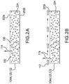
- Figures 2A-2B illustrate one embodiment of a possible mechanism for the reduction of volatile components from shaped prepregs and prepreg layups that employs a flow of a non-condensing gas adjacent the shaped prepreg and prepreg layups;
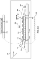
- Figures 3A-3C illustrate embodiments of enclosures that may be employed for the removal of volatile components from prepregs and prepreg layups and the manufacture of composite parts from these prepregs and layups.
- the phrase "at least a portion of" as used herein represents an amount of a whole amount that may range from less than the whole amount to up to and including the whole amount.
- the term “at least a portion of” may refer to an amount that is greater than 0.01% of, greater than 0.1% of, greater than 1% of, greater than 10% of, greater than 20% of, greater than 30% of, greater than 40% of, greater than 50% of, greater than 60%, greater than 70% of, greater than 80% of, greater than 90% of, greater than 95% of, greater than 99% of, and 100% of the whole.
- weight % or wt.% as used herein has its ordinary meaning as known to those skilled in the art.
- room temperature has its ordinary meaning as known to those skilled in the art and may include temperatures within the range of 16°C (60°F) to 38°C (100°F).
- Fiber as used herein has its ordinary meaning as known to those skilled in the art and may include one or more fibrous materials adapted for the reinforcement of composites. Fibers may take the form of particles, flakes, whiskers, short fibers, continuous fibers, filaments, tows, bundles, sheets, plies, and combinations thereof. Continuous fibers may further adopt any of unidirectional, multi-dimensional (e.g. two-or three-dimensional), non-woven, woven, knitted, stitched, wound, and braided configurations, as well as swirl mat, felt mat, and chopped mat structures.
- multi-dimensional e.g. two-or three-dimensional
- Woven fiber structures may comprise a plurality of woven tows having less than 1000 filaments, less than 3000 filaments, less than 6000 filaments, less than 12000 filaments, less than 24000 filaments, less than 48000 filaments, less than 56000 filaments, and less than 125000 filaments.
- the tows may be held in position by cross-tow stitches, weft-insertion knitting stitches, or a small amount of resin, such as a thermoplastic resin.
- the composition of the fibers may be varied, as necessary.
- Embodiments of the fiber composition may include, but are not limited to, glass, carbon, aramid, quartz, polyethylene, polyester, poly-p-phenylene-benzobisoxazole (PBO), boron, polyamide, , and graphite, silicon carbide, silicon nitride, Astroquaxtz®, Tyranno®, Nextel®, and Nicalon®, and combinations thereof.
- matrix may include one or more compounds comprising thermoset and/or thermoplastic materials.
- examples may include, but are not limited to, epoxies, epoxy curing agents, phenolics, phenols, cyanates, polyimides (e.g., imides, polyimides, bismaleimide (BMI), polyetherimides), polyesters, benzoxazines, polybenzoxazines, polybenzoxazones, polybenzimidazoles, polybenzothiazoles, amides, polyamides, esters, polyesters, polyamidimides, polysulphones, polyether sulphones, polycarbonates, polyethylene terepthalates, cyanates, and polyether ketones (e.g. polyether ketone (PEK), polyether ether ketone (PEEK), polyether ketone ketone (PEKK) and the like), combinations
- endcaps may include, but are not limited to, nadic and substituted nadic compounds such as nadic imide and allylnadicimide. ethynyl compounds and substituted ethynyl compounds, such as phenylethynyl and phthalic phenylethynyl compounds and olefuric compounds.
- Matrices may further comprise additives.
- additives may be provided to influence one or more of mechanical, rheological, electrical, optical, chemical, and/or thermal properties of the matrix.
- Such additives may further comprise materials that chemically react with the matrix or are unreactive with the matrix.
- the additives may be any combination of soluble, insoluble or partially soluble.
- the size distribution and geometry of such additives may also be varied, as necessary. For example, the size of the additives may range between nanoscale dimensions (1 nm-100 nm), microscale dimensions (100 nm-100 ⁇ m), and macroscale dimensions, greater than 100 ⁇ m.
- the additives may be configured in geometries including, but not limited to, particles, flakes, rods, fibers and the like.
- the additives may be distributed within a selected area of the matrix (e.g. adjacent a surface of the matrix or at the ply interfaces) or evenly distributed or dissolved within the matrix.
- examples of additives may include, but are not limited to, organic and inorganic substances such as thermoplastics, rubbers, nanorubbers, thermosets, flame retardants, ultraviolet (UV) protectors, thickeners (e.g., Cabosil®), and reinforcements to enhance one or more of strength, viscosity, damage tolerance, toughness, crack resistance wear resistance (e.g., rubbers, ceramics, and/or glasses).
- curing and “curing” as used herein have their ordinary meaning as known to those skilled in the art and may include polymerizing and/or cross-linking processes. Curing may be performed by processes that include, but are not limited to, heating, exposure to ultraviolet light, and exposure to radiation. In certain embodiments, curing may take place within the matrix. Prior to curing, the matrix may further comprise one or more compounds that are, at room temperature, liquid, semi-solid, crystalline solids, and combinations thereof. In further embodiments, the matrix within the prepreg may be formulated and/or partially cured in order to exhibit a selected stickiness or tack. In certain embodiments, consolidation and curing may be performed in a single process.
- solidation as used herein has its ordinary meaning as known to those skilled in the art and may include processes in which the resin or matrix material flows so as to displace void space within and adjacent fibers.
- “consolidation” may include, but is not limited to, flow of matrix into void spaces between and within fibers and prepregs, and the like.
- Consolidation may further take place under the action of one or more of heat, vacuum, and applied pressure.
- impregnation has its ordinary meaning as known to those skilled in the art and may include the introduction of a matrix material between or adjacent to one or more fibers.
- the matrix may take the form of films, powders, liquids, and combinations thereof. Impregnation may be facilitated by the application of one or more of heat, pressure, and solvents.
- prepreg has its ordinary meaning as known to those skilled in the art and may include one or more sheets of fibers that have been fully or partially impregnated with a matrix material.
- the matrix may also be present in a partially cured state.
- shaped prepreg has its ordinary meaning as known to those skilled in the art and may include prepregs that possess a selected geometric configuration.
- the selected geometric configuration may comprise planar geometries, curvature in one or more dimensions, and combinations thereof.
- a prepreg may be shaped by impregnation of a fiber preform having the selected geometric configuration.
- the prepreg may be deformed from a first geometric configuration to a second selected geometric configuration.
- the prepreg may possess sufficient integrity such that the shaped prepreg may maintain the selected geometric configuration after deformation without constraint.
- the prepreg may be deformed and constrained in place by one or more molds or other shaping devices.
- a shaped prepreg may comprise a prepreg that possesses sufficient drape so as to conform to at least a portion of a mold or other shaping device so as to adopt the selected geometric configuration.
- reduced volatile prepreg as used herein include shaped prepregs that have been exposed to a flow of non-condensing gas so as to remove a selected amount of volatile components from a shaped prepreg.
- reduced volatile prepregs may possess a concentration of volatile components less than 30 weight. %. In other embodiments, the reduced volatile prepreg may be less than 10 wt.%.
- prepreg layup and "shaped prepreg layup” as used herein have their ordinary meaning as known to those skilled in the art and may include a plurality of prepregs that are placed adjacent one another.
- the prepregs within the layup may be positioned in a selected orientation with respect to one another.
- prepreg layups may comprise prepregs having unidirectional fiber architectures, with the fibers oriented at 0°, 90°, or a selected angle ⁇ , and combinations thereof, with respect to a dimension of the layup, such as the length or width.
- prepregs having any combination of architectures may be combined to form the prepreg layup.
- a prepreg layup may be shaped by being placed on, in or adjacent to a mold or other constraining device. Further embodiments of a prepreg layup may include a plurality of shaped prepregs that are similarly placed adjacent one another.
- a prepreg layup may be stitched together with a threading material in order to inhibit the prepregs relative motion from a selected orientation.
- Prepreg layups may be manufactured by techniques including, but not limited to, hand layup, automated tape layup (ATL), advanced fiber placement (AFP), and filament winding, resin film infusion (RFI) or resin transfer molding (RTM).
- the prepreg layup or reduced volatile prepreg layup may further include other materials, non-limiting examples are honeycomb, foam core, or other materials, for example, metal stiffeners.
- reduced volatile layup and “reduced volatile prepreg layup” as used herein include shaped prepreg layups that have been exposed to a flow of non-condensing gas in an enclosure so as to remove a selected amount of volatile components from a shaped prepreg layup.
- reduced volatile prepreg layups may possess a concentration of volatile components less than 30 wt. %.
- Further embodiments of reduced volatile prepreg layups may include a prepreg layup comprising a plurality of reduced volatile prepregs.
- reduced volatile prepreg layup can be any combination of shaped prepregs, reduced volatile prepregs, layups, and/or reduced volatile layups where at least one has had the volatile components reduced by a flow of non-condensing gas described above.
- the reduced volatile prepreg layups after assembly can have the volatile components reduced further by the flow of non-condensing gas.
- volatile component and “volatiles” as used herein have their ordinary meaning as known to those skilled in the art and may include compounds that have a vapor pressure such that at least a portion of the volatile component may vaporize at temperatures up to 300°C.
- volatile component may include, but are not limited to gases dissolved within the matrix resin (e.g., air, nitrogen, oxygen, water), solvents including but not limited to alcohols, chlorated solvents, hydrocarbons, dimethylacetamide and N-methylpyrrolidone (NMP), and compounds produced by reaction such as, alcohols, organic acids, inorganic acids, water, and other volatile species
- Embodiments of the present disclosure provide methods for the removal of volatile components from shaped prepregs, prepreg layups and/or reduced volatile prepreg layups. Further embodiments of the present disclosure provide composites formed from reduced volatile prepregs and reduced volatile prepreg layups.
- one or more shaped prepregs, prepreg layups and/or reduced volatile layups are placed within an enclosure and a non-condensing gas is introduced into and removed from the enclosure simultaneously or sequentially, adjacent at least one surface of the shaped prepreg, prepreg layup and/or reduced volatile layup.
- one of heat, pressure and/or vacuum may be applied to facilitate volatile removal.
- suitable non-condensing gases may include, but are not limited to air, nitrogen, oxygen, neon, argon, methane, ethane, ethylene, propane, hydrogen, helium, and combinations thereof.
- the flow of the non-condensing gas assists in the removal of volatile components, such as solvents, from the shaped prepreg, prepreg layups or reduced volatile prepreg layups by at least increasing the rate and/or the completeness at which volatile components are removed.
- shaped prepregs, prepreg layups or reduced volatile layups may be subjected to heat, pressure, vacuum, and combinations thereof, to further assist the evolution and removal of the volatile components.
- Combinations of shaped prepregs, reduced volatile prepreg layups, reduced volatile prepregs, and prepreg layups where at least one is reduced volatile as described may be further subjected to heat, with pressure and/or vacuum, to form composite structures.
- the loss of matrix resin from the shaped prepreg or prepreg layups, e.g., bleed, that occurs when removing volatile components may be reduced using a flow of non-condensing gas.
- Ancillary effects associated with excessive bleed, such as blockage of matrix passageways and gas flow, may also be ameliorated by use of a flow of non-condensing gas to remove volatile components from shaped prepregs, prepreg layups and reduced volatile prepreg layups. For example, in certain embodiments, 0 to 30 wt.
- % of the matrix solids may bleed when fabricating reduced volatile prepregs or reduced volatile prepreg layups according to the disclosed embodiments.
- the flow of non-condensing gas may increase the rate or the completeness of removal of volatile components, such as solvents, from the shaped prepregs prepreg layups or reduced volatile prepreg layups..
- removal of volatiles may cause the matrix viscosity to increase at a faster rate than would be achieved absent the flow of non-condensing gas, inhibiting the flow of the matrix from the shaped prepregs, prepreg layups or reduced volatile prepreg layups.
- removal of the volatile components may cause the matrix resin components to form crystals which may further inhibit bleed and may promote ply to ply volatile transport.
- the matrix resin components may further inhibit bleed and may promote ply to ply volatile transport.
- the use of a flow of non condensing gas to remove volatile components from shaped prepregs,prepreg layups or reduced volatile layups may inhibit the development of misaligned fibers in the composite part.
- the fibers are generally aligned in selected orientations for strength.
- the amount of excess gas that builds up within the shaped prepreg, prepreg layup or reduced volatile layup. during volatile reduction, consolidation, and/or cure may be greatly reduced, reducing the likelihood of fiber displacement during consolidation and cure.
- fiber displacement may be quantified by an angle at which a unidirectional fiber or a continuous fiber of a woven fiber structure is positioned with respect to a selected direction. For example, a properly aligned fiber would demonstrate an angle of 0° with respect to a selected direction.
- fiber displacement may be characterized by microscopy.
- a flow of non-condensing gas to remove volatile components from a shaped prepreg, prepreg layup or reduced volatile layup may simplify the fabrication process.
- a shaped prepreg, prepreg layup or reduced volatile layup may be subjected to a flow of a non-condensing gas in combination with heat pressure and/or vacuum so as to urge volatile components within the matrices of the shaped prepreg, reduced volatile prepreg layup or prepreg layup to enter the gas phase, evolve from the shaped prepreg, reduced volatile prepreg or prepreg layup, and be transported away from the shaped prepreg or and prepreg layup.
- one such operation may remove a comparable amount of volatile content as may be achieved by application of heat and pressure alone but at a faster rate or to a higher completeness.
- the use of a flow of non-condensing gas to remove volatile components from a shaped prepreg or prepreg layup may enable the fabrication of larger, more complex composites than has been traditionally possible.
- the size of a composite part is increased, the volume of matrix material within a shaped prepreg, prepreg layup or reduced volatile layup used to form the composite part is also increased, resulting in greater matrix bleed from the shaped prepreg, prepreg layup or reduced volatile layup, as compared with smaller composite parts.
- significantly more time is necessary to remove volatile components from prepreg layups for large composite parts, as compared with smaller composite parts.
- the amount of matrix bleed exhibited by the shaped prepreg, prepreg layup or reduced volatile layup, and/or the time necessary to remove volatile components from the shaped prepreg, prepreg layup or reduced volatile layup may be reduced, facilitating the fabrication of large composite parts and reducing porosity and/or bleed.
- Figures 1A-1I illustrate a embodiments of a method of manufacturing reduced volatile prepregs, reduced volatile prepreg layups, and composites formed using these reduced volatile prepregs and reduced volatile prepreg layups.
- the method of Figures 1A-1I may include fewer or additional steps and the steps may be performed in a different order, as necessary, without departing from the scope of the disclosed embodiments.
- prepregs 104 may be manufactured by impregnation of a matrix 100, in the form of solids, semi-solid films, powders, and liquids, into fibers 102, with or without application of heat pressure and/or vacuum.
- the impregnation may be performed using a number of techniques including, but not limited to, solution processes, such as solution dip and solution spray, melt and working processes, such as direct melt and film calendaring, and resin transfer (RTM), vacuum-assisted resin transfer (VARTM) or resin film infusion (RFI).
- tack of the prepreg may be adjusted accordingly during and/or after matrix impregnation by the solvent content of the matrix resin.
- the fibers 102 may be passed through a bath of matrix solids that are dissolved within a solvent. As the fibers 102 pass through the bath, they pick up an amount of matrix solids that varies with factors such as the speed at which the fibers 102 are passed through the bath and the concentration of matrix solids within the bath. In solution spray processes, a selected amount of matrix solids are sprayed upon the fiber 102. In each case of solution processing, the impregnated fiber 102 may be heated after exposure to the bath or spray in order to adjust the solvent content and adjust, for example, handling of the prepreg.
- the matrix 100 is provided as a coating directly upon the fiber 102 at an elevated temperature. At the temperature of application, the matrix 100 is sufficiently flowable so as to impregnate at least a portion of the fibers 102.
- the matrix 100 is cast into a film from melt or solution. The fiber 102 is subsequently sandwiched between one or more matrix films and calendared so as to work the matrix film into the fiber 102.
- the impregnated fiber 102 may be heated and/or solvent may be added in order to adjust the solvent content and adjust, for example, the flexibility of the prepreg.
- the matrix 100 is injected into a mold or mold that contains the fibers 102.
- the fibers 102 are provided as a dry fiber preform or a pre-impregnated preform with less than the desired amount of matrix 100.
- the matrix 100 is then introduced into the mold with or without a carrier solvent. Under the influence of gravity, pressure, and capillary action (RTM) or gravity, capillary action, and vacuum (VARTM), the matrix 100 enters the fibers 102.
- RTM capillary action
- VARTM vacuum
- a film is used to provide the resin and typically placed adjacent to the fibers such as in a mold or vacuum bag.
- the fiber content of the prepreg 104 may be varied, as dictated by the application.
- the weight fraction of fiber 102 may range between 20 to 80 wt.%, on the basis of the total weight of the prepreg 104.
- the content and composition of the matrix 100 within the prepreg 104 may also be varied, as necessary.
- the matrix solids within the prepreg 104 may range between 20 to 80 wt.%, based upon the total weight of the prepreg 104.
- multiple solvents may be advantageous.
- a non-limiting example is a mixture of methanol and propanol where the different boiling points provide a more controllable evolution of volatile species making the shaped prepreg, prepreg layup and/or reduced volatile layup less suseptable to ply and fiber movement.
- Another non-limiting example is a mixture of 3 or 4 solvents.
- the matrix 100 may further comprise one or more carrier solvents that reduce the viscosity of the matrix 100, facilitating impregnation and handling of the prepreg.
- carrier solvents may include, but are not limited to, alcohols, chlorinated solvents, hydrocarbons N-methylpyrrolidone (NMP) and dimethylacetamide.
- the solvent is present within the prepreg 104 in a concentration of 1 to 60 weight % on the basis of the total weight of the prepreg 104.
- a prepreg 104 may be shaped by impregnation of a fiber preform having a selected geometric configuration.
- the selected geometric configuration may comprise planar geometries, curvature in one or more dimensions, and combinations thereof.
- the prepreg 104 may be deformed from a first geometry to a second, selected geometry.
- the prepreg 104 may possess sufficient integrity such that the prepreg may maintain the selected geometric configuration after deformation without constraint.
- the prepreg 104 may be constrained in place by a mold 116 or other shaping device.
- the mold 116 may further comprise texture and/or other surface and through thickness features, as necessary.
- a shaped prepreg may comprise prepregs that possess sufficient drape so as to conform to at least a portion of a mold or other shaping device so as to adopt the selected configuration.
- shaped prepreg 104A may be placed within an enclosure 110 for example, a vacuum bag, or oven or press and exposed to a flow of non-condensing gas 112 for the removal of at least a portion of their volatile components 114 to form a reduced volatile prepreg 106.
- prepreg 104 may be shaped by placement of at least a portion of prepregs 104 adjacent to, or in contact with, mold 116 while exposed to a flow of non-condensing gas 112.
- shaped prepregs 104A are added to an enclosure 110 for volatile reduction as in Figure 1D .
- shaped prepreg 104A may be prepared within the enclosure 110.
- a dry shaped fiber preform may be introduced into the enclosure 110 and impregnated with the matrix 100 to form shaped prepreg 104A.
- shaped prepreg 104A may contain less than a selected amount of matrix 100 and may be further impregnated with additional matrix 100 within mold 116 to form shaped prepreg 104A.
- the flow of non-condensing gas 112 may be injected and removed from the enclosure 110 in order to reduce the volatile components 114 content from shaped prepreg 104A and yield reduced volatile prepreg 106 as in Figure 1D .
- the non-condensing gas 112 may be introduced into and removed from the enclosure 110 containing shaped prepreg 104A, at a selected rate for a selected of time period, in order to yield reduced volatile prepreg 106 having a concentration of volatile components that is less than that of shaped prepreg 104A.
- the non-condensing gas 112 may be allowed to flow adjacent to at least one surface of shaped prepreg 104A at a selected rate for a selected time, yielding reduced volatile prepreg 106 having a concentration of volatile components that is less than that of shaped prepreg 104A.
- the non-condensing gas 112 may comprise gaseous species including, but not limited to, air, oxygen, nitrogen, neon, argon, methane, ethane, ethylene, propane, hydrogen, helium, and combinations thereof.
- non-condensing gas 112 is introduced and removed from enclosure 110 continuously.
- the inlet and outlet for addition and removal of the non-condensing gas 112 from the enclosure 110 may be the same or different, as necessary.
- Reduced volatile prepreg 106 so formed may be employed to form reduced volatile prepreg layups 122.
- one or more reduced volatile prepregs 106 may be stacked to form the reduced volatile prepreg layup 122 ( Figure 1E ).
- the reduced volatile prepreg layup 122 may comprise one or more reduced volatile prepregs 106 and/or reduced volatile prepreg layup 122 and/or shaped prepregs 104A and/or prepreg layups 120 ( Figure 1E ).
- reduced volatile prepreg layup 122 may be comprised entirely of a plurality of reduced volatile prepregs 106. In the above embodiment in Fig.
- the volatile reduction operation is optional as long as at least one is a reduced volatile prepreg 106 or reduced volatile layup 122.
- reduced volatile prepreg layups 122 are formed by performing the volatile reduction operations discussed above upon prepreg layups 120, rather than any combinations as discussed above. In such case, the volatile reduction process must be employed to produce reduced volatile prepreg layup 122.
- the volatile reduction process discussed above with respect to shaped prepreg 104A may be performed upon reduced volatile prepreg 106 or reduced volatile prepreg layup 122, alone or in combination with shaped prepreg 104A or prepreg layup 120, without limit.
- reduced volatile prepreg 106 and reduced volatile prepreg layup 122 may be repeatedly subjected to volatile reduction by exposure to a flow of non-condensing gas 112 in order to obtain a selected volatile content.
- the amount of volatile components removed from shaped prepreg 104A or shaped prepreg layup 120 or reduced volatile layup 122 in the volatile reduction process may be varied, as necessary.
- the reduced volatile prepreg and reduced volatile prepreg layup 106, 122 may comprise 0-99% of the volatile components contained within the shaped prepreg 104A, prepreg layups 120 or reduced volatile layups 122.. That is to say, 1-100% of the volatile content within the shaped prepreg 104A shaped prepreg layups 120 or reduced volatile prepreg layup 122 may be removed in formation of the reduced volatile prepregs106 and reduced volatile prepreg layup 122.
- the viscosity of the matrix in reduced volatile prepregs 106 and reduced volatile prepreg layups, 122, after removal of a selected amount of volatile components is higher than in the shaped prepreg 104A, prepreg layup 120 or reduced prepreg volatile layup 122 before volatile reduction.
- some of the components of the reduced volatile prepregs 106 or reduced volatile layups 122 may crystallize which may promote, for example, ply to ply volatile movement.
- pores, holes or penetrations may be introduced into the prepregs 104, shaped prepregs 104A, prepreg layups 120 reduced volatile prepregs 106 and/or reduced layups 122 to promote ply to ply volatile movement larger than 0.1mm or smaller than 20mm.
- gases 114 such as volatilized solvents and/or other volatilized reaction products, that travel through the interior 204 of the shaped prepreg and shaped prepreg layup 104A, 120 to their exterior surfaces, such as exterior surfaces 202A, illustrated in Figure 2A .
- the flow of non-condensing gas 112 adjacent at least one exterior surface of the shaped prepreg 104A or prepreg layup 120, or reduced volatile layup 122 such as exterior surface 202A urges the evolved gases 114 away from the shaped prepreg, 104A, prepreg layup, 120 or reduced volatile layup 122 and out of the enclosure 110.
- Reduced volatile prepregs and reduced volatile prepreg layups 106, 122 so formed may possess a selected amount of solvents and other volatiles that facilitate processing of the composite part 124.
- the solvent content of a shaped prepreg ranges between 1 to 50 wt. %, for example, 15 wt. %, based on the total weight of the shaped prepreg 104A.
- the solvent content of a reduced volatile prepreg 106 ranges between 0 to 40 wt. %, for example, less than 10 wt. %, based upon the total weight of the reduced volatile prepreg 106.
- the viscosity of the matrix within shaped prepreg 104A is also lower than the viscosity of the matrix within reduced volatile prepreg 106 or reduced volatile prepreg layup 122.
- the flow rate of the continuous flow of the non-condensing gas 112 ranges between 0.001 to 1000 ml/s.
- Figures 3A-3C illustrate an embodiment of the enclosure 110 in greater detail.
- the enclosure 110 may be configured to provide heat 300, pressure 302, vacuum, and combinations thereof to the enclosure 110.
- heat 300, pressure 302, and/or vacuum may be provided to the enclosure 110 before, during, and/or after introduction of the flow of non-condensing gas 112 in order to facilitate the removal of volatile components from a shaped prepreg 104A or prepreg layup 120.
- the enclosure 110 may also be employed to provide any combination of heat 300, pressure 302, and vacuum in order to facilitate consolidation and curing of devolatilized prepreg 105 prepreg layups 122 into composite parts 124, as illustrated in Figures 1E-1F .
- the enclosure 110 may comprise a structure capable of applying at least one of heat 300, pressure 302, and vacuum to a shaped prepreg 104A, a reduced volatile prepreg 106 a prepreg layup 120, or a reduced volatile prepreg layup 122 undergoing volatile reduction, such as ovens and autoclaves.
- the enclosure 110 may be configured for placement into a device capable of adding heat, vacuum and/or pressure, for example, an oven, autoclave and/or press.
- the flow of non-condensing gas 112 may be introduced to the shaped prepreg 104A, reduced volatile prepreg106 or prepreg layup 120, or reduced volatile layup 122 in an oven to yield a reduced volatile prepreg or reduced volatile layup 106, 122, respectively.
- the reduced volatile prepreg or reduced volatile layup 106, 122 may be transferred to an autoclave or press for consolidation and cure to form a composite part 124.
- a reduced volatile prepreg or reduced volatile prepreg layup 106, 122 respectively may be manufactured in an autoclave or press under pressure.
- the final temperature may depend on the composition of the shaped prepreg 104A, reduced volatile prepreg106, prepreg layup 120, or reduced volatile layup 122 and may further comprise a temperature which is equal to the boiling point of at least one solvent within the matrix 100.
- the temperature may equal 88°C (190°F) to 110°C (230°F).
- the temperature may comprise at temperature that is greater than 70%, greater than 75%, greater than 80%, greater than 85%, greater than 90%, or greater than 95% of the boiling point of at least one solvent of the matrix 100.
- the heating rate may range between 0.01 to 5°C/min.
- the final temperature and/or heating rate with respect to the boiling point of solvents within the matrix 100, boiling or rapid evolution of the solvents and volatiles, resulting in displacement of fibers 102, may be inhibited.
- enclosure 110 may be capable of applying and/or supporting an applied vacuum.
- enclosure 110 may further comprise a vacuum envelope or vacuum bag 306 well known in the art that forms an gas-tight region in which shaped prepreg 104A, reduced volatile prepreg106, prepreg layup 120, or reduced volatile layup 122 may be placed.
- the applied vacuum may be provided by a vacuum source in communication with a gas vent 304 of the enclosure 110.
- the applied vacuum may further be varied or kept constant while volatile components are removed from the shaped prepreg 104A, reduced volatile prepreg106, prepreg layup 120, or reduced volatile layup 122.
- a vacuum of 133 Pa (1 mm Hg) or less may be supported by the vacuum envelope 306.
- a vacuum of 46.7 to 100 kPa (350 to 750 mm Hg) may be used during the flow of non-condensing gas. In other embodiments the vacuum may be lower.
- enclosure 110 may be capable of applying and/or supporting a pressure 302.
- the applied pressure 302 may be provided by a pressure source in communication with enclosure 110.
- the applied pressure 302 may further be varied or kept constant while volatile components are reduced from shaped prepreg 104A, reduced volatile prepreg106, prepreg layup 120, or reduced volatile layup 122.
- a pressure ranging atmospheric pressure up to 27579 kPa (4000 psi) may be applied.
- enclosure 110 may comprise one or more structures capable of inhibiting flow of the matrix 100 from shaped prepregs 104A, reduced volatile prepreg106, prepreg layup 120, or reduced volatile layup 122 during volatile reduction and consolidation.
- dams 314 may be positioned adjacent the sides of shaped prepreg 104A, reduced volatile prepreg106, prepreg layup 120, or reduced volatile layup 122 so as to inhibit flow of the matrix from the sides of the shaped prepreg 104A, reduced volatile prepreg106, prepreg layup 120, or reduced volatile layup 122.
- bleed barriers or separators 322 may be placed adjacent at least one of upper and lower surfaces of the shaped prepreg 104A, reduced volatile prepreg106, prepreg layup 120, or reduced volatile layup 122 so as to inhibit flow of the matrix from the upper and lower surfaces of the shaped prepreg 104A, reduced volatile prepreg106, prepreg layup 120, or reduced volatile layup 122.
- the flow of non-condensing gas 112 may be injected into enclosure 110 through a gas inlet 310 and removed from the enclosure from a gas vent 304 containing shaped prepreg 104A, reduced volatile prepreg106, prepreg layup 120, or reduced volatile layup 122.
- the gas vent 304 may be in fluid communication with a vacuum source such that a vacuum may be exerted on shaped prepreg 104A, reduced volatile prepreg106, prepreg layup 120, or reduced volatile layup 122.
- the gas inlet 310 may be positioned such that shaped prepreg 104A, reduced volatile prepreg106, prepreg layup 120, or reduced volatile layup 122 are interposed between the gas inlet 310 and the vent to vacuum 304, as illustrated in Figure 3A .
- This configuration enables a vacuum exerted by the vacuum source to urge the non-condensing gas 112 to follow a path, from the gas inlet 310 to the gas vent 304, that passes adjacent at least one surface of the shaped prepreg 104A, reduced volatile prepreg106, prepreg layup 120, or reduced volatile layup 122.
- the non-condensing gas 112 may be injected and removed from the enclosure 110 at the same location.
- Non-condensing gas 112 may be injected and/or removed from enclosure 110 in a variety of ways. In one embodiment, injection and removal of non-condensing gas 112 from enclosure 110 may be performed concurrently and continuously. In another embodiment, injection and removal of non-condensing gas 112 from enclosure 110 may be performed sequentially, or stepwise. For example, non-condensing gas 112 may be first introduced into enclosure 110 and, subsequently, enclosure 112 may be vented to remove the non-condensing gas from enclosure 110.
- enclosure 110 may comprise one or more structures that enable flow of non-condensing gas 112 adjacent shaped prepreg 104A, reduced volatile prepreg106, prepreg layup 120, or reduced volatile layup 122.
- molds 116, 116A may possess a plurality of purge holes 312, as illustrated in Figure 3A .
- the purge holes 312 may comprise conduits through the molds 116, 116A that allow the transport of gases, such as evolved gases 114 and the non-condensing gas 112, through the molds 116, 116A.
- Purge holes 312 may be further oriented perpendicular to, and/or parallel to, the plane of shaped prepreg 104A, reduced volatile prepreg106, prepreg layup 120, or reduced volatile layup 122. Beneficially then, even when one or more of molds 116, 116A contact the outer surfaces of the shaped prepreg 104A, reduced volatile prepreg106, prepreg layup 120, or reduced volatile layup 122, the plurality of purge holes 312 allow the non-condensing gas 112 and the evolved gases 114 to move adjacent the outer surfaces of the shaped prepreg 104A, reduced volatile prepreg106, prepreg layup 120, or reduced volatile layup 122, facilitating removal of the volatile components from shaped prepreg 104A, reduced volatile prepreg106, prepreg layup 120, or reduced volatile layup 122.
- an optional breather 330 may be placed between the bleed barrier or separator 322 and the vacuum envelope 306.
- the flow on non-condensing gas may be through this breather.
- the breather may be fiberglass, polyester, polyester pile and the like.
- vacuum envelope 306 may be omitted from enclosure 110.
- the flow of non-condensing gas 112 may enter and exit enclosure 110 through a gas inlet 310A and gas vent 310B within the walls of enclosure 110.
- the gas inlet 310A and gas vent 310B may be positioned such that shaped prepreg 104A, reduced volatile prepreg106, prepreg layup 120, or reduced volatile layup 122 are interposed between gas inlet 310A and gas vent 310B.
- the pressure gradient between gas inlet 310A and gas vent 310B may urge the non-condensing gas 112 to follow a path that runs adjacent at least one surface of shaped prepreg 104A, reduced volatile prepreg106, prepreg layup 120, or reduced volatile layup 122, transporting evolved gases 114 away from shaped prepreg 104A, reduced volatile prepreg106, prepreg layup 120, or reduced volatile layup 122 and increasing the rate and/or the completeness of removal of volatile components from shaped prepreg 104A, reduced volatile prepreg106, prepreg layup 120, or reduced volatile layup 122.
- the gas inlet 310A and gas vent 310B may be combined and the operations of injecting the non-condensing gas into and removing the non-condensing gas 112 from within the enclosure 110 may be performed sequentially.
- shaped prepreg 104A, reduced volatile prepreg106, prepreg layup 120, or reduced volatile layup 122 may be further molded without a cavity.
- shaped prepreg 104A, reduced volatile prepreg106, prepreg layup 120, or reduced volatile layup 122 may be covered with a permeable mold separator or bleed barrier 322, where there is no resistance to evolved gases 114 escaping the surface of shaped prepreg 104A, reduced volatile prepreg106, prepreg layup 120, or reduced volatile layup 122.
- This configuration may further employ weights, springs, tensioning belts, or other mechanisms if shaped prepreg 104A, reduced volatile prepreg106, prepreg layup 120, or reduced volatile layup 122 possess curvature.
- Shaped prepreg 104A, reduced volatile prepreg106, prepreg layup 120, or reduced volatile layup 122 may then be placed in an oven and heated. The gases and volatiles are readily removed by the rapid diffusion away from shaped prepreg 104A, reduced volatile prepreg106, prepreg layup 120, or reduced volatile layup 122.
- the devolatilized prepregs and devolatilized layups 106, 122 may then be transferred to a press, vacuum enclosure or envelope or autoclave for consolidation and/or curing to form the composite part.
- a press, vacuum enclosure or envelope or autoclave for consolidation and/or curing to form the composite part.
- Such an embodiment may be advantageous in circumstances where shaped prepregs 104A, reduced volatile prepreg106, prepreg layup 120, or reduced volatile layup 122 are added to prepreg layups 120, 122 during volatile reduction in multiple stages.
- Figure 3C , shaped prepreg 104A, reduced volatile prepreg106, prepreg layup 120, or reduced volatile layup 122 may be further combined with a plurality of cores 320 formed of foam, honeycomb, or other materials.
- the cores 320 may be positioned adjacent the prepregs 104A, 106 before or during removal of volatile components from the shaped prepreg 104A, reduced volatile prepreg106, prepreg layup 120, or reduced volatile layup 122.
- the cores 320 may be positioned adjacent to one side of one or more shaped prepregs 104A, reduced volatile prepreg106, prepreg layup 120, or reduced volatile layup 122.
- the cores 320 may be positioned between adjacent prepregs 104, 106.
- Volatile components may be removed from shaped prepreg 104A, reduced volatile prepreg106, prepreg layup 120, or reduced volatile layup 122 with cores 320 in a manner similar to that discussed above.
- shaped prepreg 104A, reduced volatile prepreg106, prepreg layup 120, or reduced volatile layup 122, molds 116, and cores 320 may be placed within a vacuum envelope 306.
- the vacuum envelope 306 may be omitted.
- the flow of non-condensing gas 112 is injected within the enclosure 110 and flows adjacent the surfaces of the molds 116, cores 320, shaped prepreg 104A, reduced volatile prepreg106, prepreg layup 120, or reduced volatile layup 122, and combinations thereof.
- Volatile components within shaped prepreg 104A, reduced volatile prepreg106, prepreg layup 120, or reduced volatile layup 122 may evolve gases 114 spontaneously or upon exposure to heat 300, pressure 302, and/or vacuum, and travel through shaped prepreg 104A, reduced volatile prepreg106, prepreg layup 120, or reduced volatile layup 122, molds 116, and/or cores 320.
- Molds 116 and cores 320 may further assist in the reducing the of volatile components in the shaped prepreg 104A, reduced volatile prepreg106, prepreg layup 120, or reduced volatile layup 122 and containment of the matrix 100.
- the molds 116 and cores 320 may function in a manner similar to the bleed barrier or seperator or 322.
- the molds 116 and cores 320 may function similarly to a breather layer, maintaining a path throughout the vacuum envelope 306 to the vacuum source. This path enables the non-condensing gas 112 and evolved gases 114 to be removed from the vacuum envelope 306 without being slowed by obstacles that might be otherwise present absent the path.
- the path further enables an continuous vacuum and/or pressure 302 to be applied to the shaped prepreg 104A, reduced volatile prepreg106, prepreg layup 120, or reduced volatile layup 122.
- the process of reducing volatile component shaped prepreg 104A, reduced volatile prepreg106, prepreg layup 120, or reduced volatile layup 122 may be interrupted and/or restarted at any time.
- one or more of the shaped prepregs 104A, reduced volatile prepreg106, prepreg layup 120, or reduced volatile layup 122 may be placed within the enclosure 110 for volatile component removal using the flow of non-condensing gas 112, as discussed above and the volatile removal process may be interrupted prior to the removal of a desired amount of volatile components from shaped prepreg 104A, reduced volatile prepreg106, prepreg layup 120, or reduced volatile layup 122.
- additional prepregs 104A, reduced volatile prepreg106, prepreg layup 120, or reduced volatile layup 122 may be added to those already present within the enclosure and the devolatilization process may be restarted.
- reduced volatile prepregs 106 or reduced volatile prepreg layups 122 may be employed to form the composite part 124.
- the consolidation process may employ at least one of heat, pressure, and vacuum in order to urge the matrix 100 to flow into at least a portion of the void space that is located within and between reduced volatile prepreg 106 or the reduced volatile layup 122.
- reduced volatile prepreg 106 or reduced volatile prepreg layup 122 may be subjected to heat 300, vacuum, and/or pressure 302 to consolidate the reduced volatile prepreg 106 or reduced volatile prepreg layup 122 into the composite part 124, and cure the matrix 102.
- the reduced volatile prepreg 106 or reduced volatile prepreg layup 122 may be subjected to heat, without pressure, to consolidate the reduced volatile prepreg 106 or reduced volatile prepreg layup 122 into the composite part 124 and cure the matrix 102.
- the reduced volatile prepreg layup 122 may be subjected to vacuum and/or heat to consolidate the reduced volatile prepreg 106 or reduced volatile prepreg layup 122 into the composite part 124.
- reduced volatile prepreg 106 or reduced volatile prepreg layup 122 may be further molded and/or compression molded using the molds 116, 116A to consolidate reduced volatile prepreg 105 or reduced volatile prepreg layup 122 into composite part 124.
- composite part 124 formed may possess a porosity ranging between 0 to 30 vol.% on the basis of the total volume of the composite.
- the volatile reducing processes discussed herein may be further employed to facilitate adhesive bonding.
- Adhesives such as polyimide resin adhesives, may comprise alcohols and higher boiling solvents, for example, NMP.
- Adhesives may further comprise a carrier, for example, fiberglass, or Astroquartz®.
- Adhesives may be placed between cured or uncured components, for example, composite parts 124, and/or honeycomb or foam core to form an assembly.
- the assembly enclosed may have the capability of adding at least one of vacuum pressure or heat. By exposing the component/adhesive system to a flow of non-condensing gas adjacent the interface between the components, or through the assembly enclosed with subsequent consolidation and cure as described herein, may reduce the interface porosity.
- Example 1- Carbon fiber/polyimide composites fabricated with and without non-condensing gas flow
- Three carbon fiber/epoxy composites Trial 1, Trial 2, and Trial 3, were fabricated from shaped prepreg layups in an enclosure dipicted in Figure 3A using the optional breather.
- the shaped prepreg layups of Trial 2 and Trial 3 were subjected to a flow of non-condensing gas, in combination with heat and vacuum pressure, to facilitate removal of volatile components from the shaped prepreg layups.
- the shaped prepreg layup of Trial 1 was not subjected to the flow of non-condensing gas.
- the reduced volatile layups were cured using a combination of heat, vacuum, and pressure.
- the composite part of Trial 1 was fabricated from prepregs comprising T650-35 6K 5HS carbon fiber fabric.
- the matrix resin comprising a polyimide resin mixture which contained 20% ethanol solvent and a resin solid content of 80% was impregnated into the fabric such that the matrix weight fraction of the prepregs was 60 wt. %.
- the prepregs were cut into sheets of 180 cm x 180 cm (6" by 6") and eight prepregs were stacked to form a 0/90 prepreg layup.
- the prepreg layup was surrounded by a dam and overlaid with two plies of TX-1080 Teflon separator and polyester fiber breather and was connected to a vacuum source
- Heat and vacuum were further applied to the assembly for volatile reduction.
- the applied vacuum level was 98 kPa (735 mm Hg) absolute and the assembly was heated at 2.8°C/minute (5°F/minute) to 87.8°C (190°F). Subsequently, the assembly was further heated at 0.05°C/minute (0.1°F/minute) to 98.9°C (210°F) and cooled to room temperature.
- the dam was removed and the polyester breather was replaced by 3 plies of 7781 style fiberglass.
- the assembly containing the reduced volatile layup was then cured as follows:
- the composite part of Trial 2 was manufactured in a similar manner as Trial 1, with the exception that a stream of air at 300 mL/min was passed through the vacuum envelope during the volatile reduction operation. Examination of the composite formed in Trial 2 found the composite to have 0% porosity and no resin bleed had taken place during manufacture.
- the composite part of Trial 3 was manufactured in a similar manner as Trial 2, except that the vacuum envelope comprised a non-polyester, 7781 fiberglass breather.
- the composite part in addition to the 7781 breather, was heated from room temperature to 87.8°C (190°F) at 2.8°C/min (5°F/min), and then to 98.9°C (210°F) at 0.05°C/min (0.1°F/minute).
- the flow of air was maintained at 300 mL/min. until the end of the period during which the temperature was held at 98.9°C (210°F).
- Tests 4 and 5 Two carbon fiber/epoxy composites, Tests 4 and 5, were fabricated under the same layup assembly and cure conditions as discussed above in Example 1. However, tests 4 and 5 were performed with a larger number of prepreg layers in the prepreg layup, larger sized prepreg layers, and the layup and consolidation were performed upon a large, complex mold. It was observed that parts formed with the flow of non condensing gas, in Trial 5, exhibited no bleed or resin loss, while parts formed without the flow of non-condensing gas, Trial 4, exhibited 16 wt. % resin loss. Table 2 - Test Parameters and results of Example 2 Trial Experiment Resin System Non-condensing gas flow? Bleed (wt. %) 4 Large curved part Polyimide No 16% 5 Large curved part Polyimide Yes 0%
- the composite part of Trial 4 was manufactured in a manner similar to Trial 1, except with a larger ply size and greater quantity, and on a larger, more complicated mold.
- 15 prepreg layers were cut to 5 cm x 5 cm (2'x2'), laid up upon a semi-circular cylinder, 16 inches in diameter and volatiles were reduced.
- a vacuum of 16.7 kPa 125 mm Hg was applied.
- Examination of the prepreg layup formed in Trial 4 after volatile reduction found that the layup had bled excessively, losing 16% of its matrix resin, by weight.
- the composite part of Trial 5 was manufactured in a manner similar to Trial 4, Trial 2 with the exceptions noted in and with different ply size and quantity, and on a larger, more complicated mold.
- 15 layers of prepreg were cut to 5 cm x 5 cm (2'x2'), laid up upon a semi-circular cylinder with downs and the volatiles reduced using a gas flow 5 liters/min.
- the dam material was removed and the part was consolidated and cured as described in Trial 1/.
- Examination of the composite formed in Trial 5 found the composite to have 0% porosity and no resin bleed had taken place during manufacture.
- Example 3 Carbon fiber/polyimide composites containing ethanol and NMP (Avimid RB) fabricated with and without non-condensing gas flow
- Example 3 demonstrates the use of an air stream on a multi-solvent system to reduce resin bleed.
- Two carbon fiber/epoxy composites, Trials 6 and 7, were fabricated under the assembly and cure conditions as in Trial 1 and Trial 2 in Example 1, employing Avimid RB polyimide prepreg, T650-35 6K 5HS.
- Avimid RB prepreg comprises 8% ethanol by weight and 8% NMP by weight, with a matrix weight fraction of 60%. It was observed that parts formed with the flow of non condensing gas in Trial 6, exhibited relatively low bleed, 1.9 wt. %, while parts formed without the flow of non-condensing gas, Trial 7, exhibited 12.6 wt. % resin loss.
- Trial 6 evaluated bleed using Avimid RB polyimide prepreg T650-35 6K 5HS.
- the prepreg layup assembly was done in a manner similar to that of Trial 1.
- An air stream at 300 ml/min was passed through the vacuum envelope during the volatile reduction operation. Initially, heat was added at 0.3°C/minute (0.5°F/minute) from 87.8°C (190°F) to 98.9°C (210°F). Heat was then added at 0.5°C/minute (1°F/minute) to 260°C (500°F) to drive off the NMP. Examination of the composite formed in trial 6 found that 1.9 wt.% of resin had bled during manufacture.
- Trial 7 was performed similarly to Test 6, except without the use of an air stream. Examination of the composite formed in Trial 7 found that 12.6 wt.% of resin had bled during manufacture.
Landscapes
- Chemical & Material Sciences (AREA)
- Engineering & Computer Science (AREA)
- Materials Engineering (AREA)
- Mechanical Engineering (AREA)
- Composite Materials (AREA)
- Health & Medical Sciences (AREA)
- Manufacturing & Machinery (AREA)
- Chemical Kinetics & Catalysis (AREA)
- Medicinal Chemistry (AREA)
- Polymers & Plastics (AREA)
- Organic Chemistry (AREA)
- Inorganic Chemistry (AREA)
- Reinforced Plastic Materials (AREA)
- Moulding By Coating Moulds (AREA)
- Casting Or Compression Moulding Of Plastics Or The Like (AREA)
Applications Claiming Priority (2)
| Application Number | Priority Date | Filing Date | Title |
|---|---|---|---|
| US10746208P | 2008-10-22 | 2008-10-22 | |
| PCT/US2009/061242 WO2010048122A1 (en) | 2008-10-22 | 2009-10-20 | Improved processing of polymer matrix composites |
Publications (2)
| Publication Number | Publication Date |
|---|---|
| EP2337672A1 EP2337672A1 (en) | 2011-06-29 |
| EP2337672B1 true EP2337672B1 (en) | 2018-02-28 |
Family
ID=41416204
Family Applications (1)
| Application Number | Title | Priority Date | Filing Date |
|---|---|---|---|
| EP09744271.9A Active EP2337672B1 (en) | 2008-10-22 | 2009-10-20 | Improved processing of polymer matrix composites |
Country Status (11)
| Country | Link |
|---|---|
| US (1) | US9186851B2 (ja) |
| EP (1) | EP2337672B1 (ja) |
| JP (1) | JP5649582B2 (ja) |
| KR (1) | KR101680393B1 (ja) |
| CN (1) | CN102196898B (ja) |
| AU (1) | AU2009307761B2 (ja) |
| BR (1) | BRPI0919688B1 (ja) |
| CA (1) | CA2741256C (ja) |
| MY (1) | MY156260A (ja) |
| TW (1) | TWI552847B (ja) |
| WO (1) | WO2010048122A1 (ja) |
Families Citing this family (27)
| Publication number | Priority date | Publication date | Assignee | Title |
|---|---|---|---|---|
| AU2006272886B2 (en) * | 2005-07-21 | 2012-03-01 | Novartis Ag | Process for the synthesis of sulfonyl halides and sulfonamides from sulfonic acid salts |
| US9127888B2 (en) * | 2010-07-02 | 2015-09-08 | Asc Process Systems | Industrial oven for curing composite material structures |
| US20120180943A1 (en) * | 2011-01-19 | 2012-07-19 | Ebs Concepts, Llc | Preheated Gas Evacuated High Pressure Plastic Laminating System |
| RU2013148117A (ru) * | 2011-03-30 | 2015-05-10 | Торэй Индастриз, Инк. | Препрег, армированный волокном композитный материал и способ его получения |
| DE102011078040A1 (de) * | 2011-06-24 | 2012-12-27 | Siemens Aktiengesellschaft | Faserverbundkunststoff mit Nanopartikel und Herstellungsverfahren dazu |
| DE102011079931A1 (de) * | 2011-07-27 | 2013-01-31 | Airbus Operations Gmbh | Vorrichtung zur Herstellung eines Klebebauteils sowie Verfahren |
| CN104023951B (zh) * | 2011-11-29 | 2016-10-12 | 汉高知识产权控股有限责任公司 | 铺叠预浸料以形成三维部件的自动方法中采用的具有粘性的自支撑预浸料 |
| CN102797157B (zh) * | 2012-02-03 | 2014-09-03 | 金柏青 | 一种碳纤维浸渍液及制备方法以及预浸料生产工艺 |
| US8647548B1 (en) * | 2012-08-31 | 2014-02-11 | The Boeing Company | Method and system to reduce porosity in composite structures |
| JP6300326B2 (ja) * | 2012-12-21 | 2018-03-28 | サイテク・インダストリーズ・インコーポレーテツド | 表面開口部のある硬化性プリプレグ |
| US9427943B2 (en) * | 2013-03-15 | 2016-08-30 | Henkel IP & Holding GmbH | Prepreg curing process for preparing composites having superior surface finish and high fiber consolidation |
| WO2015050801A1 (en) * | 2013-10-04 | 2015-04-09 | United Technologies Corporation | A method of fabricating a ceramic article |
| CN103552255B (zh) * | 2013-10-25 | 2016-03-09 | 中航复合材料有限责任公司 | 一种复合材料孔隙率检测对比样块的制造方法 |
| EP3089876B1 (en) * | 2013-12-20 | 2020-05-06 | United Technologies Corporation | Enhanced volatile removal for composite layup |
| US10357925B2 (en) | 2013-12-20 | 2019-07-23 | United Technologies Corporation | Enhanced volatile removal for composite layup |
| GB2522904B (en) | 2014-02-10 | 2016-12-28 | Ge Aviat Systems Ltd | Method of making an airdam |
| US10144185B2 (en) * | 2015-04-01 | 2018-12-04 | The Boeing Company | Method and apparatus for high-temperature post-curing of UV-cured photopolymers |
| FR3060412B1 (fr) * | 2016-12-16 | 2021-10-29 | Airbus Group Sas | Procede d'amelioration du transfert thermique local dans un autoclave et dispositif mettant en oeuvre un tel procede |
| US10927543B2 (en) * | 2017-06-19 | 2021-02-23 | The Boeing Company | Acoustic attenuation structure |
| CN109555603B (zh) * | 2017-09-27 | 2020-01-10 | 中国航发商用航空发动机有限责任公司 | 一种复合材料密封罩及其制备方法 |
| CN109177436A (zh) * | 2018-09-21 | 2019-01-11 | 哈尔滨飞机工业集团有限责任公司 | 一种蜂窝夹层复合材料件的自动铺丝成型方法 |
| CN109648890B (zh) * | 2018-12-25 | 2020-12-29 | 中国航空工业集团公司基础技术研究院 | 一种自支撑半浸渗自粘非屈曲预定型织物的制备方法 |
| EP3822066A1 (en) * | 2019-11-14 | 2021-05-19 | SABIC Global Technologies B.V. | Thermoplastic composite materials having reduced voids and methods of forming the same |
| FR3105075B1 (fr) * | 2019-12-19 | 2022-02-11 | Stelia Aerospace | Dispositif de moulage drainant d’un système de fabrication de pièces en matériau composite |
| CN111773770A (zh) * | 2020-06-12 | 2020-10-16 | 吕波 | 一种碳纤维复合材料预浸孔隙去除搅拌机构 |
| CN113352653A (zh) * | 2021-07-16 | 2021-09-07 | 上海电气风电集团股份有限公司 | 模具循环升降温系统及其用于聚氨酯风电叶片的除湿方法 |
| CN114919241B (zh) * | 2022-05-10 | 2024-04-16 | 宁波曙翔新材料股份有限公司 | 一种适用于含有大厚度纸蜂窝的盒状复合材料成型工艺 |
Citations (3)
| Publication number | Priority date | Publication date | Assignee | Title |
|---|---|---|---|---|
| JPH04269897A (ja) * | 1991-02-25 | 1992-09-25 | Toppan Printing Co Ltd | 多層プリント基板の製造方法 |
| EP1213953A1 (en) * | 1999-08-13 | 2002-06-12 | Kabushiki Kaisha Daishodenshi | Method and apparatus for manufacturing multilayer printed wiring board |
| WO2010048101A2 (en) * | 2008-10-20 | 2010-04-29 | Cytec Technology Corp. | Prepregs with improved processing |
Family Cites Families (25)
| Publication number | Priority date | Publication date | Assignee | Title |
|---|---|---|---|---|
| CA1024682A (en) * | 1971-05-17 | 1978-01-17 | E.I. Du Pont De Nemours And Company | Composite structures of melt-fusible linear polyimide of 2,2-bis(3',4'-dicarboxyphenyl) hexafluoropropane dianhydride |
| US4894413A (en) * | 1987-10-09 | 1990-01-16 | Hughes Aircraft Company | Polybutadiene-epoxy-anhydride laminating resins |
| US5171693A (en) * | 1988-06-03 | 1992-12-15 | General Dynamics Corporation Air Defense Systems Division | Method for the determination of N-methyl-2-pyrrolidone (NMP) content in polyimide resin pre-impregnated fabric |
| FI83266C (fi) | 1988-09-12 | 1991-06-10 | Teknillinen Korkeakoulu | Foerfarande och anordning foer lokalisering av elektroder faestade vid kroppen av en maenniska, i synnerhet huvudet. |
| US5086149A (en) * | 1989-07-07 | 1992-02-04 | Hexcel Corporation | Low energy cured composite repair system based on epoxy resin with imidazole blocked naphthyl diisocyanate catalyst having extended shelf life |
| JPH0381341A (ja) * | 1989-08-25 | 1991-04-05 | Nippon Steel Chem Co Ltd | プリプレグの製造方法 |
| US4999395A (en) * | 1990-04-12 | 1991-03-12 | E. I. Du Pont De Nemours And Company | High performance aramid matrix composites |
| US5242651A (en) * | 1990-07-25 | 1993-09-07 | Vought Aircraft Company | Pressure balanced processing of composite structures |
| JPH05162128A (ja) * | 1991-12-16 | 1993-06-29 | Matsushita Electric Works Ltd | プリプレグの製造方法 |
| JPH05162129A (ja) * | 1991-12-16 | 1993-06-29 | Matsushita Electric Works Ltd | プリプレグの製造方法 |
| US5707471A (en) * | 1991-12-20 | 1998-01-13 | Dow Corning Corporation | Method for making ceramic matrix composites |
| US5709893A (en) * | 1995-06-06 | 1998-01-20 | The Boeing Company | Breathable tooling for forming parts from volatile-emitting composite materials |
| US6036900A (en) * | 1996-07-19 | 2000-03-14 | General Electric Company | Resin transfer imidization of polyimide matrix composites |
| US6391959B1 (en) * | 1997-12-03 | 2002-05-21 | Toray Industries, Inc. | Phenolic resin composition for fiber-reinforced composite material, prepreg for fiber-reinforced composite material, and process for producing prepreg for fiber-reinforced composite material |
| JPH11277652A (ja) * | 1998-03-31 | 1999-10-12 | Showa Aircraft Ind Co Ltd | 繊維強化プラスチック製のハニカムコアの製造方法 |
| CA2511569C (en) * | 1998-05-20 | 2007-11-27 | Cytec Technology Corporation | Manufacture of void-free laminates and use thereof |
| DE10015862A1 (de) * | 2000-03-30 | 2001-10-11 | Bayer Ag | Polyamidzusammensetzung und Verfahren zu ihrer Herstellung |
| US7100656B2 (en) * | 2002-04-15 | 2006-09-05 | Northrop Grumman Corporation | System and method for curing composite material |
| US20040101689A1 (en) | 2002-11-26 | 2004-05-27 | Ludovic Valette | Hardener composition for epoxy resins |
| WO2005113652A2 (en) * | 2004-05-14 | 2005-12-01 | Cytec Technology Corp. | Self-adhesive prepreg |
| CN100487044C (zh) * | 2005-12-30 | 2009-05-13 | 上海杰事杰新材料股份有限公司 | 纤维增强热塑性复合材料的制备方法 |
| US20070265417A1 (en) * | 2006-05-12 | 2007-11-15 | General Electric Company | Crosslinked polyimide copolymer material |
| TW200743575A (en) * | 2006-05-22 | 2007-12-01 | Hocheng Corp | Method for the manufacture of composite materials |
| WO2009057129A1 (en) * | 2007-11-01 | 2009-05-07 | Tata Motors Limited | Vehicle body and method of assembling thereof |
| US8647548B1 (en) * | 2012-08-31 | 2014-02-11 | The Boeing Company | Method and system to reduce porosity in composite structures |
-
2009
- 2009-10-20 AU AU2009307761A patent/AU2009307761B2/en not_active Ceased
- 2009-10-20 CN CN200980142312.3A patent/CN102196898B/zh active Active
- 2009-10-20 WO PCT/US2009/061242 patent/WO2010048122A1/en active Application Filing
- 2009-10-20 MY MYPI2011001263A patent/MY156260A/en unknown
- 2009-10-20 EP EP09744271.9A patent/EP2337672B1/en active Active
- 2009-10-20 CA CA2741256A patent/CA2741256C/en active Active
- 2009-10-20 BR BRPI0919688-9A patent/BRPI0919688B1/pt active IP Right Grant
- 2009-10-20 JP JP2011533261A patent/JP5649582B2/ja active Active
- 2009-10-20 KR KR1020117010275A patent/KR101680393B1/ko active IP Right Grant
- 2009-10-21 US US12/582,963 patent/US9186851B2/en not_active Expired - Fee Related
- 2009-10-22 TW TW098135928A patent/TWI552847B/zh active
Patent Citations (3)
| Publication number | Priority date | Publication date | Assignee | Title |
|---|---|---|---|---|
| JPH04269897A (ja) * | 1991-02-25 | 1992-09-25 | Toppan Printing Co Ltd | 多層プリント基板の製造方法 |
| EP1213953A1 (en) * | 1999-08-13 | 2002-06-12 | Kabushiki Kaisha Daishodenshi | Method and apparatus for manufacturing multilayer printed wiring board |
| WO2010048101A2 (en) * | 2008-10-20 | 2010-04-29 | Cytec Technology Corp. | Prepregs with improved processing |
Non-Patent Citations (2)
| Title |
|---|
| DATABASE WPI Week 199245, Derwent World Patents Index; AN 1992-369227 * |
| LUKASZEWICZ DIRK H-J A ET AL: "The engineering aspects of automated prepreg layup: History, present and future", COMPOSITES PART B: ENGINEERING, vol. 43, no. 3, 17 December 2011 (2011-12-17), pages 997 - 1009, XP028905780, ISSN: 1359-8368, DOI: 10.1016/J.COMPOSITESB.2011.12.003 * |
Also Published As
| Publication number | Publication date |
|---|---|
| WO2010048122A1 (en) | 2010-04-29 |
| CN102196898A (zh) | 2011-09-21 |
| EP2337672A1 (en) | 2011-06-29 |
| US20100098927A1 (en) | 2010-04-22 |
| TW201034825A (en) | 2010-10-01 |
| JP2012506480A (ja) | 2012-03-15 |
| BRPI0919688B1 (pt) | 2019-04-02 |
| CA2741256A1 (en) | 2010-04-29 |
| CN102196898B (zh) | 2015-04-01 |
| TWI552847B (zh) | 2016-10-11 |
| AU2009307761A1 (en) | 2010-04-29 |
| US9186851B2 (en) | 2015-11-17 |
| CA2741256C (en) | 2016-08-16 |
| AU2009307761B2 (en) | 2014-10-23 |
| KR20110089269A (ko) | 2011-08-05 |
| JP5649582B2 (ja) | 2015-01-07 |
| MY156260A (en) | 2016-01-29 |
| KR101680393B1 (ko) | 2016-11-28 |
| BRPI0919688A2 (pt) | 2015-12-08 |
Similar Documents
| Publication | Publication Date | Title |
|---|---|---|
| EP2337672B1 (en) | Improved processing of polymer matrix composites | |
| US10821680B2 (en) | Curable prepregs with surface openings | |
| EP2349693B1 (en) | Prepregs with improved processing | |
| KR101661782B1 (ko) | 수지전이성형을 위한 정압주입법 및 장치 | |
| KR101995529B1 (ko) | 섬유 강화 복합 몰딩 | |
| EP2117819B1 (en) | Method of processing a composite material | |
| US10167379B1 (en) | Hybrid fiber layup and fiber-reinforced polymeric composites produced therefrom | |
| GB2485453A (en) | A composite structure or laminate | |
| US6036900A (en) | Resin transfer imidization of polyimide matrix composites | |
| US10357925B2 (en) | Enhanced volatile removal for composite layup | |
| EP3089876B1 (en) | Enhanced volatile removal for composite layup | |
| US20210078266A1 (en) | Method for producing fiber-reinforced plastic from prepreg |
Legal Events
| Date | Code | Title | Description |
|---|---|---|---|
| PUAI | Public reference made under article 153(3) epc to a published international application that has entered the european phase |
Free format text: ORIGINAL CODE: 0009012 |
|
| 17P | Request for examination filed |
Effective date: 20110523 |
|
| AK | Designated contracting states |
Kind code of ref document: A1 Designated state(s): AT BE BG CH CY CZ DE DK EE ES FI FR GB GR HR HU IE IS IT LI LT LU LV MC MK MT NL NO PL PT RO SE SI SK SM TR |
|
| AX | Request for extension of the european patent |
Extension state: AL BA RS |
|
| DAX | Request for extension of the european patent (deleted) | ||
| 17Q | First examination report despatched |
Effective date: 20120918 |
|
| GRAP | Despatch of communication of intention to grant a patent |
Free format text: ORIGINAL CODE: EPIDOSNIGR1 |
|
| RIC1 | Information provided on ipc code assigned before grant |
Ipc: B29C 70/30 20060101ALI20170915BHEP Ipc: C08J 5/24 20060101ALI20170915BHEP Ipc: B29C 35/02 20060101ALI20170915BHEP Ipc: B29C 71/00 20060101ALI20170915BHEP Ipc: B29K 105/24 20060101ALI20170915BHEP Ipc: B29K 63/00 20060101ALI20170915BHEP Ipc: B29K 79/00 20060101ALI20170915BHEP Ipc: B29C 70/44 20060101AFI20170915BHEP |
|
| INTG | Intention to grant announced |
Effective date: 20171004 |
|
| GRAS | Grant fee paid |
Free format text: ORIGINAL CODE: EPIDOSNIGR3 |
|
| GRAA | (expected) grant |
Free format text: ORIGINAL CODE: 0009210 |
|
| AK | Designated contracting states |
Kind code of ref document: B1 Designated state(s): AT BE BG CH CY CZ DE DK EE ES FI FR GB GR HR HU IE IS IT LI LT LU LV MC MK MT NL NO PL PT RO SE SI SK SM TR |
|
| REG | Reference to a national code |
Ref country code: GB Ref legal event code: FG4D Ref country code: CH Ref legal event code: EP |
|
| REG | Reference to a national code |
Ref country code: AT Ref legal event code: REF Ref document number: 973641 Country of ref document: AT Kind code of ref document: T Effective date: 20180315 |
|
| REG | Reference to a national code |
Ref country code: IE Ref legal event code: FG4D |
|
| REG | Reference to a national code |
Ref country code: DE Ref legal event code: R096 Ref document number: 602009050976 Country of ref document: DE |
|
| REG | Reference to a national code |
Ref country code: NL Ref legal event code: MP Effective date: 20180228 |
|
| REG | Reference to a national code |
Ref country code: LT Ref legal event code: MG4D |
|
| REG | Reference to a national code |
Ref country code: AT Ref legal event code: MK05 Ref document number: 973641 Country of ref document: AT Kind code of ref document: T Effective date: 20180228 |
|
| PG25 | Lapsed in a contracting state [announced via postgrant information from national office to epo] |
Ref country code: ES Free format text: LAPSE BECAUSE OF FAILURE TO SUBMIT A TRANSLATION OF THE DESCRIPTION OR TO PAY THE FEE WITHIN THE PRESCRIBED TIME-LIMIT Effective date: 20180228 Ref country code: HR Free format text: LAPSE BECAUSE OF FAILURE TO SUBMIT A TRANSLATION OF THE DESCRIPTION OR TO PAY THE FEE WITHIN THE PRESCRIBED TIME-LIMIT Effective date: 20180228 Ref country code: CY Free format text: LAPSE BECAUSE OF FAILURE TO SUBMIT A TRANSLATION OF THE DESCRIPTION OR TO PAY THE FEE WITHIN THE PRESCRIBED TIME-LIMIT Effective date: 20180228 Ref country code: LT Free format text: LAPSE BECAUSE OF FAILURE TO SUBMIT A TRANSLATION OF THE DESCRIPTION OR TO PAY THE FEE WITHIN THE PRESCRIBED TIME-LIMIT Effective date: 20180228 Ref country code: NO Free format text: LAPSE BECAUSE OF FAILURE TO SUBMIT A TRANSLATION OF THE DESCRIPTION OR TO PAY THE FEE WITHIN THE PRESCRIBED TIME-LIMIT Effective date: 20180528 Ref country code: FI Free format text: LAPSE BECAUSE OF FAILURE TO SUBMIT A TRANSLATION OF THE DESCRIPTION OR TO PAY THE FEE WITHIN THE PRESCRIBED TIME-LIMIT Effective date: 20180228 Ref country code: NL Free format text: LAPSE BECAUSE OF FAILURE TO SUBMIT A TRANSLATION OF THE DESCRIPTION OR TO PAY THE FEE WITHIN THE PRESCRIBED TIME-LIMIT Effective date: 20180228 |
|
| PG25 | Lapsed in a contracting state [announced via postgrant information from national office to epo] |
Ref country code: GR Free format text: LAPSE BECAUSE OF FAILURE TO SUBMIT A TRANSLATION OF THE DESCRIPTION OR TO PAY THE FEE WITHIN THE PRESCRIBED TIME-LIMIT Effective date: 20180529 Ref country code: LV Free format text: LAPSE BECAUSE OF FAILURE TO SUBMIT A TRANSLATION OF THE DESCRIPTION OR TO PAY THE FEE WITHIN THE PRESCRIBED TIME-LIMIT Effective date: 20180228 Ref country code: SE Free format text: LAPSE BECAUSE OF FAILURE TO SUBMIT A TRANSLATION OF THE DESCRIPTION OR TO PAY THE FEE WITHIN THE PRESCRIBED TIME-LIMIT Effective date: 20180228 Ref country code: BG Free format text: LAPSE BECAUSE OF FAILURE TO SUBMIT A TRANSLATION OF THE DESCRIPTION OR TO PAY THE FEE WITHIN THE PRESCRIBED TIME-LIMIT Effective date: 20180528 Ref country code: AT Free format text: LAPSE BECAUSE OF FAILURE TO SUBMIT A TRANSLATION OF THE DESCRIPTION OR TO PAY THE FEE WITHIN THE PRESCRIBED TIME-LIMIT Effective date: 20180228 |
|
| REG | Reference to a national code |
Ref country code: FR Ref legal event code: PLFP Year of fee payment: 10 |
|
| PG25 | Lapsed in a contracting state [announced via postgrant information from national office to epo] |
Ref country code: EE Free format text: LAPSE BECAUSE OF FAILURE TO SUBMIT A TRANSLATION OF THE DESCRIPTION OR TO PAY THE FEE WITHIN THE PRESCRIBED TIME-LIMIT Effective date: 20180228 Ref country code: PL Free format text: LAPSE BECAUSE OF FAILURE TO SUBMIT A TRANSLATION OF THE DESCRIPTION OR TO PAY THE FEE WITHIN THE PRESCRIBED TIME-LIMIT Effective date: 20180228 Ref country code: RO Free format text: LAPSE BECAUSE OF FAILURE TO SUBMIT A TRANSLATION OF THE DESCRIPTION OR TO PAY THE FEE WITHIN THE PRESCRIBED TIME-LIMIT Effective date: 20180228 |
|
| REG | Reference to a national code |
Ref country code: DE Ref legal event code: R097 Ref document number: 602009050976 Country of ref document: DE |
|
| PG25 | Lapsed in a contracting state [announced via postgrant information from national office to epo] |
Ref country code: CZ Free format text: LAPSE BECAUSE OF FAILURE TO SUBMIT A TRANSLATION OF THE DESCRIPTION OR TO PAY THE FEE WITHIN THE PRESCRIBED TIME-LIMIT Effective date: 20180228 Ref country code: SK Free format text: LAPSE BECAUSE OF FAILURE TO SUBMIT A TRANSLATION OF THE DESCRIPTION OR TO PAY THE FEE WITHIN THE PRESCRIBED TIME-LIMIT Effective date: 20180228 Ref country code: SM Free format text: LAPSE BECAUSE OF FAILURE TO SUBMIT A TRANSLATION OF THE DESCRIPTION OR TO PAY THE FEE WITHIN THE PRESCRIBED TIME-LIMIT Effective date: 20180228 Ref country code: DK Free format text: LAPSE BECAUSE OF FAILURE TO SUBMIT A TRANSLATION OF THE DESCRIPTION OR TO PAY THE FEE WITHIN THE PRESCRIBED TIME-LIMIT Effective date: 20180228 |
|
| PLBE | No opposition filed within time limit |
Free format text: ORIGINAL CODE: 0009261 |
|
| STAA | Information on the status of an ep patent application or granted ep patent |
Free format text: STATUS: NO OPPOSITION FILED WITHIN TIME LIMIT |
|
| 26N | No opposition filed |
Effective date: 20181129 |
|
| PG25 | Lapsed in a contracting state [announced via postgrant information from national office to epo] |
Ref country code: SI Free format text: LAPSE BECAUSE OF FAILURE TO SUBMIT A TRANSLATION OF THE DESCRIPTION OR TO PAY THE FEE WITHIN THE PRESCRIBED TIME-LIMIT Effective date: 20180228 |
|
| REG | Reference to a national code |
Ref country code: CH Ref legal event code: PL |
|
| REG | Reference to a national code |
Ref country code: BE Ref legal event code: MM Effective date: 20181031 |
|
| PG25 | Lapsed in a contracting state [announced via postgrant information from national office to epo] |
Ref country code: MC Free format text: LAPSE BECAUSE OF FAILURE TO SUBMIT A TRANSLATION OF THE DESCRIPTION OR TO PAY THE FEE WITHIN THE PRESCRIBED TIME-LIMIT Effective date: 20180228 Ref country code: LU Free format text: LAPSE BECAUSE OF NON-PAYMENT OF DUE FEES Effective date: 20181020 |
|
| REG | Reference to a national code |
Ref country code: IE Ref legal event code: MM4A |
|
| PG25 | Lapsed in a contracting state [announced via postgrant information from national office to epo] |
Ref country code: CH Free format text: LAPSE BECAUSE OF NON-PAYMENT OF DUE FEES Effective date: 20181031 Ref country code: BE Free format text: LAPSE BECAUSE OF NON-PAYMENT OF DUE FEES Effective date: 20181031 Ref country code: LI Free format text: LAPSE BECAUSE OF NON-PAYMENT OF DUE FEES Effective date: 20181031 |
|
| PG25 | Lapsed in a contracting state [announced via postgrant information from national office to epo] |
Ref country code: IE Free format text: LAPSE BECAUSE OF NON-PAYMENT OF DUE FEES Effective date: 20181020 |
|
| PG25 | Lapsed in a contracting state [announced via postgrant information from national office to epo] |
Ref country code: MT Free format text: LAPSE BECAUSE OF NON-PAYMENT OF DUE FEES Effective date: 20181020 |
|
| PG25 | Lapsed in a contracting state [announced via postgrant information from national office to epo] |
Ref country code: TR Free format text: LAPSE BECAUSE OF FAILURE TO SUBMIT A TRANSLATION OF THE DESCRIPTION OR TO PAY THE FEE WITHIN THE PRESCRIBED TIME-LIMIT Effective date: 20180228 |
|
| PG25 | Lapsed in a contracting state [announced via postgrant information from national office to epo] |
Ref country code: PT Free format text: LAPSE BECAUSE OF FAILURE TO SUBMIT A TRANSLATION OF THE DESCRIPTION OR TO PAY THE FEE WITHIN THE PRESCRIBED TIME-LIMIT Effective date: 20180228 |
|
| PG25 | Lapsed in a contracting state [announced via postgrant information from national office to epo] |
Ref country code: MK Free format text: LAPSE BECAUSE OF NON-PAYMENT OF DUE FEES Effective date: 20180228 Ref country code: HU Free format text: LAPSE BECAUSE OF FAILURE TO SUBMIT A TRANSLATION OF THE DESCRIPTION OR TO PAY THE FEE WITHIN THE PRESCRIBED TIME-LIMIT; INVALID AB INITIO Effective date: 20091020 |
|
| PG25 | Lapsed in a contracting state [announced via postgrant information from national office to epo] |
Ref country code: IS Free format text: LAPSE BECAUSE OF FAILURE TO SUBMIT A TRANSLATION OF THE DESCRIPTION OR TO PAY THE FEE WITHIN THE PRESCRIBED TIME-LIMIT Effective date: 20180628 |
|
| PGFP | Annual fee paid to national office [announced via postgrant information from national office to epo] |
Ref country code: GB Payment date: 20220901 Year of fee payment: 14 |
|
| PGFP | Annual fee paid to national office [announced via postgrant information from national office to epo] |
Ref country code: FR Payment date: 20220908 Year of fee payment: 14 |
|
| PGFP | Annual fee paid to national office [announced via postgrant information from national office to epo] |
Ref country code: IT Payment date: 20220913 Year of fee payment: 14 Ref country code: DE Payment date: 20220621 Year of fee payment: 14 |