EP2336645A1 - Dichtungseinrichtung für ein Haushaltsgerät - Google Patents
Dichtungseinrichtung für ein Haushaltsgerät Download PDFInfo
- Publication number
- EP2336645A1 EP2336645A1 EP10401205A EP10401205A EP2336645A1 EP 2336645 A1 EP2336645 A1 EP 2336645A1 EP 10401205 A EP10401205 A EP 10401205A EP 10401205 A EP10401205 A EP 10401205A EP 2336645 A1 EP2336645 A1 EP 2336645A1
- Authority
- EP
- European Patent Office
- Prior art keywords
- sealing device
- sealing
- unit
- sealing unit
- tubular
- Prior art date
- Legal status (The legal status is an assumption and is not a legal conclusion. Google has not performed a legal analysis and makes no representation as to the accuracy of the status listed.)
- Granted
Links
- 238000007789 sealing Methods 0.000 claims abstract description 103
- 239000000463 material Substances 0.000 claims abstract description 7
- 239000003365 glass fiber Substances 0.000 claims description 4
- 239000002184 metal Substances 0.000 claims description 4
- 229910000639 Spring steel Inorganic materials 0.000 claims description 2
- 239000011521 glass Substances 0.000 description 6
- 238000000197 pyrolysis Methods 0.000 description 4
- 238000010411 cooking Methods 0.000 description 3
- 229920001296 polysiloxane Polymers 0.000 description 3
- 238000004534 enameling Methods 0.000 description 2
- 238000003780 insertion Methods 0.000 description 2
- 230000037431 insertion Effects 0.000 description 2
- 238000004140 cleaning Methods 0.000 description 1
- 238000010276 construction Methods 0.000 description 1
- 210000003298 dental enamel Anatomy 0.000 description 1
- 238000011161 development Methods 0.000 description 1
- 230000018109 developmental process Effects 0.000 description 1
- 230000000694 effects Effects 0.000 description 1
- 230000006698 induction Effects 0.000 description 1
- 238000004519 manufacturing process Methods 0.000 description 1
- 238000000034 method Methods 0.000 description 1
- 230000005855 radiation Effects 0.000 description 1
- 238000007493 shaping process Methods 0.000 description 1
- 239000000725 suspension Substances 0.000 description 1
Images

Classifications
-
- F—MECHANICAL ENGINEERING; LIGHTING; HEATING; WEAPONS; BLASTING
- F24—HEATING; RANGES; VENTILATING
- F24C—DOMESTIC STOVES OR RANGES ; DETAILS OF DOMESTIC STOVES OR RANGES, OF GENERAL APPLICATION
- F24C15/00—Details
- F24C15/02—Doors specially adapted for stoves or ranges
- F24C15/021—Doors specially adapted for stoves or ranges sealings for doors or transparent panel
Definitions
- the present invention relates to a sealing device for household appliances such as ovens, combined microwave ovens or other household appliances, which can be used in particular at very high temperatures.
- this type of gasket is not suitable for very high temperatures, such as those found in furnaces with pyrolysis function, since silicone gaskets reduce the temperatures of pyrolysis, e.g. 450 ° C can not cope.
- a heat-resistant seal is achieved by the use of glass silk, which is woven into a tubular seal.
- a supporting wire mesh is introduced into the tube.
- thermo-resistant seal of this type is a tubular seal made of woven glass silk, wherein the tube is sewn flat to one side.
- the permanent flattening of the hose is ensured by an internal wire mesh.
- the assembly of the seal takes place via the insertion of the sewn-off region of the sealing tube into a groove arranged in the housing of the furnace.
- a reliable sealing effect is achieved, however, there may be production-related complications when the baking muffle is coated with enamel, for example.
- the groove in the housing, for example, before the enameling process has a constant gap. However, this can change in part by the enameling. This makes it possible that the seal can slip too far into the mounting groove or protrudes too far, whereby an optimal seal between the oven and oven door is no longer guaranteed.
- Another known type of such seal resembles the suspension of a conventional silicone gasket.
- the glass fiber-optic tubular seal is suspended by means of clamps, whereby the seal hangs loosely in front of the cooking chamber and is fixed in a fixed position by the slamming door.
- a disadvantage of this type of seal is that the supporting wire mesh can over time and thus sag the seal. In addition to the resulting unsightly appearance, the seal may no longer be ideal along the oven opening. Also the flattening of the seal may not be permanently ensured by a wire mesh alone. In order to stabilize the desired shape of the glass silk tube and to prevent the flattening of the seal, therefore, in addition a stiff metal rod is inserted into the tube and bent into the desired shape.
- the object of the invention is to provide an improved sealing device and a household appliance equipped therewith which enables optimum sealing action and flexible use with different mounting options and assembly tolerances, while the sealing device is particularly resistant to a pyrolysis function.
- a household appliance with a sealing device according to the invention is the subject of claim 10.
- Advantageous embodiments and further developments of the invention are defined in the subclaims.
- the sealing device according to the invention for household appliances is used in particular for the sealing of feed openings of ovens or similar devices.
- the sealing device according to the invention comprises at least one tubular sealing unit, which is made of a flexible material.
- the sealing device comprises at least one support device located in the sealing unit, which comprises at least one tension spring. It is suitable for preventing the permanent flattening of said tubular sealing device.
- the sealing device according to the invention has many advantages.
- a significant advantage is that the introduction of a supporting wire mesh, as used in known seals, can be superfluous, since this function is ensured by the at least one tension spring comprehensive support means.
- the support device is intended to specify the basic shape of the sealing device.
- the present support means can not only prevent the flattening of the tubular sealing unit, but also e.g. specify the shape surrounding the oven opening and held permanently.
- the support means of the sealing device according to the invention preferably comprises a spiral spring, wherein the support means is preferably made of metal and particularly preferably made of spring steel wire.
- the sealing unit preferably consists of a high temperature resistant material, more preferably, however, from glass fiber.
- At least one sealing unit can be designed to be continuous and the oven muffle opening to be enclosed.
- the sealing device may preferably also comprise two or more sealing units.
- Each sealing unit can be designed with two open ends each, with the ends of at least one such sealing unit lying opposite one another, but preferably also abutting one another, for example in the corners, or even more preferably even overlapping.
- the support means is biased. This could be done by tightening at least one support device to a suitable mounting frame.
- a closed spiral spring is provided as the support means, which is smaller in circumference than the baking muffle opening to the surrounding area. This would allow mounting on, for example, four mounting pins provided by placing the then tensioned coil spring over the pins.
- the sealing device according to the invention is attached to a household appliance with at least one fastening unit.
- a household appliance with at least one fastening unit.
- This can be done in particular, for example, four brackets, which are each attached to the corners of the baking muffle opening on the housing.
- sealing device according to the invention can dispense with an internal support braid, it is possible in a further embodiment additionally to introduce a supporting wire mesh into the sealing unit as in conventional seals.
- An inventive household appliance is particularly preferably designed as a baking oven.
- the household appliance has at least one housing with at least one baking muffle. Furthermore, a the baking muffle opening closing door is provided. Between the case and the door is provided at least one sealing device.
- the sealing device comprises at least one sealing unit, which consists of a flexible material.
- the sealing device furthermore comprises at least one support device which has at least one tension spring.
- the support means is adapted to prevent the permanent flattening of said tubular sealing means.
- the support means is intended to specify the basic shape of the sealing device.
- sealing device in such a household appliance with a sealing device as described above, it is possible for said sealing device to be arranged in a groove enclosing the oven muffle. This makes it possible that further fastening devices are superfluous.
- a further embodiment of such a household appliance is conceivable in which the sealing device according to the invention is held biased in at least one fastening unit, for example in a frame.
- This attachment unit is then arranged on the housing of the household appliance at provided attachment points.
- FIG. 1 shows a slightly perspective overall view of a household appliance 2, in this particular case is an oven 3.
- the oven 3 with the housing 13 has arranged above four hobs 19, which may be pronounced as radiation or induction hobs.
- a control element 20 with rotatable regulators 21 is provided. It can be provided in this area, a display.
- the sealing device 1 according to the invention is located in FIG. 1 not visible behind the door 15 of the oven 3. Through the window of the door 15 you can look into the baking muffle 4.
- FIG. 2 shows a partial view of the household appliance 2. It is a view of the open feed opening 4 of the oven 3, which is embedded in the housing 13 of the oven 3. The door 15 is not shown in this figure.
- the oven muffle 4 is surrounded by a sealing device 1 according to the invention.
- a sealing unit 5 is connected to a continuous sealing device 1.
- the sealing device 1 is connected in the present example via four fastening units 12 to the housing.
- the said support means 6 By the voltage of the support means 6 (see FIG. 3 ) about the fastening units 12, the said support means 6, the desired shape of the sealing device 1 before.
- the sealing device 1 is preferably tight on the housing 13 and is not or only insignificantly suspended between the fastening units 12.
- the sealing device 1 may comprise a non-continuous sealing unit 5.
- the two ends of a sealing unit 5 may preferably end up facing one another, abutting one another in a corner or even overlapping.
- FIG. 2 is a further preferred embodiment indicated by dashed lines.
- the sealing device 1 not only consists of a sealing unit 5, but may consist of a plurality of sealing units 5, which are connected at their ends 11a, 11b, for example via the fastening units 12 with the housing 13.
- a sealing unit 5 is shown by dashed lines as an example.
- the sealing unit 1 can also be biased on a fastening unit, in particular on a frame-like construction, be arranged biased.
- the sealing device 1 is fastened to the housing 13 by means of the frame.
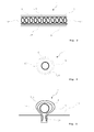
- FIG. 3 shows a schematic longitudinal section through a sealing device according to the invention 1.
- the sealing unit 5 consists of a flexible material which is in particular also high temperature resistant. In a particularly preferred embodiment, said sealing unit 5 is made of woven glass silk 10.
- a support device 6 is arranged which comprises at least one tension spring 7.
- the tension spring 7 is formed as a spiral spring 8, which preferably consists of metal and particularly preferably of spring wire 9.
- the tension spring 7 is shown schematically in this preferred embodiment as a spiral spring, but can be replaced by a tension spring 7 or in particular coil spring 8 in another embodiment.
- the diameter 17 of the sealing unit 5 located which is preferably not substantially larger than the diameter 16 of the support means. If the diameter of the supporting device 6 is too small, the permanent flattening of the sealing unit 5 could possibly no longer be prevented.
- the ratio of the diameter of the support device 6 to the diameter of the sealing unit 5 is greater than 1: 5 or 1: 4 and preferably greater than 1: 3 and particularly preferably greater than 1: 2.
- FIG. 4 shows a cross section of the sealing device 1 from FIG. 3 ,
- the sealing unit 5 consist of glass silk.
- the coil spring 8 is provided, which prevents the sealing device 1 is permanently flattened.
- FIG. 5 illustrated cross section through a further sealing device 1 shows the sealing unit 5 made of glass fiber 10 with an internal support means 6.
- the tension spring 7 is formed as a spiral spring 8.
- the sealing unit 5 is arranged in such a way to the support means 6, that a flattened part of the sealing unit 5 can be inserted into a arranged in the housing 13 groove 18.
- the support means 6 is shown in this embodiment as a circular coil spring 8. However, the support means 6 need not necessarily be in a round shape.
Landscapes
- Engineering & Computer Science (AREA)
- Chemical & Material Sciences (AREA)
- Combustion & Propulsion (AREA)
- Mechanical Engineering (AREA)
- General Engineering & Computer Science (AREA)
- Gasket Seals (AREA)
- Electric Stoves And Ranges (AREA)
- Cookers (AREA)
Abstract
Description
- Die vorliegende Erfindung betrifft eine Dichtungseinrichtung für Haushaltsgeräte wie Backöfen, kombinierte Mikrowellengeräte oder sonstige Haushaltsgeräte, die insbesondere bei sehr hohen Temperaturen verwendbar ist.
- Üblicherweise werden für Backöfen elastische Silikondichtungen zur Abdichtung des Garraumes genutzt. Diese werden in den der Tür zuweisenden Teil der Backmuffel eingehängt und sorgen dadurch für eine Abdichtung des Spaltes zwischen Backofentür und Garraum.
- Diese Art der Dichtung ist jedoch nicht geeignet für sehr hohe Temperaturen, wie sie zum Beispiel bei Öfen mit Pyrolysefunktion entstehen, da Silikondichtungen die bei der Pyrolyse entstehenden Temperaturen von z.B. 450°C nicht verkraften. Eine derart hitzebeständige Dichtung wird durch die Nutzung von Glasseide erreicht, die zu einer schlauchförmigen Dichtung gewebt wird. Um ein dauerhaftes Abplatten des Schlauches nach Schließen und Wiederöffnen der Ofentür zu verhindern, ist in den Schlauch ein stützendes Drahtgeflecht eingebracht.
- Eine bekannte thermobeständige Dichtung dieser Art ist eine schlauchförmige Dichtung aus gewebter Glasseide, wobei der Schlauch zu einer Seite hin flach abgenäht ist. Auch in dieser Variante wird das permanente Abflachen des Schlauches durch ein innenliegendes Drahtgeflecht gewährleistet. Die Montage der Dichtung erfolgt über das Einführen des abgenähten Bereiches des Dichtungsschlauches in eine in dem Gehäuse des Ofens angeordnete Nut. Dadurch wird eine zuverlässige Dichtwirkung erzielt, allerdings kann es zu produktionstechnischen Komplikationen kommen, wenn die Backmuffel zum Beispiel mit Emaille überzogen wird. Die Nut in dem Gehäuse weist zum Beispiel vor dem Emaillierungsprozess ein konstantes Spaltmaß auf. Dieses kann sich aber durch die Emaillierung teilweise verändern. Dadurch ist es möglich, dass die Dichtung zu weit in die Montagenut rutschen kann oder zu weit heraussteht, wodurch eine optimale Abdichtung zwischen Garraum und Ofentür nicht mehr gewährleistet ist.
- Eine andere bekannte Art einer solchen Dichtung ähnelt in der Aufhängung einer herkömmlichen Silikondichtung. Die Aufhängung der aus Glasseide schlauchförmig gewebten Dichtung erfolgt über Klammern, wobei die Dichtung locker vor dem Garraum hängt und durch die zuschlagende Tür in einer festen Position fixiert wird.
- Nachteilig bei dieser Art von Dichtung ist, dass das stützende Drahtgeflecht mit der Zeit ausleiern und die Dichtung somit durchhängen kann. Neben der daraus resultierenden unschönen Optik kann die Dichtung eventuell nicht mehr ideal entlang der Backofenöffnung anliegen. Auch das Abflachen der Dichtung kann durch ein Drahtgeflecht alleine gegebenenfalls nicht dauerhaft gewährleistet werden. Um die gewünschte Form des Glasseidenschlauches zu stabilisieren und das Abflachen der Dichtung zu verhindern, wird daher zusätzlich ein steifer Metallstab in den Schlauch eingeführt und in die gewünschte Form gebogen.
- Die Aufgabe der Erfindung besteht darin, eine verbesserte Dichtungseinrichtung und ein damit ausgestattetes Haushaltsgerät zur Verfügung zu stellen, die bzw. das eine optimale Dichtwirkung und einen flexiblen Einsatz bei verschiedenen Montagemöglichkeiten und Montagetoleranzen ermöglicht, während die Dichtungseinrichtung insbesondere auch für eine Pyrolysefunktion beständig ist.
- Diese Aufgabe wird erfindungsgemäß durch die Merkmale des Anspruchs 1 gelöst. Ein Haushaltsgerät mit einer erfindungsgemäßen Dichtungseinrichtung ist Gegenstand des Anspruchs 10. Vorteilhafte Ausgestaltungen und Weiterbildungen der Erfindung sind in den Unteransprüchen definiert.
- Die erfindungsgemäße Dichtungseinrichtung für Haushaltsgeräte dient insbesondere der Abdichtung von Beschickungsöffnungen von Backöfen oder ähnlichen Geräten. Die erfindungsgemäße Dichtungseinrichtung umfasst wenigstens eine schlauchförmige Dichtungseinheit, die aus einem flexiblen Material gefertigt ist. Weiterhin umfasst die Dichtungseinrichtung wenigstens eine in der Dichtungseinheit liegende Stützeinrichtung, die wenigstens eine Zugfeder umfasst. Sie ist dazu geeignet, das permanente Abflachen besagter schlauchförmigen Dichtungseinrichtung zu verhindern.
- Die erfindungsgemäße Dichtungseinrichtung hat viele Vorteile. Ein erheblicher Vorteil ist, dass das Einbringen eines stützenden Drahtgeflechts, wie es in bekannten Dichtungen benutzt wird, überflüssig werden kann, da diese Funktion durch die wenigstens eine Zugfeder umfassende Stützeinrichtung gewährleistet wird. Dadurch tritt auch das schon oben beschriebene Problem des Abflachens des Drahtgeflechts über die Zeit nicht auf. Besonders bevorzugt ist die Stützeinrichtung dazu bestimmt, die grundsätzliche Form der Dichtungseinrichtung vorzugeben. Im Gegensatz zu dem stützenden Drahtgeflecht kann die vorliegende Stützeinrichtung nicht nur das Abflachen der schlauchförmigen Dichtungseinheit verhindern, sondern auch z.B. die die Backofenöffnung umlaufende Form vorgeben und dauerhaft gehalten werden.
- Hierdurch wird das zusätzliche Einführen eines starren Stützdrahtes in die Dichtungseinheit, wie es bei bekannten Dichtungen der Fall ist, überflüssig, da auch diese formgebende Funktion durch die wenigstens eine Zugfeder umfassende Stützeinrichtung übernommen wird. Weiterhin entsteht hierdurch auch eine flexiblere Einsatzmöglichkeit der Dichtungseinrichtung, da diese durch die besagte Zugfeder unter Spannung unterschiedliche Formen einnehmen kann.
- Die Stützeinrichtung der erfindungsgemäßen Dichtungseinrichtung umfasst vorzugsweise eine Spiralfeder, wobei die Stützeinrichtung bevorzugt aus Metall und besonders bevorzugt aus Federstahldraht besteht.
- Da die erfindungsgemäße Dichtungseinrichtung besonders für hohe Temperaturen, wie sie zum Beispiel bei der Reinigung von Backöfen im Pyrolysebetrieb entstehen, geeignet ist, besteht die Dichtungseinheit vorzugsweise aus einem hochtemperaturbeständigen Material, besonders bevorzugt allerdings aus Glasseide.
- Wenigstens eine Dichtungseinheit kann durchgängig und die Backofenmuffelöffnung umschlie-βend ausgebildet sein.
- Bevorzugter Weise kann die Dichtungseinrichtung aber auch zwei oder mehr Dichtungseinheiten umfassen. Jede Dichtungseinheit kann mit jeweils zwei offenen Enden ausprägt sein, wobei sich die Enden von wenigstens einer solchen Dichtungseinheit insbesondere gegenüberliegen, bevorzugt aber auch zum Beispiel in den Ecken aneinander stoßen oder besonders bevorzugt sich sogar überlappen.
- Möglich ist es auch, dass die Stützeinrichtung vorgespannt ist. Dies könnte über das Spannen wenigstens einer Stützeinrichtung auf einen geeigneten Montagerahmen erfolgen. Denkbar ist aber auch, dass als Stützeinrichtung eine geschlossene Spiralfeder vorgesehen ist, die im Umfang kleiner als der die Backmuffelöffnung zu umgebende Bereich ist. Dadurch wäre eine Montage an zum Beispiel vier dafür vorgesehen Montagezapfen möglich, indem man die dann gespannte Spiralfeder über die Zapfen legt.
- Vorzugsweise wird die erfindungsgemäße Dichtungseinrichtung an einem Haushaltsgerät mit wenigstens einer Befestigungseinheit angebracht. Dies kann insbesondere über zum Beispiel vier Klammern erfolgen, die jeweils an den Ecken der Backmuffelöffnung an dem Gehäuse befestigt werden. Es ist aber auch möglich die Dichtungseinrichtung um dafür vorgesehene Monatgestellen zu spannen und anschließend die Enden wenigstens einer Dichtungseinheit zu verbinden.
- Auch wenn die erfindungsgemäße Dichtungseinrichtung auf ein innenliegendes Stützgeflecht verzichten kann, ist es möglich, in einer weiteren Ausführung zusätzlich wie in herkömmlichen Dichtungen ein stützendes Drahtgeflecht in die Dichtungseinheit einzubringen.
- Ein erfindungsgemäßes Haushaltsgerät ist besonders bevorzugt als Backofen ausgeführt. Das Haushaltsgerät weist wenigstens ein Gehäuse mit wenigstens einer Backmuffel auf. Weiterhin ist eine die Backmuffelöffnung verschließende Tür vorgesehen. Zwischen dem Gehäuse und der Tür ist wenigstens eine Dichtungseinrichtung vorgesehen. Die Dichtungseinrichtung umfasst wenigstens eine Dichtungseinheit, welche aus einem flexiblen Material besteht. Die Dichtungseinrichtung umfasst weiterhin wenigstens eine Stützeinrichtung, die wenigstens eine Zugfeder aufweist. Die Stützeinrichtung ist dazu geeignet, das permanente Abflachen besagter schlauchförmigen Dichtungseinrichtung zu verhindern. Vorzugsweise ist die Stützeinrichtung dazu bestimmt, die grundsätzliche Form der Dichtungseinrichtung vorzugeben.
- Vorzugsweise ist es bei einem solchen Haushaltsgerät mit einer wie oben beschriebenen Dichtungseinrichtung möglich, dass besagte Dichtungseinrichtung in einer die Backofenmuffel umschließenden Nut angeordnet ist. Hierdurch ist es möglich, dass weitere Befestigungseinrichtungen überflüssig werden.
- Eine weitere Ausgestaltung eines solchen Haushaltsgerätes ist denkbar, in der die erfindungsgemäße Dichtungseinrichtung in wenigstens einer Befestigungseinheit, zum Beispiel in einem Rahmen, vorgespannt gehalten wird. Diese Befestigungseinheit wird dann an dem Gehäuse des Haushaltsgerätes an vorgesehen Befestigungsstellen angeordnet.
- Weitere Vorteile und Eigenschaften der vorliegenden Erfindung ergeben sich aus den Ausführungsbeispielen, die mit Bezug auf die beiliegenden Figuren im Folgenden beschrieben werden.
- Darin zeigen:
- Fig. 1
- eine leicht perspektivische Gesamtansicht eines Haushaltgerätes 2, insbesondere eines Backofens 3;
- Fig. 2
- eine Teilansicht auf eine geöffnete Backmuffelöffnung 4 mit einer montierten erfindungsgemäßen Dichtungseinrichtung 1;
- Fig. 3
- einen Längsschnitt durch eine erfindungsgemäße Dichtungseinrichtung 1;
- Fig. 4
- einen Querschnitt durch die Dichtungseinrichtung 1 nach
Fig.3 ; und - Fig. 5
- einen Querschnitt durch eine weitere erfindungsgemäße Dichtungseinrichtung 1.
-
Figur 1 zeigt eine leicht perspektivische Gesamtansicht eines Haushaltsgerätes 2, in diesem speziellen Fall handelt es sich um einen Backofen 3. Der Backofen 3 mit dem Gehäuse 13 hat oben angeordnet vier Kochfelder 19, die als Strahlungs- oder Induktionskochfelder ausgeprägt sein können. Des Weiteren ist ein Steuerelement 20 mit drehbaren Reglern 21 vorhanden. Es kann in diesem Bereich auch ein Display vorgesehen sein. - Die erfindungsgemäße Dichtungseinrichtung 1 befindet sich in
Figur 1 nicht sichtbar hinter der Tür 15 des Backofens 3. Durch das Fenster der Tür 15 kann man in die Backmuffel 4 gucken. -
Figur 2 zeigt eine Teilansicht des Haushaltgerätes 2. Es ist eine Ansicht auf die offen stehende Beschickungsöffnung 4 des Backofens 3, die in das Gehäuse 13 des Backofens 3 eingelassen ist. Die Tür 15 ist in dieser Figur nicht eingezeichnet. - Die Backofenmuffel 4 ist von einer erfindungsgemäßen Dichtungseinrichtung 1 umgeben. In dem hier dargestellten Fall ist eine Dichtungseinheit 5 zu einer durchgängigen Dichtungseinrichtung 1 verbunden. Die Dichtungseinrichtung 1 ist im vorliegenden Beispiel über vier Befestigungseinheiten 12 mit dem Gehäuse verbunden.
- Durch die Spannung der Stützeinrichtung 6 (vergleiche
Figur 3 ) um die Befestigungseinheiten 12 gibt die besagte Stützeinrichtung 6 die gewünschte Form der Dichtungseinrichtung 1 vor. Die Dichtungseinrichtung 1 liegt bevorzugt stramm am Gehäuse 13 an und hängt zwischen den Befestigungseinheiten 12 nicht oder nur unwesentlich durch. - In einer weiteren nicht dargestellten bevorzugten Ausführungsform kann die Dichtungseinrichtung 1 eine nicht- durchgängige Dichtungseinheit 5 umfassen. In diesem Fall können sich die beiden Enden einer Dichtungseinheit 5 vorzugsweise abschließend gegenüberliegen, in einer Ecke gegeneinander stoßen oder sich sogar überlappen.
- In
Figur 2 ist eine weitere bevorzugte Ausführungsform gestrichelt angedeutet. Hierbei besteht die Dichtungseinrichtung 1 nicht nur aus einer Dichtungseinheit 5, sondern kann aus mehreren Dichtungseinheiten 5 bestehen, die an ihren Enden 11a, 11 b zum Beispiel jeweils über die Befestigungseinheiten 12 mit dem Gehäuse 13 verbunden sind. Davon ist beispielhaft eine Dichtungseinheit 5 gestrichelt eingezeichnet. - Weiterhin kann die Dichtungseinheit 1 auch vorgespannt auf einer Befestigungseinheit, insbesondere auf einer rahmenähnlichen Konstruktion, vorgespannt angeordnet sein. In diesem nicht dargestellten bevorzugten Ausführungsbeispiel wird die Dichtungseinrichtung 1 mittels des Rahmens an dem Gehäuse 13 befestigt.
-
Figur 3 zeigt einen schematischen Längsschnitt durch eine erfindungsgemäße Dichtungseinrichtung 1. Die Dichtungseinheit 5 besteht aus einem flexiblen Material, welches insbesondere auch hochtemperaturbeständig ist. In einer besonders bevorzugten Ausführung besteht besagte Dichtungseinheit 5 aus gewebter Glasseide 10. Im Inneren der Dichtungseinheit 5 ist eine Stützeinrichtung 6 angeordnet, die wenigstens eine Zugfeder 7 umfasst. Im dargestellten Ausführungsbeispiel ist die Zugfeder 7 als Spiralfeder 8 ausgebildet, die vorzugsweise aus Metall und besonders bevorzugt aus Federdraht 9 besteht. - Die Zugfeder 7 ist in diesem bevorzugten Ausführungsbeispiel schematisch als Spiralfeder dargestellt, kann aber durch eine Zugfeder 7 oder insbesondere Spiralfeder 8 in einer anderen Ausgestaltung ausgetauscht werden.
- Es ist der Durchmesser 17 der Dichtungseinheit 5 eingezeichnet der bevorzugt nicht wesentlich größer als der Durchmesser 16 der Stützeinrichtung ist. Bei einem zu geringen Durchmesser der Stützeinrichtung 6 könnte das permanente Abflachen der Dichtungseinheit 5 eventuell nicht mehr verhindert werden. Insbesondere ist das Verhältnis des Durchmessers der Stützeinrichtung 6 zu dem Durchmesser der Dichtungseinheit 5 größer als 1:5 bzw. 1:4 und vorzugsweise größer als 1:3 und besonders bevorzugt größer als 1:2.
-
Figur 4 zeigt einen Querschnitt der Dichtungseinrichtung 1 ausFigur 3 . Die Dichtungseinheit 5 bestehe aus Glasseide. Konzentrisch ist die Spiralfeder 8 vorgesehen, die verhindert, dass die Dichtungseinrichtung 1 dauerhaft abgeflacht wird. - Der in
Figur 5 dargestellte Querschnitt durch eine weitere erfindungsgemäße Dichtungseinrichtung 1 zeigt die Dichtungseinheit 5 aus Glasseide 10 mit einer innenliegenden Stützeinrichtung 6. Auch in diesem bevorzugten Ausführungsbeispiel ist die Zugfeder 7 als Spiralfeder 8 ausgebildet. Jedoch erfolgt hier die Montage nicht wie inFigur 1 dargestellt mittels der Befestigungseinheiten 12. Die Dichtungseinheit 5 wird auf eine solche Art um die Stützeinrichtung 6 angeordnet, dass ein abgeflachter Teil der Dichtungseinheit 5 in eine in dem Gehäuse 13 angeordnete Nut 18 eingeschoben werden kann. Die Stützeinrichtung 6 ist in diesem Ausführungsbeispiel als eine kreisrunde Spiralfeder 8 dargestellt. Die Stützeinrichtung 6 muss jedoch nicht unbedingt in einer runden Form vorliegen. -
- 1
- Dichtungseinrichtung
- 2
- Haushaltsgerät
- 3
- Backofen
- 4
- Beschickungs-/ Backmuffelöffnung
- 5
- Dichtungseinheit
- 6
- Stützeinrichtung
- 7
- Zugfeder
- 8
- Spiralfeder
- 9
- Federstahldraht
- 10
- Glasseide
- 11 a/b
- 1./2. Ende einer Dichtungseinheit
- 12
- Befestigungseinheit
- 13
- Gehäuse
- 14
- Backofenmuffel
- 15
- Tür
- 16
- Durchmesser der Dichtungseinheit
- 17
- Durchmesser der Stützeinrichtung
- 18
- Nut
- 19
- Kochfelder
- 20
- Steuerelement
- 21
- Regler
Claims (11)
- Dichtungseinrichtung (1) für Haushaltsgeräte (2), insbesondere zum Abdichten einer Beschickungsöffnung (4) von Backöfen (3) oder ähnlichen Geräten, umfassend wenigstens eine schlauchförmige Dichtungseinheit (5) mit wenigstens einer innenliegenden Stützeinrichtung (6),
wobei die schlauchförmige Dichtungseinheit (5) aus einem flexiblen Material besteht, dadurch gekennzeichnet,
dass die Stützeinrichtung (6) wenigstens eine Zugfeder (7) umfasst, die dazu geeignet ist, das permanente Abflachen der Dichtungseinheit (5) zu verhindern. - Dichtungseinrichtung (1) nach Anspruch 1,
dadurch gekennzeichnet,
dass die Stützeinrichtung (6) dazu bestimmt ist, die grundsätzliche Form der Dichtungseinrichtung (1) vorzugeben. - Dichtungseinrichtung (1) nach einem der vorhergehenden Ansprüche,
dadurch gekennzeichnet,
dass wenigstens eine Zugfeder (7) als Spiralfeder (8) ausgebildet ist, welche insbesondere aus einem Metall und vorzugsweise aus Federstahldraht (9) besteht. - Dichtungseinrichtung (1) nach einem der vorhergehenden Ansprüche,
dadurch gekennzeichnet,
dass das Material der schlauchförmigen Dichtungseinheit (5) hochtemperaturbeständig ist und insbesondere wenigstens teilweise aus Glasseide (10) besteht. - Dichtungseinrichtung (1) nach einem der vorhergehenden Ansprüche,
dadurch gekennzeichnet,
dass die Enden der Dichtungseinheit (5) miteinander zu einem durchgängigen Element verbunden sind. - Dichtungseinrichtung (1) nach einem der vorhergehenden Ansprüche,
dadurch gekennzeichnet,
dass sich die Enden (11a, 11 b) wenigstens einer Dichtungseinheit (5) gegenüberliegen, aneinander stoßen oder sogar überlappen. - Dichtungseinrichtung (1) nach einem der vorhergehenden Ansprüche,
dadurch gekennzeichnet,
dass wenigstens eine Befestigungseinheit (12) zur Montage wenigstens einer Dichtungseinrichtung (1) vorgesehen ist, um diese wenigstens teilweise an einem Haushaltsgerät zu fixieren. - Dichtungseinrichtung (1) nach einem der vorhergehenden Ansprüche,
dadurch gekennzeichnet,
dass die schlauchförmige Dichtungseinheit (5) zusätzlich im Wesentlichen von einem stützenden Geflecht, insbesondere einem Drahtgeflecht, ausgekleidet ist. - Haushaltsgerät (2), insbesondere ein Backofen (3), mit einem Gehäuse (13) und wenigstens einer Backmuffel (14) und einer die Backmuffelöffnung (4) verschließenden Tür (15),
dadurch gekennzeichnet,
dass zwischen dem Gehäuse und der Tür wenigstens eine Dichtungseinrichtung (1) nach einem der vorhergehenden Ansprüche vorgesehen ist. - Haushaltsgerät (2) nach Anspruch 9,
dadurch gekennzeichnet,
dass wenigstens eine Dichtungseinrichtung (1) in einer die Backofenmuffel (14) umschließenden Nut (18) angeordnet ist. - Haushaltsgerät (2) nach Anspruch 9 oder 10,
dadurch gekennzeichnet,
dass die Dichtungseinrichtung (1) in wenigstens einer Befestigungseinheit vorgespannt gehalten wird und in an dem Gehäuse vorgesehen Befestigungsstellen angeordnet wird.
Applications Claiming Priority (1)
| Application Number | Priority Date | Filing Date | Title |
|---|---|---|---|
| DE200910059205 DE102009059205A1 (de) | 2009-12-18 | 2009-12-18 | Dichtungseinrichtung für ein Haushaltsgerät |
Publications (2)
| Publication Number | Publication Date |
|---|---|
| EP2336645A1 true EP2336645A1 (de) | 2011-06-22 |
| EP2336645B1 EP2336645B1 (de) | 2017-06-28 |
Family
ID=43770500
Family Applications (1)
| Application Number | Title | Priority Date | Filing Date |
|---|---|---|---|
| EP10401205.9A Not-in-force EP2336645B1 (de) | 2009-12-18 | 2010-12-01 | Haushaltsgerät mit einer Dichtungseinrichtung |
Country Status (2)
| Country | Link |
|---|---|
| EP (1) | EP2336645B1 (de) |
| DE (1) | DE102009059205A1 (de) |
Cited By (1)
| Publication number | Priority date | Publication date | Assignee | Title |
|---|---|---|---|---|
| CN108756685A (zh) * | 2018-07-25 | 2018-11-06 | 宁波市菲德克密封科技有限公司 | 密封垫 |
Families Citing this family (1)
| Publication number | Priority date | Publication date | Assignee | Title |
|---|---|---|---|---|
| DE102020213921B3 (de) | 2020-11-05 | 2022-02-03 | Biw Isolierstoffe Gmbh | Dichtungselement, insbesondere zur Abdichtung einer Backofen- oder Kamintüre |
Citations (2)
| Publication number | Priority date | Publication date | Assignee | Title |
|---|---|---|---|---|
| DE20314238U1 (de) * | 2002-10-01 | 2004-03-04 | Davlyn Manufacturing Co. Inc., Spring | Clip-Dichtungsabschluss |
| FR2931919A1 (fr) * | 2008-06-02 | 2009-12-04 | Fed Mogul Systems Prot Group | Joint d'etancheite, piece de four equipe d'un tel joint et four comprenant un tel joint |
Family Cites Families (4)
| Publication number | Priority date | Publication date | Assignee | Title |
|---|---|---|---|---|
| DE462051C (de) * | 1928-07-04 | Paul Hoffmann | Koksofentuerdichtung | |
| GB718345A (en) * | 1952-11-01 | 1954-11-10 | Parkinson Stove Co Ltd | New or improved sealing means for the doors of cooker ovens and the like |
| US5205075A (en) * | 1991-03-06 | 1993-04-27 | The Bentley-Harris Manufacturing Company | Gaskets for sealing a space between surfaces and clips for mounting gaskets to surfaces |
| US6039325A (en) * | 1996-10-17 | 2000-03-21 | The United States Of America As Represented By The Administrator Of National Aeronautics And Space Administration | Resilient braided rope seal |
-
2009
- 2009-12-18 DE DE200910059205 patent/DE102009059205A1/de not_active Withdrawn
-
2010
- 2010-12-01 EP EP10401205.9A patent/EP2336645B1/de not_active Not-in-force
Patent Citations (2)
| Publication number | Priority date | Publication date | Assignee | Title |
|---|---|---|---|---|
| DE20314238U1 (de) * | 2002-10-01 | 2004-03-04 | Davlyn Manufacturing Co. Inc., Spring | Clip-Dichtungsabschluss |
| FR2931919A1 (fr) * | 2008-06-02 | 2009-12-04 | Fed Mogul Systems Prot Group | Joint d'etancheite, piece de four equipe d'un tel joint et four comprenant un tel joint |
Cited By (1)
| Publication number | Priority date | Publication date | Assignee | Title |
|---|---|---|---|---|
| CN108756685A (zh) * | 2018-07-25 | 2018-11-06 | 宁波市菲德克密封科技有限公司 | 密封垫 |
Also Published As
| Publication number | Publication date |
|---|---|
| DE102009059205A1 (de) | 2011-06-22 |
| EP2336645B1 (de) | 2017-06-28 |
Similar Documents
| Publication | Publication Date | Title |
|---|---|---|
| EP2469177A1 (de) | Gargerät | |
| EP2336645B1 (de) | Haushaltsgerät mit einer Dichtungseinrichtung | |
| EP1360440A2 (de) | Gargerät mit tür | |
| DE3047380C2 (de) | ||
| DE102014203532A1 (de) | Mikrowellengargerät mit einer speziellen Mikrowellenfalle | |
| DE3419452A1 (de) | Verschluss-dichtung | |
| DE102008033535A1 (de) | Hausgerät | |
| DE10149085B4 (de) | Backofentür | |
| EP1448933A1 (de) | Türdichtungsstrang und gargerät | |
| DE19649047C2 (de) | Haushaltsgerät mit einer Bedienblende, die mit von vorne nicht sichtbaren Befestigungselementen befestigt ist | |
| DE10350197A1 (de) | Verbindung und Befestigung von Dichtungen für Anwendung bei hohen Temperaturen für Backofentüren | |
| WO2015110382A1 (de) | Gargerät | |
| DE102010050725B4 (de) | Dichtung für ein Gargerät | |
| DE10328885B4 (de) | Wärmegerät, insbesondrere Backofen | |
| DE102013206041B4 (de) | Befestigung einer Backofendichtung | |
| EP3407679A1 (de) | Verfahren und vorrichtung zur leckstrahlsicheren abdichtung eines heizkörpers mit einem bodenblech für einen kombinierten dampfgarer mit mikrowellenfunktion | |
| DE102013106590B4 (de) | Befestigungseinrichtung und Gargerät mit einer Befestigungseinrichtung | |
| DE102015218880B4 (de) | Befestigung einer Backofendichtung | |
| DE2929332C2 (de) | Einbau-Kochfeld mit einer großflächigen Kochplatte aus glaskeramischem Material | |
| DE102005023912A1 (de) | Backofentür | |
| CH651354A5 (en) | Door arrangement for an electromagnetically shielded room | |
| DE102012203380A1 (de) | Kochfeld mit einem Montagerahmen in einem Zierrahmen sowie Verfahren zum Herstellen eines Kochfelds | |
| DE102016114816B4 (de) | Gargerät | |
| DE202024105422U1 (de) | Gargerät mit dichtender Abstandshülse | |
| DE102006039498A1 (de) | Durchlauferhitzer zur Schnellmontage |
Legal Events
| Date | Code | Title | Description |
|---|---|---|---|
| PUAI | Public reference made under article 153(3) epc to a published international application that has entered the european phase |
Free format text: ORIGINAL CODE: 0009012 |
|
| AK | Designated contracting states |
Kind code of ref document: A1 Designated state(s): AL AT BE BG CH CY CZ DE DK EE ES FI FR GB GR HR HU IE IS IT LI LT LU LV MC MK MT NL NO PL PT RO RS SE SI SK SM TR |
|
| 17P | Request for examination filed |
Effective date: 20111210 |
|
| 17Q | First examination report despatched |
Effective date: 20160531 |
|
| GRAP | Despatch of communication of intention to grant a patent |
Free format text: ORIGINAL CODE: EPIDOSNIGR1 |
|
| INTG | Intention to grant announced |
Effective date: 20170208 |
|
| GRAS | Grant fee paid |
Free format text: ORIGINAL CODE: EPIDOSNIGR3 |
|
| GRAA | (expected) grant |
Free format text: ORIGINAL CODE: 0009210 |
|
| AK | Designated contracting states |
Kind code of ref document: B1 Designated state(s): AL AT BE BG CH CY CZ DE DK EE ES FI FR GB GR HR HU IE IS IT LI LT LU LV MC MK MT NL NO PL PT RO RS SE SI SK SM TR |
|
| REG | Reference to a national code |
Ref country code: GB Ref legal event code: FG4D Free format text: NOT ENGLISH |
|
| REG | Reference to a national code |
Ref country code: CH Ref legal event code: EP |
|
| REG | Reference to a national code |
Ref country code: DE Ref legal event code: R084 Ref document number: 502010013802 Country of ref document: DE |
|
| REG | Reference to a national code |
Ref country code: AT Ref legal event code: REF Ref document number: 905217 Country of ref document: AT Kind code of ref document: T Effective date: 20170715 |
|
| REG | Reference to a national code |
Ref country code: IE Ref legal event code: FG4D Free format text: LANGUAGE OF EP DOCUMENT: GERMAN |
|
| REG | Reference to a national code |
Ref country code: DE Ref legal event code: R096 Ref document number: 502010013802 Country of ref document: DE |
|
| REG | Reference to a national code |
Ref country code: GB Ref legal event code: 746 Effective date: 20170721 |
|
| PG25 | Lapsed in a contracting state [announced via postgrant information from national office to epo] |
Ref country code: NO Free format text: LAPSE BECAUSE OF FAILURE TO SUBMIT A TRANSLATION OF THE DESCRIPTION OR TO PAY THE FEE WITHIN THE PRESCRIBED TIME-LIMIT Effective date: 20170928 Ref country code: HR Free format text: LAPSE BECAUSE OF FAILURE TO SUBMIT A TRANSLATION OF THE DESCRIPTION OR TO PAY THE FEE WITHIN THE PRESCRIBED TIME-LIMIT Effective date: 20170628 Ref country code: GR Free format text: LAPSE BECAUSE OF FAILURE TO SUBMIT A TRANSLATION OF THE DESCRIPTION OR TO PAY THE FEE WITHIN THE PRESCRIBED TIME-LIMIT Effective date: 20170929 Ref country code: LT Free format text: LAPSE BECAUSE OF FAILURE TO SUBMIT A TRANSLATION OF THE DESCRIPTION OR TO PAY THE FEE WITHIN THE PRESCRIBED TIME-LIMIT Effective date: 20170628 Ref country code: FI Free format text: LAPSE BECAUSE OF FAILURE TO SUBMIT A TRANSLATION OF THE DESCRIPTION OR TO PAY THE FEE WITHIN THE PRESCRIBED TIME-LIMIT Effective date: 20170628 |
|
| REG | Reference to a national code |
Ref country code: NL Ref legal event code: MP Effective date: 20170628 |
|
| REG | Reference to a national code |
Ref country code: LT Ref legal event code: MG4D |
|
| PG25 | Lapsed in a contracting state [announced via postgrant information from national office to epo] |
Ref country code: LV Free format text: LAPSE BECAUSE OF FAILURE TO SUBMIT A TRANSLATION OF THE DESCRIPTION OR TO PAY THE FEE WITHIN THE PRESCRIBED TIME-LIMIT Effective date: 20170628 Ref country code: BG Free format text: LAPSE BECAUSE OF FAILURE TO SUBMIT A TRANSLATION OF THE DESCRIPTION OR TO PAY THE FEE WITHIN THE PRESCRIBED TIME-LIMIT Effective date: 20170928 Ref country code: RS Free format text: LAPSE BECAUSE OF FAILURE TO SUBMIT A TRANSLATION OF THE DESCRIPTION OR TO PAY THE FEE WITHIN THE PRESCRIBED TIME-LIMIT Effective date: 20170628 Ref country code: SE Free format text: LAPSE BECAUSE OF FAILURE TO SUBMIT A TRANSLATION OF THE DESCRIPTION OR TO PAY THE FEE WITHIN THE PRESCRIBED TIME-LIMIT Effective date: 20170628 Ref country code: NL Free format text: LAPSE BECAUSE OF FAILURE TO SUBMIT A TRANSLATION OF THE DESCRIPTION OR TO PAY THE FEE WITHIN THE PRESCRIBED TIME-LIMIT Effective date: 20170628 |
|
| REG | Reference to a national code |
Ref country code: FR Ref legal event code: PLFP Year of fee payment: 8 |
|
| PG25 | Lapsed in a contracting state [announced via postgrant information from national office to epo] |
Ref country code: EE Free format text: LAPSE BECAUSE OF FAILURE TO SUBMIT A TRANSLATION OF THE DESCRIPTION OR TO PAY THE FEE WITHIN THE PRESCRIBED TIME-LIMIT Effective date: 20170628 Ref country code: RO Free format text: LAPSE BECAUSE OF FAILURE TO SUBMIT A TRANSLATION OF THE DESCRIPTION OR TO PAY THE FEE WITHIN THE PRESCRIBED TIME-LIMIT Effective date: 20170628 Ref country code: CZ Free format text: LAPSE BECAUSE OF FAILURE TO SUBMIT A TRANSLATION OF THE DESCRIPTION OR TO PAY THE FEE WITHIN THE PRESCRIBED TIME-LIMIT Effective date: 20170628 Ref country code: SK Free format text: LAPSE BECAUSE OF FAILURE TO SUBMIT A TRANSLATION OF THE DESCRIPTION OR TO PAY THE FEE WITHIN THE PRESCRIBED TIME-LIMIT Effective date: 20170628 |
|
| PG25 | Lapsed in a contracting state [announced via postgrant information from national office to epo] |
Ref country code: IS Free format text: LAPSE BECAUSE OF FAILURE TO SUBMIT A TRANSLATION OF THE DESCRIPTION OR TO PAY THE FEE WITHIN THE PRESCRIBED TIME-LIMIT Effective date: 20171028 Ref country code: PL Free format text: LAPSE BECAUSE OF FAILURE TO SUBMIT A TRANSLATION OF THE DESCRIPTION OR TO PAY THE FEE WITHIN THE PRESCRIBED TIME-LIMIT Effective date: 20170628 Ref country code: SM Free format text: LAPSE BECAUSE OF FAILURE TO SUBMIT A TRANSLATION OF THE DESCRIPTION OR TO PAY THE FEE WITHIN THE PRESCRIBED TIME-LIMIT Effective date: 20170628 Ref country code: ES Free format text: LAPSE BECAUSE OF FAILURE TO SUBMIT A TRANSLATION OF THE DESCRIPTION OR TO PAY THE FEE WITHIN THE PRESCRIBED TIME-LIMIT Effective date: 20170628 |
|
| REG | Reference to a national code |
Ref country code: DE Ref legal event code: R097 Ref document number: 502010013802 Country of ref document: DE |
|
| PG25 | Lapsed in a contracting state [announced via postgrant information from national office to epo] |
Ref country code: DK Free format text: LAPSE BECAUSE OF FAILURE TO SUBMIT A TRANSLATION OF THE DESCRIPTION OR TO PAY THE FEE WITHIN THE PRESCRIBED TIME-LIMIT Effective date: 20170628 |
|
| PLBE | No opposition filed within time limit |
Free format text: ORIGINAL CODE: 0009261 |
|
| STAA | Information on the status of an ep patent application or granted ep patent |
Free format text: STATUS: NO OPPOSITION FILED WITHIN TIME LIMIT |
|
| 26N | No opposition filed |
Effective date: 20180329 |
|
| REG | Reference to a national code |
Ref country code: CH Ref legal event code: PL |
|
| PG25 | Lapsed in a contracting state [announced via postgrant information from national office to epo] |
Ref country code: SI Free format text: LAPSE BECAUSE OF FAILURE TO SUBMIT A TRANSLATION OF THE DESCRIPTION OR TO PAY THE FEE WITHIN THE PRESCRIBED TIME-LIMIT Effective date: 20170628 |
|
| REG | Reference to a national code |
Ref country code: IE Ref legal event code: MM4A |
|
| PG25 | Lapsed in a contracting state [announced via postgrant information from national office to epo] |
Ref country code: MT Free format text: LAPSE BECAUSE OF FAILURE TO SUBMIT A TRANSLATION OF THE DESCRIPTION OR TO PAY THE FEE WITHIN THE PRESCRIBED TIME-LIMIT Effective date: 20170628 Ref country code: LU Free format text: LAPSE BECAUSE OF NON-PAYMENT OF DUE FEES Effective date: 20171201 |
|
| REG | Reference to a national code |
Ref country code: BE Ref legal event code: MM Effective date: 20171231 |
|
| PG25 | Lapsed in a contracting state [announced via postgrant information from national office to epo] |
Ref country code: IE Free format text: LAPSE BECAUSE OF NON-PAYMENT OF DUE FEES Effective date: 20171201 |
|
| PG25 | Lapsed in a contracting state [announced via postgrant information from national office to epo] |
Ref country code: CH Free format text: LAPSE BECAUSE OF NON-PAYMENT OF DUE FEES Effective date: 20171231 Ref country code: LI Free format text: LAPSE BECAUSE OF NON-PAYMENT OF DUE FEES Effective date: 20171231 Ref country code: BE Free format text: LAPSE BECAUSE OF NON-PAYMENT OF DUE FEES Effective date: 20171231 |
|
| REG | Reference to a national code |
Ref country code: AT Ref legal event code: MM01 Ref document number: 905217 Country of ref document: AT Kind code of ref document: T Effective date: 20171201 |
|
| PG25 | Lapsed in a contracting state [announced via postgrant information from national office to epo] |
Ref country code: AT Free format text: LAPSE BECAUSE OF NON-PAYMENT OF DUE FEES Effective date: 20171201 |
|
| PG25 | Lapsed in a contracting state [announced via postgrant information from national office to epo] |
Ref country code: MC Free format text: LAPSE BECAUSE OF FAILURE TO SUBMIT A TRANSLATION OF THE DESCRIPTION OR TO PAY THE FEE WITHIN THE PRESCRIBED TIME-LIMIT Effective date: 20170628 Ref country code: HU Free format text: LAPSE BECAUSE OF FAILURE TO SUBMIT A TRANSLATION OF THE DESCRIPTION OR TO PAY THE FEE WITHIN THE PRESCRIBED TIME-LIMIT; INVALID AB INITIO Effective date: 20101201 |
|
| PG25 | Lapsed in a contracting state [announced via postgrant information from national office to epo] |
Ref country code: CY Free format text: LAPSE BECAUSE OF NON-PAYMENT OF DUE FEES Effective date: 20170628 |
|
| PG25 | Lapsed in a contracting state [announced via postgrant information from national office to epo] |
Ref country code: MK Free format text: LAPSE BECAUSE OF FAILURE TO SUBMIT A TRANSLATION OF THE DESCRIPTION OR TO PAY THE FEE WITHIN THE PRESCRIBED TIME-LIMIT Effective date: 20170628 |
|
| PG25 | Lapsed in a contracting state [announced via postgrant information from national office to epo] |
Ref country code: TR Free format text: LAPSE BECAUSE OF FAILURE TO SUBMIT A TRANSLATION OF THE DESCRIPTION OR TO PAY THE FEE WITHIN THE PRESCRIBED TIME-LIMIT Effective date: 20170628 |
|
| PG25 | Lapsed in a contracting state [announced via postgrant information from national office to epo] |
Ref country code: PT Free format text: LAPSE BECAUSE OF FAILURE TO SUBMIT A TRANSLATION OF THE DESCRIPTION OR TO PAY THE FEE WITHIN THE PRESCRIBED TIME-LIMIT Effective date: 20170628 |
|
| PG25 | Lapsed in a contracting state [announced via postgrant information from national office to epo] |
Ref country code: AL Free format text: LAPSE BECAUSE OF FAILURE TO SUBMIT A TRANSLATION OF THE DESCRIPTION OR TO PAY THE FEE WITHIN THE PRESCRIBED TIME-LIMIT Effective date: 20170628 |
|
| PGFP | Annual fee paid to national office [announced via postgrant information from national office to epo] |
Ref country code: FR Payment date: 20201229 Year of fee payment: 11 Ref country code: GB Payment date: 20201228 Year of fee payment: 11 |
|
| PGFP | Annual fee paid to national office [announced via postgrant information from national office to epo] |
Ref country code: IT Payment date: 20201221 Year of fee payment: 11 |
|
| PGFP | Annual fee paid to national office [announced via postgrant information from national office to epo] |
Ref country code: DE Payment date: 20201231 Year of fee payment: 11 |
|
| REG | Reference to a national code |
Ref country code: DE Ref legal event code: R119 Ref document number: 502010013802 Country of ref document: DE |
|
| GBPC | Gb: european patent ceased through non-payment of renewal fee |
Effective date: 20211201 |
|
| PG25 | Lapsed in a contracting state [announced via postgrant information from national office to epo] |
Ref country code: GB Free format text: LAPSE BECAUSE OF NON-PAYMENT OF DUE FEES Effective date: 20211201 Ref country code: DE Free format text: LAPSE BECAUSE OF NON-PAYMENT OF DUE FEES Effective date: 20220701 |
|
| PG25 | Lapsed in a contracting state [announced via postgrant information from national office to epo] |
Ref country code: FR Free format text: LAPSE BECAUSE OF NON-PAYMENT OF DUE FEES Effective date: 20211231 |
|
| PG25 | Lapsed in a contracting state [announced via postgrant information from national office to epo] |
Ref country code: IT Free format text: LAPSE BECAUSE OF NON-PAYMENT OF DUE FEES Effective date: 20211201 |