EP2330480A1 - Anpassung tragbarer elektrischer Vorrichtungen zum drahtlosen Leistungsempfang - Google Patents
Anpassung tragbarer elektrischer Vorrichtungen zum drahtlosen Leistungsempfang Download PDFInfo
- Publication number
- EP2330480A1 EP2330480A1 EP11152593A EP11152593A EP2330480A1 EP 2330480 A1 EP2330480 A1 EP 2330480A1 EP 11152593 A EP11152593 A EP 11152593A EP 11152593 A EP11152593 A EP 11152593A EP 2330480 A1 EP2330480 A1 EP 2330480A1
- Authority
- EP
- European Patent Office
- Prior art keywords
- power
- receiving element
- portable electrical
- electrical device
- connectors
- Prior art date
- Legal status (The legal status is an assumption and is not a legal conclusion. Google has not performed a legal analysis and makes no representation as to the accuracy of the status listed.)
- Withdrawn
Links
- 239000000853 adhesive Substances 0.000 claims abstract description 17
- 230000001070 adhesive effect Effects 0.000 claims abstract description 17
- 230000001939 inductive effect Effects 0.000 claims description 20
- 238000000034 method Methods 0.000 claims description 12
- 230000005674 electromagnetic induction Effects 0.000 claims description 4
- 238000009420 retrofitting Methods 0.000 claims description 2
- 238000013461 design Methods 0.000 description 5
- 238000010295 mobile communication Methods 0.000 description 5
- 239000003990 capacitor Substances 0.000 description 3
- 230000003750 conditioning effect Effects 0.000 description 3
- 239000011162 core material Substances 0.000 description 3
- 230000001965 increasing effect Effects 0.000 description 2
- 230000013011 mating Effects 0.000 description 2
- 238000012546 transfer Methods 0.000 description 2
- RYGMFSIKBFXOCR-UHFFFAOYSA-N Copper Chemical compound [Cu] RYGMFSIKBFXOCR-UHFFFAOYSA-N 0.000 description 1
- 239000000654 additive Substances 0.000 description 1
- 238000004891 communication Methods 0.000 description 1
- 238000010276 construction Methods 0.000 description 1
- 238000010411 cooking Methods 0.000 description 1
- 239000002537 cosmetic Substances 0.000 description 1
- 238000010586 diagram Methods 0.000 description 1
- 230000000694 effects Effects 0.000 description 1
- 230000005611 electricity Effects 0.000 description 1
- 238000009499 grossing Methods 0.000 description 1
- 238000010438 heat treatment Methods 0.000 description 1
- 238000003384 imaging method Methods 0.000 description 1
- 230000006698 induction Effects 0.000 description 1
- 238000003780 insertion Methods 0.000 description 1
- 230000037431 insertion Effects 0.000 description 1
- 238000009434 installation Methods 0.000 description 1
- 238000007726 management method Methods 0.000 description 1
- 238000004519 manufacturing process Methods 0.000 description 1
- 239000002184 metal Substances 0.000 description 1
- 229910052751 metal Inorganic materials 0.000 description 1
- 239000005300 metallic glass Substances 0.000 description 1
- 238000011160 research Methods 0.000 description 1
Images


Classifications
-
- G—PHYSICS
- G06—COMPUTING; CALCULATING OR COUNTING
- G06F—ELECTRIC DIGITAL DATA PROCESSING
- G06F1/00—Details not covered by groups G06F3/00 - G06F13/00 and G06F21/00
- G06F1/16—Constructional details or arrangements
- G06F1/1613—Constructional details or arrangements for portable computers
- G06F1/1632—External expansion units, e.g. docking stations
-
- G—PHYSICS
- G06—COMPUTING; CALCULATING OR COUNTING
- G06F—ELECTRIC DIGITAL DATA PROCESSING
- G06F1/00—Details not covered by groups G06F3/00 - G06F13/00 and G06F21/00
- G06F1/26—Power supply means, e.g. regulation thereof
-
- H—ELECTRICITY
- H02—GENERATION; CONVERSION OR DISTRIBUTION OF ELECTRIC POWER
- H02J—CIRCUIT ARRANGEMENTS OR SYSTEMS FOR SUPPLYING OR DISTRIBUTING ELECTRIC POWER; SYSTEMS FOR STORING ELECTRIC ENERGY
- H02J50/00—Circuit arrangements or systems for wireless supply or distribution of electric power
-
- H—ELECTRICITY
- H02—GENERATION; CONVERSION OR DISTRIBUTION OF ELECTRIC POWER
- H02J—CIRCUIT ARRANGEMENTS OR SYSTEMS FOR SUPPLYING OR DISTRIBUTING ELECTRIC POWER; SYSTEMS FOR STORING ELECTRIC ENERGY
- H02J50/00—Circuit arrangements or systems for wireless supply or distribution of electric power
- H02J50/10—Circuit arrangements or systems for wireless supply or distribution of electric power using inductive coupling
- H02J50/12—Circuit arrangements or systems for wireless supply or distribution of electric power using inductive coupling of the resonant type
-
- H—ELECTRICITY
- H02—GENERATION; CONVERSION OR DISTRIBUTION OF ELECTRIC POWER
- H02J—CIRCUIT ARRANGEMENTS OR SYSTEMS FOR SUPPLYING OR DISTRIBUTING ELECTRIC POWER; SYSTEMS FOR STORING ELECTRIC ENERGY
- H02J7/00—Circuit arrangements for charging or depolarising batteries or for supplying loads from batteries
- H02J7/0042—Circuit arrangements for charging or depolarising batteries or for supplying loads from batteries characterised by the mechanical construction
-
- H—ELECTRICITY
- H04—ELECTRIC COMMUNICATION TECHNIQUE
- H04B—TRANSMISSION
- H04B5/00—Near-field transmission systems, e.g. inductive or capacitive transmission systems
- H04B5/70—Near-field transmission systems, e.g. inductive or capacitive transmission systems specially adapted for specific purposes
- H04B5/79—Near-field transmission systems, e.g. inductive or capacitive transmission systems specially adapted for specific purposes for data transfer in combination with power transfer
-
- H—ELECTRICITY
- H04—ELECTRIC COMMUNICATION TECHNIQUE
- H04M—TELEPHONIC COMMUNICATION
- H04M1/00—Substation equipment, e.g. for use by subscribers
- H04M1/02—Constructional features of telephone sets
- H04M1/0202—Portable telephone sets, e.g. cordless phones, mobile phones or bar type handsets
- H04M1/026—Details of the structure or mounting of specific components
- H04M1/0262—Details of the structure or mounting of specific components for a battery compartment
Definitions
- the present invention relates to adapting portable electrical devices to receive power wirelessly.
- wireless power receiving apparatus for use with a portable electrical device to enable the device to receive power wirelessly
- the apparatus comprising: a power-receiving element adapted to be attached to the device, and also being adapted to receive power wirelessly from a transmitter of power when the element and transmitter are in proximity with one another; and one or more power connectors which, when the apparatus is an use, are connected electrically to the power-receiving element and are adapted to be connected to one or more corresponding power connectors of the portable electrical device to deliver power received by the element to the device.
- the benefit of the invention is that it enables users to add wireless power transfer capability to their existing portable devices easily.
- the user simply attaches the power-receiving element to the portable device and then connects the power cormector(s) to the corresponding power connector(s) (power-input) of the portable device, thus enabling the device to receive power without wires from a transmitter of power (e.g. an external charger) for example by way of electromagnetic induction.
- a transmitter of power e.g. an external charger
- the means of attaching the power-receiving element to the device might be an adhesive, or might be some mechanical means such as a clip.
- the power receiving element could alternatively snap-fit on the device or slide on to it.
- the element may be removable or permanently attached once applied.
- connection of that power connector or those power connectors to the corresponding power connector(s) on the portable electrical device serves to attach the power-receiving element mechanically to the device without the need for any separate attaching means such as adhesive or a clip.
- Another way of attaching the power-receiving element to the portable electrical device is to form the power-receiving element as part of a replacement cover portion of the portable electrical device.
- the power-connector(s) may be attached to the power-receiving element by a flexible connecting member, allowing the power-connector(s) to be inserted and removed from the device's power-input while the power-receiving element remains attached for convenient future use.
- the flexible connecting member also serves to connect the one or more power connectors electrically to the power-receiving element.
- the electrical connections e.g. wires
- the electrical connections extending between the power-receiving element and power connectors are detachable from the power-receiving element and/or from the power connectors when the apparatus is not in use. This can enable the electrical connections and the power connectors to be removed to protect them from possible damage whilst still leaving the power-receiving element attached.
- the power-connector may itself incorporate a contact means similar to the power-receiving input of the device, so that even when it is connected to the device, the device may still be plugged in to a conventional adaptor in a "pass-through” fashion.
- the portable electrical device may have first connector means adapted to connect to corresponding second connector means of external equipment.
- the first connector means provide the one or more corresponding power connectors of the portable electrical device, possibly together with one or more further connectors for other purposes such as signal or data input/output.
- the apparatus preferably further comprises: third connector means adapted to connect to the device's first connector means, the third connector means providing the power connector(s) of the apparatus; fourth connector means adapted to connect to the external equipment's second connector means; and a pass-through connection arrangement interconnecting at least one connector of the third connector means and a corresponding connector of said fourth connector means.
- the third and fourth connector means may be on opposite faces of a power connector unit or block so that the unit or block can be sandwiched between the external equipment (e.g. a car hands-free cradle for a mobile phone) and the portable electrical device. It is not necessary for the pass-through connection arrangement to interconnect the power connectors of the third and fourth connector means, although this is preferable to enable power to be supplied from the external equipment when available.
- the pass-through connection arrangement could serve just to interconnect signal or data connectors of the third and fourth connector means.
- the power-conditioning circuitry may optionally be incorporated into the power-receiving element or the power-connector.
- all parts of the invention may be substantially waterproof
- the power-receiving element may be coloured and textured such that, when adhered to the device, it appears to be a part of the device.
- the power-receiving means may carry text or pictures, for example a logo or advertising.
- the power-receiving element may include a substantially transparent pocket into which pictures and the like may be slid.
- a part of the power-receiving element which must be placed in proximity with the transmitter is marked or coloured or labelled distinctively. In this way, the user can be informed of how to position or orient the power-receiving element (attached to the portable electrical device) relative to the transmitter so that power is transferred efficiently from the transmitter to the power-receiving element.
- a power indicator may be provided, optionally in the power-receiving element or the power-connector, to indicate when power is being received and/or being passed to the device.
- the indicator may produce light (perhaps an LED or electroluminescent panel), sound or vibration.
- the power-receiving element may be applied inside the device instead of outside, for example to the rear of the battery compartment.
- the power-connector may connect to internal power contacts within the device, possibly to its batteries and/or battery contacts.
- the power-receiving element is substantially flat.
- the power-receiving element is flexible.
- These features make it easy to attach the power-receiving element to the portable electrical device at a suitable internal or external surface portion thereof.
- the surface portion is an internal one, having the power-receiving element substantially flat and/or flexible makes it possible to fit the element conveniently even in confined spaces such as battery compartments.
- the surface portion is external, these features make it possible to attach the power-receiving element without significantly affecting the overall shape and/or ergonomics of the portable electrical device.
- a power-receiving element in the form of a sticker adapted to be attached adhesively to a surface portion of a portable electrical device, the element being adapted to receive power wirelessly from a transmitter of power when the element and transmitter are in proximity with one another, and having connection means from which an electrical connection can be made to a power connector of the device.
- the user can readily retrofit the power-receiving element to the portable electrical device.
- the sticker preferably has a removable backing sheet on its adhesive side which is removed at the time of attaching the element to the device.
- the side of the sticker opposite its adhesive side may conform in appearance to surface portions of the portable electrical device that will be adjacent to that opposite side when the sticker is attached to the device. This can enable the sticker-form power-receiving element to be attached unobtrusively or invisibly to the outside of the portable electrical device.
- the sticker has, on its side opposite its adhesive side, a substantially transparent pocket for carrying an insert.
- the insert may carry text or pictures, for example a logo or advertising.
- a replacement cover portion for a portable electrical device, the cover portion carrying or incorporating a power-receiving element adapted to receive power wirelessly from a transmitter of power when the element and transmitter are in proximity with one another, and having connection means from which an electrical connection can be made to a power connector of the device.
- the replacement cover portion has substantially the same size and shape as the cover portion which it replaces.
- the replacement cover portion may be thicker than that which it replaces, or extend over the side of the portable electrical device which houses the power connector, to allow the connection means to connect to the power connector.
- the replacement cover portion has a power connector part carrying one or more power connectors arranged to connect, when the replacement cover portion is in place on the device, to one or more corresponding power connectors of the portable electrical device.
- the power connector part is connected rigidly or semi-rigidly (e.g. resiliently) to the remaining parts of the replacement cover portion so that fitting the replacement cover portion automatically brings the one or more power connectors of the replacement cover portion into electrical connection with the one or more corresponding power connectors of the portable electrical device.
- the replacement cover portion covers a battery compartment of the portable electrical device and has one or more battery connectors adapted to connect to one or more corresponding battery connectors of the device and/or to terminals of one or more batteries installed in the device.
- the one or more battery connectors of the cover portion may be adapted to be interposed between the battery terminals and the corresponding battery connectors of the device.
- the replacement cover portion covers a battery compartment of the portable electrical device, and the cover portion further carries or incorporates at least one rechargeable battery.
- the battery is installed operatively in the battery compartment.
- the power-receiving element is connected operatively to the battery for charging the battery when power is received wirelessly from the transmitter.
- the replacement cover portion is, for example, a replacement cover portion for a handset of a mobile communications network.
- a method of adapting a portable electrical device having no wireless power receiving capability to have such a capability comprising: attaching a power-receiving element to the device, the element being adapted to receive power wirelessly from a transmitter of power when the element and transmitter are in proximity with one another; and connecting one or more power connectors, which are connected electrically to the element, to one or more corresponding power connectors of the device so that power received by the element can be delivered to the device.
- an attachable means for receiving power comprising:
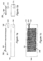
- the device 100 has a power-connector 101 which in this case is a socket.
- the apparatus 150 comprises a substantially flat power-receiving element 200, a layer of adhesive 201, a flexible connecting member (flexible wiring) 202 and a power-connector 203 capable of being plugged-in to the device's power-connector 101.
- Figures 1b and 1 show end and plan views of the arrangement of Figure 1a .
- the rear face (underside) of the mobile device 100 is uppermost in Figure 1a , and it is to this face that the element 200 is attached.
- Figures 2a to 2c shows corresponding views to those of Figures 1a to 1c but for apparatus 160 according to the second embodiment of the present invention.
- the device power connections (first connector means) 111a,b are contact strips instead of a socket.
- These device power connections 111a,b are adapted to connect to corresponding mating strips (second connector means - not shown) of external equipment (not shown) such as a charger.
- a power connector unit 213 of the apparatus has corresponding mating strips (third connector means) 215a,b on an inner face 214 thereof which make electrical contact with the device's power connections 111a,b.
- further connectors (fourth connector means) 217a,b are provided on an outer face 216 of the power connector unit 213 so that other equipment, for example an in-car hands-free unit or charger, having the second connector means may still be connected.
- These further connectors 217a,b are connected electrically to the corresponding contacts 215a,b by a pass-through connection arrangement incorporated into the power connector unit 213.
- the connectors 215a,b and 217a,b may include connectors used for purposes other than power delivery, for example input/output of signals and data.
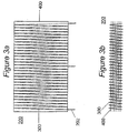
- FIGS 3a and 3b show plan and side views respectively of one example of a substantially flat power-receiving element 200 for use in embodiments of the present invention.
- a magnetic core consists of six strips of amorphous metal 400 each measuring 50x30x0.02mm, stacked. Around these is wound a coil 300, which could be for example of copper wire, tape, or a stamped or pressed metal. In this case, the coil passes around the core 30 times, with a centre-tap, providing current to three connections 202 which connect to further circuitry described later with reference to Figure 4 .
- the entire element is readily flexible, which is useful in making it conform to any non-flat part of the device to which it is applied, and also makes it less fragile, since the entire element can be less than 0.2mm thick.
- Figure 4 shows circuitry 450 capable of converting the alternating current delivered by the power receiving element into power suitable for, use in a portable electronic device.
- a parallel-resonating capacitor 501 tunes the coil, which allows increased power transfer.
- a value of 100's of nF is typical, depending on the exact core materials and coil construction, and therefore inductance.
- the alternating current is full-wave rectified by diodes 500. Schottky diodes with a forward voltage drop of 0.3V provide best performance.
- Capacitor 502 provides smoothing of the DC. The voltage at this point is unregulated, which may be sufficient to send to subsequent electronics within the portable device, if it is capable of taking such.
- Optional voltage regulator 503 limits the voltage for devices which are not capable of taking an unregulated supply. This regulator may be a linear or switch mode type, and may optionally also contain other protection and system management circuitry.
- Optional indicator 504 indicates that power is being received.
- the tuning capacitor may be parallel-resonant or series-resonant.
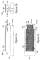
- Figure 5 shows a detail view of one implementation of a power connector 600.
- a barrel-shaped protrusion carries two conducting rings 601 and 602 which mate with contacts within the power input socket of the portable device.
- the circuitry 450 of Figure 4 is contained within the power connector, and the optional power indicator 504 is visible externally.
- the connector 600 is removable from an end 603 of the flexible wiring 202, allowing different power connectors to be fitted to suit the particular device, each with the appropriate circuitry (power electronics) 450.
- one end of the flexible wiring 202 could be removable from the power-receiving element 200 and the other end attached permanently to the power connector 600.
- the removable connections between the flexible wiring and the power connector and/or power-receiving element can be made by any suitable electrical connection arrangement such as a plug and socket.
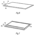
- the power-receiving element is in the form of a "sticker" 700.
- the element 700 has a layer of adhesive 702 on one surface 701 thereof.
- the element is supplied with a removable backing sheet 703 which protects the adhesive 702 prior to attachment of the element to the portable electrical device.
- the backing sheet 703 is peeled off by a user to expose the layer of adhesive 702 on surface 701. After peeling off the backing sheet 703 the user simply presses the power-receiving element on its adhesive side 702 to the portable electrical device.
- FIG. 7 shows a schematic perspective view of a power-receiving element in another embodiment of the present invention.
- the power-receiving element 800 has, on its side 801 which will be visible to a user when the element is attached to the device, a transparent pocket 802.
- the insert may bear text or pictures, for example a logo or advertising.
- apparatus embodying the present invention is in the form of a replacement cover portion of the portable electrical device itself.
- portable electrical device Commercially available which have replaceable cover portions.
- Handsets for use in mobile communications networks made by several major manufacturers are one example.
- Replacement cover portions for such devices can advantageously carry or incorporate at least the power-receiving element of apparatus embodying the present invention.
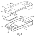
- FIG 8 shows a schematic perspective view of such a handset 900.
- the handset 900 has a battery compartment 902 for holding a removable battery pack 904.
- the removable battery pack 904 is, for example, a rechargeable battery pack.
- the battery pack 904 has terminals (not shown) which connect to corresponding battery connectors 906 of the handset 900 within the battery compartment 902 when the battery pack 904 is installed in the battery compartment.
- the handset 900 also has a power connector 908 at a bottom end 910 thereof.
- a replacement cover portion 950 is adapted to be fitted to the handset 900.
- the replacement cover portion in this embodiment is a rear cover portion and covers the battery compartment 902 of the handset 900 as well as other parts thereof.
- the cover portion 950 has on its inner face or incorporated within it a power-receiving element 952.
- the element 952 may, for example, be the same as the power-receiving element 200 described hereinbefore.
- the cover portion 950 is designed to extend at one end 954 beyond the bottom end 910 of the handset 900. At the end 954 the cover portion 950 has a power connector part 956 carrying one or more power connectors 958.
- the power connector(s) is/are connected in some suitable way (not shown) to the power-receiving element 952, either directly or via power conditioning circuitry such as the circuitry 450 of Figure 4 .
- the power connector(s) 958 is/are adapted to connect to the corresponding power connector(s) of the handset power connector 908.
- This arrangement is convenient in that installation of the cover portion 950 on the handset 900 automatically makes the required electrical connections between the power-receiving element 952 and the power connector 908 of the handset.
- the power connector part 956 of the cover portion 950 may be connected semi-rigidly (e.g. resiliently) instead of rigidly to the remaining parts of the cover portion 950. This can make it easier for the power connector(s) 958 of the cover portion to be connected to the corresponding power connector(s) of the handset 900 when the cover portion is being fitted to the handset.
- FIG 9 shows another embodiment in which the power-receiving element is carried by or incorporated in a replacement cover portion.
- a replacement cover portion 1000 does not have the extended end 954 or the power connector part 956 of the replacement cover portion 950 of Figure 8 .
- an internal power connector part 1002 is connected, preferably via power conditioning circuitry such as the circuitry 450 of Figure 4 , to the power-receiving element 952.
- the connection may be made using flexible wiring 1004.
- the power connector part 1002 is sufficiently thin to enable it to be interposed between the battery terminals of the battery pack 904 and the power connectors 906 formed within the battery compartment 902 of the handset 900.
- the power connector part 1002 has a set of contacts on both its main faces.
- the two sets of contacts are connected together by a pass-through connection arrangement. This enables the power from the battery pack 904 to be supplied to the power connectors 906 when the power-receiving element is not receiving power wirelessly from a transmitter.
- FIG 10 shows yet another embodiment in which a replacement cover portion 1050 carries or incorporates a rechargeable battery pack 1054 in addition to a power-receiving element 952.
- the electrical connections between the power receiving element 952 and the battery pack 1054 are made by suitable means (not shown) incorporated in or carried by the cover portion 1050.
- the fitting of the replacement cover portion 1050 to the handset 900 brings the battery terminals of the battery pack 1054 into contact with the power connectors 906 of the handset 900.
- the present application is a divisional application divided from EP03786118.4 (the "parent" application), which originated as PCT/GB2003/005470 .
- the wording of the original parent claims is provided here as the following set of statements. The applicant reserves the right to rely on this disclosure in the present application and in any divisional application divided from this application.
Landscapes
- Engineering & Computer Science (AREA)
- Theoretical Computer Science (AREA)
- Power Engineering (AREA)
- Computer Networks & Wireless Communication (AREA)
- General Physics & Mathematics (AREA)
- General Engineering & Computer Science (AREA)
- Physics & Mathematics (AREA)
- Signal Processing (AREA)
- Human Computer Interaction (AREA)
- Computer Hardware Design (AREA)
- Charge And Discharge Circuits For Batteries Or The Like (AREA)
- Telephone Set Structure (AREA)
- Power Sources (AREA)
Applications Claiming Priority (2)
| Application Number | Priority Date | Filing Date | Title |
|---|---|---|---|
| GBGB0229141.7A GB0229141D0 (en) | 2002-12-16 | 2002-12-16 | Improvements relating to contact-less power transfer |
| EP03786118.4A EP1573489B1 (de) | 2002-12-16 | 2003-12-16 | Anpassen von tragbaren elektrischen geräten zum empfang von drahtloser energie |
Related Parent Applications (2)
| Application Number | Title | Priority Date | Filing Date |
|---|---|---|---|
| EP03786118.4A Division-Into EP1573489B1 (de) | 2002-12-16 | 2003-12-16 | Anpassen von tragbaren elektrischen geräten zum empfang von drahtloser energie |
| EP03786118.4 Division | 2003-12-16 |
Publications (1)
| Publication Number | Publication Date |
|---|---|
| EP2330480A1 true EP2330480A1 (de) | 2011-06-08 |
Family
ID=9949665
Family Applications (5)
| Application Number | Title | Priority Date | Filing Date |
|---|---|---|---|
| EP10187345A Ceased EP2275897A3 (de) | 2002-12-16 | 2003-12-16 | Anpassung tragbarer elektrischer Vorrichtungen zum drahtlosen Leistungsempfang |
| EP03786118.4A Expired - Lifetime EP1573489B1 (de) | 2002-12-16 | 2003-12-16 | Anpassen von tragbaren elektrischen geräten zum empfang von drahtloser energie |
| EP10187342A Withdrawn EP2275895A3 (de) | 2002-12-16 | 2003-12-16 | Anpassung tragbarer elektrischer Vorrichtungen zum drahtlosen Leistungsempfang |
| EP11152593A Withdrawn EP2330480A1 (de) | 2002-12-16 | 2003-12-16 | Anpassung tragbarer elektrischer Vorrichtungen zum drahtlosen Leistungsempfang |
| EP10187343.8A Expired - Lifetime EP2275896B1 (de) | 2002-12-16 | 2003-12-16 | Anpassung tragbarer elektrischer Vorrichtungen zum drahtlosen Leistungsempfang |
Family Applications Before (3)
| Application Number | Title | Priority Date | Filing Date |
|---|---|---|---|
| EP10187345A Ceased EP2275897A3 (de) | 2002-12-16 | 2003-12-16 | Anpassung tragbarer elektrischer Vorrichtungen zum drahtlosen Leistungsempfang |
| EP03786118.4A Expired - Lifetime EP1573489B1 (de) | 2002-12-16 | 2003-12-16 | Anpassen von tragbaren elektrischen geräten zum empfang von drahtloser energie |
| EP10187342A Withdrawn EP2275895A3 (de) | 2002-12-16 | 2003-12-16 | Anpassung tragbarer elektrischer Vorrichtungen zum drahtlosen Leistungsempfang |
Family Applications After (1)
| Application Number | Title | Priority Date | Filing Date |
|---|---|---|---|
| EP10187343.8A Expired - Lifetime EP2275896B1 (de) | 2002-12-16 | 2003-12-16 | Anpassung tragbarer elektrischer Vorrichtungen zum drahtlosen Leistungsempfang |
Country Status (8)
| Country | Link |
|---|---|
| US (5) | US8055310B2 (de) |
| EP (5) | EP2275897A3 (de) |
| JP (2) | JP4925393B2 (de) |
| CN (1) | CN100347633C (de) |
| AU (1) | AU2003295117A1 (de) |
| GB (1) | GB0229141D0 (de) |
| HK (1) | HK1088086A1 (de) |
| WO (1) | WO2004055654A2 (de) |
Families Citing this family (269)
| Publication number | Priority date | Publication date | Assignee | Title |
|---|---|---|---|---|
| GB2399466B (en) * | 2003-03-10 | 2005-11-16 | Univ City Hong Kong | Battery charging system |
| US8917057B2 (en) | 2002-06-10 | 2014-12-23 | City University Of Hong Kong | Battery charging system |
| AU2003229145A1 (en) | 2002-06-10 | 2003-12-22 | City University Of Hong Kong | Planar inductive battery charger |
| US7982436B2 (en) * | 2002-12-10 | 2011-07-19 | Pure Energy Solutions, Inc. | Battery cover with contact-type power receiver for electrically powered device |
| US7932638B2 (en) * | 2002-12-10 | 2011-04-26 | Pure Energy Solutions, Inc. | Reliable contact and safe system and method for providing power to an electronic device |
| US20120080958A1 (en) * | 2002-12-10 | 2012-04-05 | Pure Energy Solutions, Inc. | Reliable contact and safe system and method for providing power to an electronic device |
| GB0229141D0 (en) | 2002-12-16 | 2003-01-15 | Splashpower Ltd | Improvements relating to contact-less power transfer |
| US10499465B2 (en) | 2004-02-25 | 2019-12-03 | Lynk Labs, Inc. | High frequency multi-voltage and multi-brightness LED lighting devices and systems and methods of using same |
| US10575376B2 (en) | 2004-02-25 | 2020-02-25 | Lynk Labs, Inc. | AC light emitting diode and AC LED drive methods and apparatus |
| WO2011143510A1 (en) | 2010-05-12 | 2011-11-17 | Lynk Labs, Inc. | Led lighting system |
| WO2006018229A1 (de) | 2004-08-16 | 2006-02-23 | Giesecke & Devrient Gmbh | Bidirektionaler, kontaktloser ladevorgang zwischen mehreren akkumulatoren |
| EP1782330B1 (de) * | 2004-08-16 | 2016-12-07 | Giesecke & Devrient GmbH | Gesteuertes kontaktloses aufladen eines akkumulators in einer chipkarte |
| US7970870B2 (en) | 2005-06-24 | 2011-06-28 | Microsoft Corporation | Extending digital artifacts through an interactive surface |
| US7825543B2 (en) | 2005-07-12 | 2010-11-02 | Massachusetts Institute Of Technology | Wireless energy transfer |
| CN102983639B (zh) | 2005-07-12 | 2016-01-27 | 麻省理工学院 | 无线非辐射能量传递 |
| US7514899B2 (en) | 2005-11-18 | 2009-04-07 | Avago Technologies Ecbu Ip (Singapore) Pte. Ltd. | Method and apparatus for optical wireless charging |
| GB0524790D0 (en) * | 2005-12-05 | 2006-01-11 | Univ City Hong Kong | Apparatus and method for the charging of electrical devices |
| FR2895164A1 (fr) * | 2005-12-19 | 2007-06-22 | France Telecom | Enveloppe et etui permettant la recharge d'un appareil electronique en situation de mobilite |
| US8447234B2 (en) | 2006-01-18 | 2013-05-21 | Qualcomm Incorporated | Method and system for powering an electronic device via a wireless link |
| US9130602B2 (en) | 2006-01-18 | 2015-09-08 | Qualcomm Incorporated | Method and apparatus for delivering energy to an electrical or electronic device via a wireless link |
| US11201500B2 (en) | 2006-01-31 | 2021-12-14 | Mojo Mobility, Inc. | Efficiencies and flexibilities in inductive (wireless) charging |
| US8169185B2 (en) | 2006-01-31 | 2012-05-01 | Mojo Mobility, Inc. | System and method for inductive charging of portable devices |
| US7952322B2 (en) | 2006-01-31 | 2011-05-31 | Mojo Mobility, Inc. | Inductive power source and charging system |
| JP4635918B2 (ja) * | 2006-03-13 | 2011-02-23 | ソニー株式会社 | 携帯電話機の保護カバーおよび携帯電話機の充電システム。 |
| US7812771B2 (en) * | 2006-03-22 | 2010-10-12 | Powercast, Llc | Method and apparatus for implementation of a wireless power supply |
| US11329511B2 (en) | 2006-06-01 | 2022-05-10 | Mojo Mobility Inc. | Power source, charging system, and inductive receiver for mobile devices |
| US7948208B2 (en) | 2006-06-01 | 2011-05-24 | Mojo Mobility, Inc. | Power source, charging system, and inductive receiver for mobile devices |
| JP4855150B2 (ja) * | 2006-06-09 | 2012-01-18 | 株式会社トプコン | 眼底観察装置、眼科画像処理装置及び眼科画像処理プログラム |
| US9129741B2 (en) | 2006-09-14 | 2015-09-08 | Qualcomm Incorporated | Method and apparatus for wireless power transmission |
| US7706771B2 (en) * | 2007-02-08 | 2010-04-27 | Broadcom Corporation | Inductive powering for a mobile communication device and method for use therewith |
| US9774086B2 (en) | 2007-03-02 | 2017-09-26 | Qualcomm Incorporated | Wireless power apparatus and methods |
| US8199117B2 (en) | 2007-05-09 | 2012-06-12 | Microsoft Corporation | Archive for physical and digital objects |
| US8805530B2 (en) | 2007-06-01 | 2014-08-12 | Witricity Corporation | Power generation for implantable devices |
| US9421388B2 (en) | 2007-06-01 | 2016-08-23 | Witricity Corporation | Power generation for implantable devices |
| US9124120B2 (en) | 2007-06-11 | 2015-09-01 | Qualcomm Incorporated | Wireless power system and proximity effects |
| TW200901599A (en) * | 2007-06-29 | 2009-01-01 | rong-cong Lin | Battery cover |
| CN101842962B (zh) | 2007-08-09 | 2014-10-08 | 高通股份有限公司 | 增加谐振器的q因数 |
| KR20120102173A (ko) * | 2007-09-13 | 2012-09-17 | 퀄컴 인코포레이티드 | 무선 전력 인가를 위한 안테나 |
| EP2188863A1 (de) * | 2007-09-13 | 2010-05-26 | QUALCOMM Incorporated | Maximierung des pulverertrags aus drahtlosen leistungsmagnetresonatoren |
| WO2009039113A1 (en) * | 2007-09-17 | 2009-03-26 | Nigel Power, Llc | Transmitters and receivers for wireless energy transfer |
| FI120853B (fi) * | 2007-09-18 | 2010-03-31 | Powerkiss Oy | Energiansiirtojärjestely ja -menetelmä |
| US11297705B2 (en) | 2007-10-06 | 2022-04-05 | Lynk Labs, Inc. | Multi-voltage and multi-brightness LED lighting devices and methods of using same |
| US11317495B2 (en) | 2007-10-06 | 2022-04-26 | Lynk Labs, Inc. | LED circuits and assemblies |
| KR101312215B1 (ko) | 2007-10-11 | 2013-09-27 | 퀄컴 인코포레이티드 | 자기 기계 시스템을 이용하는 무선 전력 전송 |
| RU2493579C2 (ru) * | 2007-10-17 | 2013-09-20 | Эксесс Бизнес Груп Интернейшнл Ллс | Беспроводные системы электропитания портативных компьютеров и электронных устройств |
| WO2009089184A2 (en) * | 2008-01-04 | 2009-07-16 | Mitch Randall | Device cover with embedded power receiver |
| EP2229614A1 (de) | 2008-01-07 | 2010-09-22 | Access Business Group International LLC | Drahtloser stromadapter für einen computer |
| US8367235B2 (en) * | 2008-01-18 | 2013-02-05 | Mophie, Inc. | Battery pack, holster, and extendible processing and interface platform for mobile devices |
| DE102008007822A1 (de) * | 2008-02-07 | 2009-08-13 | Fraunhofer-Gesellschaft zur Förderung der angewandten Forschung e.V. | Drahtlose Ladeschnittstelle für einen Energiespeicher |
| WO2009142795A1 (en) * | 2008-03-03 | 2009-11-26 | Mitch Randall | Apparatus and method for retrofitting a broad range of mobile devices to receive wireless power |
| US20100022285A1 (en) * | 2008-03-03 | 2010-01-28 | Wildcharge, Inc. | Apparatus and method for retrofitting a broad range of mobile devices to receive wireless power |
| US8629576B2 (en) | 2008-03-28 | 2014-01-14 | Qualcomm Incorporated | Tuning and gain control in electro-magnetic power systems |
| US20110050164A1 (en) | 2008-05-07 | 2011-03-03 | Afshin Partovi | System and methods for inductive charging, and improvements and uses thereof |
| US8629650B2 (en) | 2008-05-13 | 2014-01-14 | Qualcomm Incorporated | Wireless power transfer using multiple transmit antennas |
| US8878393B2 (en) | 2008-05-13 | 2014-11-04 | Qualcomm Incorporated | Wireless power transfer for vehicles |
| US8076801B2 (en) | 2008-05-14 | 2011-12-13 | Massachusetts Institute Of Technology | Wireless energy transfer, including interference enhancement |
| US7855529B2 (en) * | 2008-07-16 | 2010-12-21 | ConvenientPower HK Ltd. | Inductively powered sleeve for mobile electronic device |
| US9577436B2 (en) | 2008-09-27 | 2017-02-21 | Witricity Corporation | Wireless energy transfer for implantable devices |
| US8686598B2 (en) | 2008-09-27 | 2014-04-01 | Witricity Corporation | Wireless energy transfer for supplying power and heat to a device |
| US9035499B2 (en) | 2008-09-27 | 2015-05-19 | Witricity Corporation | Wireless energy transfer for photovoltaic panels |
| US8643326B2 (en) | 2008-09-27 | 2014-02-04 | Witricity Corporation | Tunable wireless energy transfer systems |
| US9318922B2 (en) | 2008-09-27 | 2016-04-19 | Witricity Corporation | Mechanically removable wireless power vehicle seat assembly |
| US8723366B2 (en) | 2008-09-27 | 2014-05-13 | Witricity Corporation | Wireless energy transfer resonator enclosures |
| US8901779B2 (en) | 2008-09-27 | 2014-12-02 | Witricity Corporation | Wireless energy transfer with resonator arrays for medical applications |
| US8946938B2 (en) | 2008-09-27 | 2015-02-03 | Witricity Corporation | Safety systems for wireless energy transfer in vehicle applications |
| US8466583B2 (en) | 2008-09-27 | 2013-06-18 | Witricity Corporation | Tunable wireless energy transfer for outdoor lighting applications |
| US8461721B2 (en) | 2008-09-27 | 2013-06-11 | Witricity Corporation | Wireless energy transfer using object positioning for low loss |
| US9093853B2 (en) | 2008-09-27 | 2015-07-28 | Witricity Corporation | Flexible resonator attachment |
| US8957549B2 (en) | 2008-09-27 | 2015-02-17 | Witricity Corporation | Tunable wireless energy transfer for in-vehicle applications |
| US8598743B2 (en) | 2008-09-27 | 2013-12-03 | Witricity Corporation | Resonator arrays for wireless energy transfer |
| US8963488B2 (en) | 2008-09-27 | 2015-02-24 | Witricity Corporation | Position insensitive wireless charging |
| US9246336B2 (en) | 2008-09-27 | 2016-01-26 | Witricity Corporation | Resonator optimizations for wireless energy transfer |
| US9601270B2 (en) | 2008-09-27 | 2017-03-21 | Witricity Corporation | Low AC resistance conductor designs |
| US8629578B2 (en) | 2008-09-27 | 2014-01-14 | Witricity Corporation | Wireless energy transfer systems |
| US9544683B2 (en) | 2008-09-27 | 2017-01-10 | Witricity Corporation | Wirelessly powered audio devices |
| US8304935B2 (en) | 2008-09-27 | 2012-11-06 | Witricity Corporation | Wireless energy transfer using field shaping to reduce loss |
| US8692412B2 (en) | 2008-09-27 | 2014-04-08 | Witricity Corporation | Temperature compensation in a wireless transfer system |
| US8587155B2 (en) | 2008-09-27 | 2013-11-19 | Witricity Corporation | Wireless energy transfer using repeater resonators |
| US8947186B2 (en) | 2008-09-27 | 2015-02-03 | Witricity Corporation | Wireless energy transfer resonator thermal management |
| US9184595B2 (en) | 2008-09-27 | 2015-11-10 | Witricity Corporation | Wireless energy transfer in lossy environments |
| US8922066B2 (en) | 2008-09-27 | 2014-12-30 | Witricity Corporation | Wireless energy transfer with multi resonator arrays for vehicle applications |
| US8324759B2 (en) | 2008-09-27 | 2012-12-04 | Witricity Corporation | Wireless energy transfer using magnetic materials to shape field and reduce loss |
| US8400017B2 (en) | 2008-09-27 | 2013-03-19 | Witricity Corporation | Wireless energy transfer for computer peripheral applications |
| US9744858B2 (en) | 2008-09-27 | 2017-08-29 | Witricity Corporation | System for wireless energy distribution in a vehicle |
| US8441154B2 (en) | 2008-09-27 | 2013-05-14 | Witricity Corporation | Multi-resonator wireless energy transfer for exterior lighting |
| US8669676B2 (en) | 2008-09-27 | 2014-03-11 | Witricity Corporation | Wireless energy transfer across variable distances using field shaping with magnetic materials to improve the coupling factor |
| US8461720B2 (en) | 2008-09-27 | 2013-06-11 | Witricity Corporation | Wireless energy transfer using conducting surfaces to shape fields and reduce loss |
| US8933594B2 (en) | 2008-09-27 | 2015-01-13 | Witricity Corporation | Wireless energy transfer for vehicles |
| US8482158B2 (en) | 2008-09-27 | 2013-07-09 | Witricity Corporation | Wireless energy transfer using variable size resonators and system monitoring |
| CA2738654C (en) | 2008-09-27 | 2019-02-26 | Witricity Corporation | Wireless energy transfer systems |
| US9160203B2 (en) | 2008-09-27 | 2015-10-13 | Witricity Corporation | Wireless powered television |
| US8461722B2 (en) | 2008-09-27 | 2013-06-11 | Witricity Corporation | Wireless energy transfer using conducting surfaces to shape field and improve K |
| US9396867B2 (en) | 2008-09-27 | 2016-07-19 | Witricity Corporation | Integrated resonator-shield structures |
| US8907531B2 (en) | 2008-09-27 | 2014-12-09 | Witricity Corporation | Wireless energy transfer with variable size resonators for medical applications |
| US8928276B2 (en) | 2008-09-27 | 2015-01-06 | Witricity Corporation | Integrated repeaters for cell phone applications |
| US8410636B2 (en) | 2008-09-27 | 2013-04-02 | Witricity Corporation | Low AC resistance conductor designs |
| US9601261B2 (en) | 2008-09-27 | 2017-03-21 | Witricity Corporation | Wireless energy transfer using repeater resonators |
| US8476788B2 (en) | 2008-09-27 | 2013-07-02 | Witricity Corporation | Wireless energy transfer with high-Q resonators using field shaping to improve K |
| US9065423B2 (en) | 2008-09-27 | 2015-06-23 | Witricity Corporation | Wireless energy distribution system |
| US9515494B2 (en) | 2008-09-27 | 2016-12-06 | Witricity Corporation | Wireless power system including impedance matching network |
| US9106203B2 (en) | 2008-09-27 | 2015-08-11 | Witricity Corporation | Secure wireless energy transfer in medical applications |
| US9601266B2 (en) | 2008-09-27 | 2017-03-21 | Witricity Corporation | Multiple connected resonators with a single electronic circuit |
| US8772973B2 (en) | 2008-09-27 | 2014-07-08 | Witricity Corporation | Integrated resonator-shield structures |
| US8692410B2 (en) | 2008-09-27 | 2014-04-08 | Witricity Corporation | Wireless energy transfer with frequency hopping |
| US8552592B2 (en) | 2008-09-27 | 2013-10-08 | Witricity Corporation | Wireless energy transfer with feedback control for lighting applications |
| US8901778B2 (en) | 2008-09-27 | 2014-12-02 | Witricity Corporation | Wireless energy transfer with variable size resonators for implanted medical devices |
| US8471410B2 (en) | 2008-09-27 | 2013-06-25 | Witricity Corporation | Wireless energy transfer over distance using field shaping to improve the coupling factor |
| US8937408B2 (en) | 2008-09-27 | 2015-01-20 | Witricity Corporation | Wireless energy transfer for medical applications |
| US8587153B2 (en) | 2008-09-27 | 2013-11-19 | Witricity Corporation | Wireless energy transfer using high Q resonators for lighting applications |
| US9105959B2 (en) | 2008-09-27 | 2015-08-11 | Witricity Corporation | Resonator enclosure |
| US8487480B1 (en) | 2008-09-27 | 2013-07-16 | Witricity Corporation | Wireless energy transfer resonator kit |
| US8569914B2 (en) | 2008-09-27 | 2013-10-29 | Witricity Corporation | Wireless energy transfer using object positioning for improved k |
| US8912687B2 (en) | 2008-09-27 | 2014-12-16 | Witricity Corporation | Secure wireless energy transfer for vehicle applications |
| US8497601B2 (en) | 2008-09-27 | 2013-07-30 | Witricity Corporation | Wireless energy transfer converters |
| WO2010039967A1 (en) | 2008-10-01 | 2010-04-08 | Massachusetts Institute Of Technology | Efficient near-field wireless energy transfer using adiabatic system variations |
| US8810194B2 (en) * | 2008-11-20 | 2014-08-19 | Qualcomm Incorporated | Retrofitting wireless power and near-field communication in electronic devices |
| JP5141518B2 (ja) * | 2008-11-28 | 2013-02-13 | 富士通株式会社 | 携帯端末装置 |
| EP2377296B1 (de) * | 2009-01-05 | 2019-10-16 | QUALCOMM Incorporated | Internes verbindungsschema zur ausstattung einer mobilen datenverarbeitungsvorrichtung mit abnehmbarem gehäusesegment |
| KR20110103395A (ko) * | 2009-02-05 | 2011-09-20 | 퀄컴 인코포레이티드 | 전자 디바이스의 무선 전력공급 및 근거리장 통신 개장 |
| US9312924B2 (en) | 2009-02-10 | 2016-04-12 | Qualcomm Incorporated | Systems and methods relating to multi-dimensional wireless charging |
| US20100201312A1 (en) | 2009-02-10 | 2010-08-12 | Qualcomm Incorporated | Wireless power transfer for portable enclosures |
| US8854224B2 (en) | 2009-02-10 | 2014-10-07 | Qualcomm Incorporated | Conveying device information relating to wireless charging |
| KR101083630B1 (ko) * | 2009-05-22 | 2011-11-17 | 정춘길 | 무접점 방식의 배터리 충전을 위한 제어모듈 배치 구조 |
| US9312728B2 (en) | 2009-08-24 | 2016-04-12 | Access Business Group International Llc | Physical and virtual identification in a wireless power network |
| US20110210617A1 (en) * | 2009-08-28 | 2011-09-01 | Pure Energy Solutions, Inc. | Power transmission across a substantially planar interface by magnetic induction and geometrically-complimentary magnetic field structures |
| KR101821904B1 (ko) | 2010-04-08 | 2018-01-24 | 액세스 비지니스 그룹 인터내셔날 엘엘씨 | Pos 유도성 시스템 및 방법 |
| TWI431887B (zh) * | 2010-05-21 | 2014-03-21 | Htc Corp | 與一電池相結合之無線充電封套及其相關無線充電系統 |
| CN102263425B (zh) * | 2010-05-28 | 2014-08-27 | 宏达国际电子股份有限公司 | 与电池相结合的无线充电封套及其相关无线充电系统 |
| WO2011156768A2 (en) | 2010-06-11 | 2011-12-15 | Mojo Mobility, Inc. | System for wireless power transfer that supports interoperability, and multi-pole magnets for use therewith |
| US20120106103A1 (en) * | 2010-06-23 | 2012-05-03 | Tanios Nohra | Radio frequency energy harvesting enclosure for radio frequency connected devices |
| KR101441453B1 (ko) * | 2010-08-25 | 2014-09-18 | 한국전자통신연구원 | 무선 에너지 전송을 위한 자기 공진체에서 전기장 및 복사전력 감소 장치 및 그 방법 |
| US9602168B2 (en) | 2010-08-31 | 2017-03-21 | Witricity Corporation | Communication in wireless energy transfer systems |
| US10010213B2 (en) * | 2010-11-02 | 2018-07-03 | Ember Technologies, Inc. | Heated or cooled dishware and drinkware and food containers |
| US9814331B2 (en) * | 2010-11-02 | 2017-11-14 | Ember Technologies, Inc. | Heated or cooled dishware and drinkware |
| US9035222B2 (en) * | 2010-11-02 | 2015-05-19 | Oromo Technologies, Inc. | Heated or cooled dishware and drinkware |
| US11950726B2 (en) | 2010-11-02 | 2024-04-09 | Ember Technologies, Inc. | Drinkware container with active temperature control |
| US8759721B1 (en) * | 2010-11-02 | 2014-06-24 | Piatto Technologies, Inc. | Heated or cooled dishwasher safe dishware and drinkware |
| WO2012061527A1 (en) * | 2010-11-02 | 2012-05-10 | Clayton Alexander | Heated or cooled dishwasher safe dishware and drinkware |
| CN102480149A (zh) * | 2010-11-29 | 2012-05-30 | 和硕联合科技股份有限公司 | 多功能背夹装置 |
| US9496732B2 (en) | 2011-01-18 | 2016-11-15 | Mojo Mobility, Inc. | Systems and methods for wireless power transfer |
| US10115520B2 (en) | 2011-01-18 | 2018-10-30 | Mojo Mobility, Inc. | Systems and method for wireless power transfer |
| US11342777B2 (en) | 2011-01-18 | 2022-05-24 | Mojo Mobility, Inc. | Powering and/or charging with more than one protocol |
| US9178369B2 (en) | 2011-01-18 | 2015-11-03 | Mojo Mobility, Inc. | Systems and methods for providing positioning freedom, and support of different voltages, protocols, and power levels in a wireless power system |
| US9356659B2 (en) | 2011-01-18 | 2016-05-31 | Mojo Mobility, Inc. | Chargers and methods for wireless power transfer |
| US20130293191A1 (en) | 2011-01-26 | 2013-11-07 | Panasonic Corporation | Non-contact charging module and non-contact charging instrument |
| DE112012000674T5 (de) * | 2011-02-03 | 2013-12-19 | Targus Group International, Inc. | Dockingstation für eine tragbare elektronische Einrichtung |
| CN102130482A (zh) * | 2011-03-21 | 2011-07-20 | 深圳桑菲消费通信有限公司 | 一种通用多功能无线充电套 |
| US20120244969A1 (en) | 2011-03-25 | 2012-09-27 | May Patents Ltd. | System and Method for a Motion Sensing Device |
| US9306411B2 (en) | 2011-06-14 | 2016-04-05 | Panasonic Intellectual Property Management Co., Ltd. | Electronic device including non-contact charging module |
| GB2508729B (en) * | 2011-06-22 | 2016-01-20 | Sandal Plc | Portable Charging Apparatus |
| US8660495B2 (en) * | 2011-07-05 | 2014-02-25 | Hewlett-Packard Development Company, L.P. | Accessory display system |
| US9948145B2 (en) | 2011-07-08 | 2018-04-17 | Witricity Corporation | Wireless power transfer for a seat-vest-helmet system |
| AU2012289855A1 (en) | 2011-08-04 | 2014-03-13 | Witricity Corporation | Tunable wireless power architectures |
| US20140239809A1 (en) | 2011-08-18 | 2014-08-28 | Lynk Labs, Inc. | Devices and systems having ac led circuits and methods of driving the same |
| US8909149B2 (en) * | 2011-08-26 | 2014-12-09 | Hewlett-Packard Development Company, L.P. | Media module of a device |
| WO2013031025A1 (ja) | 2011-09-02 | 2013-03-07 | 富士通株式会社 | 電力中継器 |
| EP2998153B1 (de) | 2011-09-09 | 2023-11-01 | WiTricity Corporation | Fremdkörpererkennung in drahtlosen energieübertragungssystemen |
| US20130062966A1 (en) | 2011-09-12 | 2013-03-14 | Witricity Corporation | Reconfigurable control architectures and algorithms for electric vehicle wireless energy transfer systems |
| KR101979266B1 (ko) * | 2011-09-30 | 2019-08-28 | 삼성전자주식회사 | 무선 충전 모듈을 구비하는 휴대용 단말기 |
| WO2013048053A1 (ko) * | 2011-09-30 | 2013-04-04 | 삼성전자주식회사 | 무선 충전 모듈을 구비하는 휴대용 단말기 |
| US9318257B2 (en) | 2011-10-18 | 2016-04-19 | Witricity Corporation | Wireless energy transfer for packaging |
| US9607757B2 (en) | 2011-11-02 | 2017-03-28 | Panasonic Corporation | Non-contact wireless communication coil, transmission coil, and portable wireless terminal |
| US10204734B2 (en) | 2011-11-02 | 2019-02-12 | Panasonic Corporation | Electronic device including non-contact charging module and near field communication antenna |
| CN103988391A (zh) | 2011-11-04 | 2014-08-13 | WiTricity公司 | 无线能量传输建模工具 |
| US9247597B2 (en) | 2011-12-02 | 2016-01-26 | Lynk Labs, Inc. | Color temperature controlled and low THD LED lighting devices and systems and methods of driving the same |
| US20140327398A1 (en) * | 2011-12-14 | 2014-11-06 | Nec Casio Mobile Communications, Ltd. | Portable terminal apparatus and method for adjusting rfid antenna resonance frequency |
| TW201330442A (zh) * | 2012-01-02 | 2013-07-16 | Primax Electronics Ltd | 無線充電傳輸裝置 |
| KR20130081620A (ko) | 2012-01-09 | 2013-07-17 | 주식회사 케이더파워 | 무선 충전 시스템용 수신기 |
| US9994066B2 (en) | 2012-01-24 | 2018-06-12 | Mitsubishi Pencil Company, Limited | Erasing implement and writing implement provided with erasing implement |
| JP2015508987A (ja) | 2012-01-26 | 2015-03-23 | ワイトリシティ コーポレーションWitricity Corporation | 減少した場を有する無線エネルギー伝送 |
| JP2013169122A (ja) | 2012-02-17 | 2013-08-29 | Panasonic Corp | 非接触充電モジュール及びそれを備えた携帯端末 |
| US9722447B2 (en) | 2012-03-21 | 2017-08-01 | Mojo Mobility, Inc. | System and method for charging or powering devices, such as robots, electric vehicles, or other mobile devices or equipment |
| US8774716B2 (en) * | 2012-03-29 | 2014-07-08 | Auden Techno Corp. | Mobile terminal extension case |
| US8684012B1 (en) * | 2012-05-31 | 2014-04-01 | Denise Lynn Ryan | Remote control rollers |
| US9343922B2 (en) | 2012-06-27 | 2016-05-17 | Witricity Corporation | Wireless energy transfer for rechargeable batteries |
| JP6112383B2 (ja) | 2012-06-28 | 2017-04-12 | パナソニックIpマネジメント株式会社 | 携帯端末 |
| JP6008237B2 (ja) | 2012-06-28 | 2016-10-19 | パナソニックIpマネジメント株式会社 | 携帯端末 |
| US9287607B2 (en) | 2012-07-31 | 2016-03-15 | Witricity Corporation | Resonator fine tuning |
| US9979206B2 (en) | 2012-09-07 | 2018-05-22 | Solace Power Inc. | Wireless electric field power transfer system, method, transmitter and receiver therefor |
| US9179558B1 (en) | 2012-09-17 | 2015-11-03 | Brite Case, LLC | Case with panel for display |
| US9595378B2 (en) | 2012-09-19 | 2017-03-14 | Witricity Corporation | Resonator enclosure |
| CN103022404B (zh) * | 2012-09-27 | 2015-05-27 | 珠海德百祺科技有限公司 | 移动终端和用于该移动终端的电池 |
| WO2014055658A2 (en) * | 2012-10-02 | 2014-04-10 | Witricity Corporation | Wireless power transfer |
| JP5737482B2 (ja) | 2012-10-17 | 2015-06-17 | 株式会社村田製作所 | ワイヤレス受電装置、ワイヤレス送電装置、及びワイヤレス送受電装置 |
| CN109969007A (zh) | 2012-10-19 | 2019-07-05 | 韦特里西提公司 | 无线能量传输系统中的外来物检测 |
| US11843260B2 (en) | 2012-11-09 | 2023-12-12 | California Institute Of Technology | Generator unit for wireless power transfer |
| US11616520B2 (en) | 2012-11-09 | 2023-03-28 | California Institute Of Technology | RF receiver |
| CN108390160B (zh) * | 2012-11-09 | 2021-04-27 | 加州理工学院 | 智能rf透镜效应:高效、动态和移动无线功率传输 |
| US9842684B2 (en) | 2012-11-16 | 2017-12-12 | Witricity Corporation | Systems and methods for wireless power system with improved performance and/or ease of use |
| US20160132457A1 (en) * | 2013-03-19 | 2016-05-12 | Hewlett Packard Development Company, L.P. | Interconnect assembly |
| US9837846B2 (en) | 2013-04-12 | 2017-12-05 | Mojo Mobility, Inc. | System and method for powering or charging receivers or devices having small surface areas or volumes |
| US9601267B2 (en) | 2013-07-03 | 2017-03-21 | Qualcomm Incorporated | Wireless power transmitter with a plurality of magnetic oscillators |
| WO2015021450A1 (en) * | 2013-08-08 | 2015-02-12 | Ramin Rostami | System, apparatus and method for generic electronic device power module and case formation |
| WO2015023899A2 (en) | 2013-08-14 | 2015-02-19 | Witricity Corporation | Impedance tuning |
| TWM469671U (zh) * | 2013-08-22 | 2014-01-01 | Kuo-Zhi Huang | 可被無線供電的電子裝置及其無線電力結構 |
| TWI509937B (zh) | 2013-09-16 | 2015-11-21 | 萬國商業機器公司 | 用於一第一裝置對一第二裝置進行無線充電的方法,充電裝置,及充電系統 |
| EP3072214B1 (de) | 2013-11-22 | 2018-10-10 | California Institute of Technology | Generatoreinheit zur drahtlosen stromübertragung |
| US9780573B2 (en) | 2014-02-03 | 2017-10-03 | Witricity Corporation | Wirelessly charged battery system |
| WO2015123614A2 (en) | 2014-02-14 | 2015-08-20 | Witricity Corporation | Object detection for wireless energy transfer systems |
| KR101762778B1 (ko) | 2014-03-04 | 2017-07-28 | 엘지이노텍 주식회사 | 무선 충전 및 통신 기판 그리고 무선 충전 및 통신 장치 |
| US9716861B1 (en) | 2014-03-07 | 2017-07-25 | Steelcase Inc. | Method and system for facilitating collaboration sessions |
| US10664772B1 (en) | 2014-03-07 | 2020-05-26 | Steelcase Inc. | Method and system for facilitating collaboration sessions |
| US20150270737A1 (en) * | 2014-03-21 | 2015-09-24 | Sony Corporation | Terminal device cover and a terminal device for contactless charging |
| US9842687B2 (en) | 2014-04-17 | 2017-12-12 | Witricity Corporation | Wireless power transfer systems with shaped magnetic components |
| US9892849B2 (en) | 2014-04-17 | 2018-02-13 | Witricity Corporation | Wireless power transfer systems with shield openings |
| US9837860B2 (en) | 2014-05-05 | 2017-12-05 | Witricity Corporation | Wireless power transmission systems for elevators |
| JP2017518018A (ja) | 2014-05-07 | 2017-06-29 | ワイトリシティ コーポレーションWitricity Corporation | 無線エネルギー伝送システムにおける異物検出 |
| US9766079B1 (en) | 2014-10-03 | 2017-09-19 | Steelcase Inc. | Method and system for locating resources and communicating within an enterprise |
| US9955318B1 (en) | 2014-06-05 | 2018-04-24 | Steelcase Inc. | Space guidance and management system and method |
| US9380682B2 (en) | 2014-06-05 | 2016-06-28 | Steelcase Inc. | Environment optimization for space based on presence and activities |
| US10433646B1 (en) | 2014-06-06 | 2019-10-08 | Steelcaase Inc. | Microclimate control systems and methods |
| US10614694B1 (en) | 2014-06-06 | 2020-04-07 | Steelcase Inc. | Powered furniture assembly |
| US11744376B2 (en) | 2014-06-06 | 2023-09-05 | Steelcase Inc. | Microclimate control systems and methods |
| WO2015196123A2 (en) | 2014-06-20 | 2015-12-23 | Witricity Corporation | Wireless power transfer systems for surfaces |
| SG11201610806QA (en) | 2014-06-26 | 2017-01-27 | Solace Power Inc | Wireless electric field power transmission system, transmitter and receiver therefor and method of wirelessly transferring power |
| US10574091B2 (en) | 2014-07-08 | 2020-02-25 | Witricity Corporation | Enclosures for high power wireless power transfer systems |
| WO2016007674A1 (en) | 2014-07-08 | 2016-01-14 | Witricity Corporation | Resonator balancing in wireless power transfer systems |
| EP3183797B1 (de) | 2014-08-19 | 2020-10-07 | California Institute of Technology | Drahtlose stromübertragung |
| US9852388B1 (en) | 2014-10-03 | 2017-12-26 | Steelcase, Inc. | Method and system for locating resources and communicating within an enterprise |
| EP3015950A1 (de) | 2014-10-28 | 2016-05-04 | Targus Group International, Inc. | Leistungs- und datenadapter sowie entsprechende systeme und verfahren |
| KR101628019B1 (ko) * | 2014-12-10 | 2016-06-13 | 오지훈 | 무선 충전 수신 모듈 |
| AU2015362706B2 (en) | 2014-12-15 | 2020-05-21 | Targus International Llc | Power and data adapter |
| US9843217B2 (en) | 2015-01-05 | 2017-12-12 | Witricity Corporation | Wireless energy transfer for wearables |
| US9782036B2 (en) | 2015-02-24 | 2017-10-10 | Ember Technologies, Inc. | Heated or cooled portable drinkware |
| USD861653S1 (en) | 2015-05-27 | 2019-10-01 | Mophie Inc. | Protective battery case for mobile communications device |
| US10733371B1 (en) | 2015-06-02 | 2020-08-04 | Steelcase Inc. | Template based content preparation system for use with a plurality of space types |
| US10027150B2 (en) * | 2015-06-18 | 2018-07-17 | Serene Devices Llc | RFI/EMI shielding enclosure containing wireless charging element for personal electronic devices security |
| US10248899B2 (en) | 2015-10-06 | 2019-04-02 | Witricity Corporation | RFID tag and transponder detection in wireless energy transfer systems |
| EP3362804B1 (de) | 2015-10-14 | 2024-01-17 | WiTricity Corporation | Phasen- und amplitudendetektion in systemen zur drahtlosen energieübertragung |
| US10063110B2 (en) | 2015-10-19 | 2018-08-28 | Witricity Corporation | Foreign object detection in wireless energy transfer systems |
| WO2017070009A1 (en) | 2015-10-22 | 2017-04-27 | Witricity Corporation | Dynamic tuning in wireless energy transfer systems |
| US10075019B2 (en) | 2015-11-20 | 2018-09-11 | Witricity Corporation | Voltage source isolation in wireless power transfer systems |
| US10263473B2 (en) | 2016-02-02 | 2019-04-16 | Witricity Corporation | Controlling wireless power transfer systems |
| US10063104B2 (en) | 2016-02-08 | 2018-08-28 | Witricity Corporation | PWM capacitor control |
| US10033203B1 (en) | 2016-02-10 | 2018-07-24 | James Frederick Snyder, Jr. | Apparatus and method for charging at least one portable electrical device |
| US10622824B2 (en) * | 2016-03-04 | 2020-04-14 | Logitech Europe S.A. | Wireless charging for an input device |
| DE102017002146A1 (de) | 2016-03-04 | 2017-09-07 | Logitech Europe S.A. | Drahtloses Laden für eine Eingabeeinrichtung |
| WO2017192396A1 (en) | 2016-05-02 | 2017-11-09 | Ember Technologies, Inc. | Heated or cooled drinkware |
| JP6522153B2 (ja) | 2016-05-12 | 2019-05-29 | エンバー テクノロジーズ, インコーポレイテッド | 飲料用容器及び食器並びに飲料用容器及び食器のためのアクティブ制御モジュール |
| US9921726B1 (en) | 2016-06-03 | 2018-03-20 | Steelcase Inc. | Smart workstation method and system |
| US10705566B2 (en) | 2016-09-09 | 2020-07-07 | Targus International Llc | Systems, methods and devices for native and virtualized video in a hybrid docking station |
| KR20180035662A (ko) | 2016-09-29 | 2018-04-06 | 엠버 테크놀로지스 인코포레이티드 | 가열되거나 냉각된 음료용기 |
| US9995529B1 (en) * | 2016-12-08 | 2018-06-12 | Nova Laboratories | Temperature-regulating containment system |
| US10264213B1 (en) | 2016-12-15 | 2019-04-16 | Steelcase Inc. | Content amplification system and method |
| US10720797B2 (en) | 2017-05-26 | 2020-07-21 | California Institute Of Technology | Method and apparatus for dynamic RF lens focusing and tracking of wireless power recovery unit |
| US10283952B2 (en) | 2017-06-22 | 2019-05-07 | Bretford Manufacturing, Inc. | Rapidly deployable floor power system |
| WO2019006376A1 (en) | 2017-06-29 | 2019-01-03 | Witricity Corporation | PROTECTION AND CONTROL OF WIRELESS POWER SYSTEMS |
| US10663498B2 (en) | 2017-07-20 | 2020-05-26 | Targus International Llc | Systems, methods and devices for remote power management and discovery |
| US11231448B2 (en) | 2017-07-20 | 2022-01-25 | Targus International Llc | Systems, methods and devices for remote power management and discovery |
| US11079077B2 (en) | 2017-08-31 | 2021-08-03 | Lynk Labs, Inc. | LED lighting system and installation methods |
| US20190110643A1 (en) * | 2017-10-14 | 2019-04-18 | Gloria Contreras | Smart charger plate |
| US10516431B2 (en) | 2017-11-21 | 2019-12-24 | Mophie Inc. | Mobile device case for receiving wireless signals |
| ES2959703T3 (es) | 2018-01-31 | 2024-02-27 | Ember Tech Inc | Sistema de biberón calentado o enfriado activamente |
| EP3781884A1 (de) | 2018-04-19 | 2021-02-24 | Ember Technologies, Inc. | Tragbarer kühler mit aktiver temperaturregelung |
| US11502536B2 (en) * | 2018-05-18 | 2022-11-15 | Bracketron, Inc. | Wireless charging mount |
| US11522382B1 (en) | 2018-08-03 | 2022-12-06 | William Vahle | Wireless mobile battery |
| US11239682B2 (en) | 2018-10-09 | 2022-02-01 | Can Cakmak | Wireless charging pack |
| BR112021011716A2 (pt) | 2018-12-19 | 2021-08-31 | Targus International Llc | Aparelho de exibição e acoplamento para um dispositivo eletrônico portátil |
| US11360534B2 (en) | 2019-01-04 | 2022-06-14 | Targus Internatonal Llc | Smart workspace management system |
| US11017334B2 (en) | 2019-01-04 | 2021-05-25 | Targus International Llc | Workspace management system utilizing smart docking station for monitoring power consumption, occupancy, and usage displayed via heat maps |
| JP7430728B2 (ja) | 2019-01-11 | 2024-02-13 | エンバー テクノロジーズ, インコーポレイテッド | 能動的温度制御を備える可搬式冷却器 |
| US11444485B2 (en) | 2019-02-05 | 2022-09-13 | Mojo Mobility, Inc. | Inductive charging system with charging electronics physically separated from charging coil |
| US11162716B2 (en) | 2019-06-25 | 2021-11-02 | Ember Technologies, Inc. | Portable cooler |
| US11668508B2 (en) | 2019-06-25 | 2023-06-06 | Ember Technologies, Inc. | Portable cooler |
| WO2020263710A1 (en) | 2019-06-25 | 2020-12-30 | Ember Technologies, Inc. | Portable cooler |
| AU2020333961A1 (en) | 2019-08-22 | 2022-02-24 | Targus International Llc | Systems and methods for participant-controlled video conferencing |
| CA3153964A1 (en) | 2019-09-09 | 2021-03-18 | Targus International Llc | Systems and methods for docking stations removably attachable to display apparatuses and docking stand assemblies |
| JP2022020270A (ja) * | 2020-07-20 | 2022-02-01 | 株式会社オートネットワーク技術研究所 | 車載装置および車載システム |
| US11984739B1 (en) | 2020-07-31 | 2024-05-14 | Steelcase Inc. | Remote power systems, apparatus and methods |
Citations (12)
| Publication number | Priority date | Publication date | Assignee | Title |
|---|---|---|---|---|
| US5455467A (en) * | 1991-12-18 | 1995-10-03 | Apple Computer, Inc. | Power connection scheme |
| WO1996002879A1 (en) * | 1994-07-19 | 1996-02-01 | Elonex Technologies, Inc. | Micro personal digital assistant |
| US5959433A (en) * | 1997-08-22 | 1999-09-28 | Centurion Intl., Inc. | Universal inductive battery charger system |
| JP2000166112A (ja) * | 1998-11-27 | 2000-06-16 | Matsushita Electric Ind Co Ltd | 移動情報端末装置の充電装置及び移動情報端末装置 |
| JP2001060998A (ja) * | 1999-08-20 | 2001-03-06 | Denso Corp | 携帯電話機の接続装置 |
| US6208115B1 (en) * | 1997-06-16 | 2001-03-27 | Yehuda Binder | Battery substitute pack |
| EP1117068A1 (de) * | 1998-08-31 | 2001-07-18 | C. Media Co. Ltd. | Kontaktlose ic-träger und system unter verwendung derselben |
| EP1221753A2 (de) * | 2001-01-05 | 2002-07-10 | Samsung Electronics Co., Ltd. | Kernloser superdünner PCB-Transformator und denselben gebrauchenden berührungslosen Batterielader |
| US20020099894A1 (en) * | 1997-06-26 | 2002-07-25 | Timothy Kehoe | Adapter unit having a handle grip for a personal digital assistant |
| WO2002095555A2 (en) * | 2001-05-18 | 2002-11-28 | Palm, Inc. | Portable computer system |
| WO2003096512A2 (en) | 2002-05-13 | 2003-11-20 | Splashpower Limited | Contact-less power transfer |
| WO2003105308A1 (en) * | 2002-01-11 | 2003-12-18 | City University Of Hong Kong | Planar inductive battery charger |
Family Cites Families (76)
| Publication number | Priority date | Publication date | Assignee | Title |
|---|---|---|---|---|
| US1221753A (en) * | 1916-04-06 | 1917-04-03 | Gen Electric | Electric locomotive. |
| US2133742A (en) * | 1935-07-31 | 1938-10-18 | Kerotest Mfg Company | Forged valve body and method of making same |
| US2130243A (en) * | 1935-08-12 | 1938-09-13 | Galvin Mfg Corp | Radio receiving set |
| US2095555A (en) * | 1935-09-23 | 1937-10-12 | Mayer William | Adjustable necktie and strip applicable thereto |
| US2108868A (en) * | 1935-10-28 | 1938-02-22 | Rumsey Junior Vehicle Company | Chariot vehicle |
| US2388716A (en) * | 1936-03-30 | 1945-11-13 | Odin Corp | Valve mechanism |
| US2284255A (en) * | 1939-08-19 | 1942-05-26 | Larsen Boles Tool Company | Choke |
| US2250066A (en) * | 1940-07-17 | 1941-07-22 | Central Commercial Co | Musical instrument |
| US2399466A (en) * | 1942-01-08 | 1946-04-30 | Rca Corp | Metalworking |
| US2389767A (en) * | 1943-09-01 | 1945-11-27 | Budd Edward G Mfg Co | Structural frame |
| US2388715A (en) * | 1944-01-29 | 1945-11-13 | Lillian T Smith | Window blind |
| US2389720A (en) * | 1944-06-06 | 1945-11-27 | Phillips B Drane | Diaphragm operated valve |
| US3075415A (en) * | 1959-05-04 | 1963-01-29 | Gustav H Dabringhaus | Machine for deep drilling |
| US3096361A (en) * | 1959-06-19 | 1963-07-02 | Basf Ag | Production of nitriles from alcohols |
| US3096512A (en) * | 1960-09-22 | 1963-07-02 | Tasker Instr Corp | Multiple symbol visual presentation |
| US3105308A (en) * | 1961-06-12 | 1963-10-01 | Acf Ind Inc | Pressure ratio simulator |
| US3938018A (en) * | 1974-09-16 | 1976-02-10 | Dahl Ernest A | Induction charging system |
| JPS5821967A (ja) | 1981-07-31 | 1983-02-09 | Toshiba Corp | 電子模写装置における模写信号供給回路 |
| US4424246A (en) | 1981-11-02 | 1984-01-03 | Raychem Corporation | Patch closure system |
| GB2108868A (en) | 1981-11-04 | 1983-05-25 | Burgess Power Tools Ltd | Spray guns |
| JPS58107498A (ja) | 1981-12-18 | 1983-06-27 | Fuji Photo Film Co Ltd | 帯状金属板の電解処理方法および装置 |
| DE3390182T1 (de) | 1982-09-03 | 1984-10-18 | Naučno-proizvodstvennoe ob"edinenie "Tulačermet", Tula | Windform zum Bodenblasen von Metall |
| US4894283A (en) | 1988-05-10 | 1990-01-16 | Ncr Corporation | Reuseable thermal transfer ribbon |
| US4941154A (en) | 1989-05-30 | 1990-07-10 | At&T Bell Laboratories | Trellis coding method and arrangement for fractional bit rates |
| DE9015899U1 (de) | 1990-11-22 | 1991-02-07 | Skf Gmbh, 8720 Schweinfurt, De | |
| JPH065231A (ja) | 1992-06-23 | 1994-01-14 | Sony Corp | コンバーゼンス補正装置 |
| JP3261205B2 (ja) * | 1993-04-14 | 2002-02-25 | 任天堂株式会社 | 充電式電源システムおよびそれに用いられる充電ユニット,バッテリーユニット |
| JP3011829B2 (ja) | 1993-06-30 | 2000-02-21 | 株式会社ケンウッド | スピーカの製造方法及び製造装置 |
| GB2284255A (en) | 1993-11-29 | 1995-05-31 | Hor Kuang Flashlight Bulb Fact | Control of decorative lighting set |
| JP3011829U (ja) | 1994-07-27 | 1995-06-06 | 株式会社三岡電機製作所 | 充電用電源接続装置 |
| WO1996018940A1 (en) * | 1994-12-16 | 1996-06-20 | Elonex Technologies, Inc. | Management of data before zero volt suspend in computer power management |
| JPH09190938A (ja) | 1996-01-09 | 1997-07-22 | Tdk Corp | 非接触型充電装置 |
| US6519463B2 (en) * | 1996-02-28 | 2003-02-11 | Tendler Cellular, Inc. | Location based service request system |
| CN1197319A (zh) * | 1996-12-23 | 1998-10-28 | 曾明楷 | 一种便携两用太阳能手持机电池充电器 |
| JP2990083B2 (ja) * | 1996-12-27 | 1999-12-13 | 静岡日本電気株式会社 | 移動通信用アンテナ装置 |
| US7068991B2 (en) * | 1997-05-09 | 2006-06-27 | Parise Ronald J | Remote power recharge for electronic equipment |
| JPH1141824A (ja) * | 1997-07-14 | 1999-02-12 | Casio Comput Co Ltd | 携帯型電子機器 |
| JP3747677B2 (ja) * | 1998-03-03 | 2006-02-22 | セイコーエプソン株式会社 | 電子機器 |
| US6275681B1 (en) * | 1998-04-16 | 2001-08-14 | Motorola, Inc. | Wireless electrostatic charging and communicating system |
| CN2350918Y (zh) * | 1998-12-31 | 1999-11-24 | 周伟中 | 随无线移动电话机携带式充电器 |
| US7518267B2 (en) | 2003-02-04 | 2009-04-14 | Access Business Group International Llc | Power adapter for a remote device |
| US6803744B1 (en) * | 1999-11-01 | 2004-10-12 | Anthony Sabo | Alignment independent and self aligning inductive power transfer system |
| JP2001251207A (ja) | 2000-03-07 | 2001-09-14 | Hitachi Ltd | 携帯電話機 |
| US6628459B2 (en) * | 2000-04-19 | 2003-09-30 | Olympus Optical Co., Ltd. | Focus stabilizing apparatus |
| JP2001352698A (ja) * | 2000-06-06 | 2001-12-21 | Funai Electric Co Ltd | 電源制御装置、電源制御システム、および、電子機器 |
| FI116344B (fi) * | 2000-10-11 | 2005-10-31 | Nokia Corp | Viestintälaite |
| JP3580245B2 (ja) * | 2000-11-10 | 2004-10-20 | 日本電気株式会社 | 携帯端末 |
| FI20002493A (fi) * | 2000-11-14 | 2002-05-15 | Salcomp Oy | Teholähdejärjestely ja induktiivisesti kytketty akkulaturi, jossa on langattomasti kytketty ohjaus, ja menetelmä teholähdejärjestelyn ja induktiivisesti kytketyn akkulaturin ohjaamiseksi langattomasti |
| US20020090983A1 (en) | 2001-01-11 | 2002-07-11 | I-Ming Chen | Device for charging a battery unit of a mobile telephone handset |
| JP2002288002A (ja) * | 2001-03-26 | 2002-10-04 | Mitsubishi Electric Corp | エミュレータ装置及びエミュレーション方法 |
| US20020148325A1 (en) * | 2001-04-13 | 2002-10-17 | Bergsma S. Craig | Semi-solid formed, low elongation aluminum alloy connecting rod |
| JP2002359676A (ja) * | 2001-05-31 | 2002-12-13 | Sanyodo:Kk | 携帯電話装置及び携帯電話装置用バッテリー |
| CN2480996Y (zh) | 2001-06-08 | 2002-03-06 | 徐跃进 | 手机锂电池太阳能充电装置 |
| US6977479B2 (en) * | 2002-01-08 | 2005-12-20 | Hsu Po-Jung John | Portable cell phone battery charger using solar energy as the primary source of power |
| GB0213374D0 (en) | 2002-06-10 | 2002-07-24 | Univ City Hong Kong | Planar inductive battery charger |
| GB2399466B (en) | 2003-03-10 | 2005-11-16 | Univ City Hong Kong | Battery charging system |
| US20030132731A1 (en) * | 2002-01-14 | 2003-07-17 | Asoka Inc. | Contactless battery charging device |
| US6913477B2 (en) * | 2002-03-01 | 2005-07-05 | Mobilewise, Inc. | Wirefree mobile device power supply method & system with free positioning |
| US7392068B2 (en) | 2002-03-01 | 2008-06-24 | Mobilewise | Alternative wirefree mobile device power supply method and system with free positioning |
| GB2388715B (en) | 2002-05-13 | 2005-08-03 | Splashpower Ltd | Improvements relating to the transfer of electromagnetic power |
| GB0213375D0 (en) | 2002-06-10 | 2002-07-24 | Univ City Hong Kong | Apparatus for energy transfer by induction |
| US7471062B2 (en) * | 2002-06-12 | 2008-12-30 | Koninklijke Philips Electronics N.V. | Wireless battery charging |
| AU2003258171A1 (en) | 2002-08-12 | 2004-02-25 | Mobilewise, Inc. | Wireless power supply system for small devices |
| US7430003B2 (en) * | 2002-08-23 | 2008-09-30 | Candid Color Systems, Inc. | Digital camera/computer synchronization method |
| US20040131928A1 (en) * | 2002-09-17 | 2004-07-08 | Tal Dayan | Modifying surfaces of devices to integrate them into wireless charging systems |
| US7440780B2 (en) * | 2002-09-18 | 2008-10-21 | University Of Pittsburgh - Of The Commonwealth System Of Higher Education | Recharging method and apparatus |
| US7056308B2 (en) * | 2002-10-04 | 2006-06-06 | Dsu Medical Corporation | Medical device with elastomeric penetrable wall and inner seal |
| US6756765B2 (en) * | 2002-10-08 | 2004-06-29 | Koninklijke Philips Electronics N.V. | System and method for charging users to recharge power supplies in portable devices |
| TW200419332A (en) | 2002-10-18 | 2004-10-01 | Mobilewise Inc | Small geometry pads and system for wireless power supply |
| US20040142726A1 (en) * | 2002-11-01 | 2004-07-22 | Tal Dayan | Method for controlling and interacting with a mobile device |
| GB0229141D0 (en) * | 2002-12-16 | 2003-01-15 | Splashpower Ltd | Improvements relating to contact-less power transfer |
| US7117010B2 (en) * | 2003-05-29 | 2006-10-03 | Cingular Wireless Ii, Llc | Wireless phone powered inductive loopset |
| US7378817B2 (en) * | 2003-12-12 | 2008-05-27 | Microsoft Corporation | Inductive power adapter |
| US7548040B2 (en) * | 2005-07-28 | 2009-06-16 | Zerog Wireless, Inc. | Wireless battery charging of electronic devices such as wireless headsets/headphones |
| US8447234B2 (en) * | 2006-01-18 | 2013-05-21 | Qualcomm Incorporated | Method and system for powering an electronic device via a wireless link |
| WO2009089184A2 (en) * | 2008-01-04 | 2009-07-16 | Mitch Randall | Device cover with embedded power receiver |
-
2002
- 2002-12-16 GB GBGB0229141.7A patent/GB0229141D0/en not_active Ceased
-
2003
- 2003-12-16 WO PCT/GB2003/005470 patent/WO2004055654A2/en active Application Filing
- 2003-12-16 US US10/539,062 patent/US8055310B2/en active Active
- 2003-12-16 EP EP10187345A patent/EP2275897A3/de not_active Ceased
- 2003-12-16 JP JP2004559903A patent/JP4925393B2/ja not_active Expired - Lifetime
- 2003-12-16 EP EP03786118.4A patent/EP1573489B1/de not_active Expired - Lifetime
- 2003-12-16 EP EP10187342A patent/EP2275895A3/de not_active Withdrawn
- 2003-12-16 AU AU2003295117A patent/AU2003295117A1/en not_active Abandoned
- 2003-12-16 CN CNB2003801061341A patent/CN100347633C/zh not_active Expired - Lifetime
- 2003-12-16 EP EP11152593A patent/EP2330480A1/de not_active Withdrawn
- 2003-12-16 EP EP10187343.8A patent/EP2275896B1/de not_active Expired - Lifetime
-
2006
- 2006-07-25 HK HK06108242A patent/HK1088086A1/xx not_active IP Right Cessation
-
2010
- 2010-04-05 JP JP2010087041A patent/JP5193249B2/ja not_active Expired - Lifetime
-
2011
- 2011-02-28 US US13/036,637 patent/US8280453B2/en not_active Expired - Lifetime
-
2012
- 2012-08-29 US US13/597,657 patent/US8560024B2/en not_active Expired - Lifetime
-
2013
- 2013-09-11 US US14/024,186 patent/US9112957B2/en not_active Expired - Lifetime
-
2015
- 2015-07-09 US US14/795,117 patent/US10007297B2/en active Active
Patent Citations (13)
| Publication number | Priority date | Publication date | Assignee | Title |
|---|---|---|---|---|
| US5455467A (en) * | 1991-12-18 | 1995-10-03 | Apple Computer, Inc. | Power connection scheme |
| WO1996002879A1 (en) * | 1994-07-19 | 1996-02-01 | Elonex Technologies, Inc. | Micro personal digital assistant |
| US6208115B1 (en) * | 1997-06-16 | 2001-03-27 | Yehuda Binder | Battery substitute pack |
| US20020099894A1 (en) * | 1997-06-26 | 2002-07-25 | Timothy Kehoe | Adapter unit having a handle grip for a personal digital assistant |
| US5959433A (en) * | 1997-08-22 | 1999-09-28 | Centurion Intl., Inc. | Universal inductive battery charger system |
| EP1117068A1 (de) * | 1998-08-31 | 2001-07-18 | C. Media Co. Ltd. | Kontaktlose ic-träger und system unter verwendung derselben |
| JP2000166112A (ja) * | 1998-11-27 | 2000-06-16 | Matsushita Electric Ind Co Ltd | 移動情報端末装置の充電装置及び移動情報端末装置 |
| JP2001060998A (ja) * | 1999-08-20 | 2001-03-06 | Denso Corp | 携帯電話機の接続装置 |
| EP1221753A2 (de) * | 2001-01-05 | 2002-07-10 | Samsung Electronics Co., Ltd. | Kernloser superdünner PCB-Transformator und denselben gebrauchenden berührungslosen Batterielader |
| WO2002095555A2 (en) * | 2001-05-18 | 2002-11-28 | Palm, Inc. | Portable computer system |
| WO2003105308A1 (en) * | 2002-01-11 | 2003-12-18 | City University Of Hong Kong | Planar inductive battery charger |
| WO2003096512A2 (en) | 2002-05-13 | 2003-11-20 | Splashpower Limited | Contact-less power transfer |
| WO2003096361A1 (en) | 2002-05-13 | 2003-11-20 | Splashpower Limited | Improvements relating to the transfer of electromagnetic power |
Also Published As
| Publication number | Publication date |
|---|---|
| CN1726450A (zh) | 2006-01-25 |
| JP4925393B2 (ja) | 2012-04-25 |
| EP1573489A2 (de) | 2005-09-14 |
| US9112957B2 (en) | 2015-08-18 |
| US20120319500A1 (en) | 2012-12-20 |
| JP2006510101A (ja) | 2006-03-23 |
| EP2275896B1 (de) | 2017-03-22 |
| CN100347633C (zh) | 2007-11-07 |
| AU2003295117A1 (en) | 2004-07-09 |
| US8055310B2 (en) | 2011-11-08 |
| HK1088086A1 (en) | 2006-10-27 |
| WO2004055654A3 (en) | 2004-09-23 |
| US8280453B2 (en) | 2012-10-02 |
| EP2275896A3 (de) | 2011-04-06 |
| WO2004055654A2 (en) | 2004-07-01 |
| JP2010213570A (ja) | 2010-09-24 |
| AU2003295117A8 (en) | 2004-07-09 |
| US8560024B2 (en) | 2013-10-15 |
| US20110210619A1 (en) | 2011-09-01 |
| EP2275896A2 (de) | 2011-01-19 |
| EP1573489B1 (de) | 2017-03-15 |
| EP2275895A2 (de) | 2011-01-19 |
| EP2275897A3 (de) | 2011-04-06 |
| EP2275897A2 (de) | 2011-01-19 |
| GB0229141D0 (en) | 2003-01-15 |
| JP5193249B2 (ja) | 2013-05-08 |
| US20150311745A1 (en) | 2015-10-29 |
| US20060205381A1 (en) | 2006-09-14 |
| US10007297B2 (en) | 2018-06-26 |
| EP2275895A3 (de) | 2011-04-06 |
| US20140011551A1 (en) | 2014-01-09 |
Similar Documents
| Publication | Publication Date | Title |
|---|---|---|
| US10007297B2 (en) | Adapting portable electrical devices to receive power wirelessly | |
| US8380998B2 (en) | Inductive receivers for electrical devices | |
| JP4852829B2 (ja) | 非接触電力伝送装置 | |
| US6589069B1 (en) | Wire reel having a universal serial bus connector capable of doing emergency charging work | |
| EP2400629A2 (de) | Aufladbare induktive Steckdose | |
| US20140203661A1 (en) | Inductive power receiver having dual mode connector for portable electrical devices | |
| CN109547593A (zh) | 电子设备 | |
| CN209896729U (zh) | 分体式无线充电装置 | |
| CN209963819U (zh) | 智能门锁供电电路及智能门锁 | |
| CN207625329U (zh) | 一种具有收纳功能的充电设备 | |
| CN215450205U (zh) | 指环扣 | |
| US20230336029A1 (en) | Wearable battery charging cradle | |
| CN210444053U (zh) | 一种无线充电宝 | |
| KR20000039991A (ko) | 휴대 통신 단말기와 퍼스널 컴퓨터간 데이타 공유장치 | |
| CN113489502A (zh) | 用于音频采集设备的数据传输设备 | |
| TWM241858U (en) | Portable power supply |
Legal Events
| Date | Code | Title | Description |
|---|---|---|---|
| PUAI | Public reference made under article 153(3) epc to a published international application that has entered the european phase |
Free format text: ORIGINAL CODE: 0009012 |
|
| AC | Divisional application: reference to earlier application |
Ref document number: 1573489 Country of ref document: EP Kind code of ref document: P |
|
| AK | Designated contracting states |
Kind code of ref document: A1 Designated state(s): AT BE BG CH CY CZ DE DK EE ES FI FR GB GR HU IE IT LI LU MC NL PT RO SE SI SK TR |
|
| STAA | Information on the status of an ep patent application or granted ep patent |
Free format text: STATUS: THE APPLICATION IS DEEMED TO BE WITHDRAWN |
|
| 18D | Application deemed to be withdrawn |
Effective date: 20111209 |