EP2330282B1 - Gasmotorsteuerung - Google Patents
Gasmotorsteuerung Download PDFInfo
- Publication number
- EP2330282B1 EP2330282B1 EP09817417.0A EP09817417A EP2330282B1 EP 2330282 B1 EP2330282 B1 EP 2330282B1 EP 09817417 A EP09817417 A EP 09817417A EP 2330282 B1 EP2330282 B1 EP 2330282B1
- Authority
- EP
- European Patent Office
- Prior art keywords
- cylinder
- temperature
- cylinders
- exhaust gas
- control
- Prior art date
- Legal status (The legal status is an assumption and is not a legal conclusion. Google has not performed a legal analysis and makes no representation as to the accuracy of the status listed.)
- Active
Links
Images


Classifications
-
- F—MECHANICAL ENGINEERING; LIGHTING; HEATING; WEAPONS; BLASTING
- F02—COMBUSTION ENGINES; HOT-GAS OR COMBUSTION-PRODUCT ENGINE PLANTS
- F02M—SUPPLYING COMBUSTION ENGINES IN GENERAL WITH COMBUSTIBLE MIXTURES OR CONSTITUENTS THEREOF
- F02M21/00—Apparatus for supplying engines with non-liquid fuels, e.g. gaseous fuels stored in liquid form
- F02M21/02—Apparatus for supplying engines with non-liquid fuels, e.g. gaseous fuels stored in liquid form for gaseous fuels
- F02M21/0218—Details on the gaseous fuel supply system, e.g. tanks, valves, pipes, pumps, rails, injectors or mixers
- F02M21/0248—Injectors
- F02M21/0278—Port fuel injectors for single or multipoint injection into the air intake system
-
- F—MECHANICAL ENGINEERING; LIGHTING; HEATING; WEAPONS; BLASTING
- F02—COMBUSTION ENGINES; HOT-GAS OR COMBUSTION-PRODUCT ENGINE PLANTS
- F02D—CONTROLLING COMBUSTION ENGINES
- F02D41/00—Electrical control of supply of combustible mixture or its constituents
- F02D41/30—Controlling fuel injection
- F02D41/32—Controlling fuel injection of the low pressure type
- F02D41/36—Controlling fuel injection of the low pressure type with means for controlling distribution
-
- F—MECHANICAL ENGINEERING; LIGHTING; HEATING; WEAPONS; BLASTING
- F02—COMBUSTION ENGINES; HOT-GAS OR COMBUSTION-PRODUCT ENGINE PLANTS
- F02B—INTERNAL-COMBUSTION PISTON ENGINES; COMBUSTION ENGINES IN GENERAL
- F02B19/00—Engines characterised by precombustion chambers
- F02B19/10—Engines characterised by precombustion chambers with fuel introduced partly into pre-combustion chamber, and partly into cylinder
- F02B19/1019—Engines characterised by precombustion chambers with fuel introduced partly into pre-combustion chamber, and partly into cylinder with only one pre-combustion chamber
- F02B19/108—Engines characterised by precombustion chambers with fuel introduced partly into pre-combustion chamber, and partly into cylinder with only one pre-combustion chamber with fuel injection at least into pre-combustion chamber, i.e. injector mounted directly in the pre-combustion chamber
-
- F—MECHANICAL ENGINEERING; LIGHTING; HEATING; WEAPONS; BLASTING
- F02—COMBUSTION ENGINES; HOT-GAS OR COMBUSTION-PRODUCT ENGINE PLANTS
- F02B—INTERNAL-COMBUSTION PISTON ENGINES; COMBUSTION ENGINES IN GENERAL
- F02B19/00—Engines characterised by precombustion chambers
- F02B19/12—Engines characterised by precombustion chambers with positive ignition
-
- F—MECHANICAL ENGINEERING; LIGHTING; HEATING; WEAPONS; BLASTING
- F02—COMBUSTION ENGINES; HOT-GAS OR COMBUSTION-PRODUCT ENGINE PLANTS
- F02D—CONTROLLING COMBUSTION ENGINES
- F02D19/00—Controlling engines characterised by their use of non-liquid fuels, pluralities of fuels, or non-fuel substances added to the combustible mixtures
- F02D19/02—Controlling engines characterised by their use of non-liquid fuels, pluralities of fuels, or non-fuel substances added to the combustible mixtures peculiar to engines working with gaseous fuels
- F02D19/021—Control of components of the fuel supply system
- F02D19/023—Control of components of the fuel supply system to adjust the fuel mass or volume flow
- F02D19/024—Control of components of the fuel supply system to adjust the fuel mass or volume flow by controlling fuel injectors
-
- F—MECHANICAL ENGINEERING; LIGHTING; HEATING; WEAPONS; BLASTING
- F02—COMBUSTION ENGINES; HOT-GAS OR COMBUSTION-PRODUCT ENGINE PLANTS
- F02D—CONTROLLING COMBUSTION ENGINES
- F02D35/00—Controlling engines, dependent on conditions exterior or interior to engines, not otherwise provided for
- F02D35/02—Controlling engines, dependent on conditions exterior or interior to engines, not otherwise provided for on interior conditions
- F02D35/027—Controlling engines, dependent on conditions exterior or interior to engines, not otherwise provided for on interior conditions using knock sensors
-
- F—MECHANICAL ENGINEERING; LIGHTING; HEATING; WEAPONS; BLASTING
- F02—COMBUSTION ENGINES; HOT-GAS OR COMBUSTION-PRODUCT ENGINE PLANTS
- F02D—CONTROLLING COMBUSTION ENGINES
- F02D41/00—Electrical control of supply of combustible mixture or its constituents
- F02D41/0025—Controlling engines characterised by use of non-liquid fuels, pluralities of fuels, or non-fuel substances added to the combustible mixtures
- F02D41/0027—Controlling engines characterised by use of non-liquid fuels, pluralities of fuels, or non-fuel substances added to the combustible mixtures the fuel being gaseous
-
- F—MECHANICAL ENGINEERING; LIGHTING; HEATING; WEAPONS; BLASTING
- F02—COMBUSTION ENGINES; HOT-GAS OR COMBUSTION-PRODUCT ENGINE PLANTS
- F02D—CONTROLLING COMBUSTION ENGINES
- F02D41/00—Electrical control of supply of combustible mixture or its constituents
- F02D41/008—Controlling each cylinder individually
- F02D41/0085—Balancing of cylinder outputs, e.g. speed, torque or air-fuel ratio
-
- F—MECHANICAL ENGINEERING; LIGHTING; HEATING; WEAPONS; BLASTING
- F02—COMBUSTION ENGINES; HOT-GAS OR COMBUSTION-PRODUCT ENGINE PLANTS
- F02D—CONTROLLING COMBUSTION ENGINES
- F02D41/00—Electrical control of supply of combustible mixture or its constituents
- F02D41/02—Circuit arrangements for generating control signals
- F02D41/04—Introducing corrections for particular operating conditions
-
- F—MECHANICAL ENGINEERING; LIGHTING; HEATING; WEAPONS; BLASTING
- F02—COMBUSTION ENGINES; HOT-GAS OR COMBUSTION-PRODUCT ENGINE PLANTS
- F02D—CONTROLLING COMBUSTION ENGINES
- F02D41/00—Electrical control of supply of combustible mixture or its constituents
- F02D41/02—Circuit arrangements for generating control signals
- F02D41/14—Introducing closed-loop corrections
- F02D41/1438—Introducing closed-loop corrections using means for determining characteristics of the combustion gases; Sensors therefor
- F02D41/1444—Introducing closed-loop corrections using means for determining characteristics of the combustion gases; Sensors therefor characterised by the characteristics of the combustion gases
- F02D41/1446—Introducing closed-loop corrections using means for determining characteristics of the combustion gases; Sensors therefor characterised by the characteristics of the combustion gases the characteristics being exhaust temperatures
-
- F—MECHANICAL ENGINEERING; LIGHTING; HEATING; WEAPONS; BLASTING
- F02—COMBUSTION ENGINES; HOT-GAS OR COMBUSTION-PRODUCT ENGINE PLANTS
- F02M—SUPPLYING COMBUSTION ENGINES IN GENERAL WITH COMBUSTIBLE MIXTURES OR CONSTITUENTS THEREOF
- F02M21/00—Apparatus for supplying engines with non-liquid fuels, e.g. gaseous fuels stored in liquid form
- F02M21/02—Apparatus for supplying engines with non-liquid fuels, e.g. gaseous fuels stored in liquid form for gaseous fuels
- F02M21/0218—Details on the gaseous fuel supply system, e.g. tanks, valves, pipes, pumps, rails, injectors or mixers
- F02M21/0248—Injectors
- F02M21/0275—Injectors for in-cylinder direct injection, e.g. injector combined with spark plug
-
- F—MECHANICAL ENGINEERING; LIGHTING; HEATING; WEAPONS; BLASTING
- F02—COMBUSTION ENGINES; HOT-GAS OR COMBUSTION-PRODUCT ENGINE PLANTS
- F02M—SUPPLYING COMBUSTION ENGINES IN GENERAL WITH COMBUSTIBLE MIXTURES OR CONSTITUENTS THEREOF
- F02M21/00—Apparatus for supplying engines with non-liquid fuels, e.g. gaseous fuels stored in liquid form
- F02M21/02—Apparatus for supplying engines with non-liquid fuels, e.g. gaseous fuels stored in liquid form for gaseous fuels
- F02M21/0218—Details on the gaseous fuel supply system, e.g. tanks, valves, pipes, pumps, rails, injectors or mixers
- F02M21/0284—Arrangement of multiple injectors or fuel-air mixers per combustion chamber
-
- F—MECHANICAL ENGINEERING; LIGHTING; HEATING; WEAPONS; BLASTING
- F02—COMBUSTION ENGINES; HOT-GAS OR COMBUSTION-PRODUCT ENGINE PLANTS
- F02B—INTERNAL-COMBUSTION PISTON ENGINES; COMBUSTION ENGINES IN GENERAL
- F02B43/00—Engines characterised by operating on gaseous fuels; Plants including such engines
-
- Y—GENERAL TAGGING OF NEW TECHNOLOGICAL DEVELOPMENTS; GENERAL TAGGING OF CROSS-SECTIONAL TECHNOLOGIES SPANNING OVER SEVERAL SECTIONS OF THE IPC; TECHNICAL SUBJECTS COVERED BY FORMER USPC CROSS-REFERENCE ART COLLECTIONS [XRACs] AND DIGESTS
- Y02—TECHNOLOGIES OR APPLICATIONS FOR MITIGATION OR ADAPTATION AGAINST CLIMATE CHANGE
- Y02T—CLIMATE CHANGE MITIGATION TECHNOLOGIES RELATED TO TRANSPORTATION
- Y02T10/00—Road transport of goods or passengers
- Y02T10/10—Internal combustion engine [ICE] based vehicles
- Y02T10/12—Improving ICE efficiencies
-
- Y—GENERAL TAGGING OF NEW TECHNOLOGICAL DEVELOPMENTS; GENERAL TAGGING OF CROSS-SECTIONAL TECHNOLOGIES SPANNING OVER SEVERAL SECTIONS OF THE IPC; TECHNICAL SUBJECTS COVERED BY FORMER USPC CROSS-REFERENCE ART COLLECTIONS [XRACs] AND DIGESTS
- Y02—TECHNOLOGIES OR APPLICATIONS FOR MITIGATION OR ADAPTATION AGAINST CLIMATE CHANGE
- Y02T—CLIMATE CHANGE MITIGATION TECHNOLOGIES RELATED TO TRANSPORTATION
- Y02T10/00—Road transport of goods or passengers
- Y02T10/10—Internal combustion engine [ICE] based vehicles
- Y02T10/30—Use of alternative fuels, e.g. biofuels
Definitions
- the present invention relates to a control system for a reciprocating gas engine using as a main fuel a gas fuel such as a natural gas or a city gas.
- a multi-cylinder gas engine used in power generation equipment, etc. is provided with fuel feed valves for injecting a gas fuel such that the fuel feed valves respectively correspond to the cylinders.
- Each fuel feed valve is drivably controlled to feed the gas fuel with a proper amount. In this way, the engine is operative under a desired load.
- an ignition timing is controlled as well as the control of a fuel feed amount.
- a knocking might occur.
- the fuel feeding is stopped or reduced.
- a control system for a gas engine which is configured to drivably control a fuel feed valve according to an exhaust gas temperature of each cylinder, in view of the fact that a load placed on the cylinder affects its exhaust gas temperature.
- This control system is configured to calculate an average value of exhaust gas temperatures of respective cylinders, reduce a fuel feed amount of a cylinder whose exhaust gas temperature is higher than the average value, and increase a fuel feed amount of a cylinder whose exhaust gas temperature is lower than the average value.
- the fuel feed amounts for all of the cylinders are controlled to be changed all together according to their exhaust gas temperatures.
- 4094380 Publication US 2004/0003805 A1 discloses an engine exhaust temperature controlling method. According to said method, the exhaust temperatures of the cylinders of the engine are sampled at predetermined intervals, an average of the exhaust temperatures is calculated, the load factor at this point is determined, the average exhaust temperature is compared with the exhaust temperature of each cylinder, and it is determined whether a temperature deviation is greater or smaller than a set deviation for that load factor. When the deviation is smaller, the exhaust temperature is within the set deviation and there is no need to adjust the fuel spray period. However, when the deviation is greater it is determined whether to increase or reduce the opening period of the electronic fuel spray valve.
- an object of the present invention is to suppress a variation in exhaust gas temperature between cylinders to equalize loads placed on the cylinders to make them close to an equal one and minimize interference with another control.
- the cylinders whose fuel feed amounts should be changed are limited to the higher-temperature cylinder of the first predetermined number including the cylinder whose exhaust gas temperature is highest and the lower-temperature cylinder of the second predetermined number including the cylinder whose exhaust gas temperature is lowest, and there is a cylinder whose fuel feed amount is not changed.
- This makes it possible to equalize the exhaust gas temperatures of the cylinders to make them close to an equal one while minimizing the number of cylinders whose fuel feed amounts should be changed.
- the controller may be configured to, in the load equalization control, calculate an average value of exhaust gas temperatures of the cylinders which are the controlled targets, and decide a change amount of the fuel feed amount of the higher-temperature cylinder of the first predetermined number based on a deviation between the average value and the exhaust gas temperature of the higher-temperature cylinder, and a change amount of the fuel feed amount corresponding to the lower-temperature cylinder of the second predetermined number, based on a deviation between the average value and the exhaust gas temperature of the lower-temperature cylinder.
- the fuel feed amount is decided according to the magnitude of the deviation with respect to the average value, the exhaust gas temperature of the cylinder whose fuel feed amount should be changed can be made closer to the average value effectively.
- the controller may be configured to, in the load equalization control, calculate an average value of exhaust gas temperatures of the cylinders which are the controlled targets; and the controller may be configured not to change the fuel feed amount of the higher-temperature cylinder of the first predetermined number if a deviation between the average value and the exhaust gas temperature of the higher-temperature cylinder is less than a predetermined value, and not to change the fuel feed amount of the lower-temperature cylinder of the second predetermined number if a deviation between the average value and the exhaust gas temperature of the lower-temperature cylinder is less than the predetermined value.
- the controller since the fuel feed amount of the cylinder whose exhaust gas temperature is significantly far from the average value, is changed, interference with another controller can be lessened.
- Each of the first predetermined number and the second predetermined number is 1. In such a configuration, since the fuel feed amount of the cylinder whose exhaust gas temperature is highest and the fuel feed amount of the cylinder whose exhaust gas temperature is lowest are changed, interference with another control may be further lessened.
- the controller may be configured to, in the load equalization control, select the higher-temperature cylinder of the first predetermined number, and the lower-temperature cylinder of the second predetermined number, among the cylinders which are the controlled targets, in every predetermined period, and to continue to change the fuel feed amounts of the selected cylinders for the predetermined period.
- the "period” refers to a range or time of a phase angle of the gas engine.
- the controller may be configured to execute fuel stop control for stopping fuel feeding to a cylinder in which misfires has occurred, for a predetermined period, and the cylinder which is a controlled target in the fuel stop control may be excluded from the candidates of the cylinders which are the controlled targets in the load equalization control.
- the controller may be configured to execute knocking prevention control for reducing a fuel feed amount of a cylinder in which knocking has occurred, for a predetermined period; and a cylinder which is a controlled target in the knocking prevention control is excluded from the candidates of the cylinders which are the controlled targets in the load equalization control.
- the cylinder whose exhaust gas temperature has been decreased as a result of the fuel stop control or the knocking prevention control is not selected as the controlled targets, and the lower-temperature cylinder of the second predetermined number is selected from cylinders in which misfire or knocking has not occurred. Therefore, it is possible to the load equalization control from being disordered by and interfered by the fuel stop control or the knocking prevention control.
- Fig. 1 is a view showing a configuration of a control system for a gas engine according to an embodiment of the present invention.
- the gas engine 1 is a reciprocating multi-cylinder four-cycle engine which uses as a main fuel a gas fuel such as a natural gas or a city gas, and is used as, for example, a prime mover of power generation equipment.
- a power generator 50 is coupled to an output shaft 2 of the gas engine 1. The power generator 50 generates an AC power based on a rotational output of the gas engine 1.
- An exhaust manifold 5 is coupled to cylinders 3 of the gas engine 1 via exhaust ports 4 (see Fig. 2 ), respectively, and exhaust gases from the respective exhaust ports 4 are collected in the exhaust manifold 5.
- a turbo charger 6 is coupled to an exhaust passage extending from the exhaust manifold 5, and a high-pressure air from the turbo charger 6 can be supplied to intake ports 7 (see Fig. 2 ).
- An exhaust bypass valve 8 is provided in the exhaust passage extending from the exhaust manifold 5 to control an intake-air pressure.
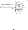
- Fig. 2 is a partial cross-sectional view of the gas engine 1 of Fig. 1 .
- Fig. 2 depicts a single cylinder as a representative but other cylinders have a similar configuration.
- a piston 9 is reciprocatably inserted into the cylinder 3.
- a main combustion chamber 10 is formed above the piston 9 inside the cylinder 3.
- the intake port 7 is coupled to the main combustion chamber 10 via intake valve(s) 11 and the exhaust port 4 is coupled to the main combustion chamber 10 via exhaust valve(s) 12.
- a main-fuel-feed valve 14 is provided inside the intake port 7 to inject the gas fuel.
- a sub-combustion chamber 15 is adjacent to the main combustion chamber 10.
- the sub-combustion chamber 15 is separated from the main combustion chamber 10 by a separating wall 16, and connects with the main combustion chamber 10 through a connection hole 17 formed in the separating wall 16.
- a sub-fuel-feed valve 18 for injecting a gas fuel and an ignition plug 19 for igniting an air-fuel mixture are provided.
- an air-fuel mixture containing outside air, the high-pressure air from the turbo charger 6 (see Fig. 1 ), and the gas fuel injected by the main-fuel-feed valve 14 is supplied to the main combustion chamber 10, via the intake port 6, while the air-fuel mixture containing the gas fuel injected by the sub-fuel-feed valve 18 is supplied to the sub-combustion chamber 15.
- the air-fuel mixture is compressed in the main combustion chamber 10 and in the sub-combustion chamber 15, and then the ignition plug 19 operates at a proper timing to ignite the air-fuel mixture in the sub-combustion chamber 15.
- a flame generated in the sub-combustion chamber 15 propagates to an interior of the main combustion chamber 10 through the connection hole 17, to ignite the air-fuel mixture in the main combustion chamber 10. Thereby, the piston 9 moves downward (expansion stroke). Then, in an exhaust stroke, a gas is exhausted from the main combustion chamber 10 to outside via the exhaust port 4.
- the gas engine 1 operates in such a manner that it goes through the above four strokes as one cycle.
- the piston 9 reciprocates twice, the output shaft 2 (see Fig. 1 ) rotates twice and a camshaft (not shown) constituting a valve system for driving the intake valve(s) 11 and the exhaust valve(s) 12 rotates once.
- a position of the piston 3, a rotational angle (crank angle) of the output shaft 2, a rotational angle of the camshaft, etc., during one cycle operation may be treated as a phase angle of the gas engine 1.
- the control system 20 for the gas engine 1 includes a main controller 21 for controlling an operation of the gas engine 1 totally.
- the main controller 21 includes a CPU, a memory, and an input/output interface. Control programs used for governor control, fuel stop control, knocking prevention control and load equalization control as described later are stored in the memory and are executed by the CPU.
- the main controller 21 is coupled to a gas valve controller 22 for outputting drive signals to the main-fuel-feed valve 14 and to the sub-fuel-feed valve 18, which are electromagnetic valves.
- the main controller 21 outputs command signals to the gas valve controller 22 to control valve open periods of the fuel feed valves 14 and 18, thereby controlling a fuel feed amount to the cylinder 3.
- the control for driving the fuel feed valves 14 and 18 is performed independently for each cylinder 3.
- the term "valve open periods” refer to periods from when the fuel feed valves 14 and 18 are excited to open until the fuel feed valves 14 and 18 are demagnetized to close. During the valve open periods, the fuel feed valves 14 and 18 inject the gas fuel. As the valve open periods are longer, the amount of the fuel fed to the cylinder 3 increases.
- the main controller 21 is coupled to an ignition plug driver 23 for outputting a drive signal to the ignition plug 19.
- the main controller 21 outputs a command signal to the driver 23, thereby driving the ignition plug 19.
- the control system 20 includes a phase angle detector 24 for detecting a phase angle of the gas engine 1 to control the valve open periods of the fuel feed valves 14 and 18 and an ignition timing of the air-fuel mixture by the ignition plug 14 .
- Signals from the phase angle detector 24 are input to the main controller 21, the gas valve controller 22 and the ignition plug driver 23.
- the phase angle detector 24 may be constituted by an electromagnetic pickup, a proximity switch or a rotary encoder.
- the control system 20 includes a knocking detector 25 to control the fuel feed amount to the cylinder 3 according to a combustion state of the gas engine 1.
- the phase angle detector 24 and a cylinder internal pressure sensor 26 for detecting an internal pressure of the cylinder 3 are coupled to the knocking detector 25.
- the knocking detector 25 determines whether a combustion state in the cylinder 3 is "normal”, “misfire”, “light knocking”, or “ heavy knocking” in each cycle based on the phase angle of the gas engine 1 and a pressure fluctuation in the interior of the cylinder 3. "heavy knocking” indicates that a knocking with a predetermined intensity or higher, which places a relatively large burden on the corresponding cylinder, has occurred, based on the internal fluctuation in the cylinder 3.
- the cylinder internal pressure sensor 26 is provided individually for each cylinder 3.
- the knocking detector 25 determines the combustion state of each cylinder 3 individually.
- the main controller 21 receives as an input a result of determination made by the knocking detector 25.
- the control system 20 includes an exhaust gas temperature sensor 27 to control the fuel feed amount to the cylinder 3 according to an exhaust gas temperature.
- a detection signal from the exhaust gas temperature sensor 27 is input to the main controller 21.
- the exhaust gas temperature sensor 27 is provided for each exhaust port 4, and the exhaust gas temperature of each cylinder 3 is input to the main controller 21.
- the main controller 21 receives an output of the power generator 50, an intake-air pressure detected by an air-intake sensor 28, etc.
- the main controller 21 controls an opening degree of the exhaust bypass valve so that a predetermined intake-air pressure is attained with respect to the output of the power generator 50, thereby maintaining an air-fuel ratio of the air-fuel mixture at a predetermined value according to the output of the power generator 50.
- the gas valve controller 22 controls a pressure of the gas fuel so that a pressure difference between the intake-air pressure and the pressure of the gas fuel reaches a predetermined value, thereby allowing the main-fuel-feed valve 14 to open and close stably regardless of a magnitude of the intake-air pressure.
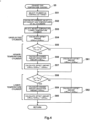
- Fig. 3 is a flowchart showing a control content executed by the main controller 21.
- steps S1 to S6 shown in Fig. 3 are performed repetitively every predetermined minute time (e.g., 10msec) for calculation. However, for the sale of simple explanation, it is assumed that calculation is repeated every one cycle.
- the main controller 21 executes governor control for deciding the valve open periods of the fuel feed valves 14 and 18 of each cylinder 3 so that the gas engine 1 is operated under a load according to a desired power generator output (step S1).
- the main controller 21 performs fuel stop control (step S2).
- An outline of the fuel stop control S2 is such that the valve open periods of the fuel feed valves 14 and 18 are set to zero during plural cycles to stop fuel feeding to a cylinder for which the knocking controller 25 determines that its combustion state is "misfire". This control can prevent a raw gas from releasing to outside continuously from a cylinder in which misfire occurred.
- the main controller 21 performs the knocking prevention control (step S3).
- An outline of the knocking prevention control S3 is such that the valve open periods of the fuel feed valves 14 and 18 are made shorter than those decided in the governor control S1 during the plural cycles for a cylinder for which the knocking controller 25 determines that its combustion state is "heavy knocking", thereby reducing the fuel feed amount to the cylinder.
- This control allows an air-fuel ratio of the air-fuel mixture in the cylinder in which the heavy knocking has occurred, to shift to one in which a fuel is lean, thereby suppressing occurrence of the knocking.
- step S4 It is determined whether or not cycles of a predetermined cycle number N have lapsed (step S4). If it is determined that the cycles of the predetermined cycle number N have not lapsed, command values of the valve open periods of the fuel feed valves 14 and 18 of the cylinders are calculated according to results of the above control S1 to S3 (step S6), and the fuel feed valves 14 and 18 are driven based on these command values. If it is determined that the cycles of the predetermined cycle number N have lapsed, then the main controller 21 executes load equalization control (step S5). In step S6, the command values of the valve open periods of the fuel feed valves 14 and 18 are calculated, according to results of the governor control S1, the fuel stop control S2, the knocking prevention control S3 and the load equalization control S5.
- the load equalization control S5 is executed after a lapse of every period of predetermined cycle number N. This can ensure a period in which the exhaust gas temperature is changed to a desired one. In addition, it is possible to prevent the fuel feed amount from being changed frequently based on the exhaust gas temperature and to stabilize a behavior of the gas engine 1.
- Fig. 3 depicts that the governor control S1, the fuel stop control S2 and the knocking prevention control S3 are performed every one cycle
- the control S1 to control S3 may be performed after a lapse of every predetermined period more than one cycle.
- the content of the fuel stop control S2 may be changed such that if a number of cycles in which misfire occurs for a predetermined period exceeds a predetermined threshold, the corresponding cylinder may be selected as a controlled target.
- the "predetermined period" may be equal to or different from the predetermined cycle number N used in the determination process in step S4.
- the content of the knocking prevention control S3 may be changed in the same manner.
- Fig. 4 is a flowchart showing a control content of the load equalization control S5 of Fig. 3 .
- Fig. 5 is a functional block diagram showing a configuration of the main controller 21 according to the content of load equalization control S5 of Fig. 4 .
- the load equalization control S5 is directed to make exhaust gas temperatures T #k of the respective cylinders close to an equal one to make the loads imposed on the respective cylinders close to an equal one.
- An outline of the load equalization control S5 is such that the valve open periods of the fuel feed valves 14 and 18 corresponding to a cylinder whose exhaust gas temperature T #k is higher, among the cylinders which are the controlled targets, are made shorter to reduce the fuel feed amount to the cylinder, and the valve open periods of the fuel feed valves 14 and 18 corresponding a cylinder whose exhaust gas temperature T #k is lower, among the cylinders which are the controlled targets, are made longer to increase the fuel feed amount to the cylinder.
- a part of all of the cylinders are selected as the higher-temperature cylinder whose fuel feed amount should be changed and as the lower-temperature cylinder whose fuel feed amount should be changed, and there is a cylinder whose fuel feed amount should not be changed.
- the main controller 21 includes as functional blocks, a governor controller 31 for performing the governor control S1, a fuel stop controller 32 for performing the fuel stop control S2, a knocking prevention controller 33 for performing the knocking prevention control S3, a load equalization controller 34 for performing the load equalization control S5 and a command value calculator 35 for calculating command values INJ #K of the valve open periods of the fuel feed valves 14 and 18.
- the load equalization controller 34 includes as functional blocks a controlled target selector 41, an average value calculator 42, a higher-temperature/lower-temperature cylinder selector 43 and an offset amount calculator 44.
- Reference symbol T #k indicates an exhaust gas temperature of k-th cylinder (# k) and reference symbol INJ #k indicates command values of the valve open periods of the fuel feed valves 14 and 18 of k-th cylinder (# k) (k: natural number of 1 to n, n: number of cylinders of the gas engine 1).
- the controlled target selector 41 in the main controller 21 excludes a cylinder which is a controlled target in the fuel stop control S2 in the fuel stop controller 32 and a cylinder which is a controlled target in the knocking prevention control S3 in the knocking prevention controller 33, from candidates of the cylinders which are controlled targets in the load equalization control S5 (step S51).
- FIG. 5 depicts a case where a third cylinder (# 3) is a controlled target of one of the control S2 and the control S3 and is excluded from the candidates of the cylinders which are controlled targets in the load equalization control S5, and also schematically shows that an exhaust gas temperature T #3 of the third cylinder is not considered in the following process of the load equalization control S5.
- valve open periods of the fuel feed valves 14 and 18 corresponding to the cylinder which is the controlled target in the fuel stop control S2 and the valve open periods of the fuel feed valves 14 and 18 corresponding to the cylinder which is the controlled target in the knocking prevention control S3 are shorter than those decided by the governor controller 31, and therefore their exhaust gas temperatures tend to be lower than ones under normal control. Therefore, prior to execution of the load equalization control S5, the cylinder whose exhaust gas temperature tends to be far from those of the cylinders which are the controlled targets in the load equalization control S5, is excluded preliminarily from the candidates of the cylinders which are controlled targets in the load equalization control S5. This makes it possible to prevent the load equalization control S5 from interfering with the fuel stop control S2 and the knocking prevention control S3.
- the average value calculator 42 in the main controller 21 calculates an average value T AVE of exhaust gas temperatures of all of the cylinders which are the controlled targets (step S52). In other words, in the example shown in Fig. 5 , in calculation of the average value T AVE , an exhaust gas temperature T #3 of the third cylinder (# 3) excluded from the candidates of the cylinders which are the controlled targets is not used.
- the higher-temperature/lower-temperature cylinder selector 43 in the main controller 21 extracts a maximum exhaust gas temperature (expressed as reference symbols T MAX1 ) from the exhaust gas temperatures of the cylinders which are the controlled targets and selects a cylinder corresponding to the extracted exhaust gas temperature as a higher-temperature cylinder (step S53).
- the higher-temperature/lower-temperature cylinder selector 43 in the main controller 21 extracts a minimum exhaust gas temperature (expressed as reference symbols T MIN1 from the exhaust gas temperatures of the cylinders which are controlled targets and selects a cylinder corresponding to the extracted exhaust gas temperature as a lower-temperature cylinder (step S53).
- FIG. 5 schematically depicts that, for example, an exhaust gas temperature T #1 of a first cylinder (#1) is the maximum value and the first cylinder is selected as the higher-temperature cylinder, while, for example, an exhaust gas temperature T #n-1 of a (n - 1)-th cylinder (#n - 1) is the minimum value and the (n - 1)-th cylinder is selected as the lower-temperature cylinder.
- the offset amount calculator 44 in the main controller 21 calculates offset amounts ⁇ INJ #k of a cylinder which is not selected as the higher-temperature/lower-temperature cylinder, among the cylinders which are controlled targets (step S54).
- the offset amounts ⁇ INJ #k are amounts used to change the command values INJ #k of the valve open periods of the fuel feed valves 14 and 18 with respect to the reference values INJ GVN decided by the governor controller 31.
- the offset amounts ⁇ INJ #k are changed and compensated properly when the corresponding cylinder is selected as the higher-temperature/lower-temperature cylinder.
- the offset amount calculator 44 in the main controller 21 determines whether or not an absolute value of a deviation between the exhaust gas temperature T MAX1 of the higher-temperature cylinder and the average value T AVE is larger than a predetermined threshold T SET_ MAX (step S55). If it is determined that the absolute value of the deviation is larger than a predetermined threshold T SET_ MAX , the offset amount calculator 44 multiples this absolute value by the predetermined gain to calculate change amounts ⁇ INJ MAX1 for changing and compensating the offset amounts ⁇ INJ #k of the valve open periods of the fuel feed valves 14 and 18 so that the offset amounts ⁇ INJ #k are shorter (step S56).
- the offset amount calculator 44 in the main controller 21 determines whether or not an absolute value of a deviation between the average value T AVE and the exhaust gas temperature T MINI1 of the lower-temperature cylinder is larger than the predetermined threshold T SET _ MIN (step S58). If it is determined the absolute value of the deviation is larger than the predetermined threshold T SET_MIN , the offset amount calculator 44 derives the change amount ⁇ INJ MIN1 for changing and compensating the offset amounts ⁇ INJ #k of the valve open periods of the fuel feed valves 14 and 18 by multiplying this absolute value by a predetermined gain (step S59).
- the absolute value of the deviation is not more than the threshold T SET_ MIN , the process moves to step S62.
- step S52 and step S53 is not limited to that shown in Fig. 4 , but may be reversed. The same applies to a relationship among step S54, step group S55 to S57 and step group S58 to S60.
- the command value calculator 35 in the main controller 21 calculates command values INJ #k of the valve open periods of the fuel feed valves 14 and 18 of each cylinder 3 based on reference values INJ GVN decided by the governor controller 31, the above offset amounts ⁇ INJ #k and control results of the fuel stop controller 32 and the knocking prevention controller 33 (step S6).
- the exhaust gas temperature of the higher-temperature cylinder decreases because the fuel feed amount is changed and compensated to decrease in the load equalization control S5 executed in the present case, while the exhaust gas temperature of the lower-temperature cylinder increases because the fuel feed amount is changed and compensated to increase in the load equalization control S5 executed in the present case.
- the exhaust gas temperatures of the respective cylinders 3 are made close to an equal one and the loads placed on the cylinders 3 are made close to an equal one.
- the change amount ⁇ INJ MAX1 of the fuel feed amount of the higher-temperature cylinder and the change amount ⁇ INJ MIN1 of the fuel feed amount of the lower-temperature cylinder are each decided as a deviation between the exhaust gas temperature of the cylinder and the average value T AVE .
- the above gains used to calculate the change amount ⁇ INJ MAX1 and the change amounts ⁇ INJ MIN1 , respectively, are preset properly so that the exhaust gas temperature of the higher-temperature cylinder and the exhaust gas temperature of the lower-temperature cylinder can be made close to the average value T AVE effectively.
- the offset amounts ⁇ INJ #k of even the cylinder selected as the higher-temperature/lower-temperature cylinder is not changed from the previous offset amounts ⁇ INJ #k ', if a deviation between its exhaust gas temperature and the average value is not more than the threshold. Therefore, the corresponding command values INJ #k are not changed from the command values set during a period from when the previous load equalization control S5 is initiated until when the present load equalization control S5 is initiated.
- the offset amounts ⁇ INJ #k of the cylinder which is not selected as the higher-temperature/lower-temperature cylinder are not changed from the offset amounts ⁇ INJ #k ' decided previously, the corresponding command values INJ #k (in the example shown in Fig. 5 , INJ #2 , INJ #4 , INJ #n ) are not changed from the command values set during a period from when the previous load equalization control S5 is initiated until the present load equalization control S5 is initiated.
- the command values INJ #k (in the example shown in Fig. 5 , INJ #3 ) are decided according to the change amounts decided in the control S2 or S3 and the reference values INJ GVN decided by the governor controller 31.
- the main controller 21 outputs a control signal to the gas valve controller 22, so that the valve open periods of the fuel feed valves 14 and 18 of each cylinder 3 reach ones according to the command values INJ #k .
- the fuel feed valves 14 and 18 continue to be driven in accordance with these command values during a period until next load equalization control S5 is initiated after a lapse of the cycles of the predetermined cycle number N.
- the load equalization control S5 is initiated, it is executed again along a flow shown in Fig. 4 , after a lapse of the cycles of the predetermined cycle number N. Thereby, the higher-temperature/lower-temperature cylinder is updated, and the command values INJ #k of the valve open periods are updated.
- the change amounts ⁇ INJ MAX1 and ⁇ INJ MIN1 continue to be included in the offset amounts decided in the next and following load equalization control S5 executed. Since the gas engine 1 continues to be operated for a long time while repeating the above load equalization control S5 many times, the exhaust gas temperatures of the cylinders are equalized and made close to an equal one and the loads placed on the respective cylinders are equalized and made close to an equal one.
- the number of cylinder whose fuel feed amount is increased according to the exhaust gas temperature in every period of the predetermined cycle number N and the number of cylinder whose fuel feed amount is decreased according to the exhaust gas temperature in every period of the predetermined cycle number N are each set to 1.
- the exhaust gas temperatures of the cylinders are made close to an equal one to make the loads placed on the cylinders close to an equal one and an advantage that interference between the load equalization control S5 and the governor control S1 is minimized can be both achieved.
- control system 20 for the gas engine 1 of the present invention has been described above, the above configuration may be changed suitably so long as it is within the scope of the present invention as defined in the appended claims.
- control system 20 may be configured to suppress the fuel feed amounts corresponding to all of the cylinders from being changed according to the exhaust gas temperatures, and to select a cylinder whose exhaust gas temperature is significantly far from the average value without fail, as the cylinder whose fuel feed amount should be changed.
- the number of cylinder selected as the higher-temperature cylinder and the number of cylinder selected as the lower-temperature cylinder may be preset so that a sum of them is at least less than the number of all cylinders.
- several cylinders including a cylinder whose exhaust gas temperature is highest, more preferably, several cylinders whose exhaust gas temperatures are higher in decreasing order from the highest temperature may be selected as higher-temperature cylinders
- several cylinders including a cylinder whose exhaust gas temperature is lowest more preferably, several cylinders whose exhaust gas temperatures are lower in increasing order from the lowest temperature may be selected as lower-temperature cylinders.
- both of the above advantages could be achieved. Since interference between the load equalization control S5 and the governor control S1 is lessened as the number of cylinder whose fuel feed amount is changed is made less. Therefore, the configuration of the above embodiment is able to lessen the interference most effectively.
- the load equalization control S5 the higher-temperature/lower-temperature cylinders are selected and the average value T AVE is calculated by using the exhaust gas temperature T #k detected in the cycle just after a lapse of the cycles of the predetermined cycle number N, the exhaust gas temperatures T #k of the respective cylinders which are detected for the cycles of the predetermined cycle number N are averaged , and the subsequent process may be performed using the averaged exhaust gas temperature.
- the load equalization control S5 can be executed stably.
- the fuel feed valve whose valve open period should be changed in the load equalization control S5 may be either one of the main-fuel-feed valve 14 and the sub-fuel-feed valve 18.
- a so-called a sub-combustion chamber and spark ignition method in which the ignition plug 19 ignites the air-fuel mixture in the sub-combustion chamber 15 is used as a method for igniting the air-fuel mixture
- other method may be used.
- a so-called pilot fuel injection method may be used, in which a gas engine is provided with a pilot fuel injection valve for injecting a high-pressure gas fuel and the high-pressure gas fuel is injected by the pilot fuel injection valve to a compressed air-fuel mixture in the combustion chamber.
- gas engine 1 is not limited to the prime mover in the power generation equipment but may be prime movers in other facilities or apparatuses.
- the present invention achieves advantages that a variation in exhaust gas temperature between cylinders is suppressed to equalize loads placed on the cylinders to make them close to an equal one, and interference with control being executed for another purpose is lessened.
- the present invention is particularly suitably applied to a gas engine used as a prime mover in power generation equipment.
Landscapes
- Engineering & Computer Science (AREA)
- Chemical & Material Sciences (AREA)
- Combustion & Propulsion (AREA)
- Mechanical Engineering (AREA)
- General Engineering & Computer Science (AREA)
- Chemical Kinetics & Catalysis (AREA)
- General Chemical & Material Sciences (AREA)
- Oil, Petroleum & Natural Gas (AREA)
- Electrical Control Of Air Or Fuel Supplied To Internal-Combustion Engine (AREA)
- Combined Controls Of Internal Combustion Engines (AREA)
- Output Control And Ontrol Of Special Type Engine (AREA)
Claims (4)
- Steuersystem für einem Gasmotor (1), umfassend:einen Abgastemperaturdetektor (27) zum Erfassen von Abgastemperaturen (T) einer Vielzahl von Zylindern (3) in dem Gasmotor;Kraftstoffzufuhrvorrichtungen (14, 18), die jeweils der Vielzahl von Zylindern entsprechen; eine Steuerung (21) zum Antreiben der Kraftstoffzufuhrvorrichtungen; undeinen Klopfdetektor (25), der mit einem Motorphasenwinkeldetektor (24) und mit einem Zylinderinnendrucksensor (26) gekoppelt ist und konfiguriert ist, um für jeden der Zylinder (3) zu bestimmen, ob darin eine Fehlzündung aufgetreten ist;wobei die Steuerung (21) so konfiguriert ist, dass sie eine Lastausgleichssteuerung (S5) in jeder Periode einer vorbestimmten Zyklusanzahl ausführt, so dass ein Durchschnittswert (TAVE) von Abgastemperaturen der Zylinder (3), die die gesteuerten Ziele sind, berechnet wird, und so dass eine Kraftstoffzufuhrmenge reduziert wird, die einem Zylinder mit höherer Temperatur einer ersten vorbestimmten Anzahl entspricht, der ausgewählt ist, um einen Zylinder mit der höchsten Abgastemperatur unter den Zylindern, die gesteuerte Ziele sind, zu umfassen, basierend auf der Abweichung zwischen der Abgastemperatur des Zylinders mit höherer Temperatur und dem Durchschnittswert, und eine Kraftstoffzuführmenge erhöht wird, die einem Zylinder mit niedrigerer Temperatur einer zweiten vorbestimmten Anzahl entspricht, die ausgewählt ist, um einen Zylinder mit der niedrigsten Abgastemperatur unter den Zylindern, die die gesteuerten Ziele sind, zu umfassen, basierend auf der Abweichung zwischen dem Durchschnittswert und der Abgastemperatur des Zylinders mit der niedrigeren Temperatur, wobei die Summe der ersten und zweiten vorbestimmten Anzahl kleiner als die Anzahl der Zylinder ist, so dass es zumindest einen Zylinder gibt, dessen Kraftstoffzufuhrmenge nicht geändert wird,wobei die Steuerung (21) so konfiguriert ist, dass sie gleichzeitig mit der Lastausgleichssteuerung (S5) eine Kraftstoffstoppsteuerung (S2) zum Stoppen der Kraftstoffzufuhr an einen Zylinder (3), in dem Fehlzündungen aufgetreten sind, für einen vorbestimmten Zeitraum ausführt, undwobei ein Zylinder (3), der ein gesteuertes Ziel in der Kraftstoffstoppsteuerung (S2) ist, von den Kandidaten der Zylinder ausgeschlossen wird, die die gesteuerten Ziele in der Lastausgleichssteuerung (S5) sind.
- Steuersystem für den Gasmotor nach Anspruch 1, wobeidie Steuerung (21) konfiguriert ist, um in der Lastausgleichssteuerung (S5) einen Durchschnittswert (TAVE) von Abgastemperaturen der Zylinder (3) zu berechnen, die die gesteuerten Ziele sind, unddie Steuerung (21) so konfiguriert ist, dass sie die Kraftstoffzufuhrmenge des Zylinders mit der höheren Temperatur nicht ändert, wenn eine Abweichung zwischen dem Durchschnittswert und der Abgastemperatur des Zylinders mit höherer Temperatur kleiner als ein vorbestimmter Wert ist, und die Kraftstoffzufuhrmenge des Zylinders mit der niedrigeren Temperatur nicht zu ändern, wenn eine Abweichung zwischen dem Durchschnittswert und der Abgastemperatur des Zylinders mit niedrigerer Temperatur kleiner als der vorbestimmte Wert ist.
- Steuersystem für den Gasmotor nach Anspruch 1, wobei
die Steuerung (21) so konfiguriert ist, dass sie in der Lastausgleichssteuerung den Zylinder mit der höheren Temperatur und den Zylinder mit der niedrigeren Temperatur unter den Zylindern (3), die die gesteuerten Ziele sind, in jeder vorbestimmten Zeitspanne auswählt, und die Kraftstoffzufuhrmengen der ausgewählten Zylinder für die vorbestimmte Zeitspanne weiter ändert. - Steuersystem für den Gasmotor nach Anspruch 1, wobeider Klopfdetektor (25) so konfiguriert ist, dass er für jeden der Zylinder (3) bestimmt, ob darin ein Klopfen aufgetreten ist;die Steuerung (21) so konfiguriert ist, dass sie eine Klopfverhinderungssteuerung zum Reduzieren einer Kraftstoffzufuhrmenge eines Zylinders (3), in dem ein Klopfen aufgetreten ist, für eine vorbestimmte Zeitspanne ausführt; undein Zylinder (3), der ein gesteuertes Ziel in der Klopfverhinderungssteuerung (S3) ist, von den Kandidaten der Zylinder ausgeschlossen wird, die die gesteuerten Ziele in der Lastausgleichssteuerung (S5) sind.
Applications Claiming Priority (2)
| Application Number | Priority Date | Filing Date | Title |
|---|---|---|---|
| JP2008256097A JP4688916B2 (ja) | 2008-10-01 | 2008-10-01 | ガスエンジンの制御装置 |
| PCT/JP2009/004687 WO2010038374A1 (ja) | 2008-10-01 | 2009-09-17 | ガスエンジンの制御装置 |
Publications (3)
| Publication Number | Publication Date |
|---|---|
| EP2330282A1 EP2330282A1 (de) | 2011-06-08 |
| EP2330282A4 EP2330282A4 (de) | 2016-08-24 |
| EP2330282B1 true EP2330282B1 (de) | 2023-04-26 |
Family
ID=42073158
Family Applications (1)
| Application Number | Title | Priority Date | Filing Date |
|---|---|---|---|
| EP09817417.0A Active EP2330282B1 (de) | 2008-10-01 | 2009-09-17 | Gasmotorsteuerung |
Country Status (7)
| Country | Link |
|---|---|
| US (1) | US20110214649A1 (de) |
| EP (1) | EP2330282B1 (de) |
| JP (1) | JP4688916B2 (de) |
| KR (1) | KR101239451B1 (de) |
| CN (1) | CN102171432B (de) |
| FI (1) | FI2330282T3 (de) |
| WO (1) | WO2010038374A1 (de) |
Families Citing this family (19)
| Publication number | Priority date | Publication date | Assignee | Title |
|---|---|---|---|---|
| JP5659380B2 (ja) * | 2010-07-01 | 2015-01-28 | 新潟原動機株式会社 | 予混合式ガスエンジンの空燃比補正制御方法および装置 |
| DE202012002091U1 (de) * | 2012-03-02 | 2012-07-09 | Peter Feldgebel | Vorrichtung zur Steuerung einer sequentiellen Gasanlage für Dieselmotoren |
| JP5962171B2 (ja) * | 2012-04-24 | 2016-08-03 | スズキ株式会社 | 車両の内燃機関の燃焼状態制御装置 |
| JP6028967B2 (ja) * | 2012-07-31 | 2016-11-24 | 国立研究開発法人 海上・港湾・航空技術研究所 | ガスエンジン用燃料噴射装置及びそれを搭載したガスエンジン装置 |
| DE102012021778B4 (de) * | 2012-11-06 | 2016-03-10 | Mtu Friedrichshafen Gmbh | Gemischaufgeladener Gasmotor und Verfahren zur Kompensation von Liefergradabweichungen in einem gemischaufgeladenen Gasmotor |
| JP5951537B2 (ja) | 2013-03-19 | 2016-07-13 | 三菱重工業株式会社 | ガスエンジンの燃焼制御装置 |
| JP2014181659A (ja) * | 2013-03-21 | 2014-09-29 | Yanmar Co Ltd | 火花点火式ガスエンジン |
| JP6025640B2 (ja) | 2013-03-28 | 2016-11-16 | 三菱重工業株式会社 | エンジンの失火時負荷制御方法およびその失火時負荷制御システム |
| US10107214B2 (en) * | 2013-10-31 | 2018-10-23 | Robert Bosch Gmbh | Control system and method using exhaust gas temperatures to adjust an air/fuel mixture for an internal combustion engine |
| US9334846B2 (en) * | 2014-02-07 | 2016-05-10 | Ford Global Technologies, Llc | Method and system of controlling bank to bank component temperature protection during individual cylinder knock control |
| EP2907993B1 (de) * | 2014-02-13 | 2019-11-06 | Caterpillar Motoren GmbH & Co. KG | Verfahren zur Zylindergleichstellung einer Brennkraftmaschine |
| AT517206B1 (de) * | 2015-06-30 | 2016-12-15 | Ge Jenbacher Gmbh & Co Og | Verfahren zur Regelung einer Brennkraftmaschine |
| CN106481468B (zh) * | 2015-08-27 | 2019-07-05 | 长城汽车股份有限公司 | 发动机的控制方法、系统及车辆 |
| US9644548B2 (en) * | 2015-10-02 | 2017-05-09 | GM Global Technology Operations LLC | Exhaust system pressure estimation systems and methods |
| US9657670B2 (en) * | 2015-10-02 | 2017-05-23 | GM Global Technology Operations LLC | Exhaust system temperature estimation systems and methods |
| CN109306914B (zh) * | 2018-09-26 | 2022-06-28 | 潍柴动力股份有限公司 | 一种大缸径发动机控制方法及装置 |
| CN112377316B (zh) * | 2020-12-01 | 2023-11-10 | 广西玉柴船电动力有限公司 | 一种双侧进气的v型燃气机的进气控制方法及进气系统 |
| DE102023203441A1 (de) * | 2023-04-17 | 2024-10-17 | Robert Bosch Gesellschaft mit beschränkter Haftung | Verfahren und Vorrichtung zur Regelung eines Drucks eines gasförmigen Brennstoffs in einer Brennkraftmaschine sowie Computerprogrammprodukt |
| JP2025018644A (ja) * | 2023-07-27 | 2025-02-06 | ヤンマーホールディングス株式会社 | エンジン装置及びエンジン装置の制御方法 |
Family Cites Families (17)
| Publication number | Priority date | Publication date | Assignee | Title |
|---|---|---|---|---|
| JPS62186037A (ja) * | 1986-02-10 | 1987-08-14 | Toyota Motor Corp | 内燃機関の燃料噴射装置 |
| JPH02245433A (ja) * | 1989-03-17 | 1990-10-01 | Toyota Motor Corp | 車両の加速スリップ制御装置 |
| JP3162553B2 (ja) * | 1993-09-13 | 2001-05-08 | 本田技研工業株式会社 | 内燃機関の空燃比フィードバック制御装置 |
| JPH10110640A (ja) * | 1996-10-04 | 1998-04-28 | Niigata Eng Co Ltd | 気筒間の燃焼バランス制御装置及び方法 |
| DE19825990A1 (de) * | 1998-06-10 | 1999-12-16 | Fev Motorentech Gmbh | Verfahren zur Erkennung von Zündaussetzern an einer Kolbenbrennkraftmaschine mit elektromagnetisch betätigbaren Gaswechselventilen |
| US6520159B2 (en) * | 2001-03-26 | 2003-02-18 | General Motors Corporation | Engine converter misfire protection method and apparatus |
| JP4094380B2 (ja) | 2001-08-29 | 2008-06-04 | 新潟原動機株式会社 | エンジン、エンジンの排気温度制御装置及び制御方法、コンピュータをエンジンの排気温度制御手段として機能させるためのプログラム |
| KR20040029304A (ko) * | 2001-08-29 | 2004-04-06 | 니이가타 겐도키 가부시키가이샤 | 엔진, 엔진의 배기온도 제어장치 및 제어방법 |
| JP4000952B2 (ja) * | 2002-08-13 | 2007-10-31 | いすゞ自動車株式会社 | 燃料噴射制御装置 |
| JP2004278461A (ja) * | 2003-03-18 | 2004-10-07 | Toyota Motor Corp | 内燃機関のノッキング制御装置 |
| JP2005155339A (ja) * | 2003-11-20 | 2005-06-16 | Toyota Motor Corp | 内燃機関の制御装置 |
| US7028670B2 (en) * | 2004-03-05 | 2006-04-18 | Ford Global Technologies, Llc | Torque control for engine during cylinder activation or deactivation |
| FI119395B (fi) * | 2004-03-15 | 2008-10-31 | Waertsilae Finland Oy | Adaptiivinen kuormantasausjärjestelmä |
| JP4488509B2 (ja) * | 2004-10-07 | 2010-06-23 | ヤンマー株式会社 | ガスエンジン |
| US7069911B1 (en) * | 2005-01-26 | 2006-07-04 | General Motors Corporation | Apparatus and methods for protecting a catalytic converter from misfire |
| JP4755155B2 (ja) * | 2007-08-30 | 2011-08-24 | 三菱重工業株式会社 | ガスエンジンの統合制御方法及び装置 |
| FI121031B (fi) * | 2008-03-31 | 2010-06-15 | Waertsilae Finland Oy | Säätöjärjestelmä ja menetelmä kaasua käyttävän polttomoottorin sylinterien tasapainottamiseksi |
-
2008
- 2008-10-01 JP JP2008256097A patent/JP4688916B2/ja active Active
-
2009
- 2009-09-17 US US13/122,142 patent/US20110214649A1/en not_active Abandoned
- 2009-09-17 KR KR1020117002219A patent/KR101239451B1/ko active Active
- 2009-09-17 EP EP09817417.0A patent/EP2330282B1/de active Active
- 2009-09-17 FI FIEP09817417.0T patent/FI2330282T3/fi active
- 2009-09-17 WO PCT/JP2009/004687 patent/WO2010038374A1/ja not_active Ceased
- 2009-09-17 CN CN2009801382477A patent/CN102171432B/zh active Active
Also Published As
| Publication number | Publication date |
|---|---|
| EP2330282A4 (de) | 2016-08-24 |
| EP2330282A1 (de) | 2011-06-08 |
| FI2330282T3 (fi) | 2023-07-25 |
| US20110214649A1 (en) | 2011-09-08 |
| KR101239451B1 (ko) | 2013-03-06 |
| WO2010038374A1 (ja) | 2010-04-08 |
| JP2010084680A (ja) | 2010-04-15 |
| CN102171432A (zh) | 2011-08-31 |
| CN102171432B (zh) | 2013-10-16 |
| JP4688916B2 (ja) | 2011-05-25 |
| KR20110036095A (ko) | 2011-04-06 |
Similar Documents
| Publication | Publication Date | Title |
|---|---|---|
| EP2330282B1 (de) | Gasmotorsteuerung | |
| US8783226B2 (en) | Knocking control system for gas engine | |
| US9140229B2 (en) | Knocking control system for gas engine | |
| US8983755B2 (en) | Control system and control method of gas engine | |
| EP2700804B1 (de) | Gasmotor, gasmotorsteuerungsvorrichtung und gasmotorsteuerungsverfahren | |
| JP6262957B2 (ja) | 内燃機関の運用方法 | |
| US20150226144A1 (en) | Method for balancing cylinders of an internal combustion engine | |
| WO2013008296A1 (ja) | 内燃機関の制御装置 | |
| EP3311016B1 (de) | Verfahren zum betrieb eines mehrzylindrigen kolbenmotors und kolbenmotor | |
| KR101575329B1 (ko) | 디젤 엔진 차량의 냉시동 제어 장치 및 방법 | |
| EP3399178B1 (de) | Gasmotorsystem | |
| EP2767703B1 (de) | Steuerungsvorrichtung für einen verbrennungsmotor | |
| JP6477619B2 (ja) | 内燃機関の制御装置 | |
| KR20160035072A (ko) | 내연기관 작동 방법 | |
| JP6570504B2 (ja) | 内燃機関の制御装置 | |
| JP2015014229A (ja) | 内燃機関の異常燃焼回避装置 |
Legal Events
| Date | Code | Title | Description |
|---|---|---|---|
| PUAI | Public reference made under article 153(3) epc to a published international application that has entered the european phase |
Free format text: ORIGINAL CODE: 0009012 |
|
| 17P | Request for examination filed |
Effective date: 20110317 |
|
| AK | Designated contracting states |
Kind code of ref document: A1 Designated state(s): AT BE BG CH CY CZ DE DK EE ES FI FR GB GR HR HU IE IS IT LI LT LU LV MC MK MT NL NO PL PT RO SE SI SK SM TR |
|
| AX | Request for extension of the european patent |
Extension state: AL BA RS |
|
| DAX | Request for extension of the european patent (deleted) | ||
| RA4 | Supplementary search report drawn up and despatched (corrected) |
Effective date: 20160727 |
|
| RIC1 | Information provided on ipc code assigned before grant |
Ipc: F02D 41/04 20060101ALI20160721BHEP Ipc: F02D 19/02 20060101ALI20160721BHEP Ipc: F02B 43/00 20060101ALI20160721BHEP Ipc: F02D 41/36 20060101AFI20160721BHEP Ipc: F02D 45/00 20060101ALI20160721BHEP Ipc: F02M 21/02 20060101ALI20160721BHEP |
|
| STAA | Information on the status of an ep patent application or granted ep patent |
Free format text: STATUS: EXAMINATION IS IN PROGRESS |
|
| 17Q | First examination report despatched |
Effective date: 20180326 |
|
| GRAJ | Information related to disapproval of communication of intention to grant by the applicant or resumption of examination proceedings by the epo deleted |
Free format text: ORIGINAL CODE: EPIDOSDIGR1 |
|
| GRAP | Despatch of communication of intention to grant a patent |
Free format text: ORIGINAL CODE: EPIDOSNIGR1 |
|
| REG | Reference to a national code |
Ref country code: DE Ref legal event code: R079 Ref document number: 602009064816 Country of ref document: DE Free format text: PREVIOUS MAIN CLASS: F02D0041360000 Ipc: F02D0041000000 |
|
| RIC1 | Information provided on ipc code assigned before grant |
Ipc: F02B 43/00 20060101ALN20221110BHEP Ipc: F02D 35/02 20060101ALI20221110BHEP Ipc: F02D 19/02 20060101ALI20221110BHEP Ipc: F02M 21/02 20060101ALI20221110BHEP Ipc: F02B 19/12 20060101ALI20221110BHEP Ipc: F02B 19/10 20060101ALI20221110BHEP Ipc: F02D 41/14 20060101ALI20221110BHEP Ipc: F02D 41/00 20060101AFI20221110BHEP |
|
| GRAP | Despatch of communication of intention to grant a patent |
Free format text: ORIGINAL CODE: EPIDOSNIGR1 |
|
| STAA | Information on the status of an ep patent application or granted ep patent |
Free format text: STATUS: GRANT OF PATENT IS INTENDED |
|
| RIC1 | Information provided on ipc code assigned before grant |
Ipc: F02B 43/00 20060101ALN20221130BHEP Ipc: F02D 35/02 20060101ALI20221130BHEP Ipc: F02D 19/02 20060101ALI20221130BHEP Ipc: F02M 21/02 20060101ALI20221130BHEP Ipc: F02B 19/12 20060101ALI20221130BHEP Ipc: F02B 19/10 20060101ALI20221130BHEP Ipc: F02D 41/14 20060101ALI20221130BHEP Ipc: F02D 41/00 20060101AFI20221130BHEP |
|
| INTG | Intention to grant announced |
Effective date: 20221223 |
|
| GRAS | Grant fee paid |
Free format text: ORIGINAL CODE: EPIDOSNIGR3 |
|
| GRAA | (expected) grant |
Free format text: ORIGINAL CODE: 0009210 |
|
| STAA | Information on the status of an ep patent application or granted ep patent |
Free format text: STATUS: THE PATENT HAS BEEN GRANTED |
|
| AK | Designated contracting states |
Kind code of ref document: B1 Designated state(s): AT BE BG CH CY CZ DE DK EE ES FI FR GB GR HR HU IE IS IT LI LT LU LV MC MK MT NL NO PL PT RO SE SI SK SM TR |
|
| REG | Reference to a national code |
Ref country code: GB Ref legal event code: FG4D |
|
| REG | Reference to a national code |
Ref country code: CH Ref legal event code: EP |
|
| REG | Reference to a national code |
Ref country code: DE Ref legal event code: R096 Ref document number: 602009064816 Country of ref document: DE |
|
| REG | Reference to a national code |
Ref country code: AT Ref legal event code: REF Ref document number: 1562982 Country of ref document: AT Kind code of ref document: T Effective date: 20230515 |
|
| REG | Reference to a national code |
Ref country code: IE Ref legal event code: FG4D |
|
| REG | Reference to a national code |
Ref country code: FI Ref legal event code: FGE |
|
| REG | Reference to a national code |
Ref country code: NO Ref legal event code: T2 Effective date: 20230426 |
|
| REG | Reference to a national code |
Ref country code: LT Ref legal event code: MG9D |
|
| REG | Reference to a national code |
Ref country code: NL Ref legal event code: MP Effective date: 20230426 |
|
| PG25 | Lapsed in a contracting state [announced via postgrant information from national office to epo] |
Ref country code: NL Free format text: LAPSE BECAUSE OF FAILURE TO SUBMIT A TRANSLATION OF THE DESCRIPTION OR TO PAY THE FEE WITHIN THE PRESCRIBED TIME-LIMIT Effective date: 20230426 |
|
| PG25 | Lapsed in a contracting state [announced via postgrant information from national office to epo] |
Ref country code: SE Free format text: LAPSE BECAUSE OF FAILURE TO SUBMIT A TRANSLATION OF THE DESCRIPTION OR TO PAY THE FEE WITHIN THE PRESCRIBED TIME-LIMIT Effective date: 20230426 Ref country code: PT Free format text: LAPSE BECAUSE OF FAILURE TO SUBMIT A TRANSLATION OF THE DESCRIPTION OR TO PAY THE FEE WITHIN THE PRESCRIBED TIME-LIMIT Effective date: 20230828 Ref country code: ES Free format text: LAPSE BECAUSE OF FAILURE TO SUBMIT A TRANSLATION OF THE DESCRIPTION OR TO PAY THE FEE WITHIN THE PRESCRIBED TIME-LIMIT Effective date: 20230426 |
|
| PG25 | Lapsed in a contracting state [announced via postgrant information from national office to epo] |
Ref country code: PL Free format text: LAPSE BECAUSE OF FAILURE TO SUBMIT A TRANSLATION OF THE DESCRIPTION OR TO PAY THE FEE WITHIN THE PRESCRIBED TIME-LIMIT Effective date: 20230426 Ref country code: LV Free format text: LAPSE BECAUSE OF FAILURE TO SUBMIT A TRANSLATION OF THE DESCRIPTION OR TO PAY THE FEE WITHIN THE PRESCRIBED TIME-LIMIT Effective date: 20230426 Ref country code: LT Free format text: LAPSE BECAUSE OF FAILURE TO SUBMIT A TRANSLATION OF THE DESCRIPTION OR TO PAY THE FEE WITHIN THE PRESCRIBED TIME-LIMIT Effective date: 20230426 Ref country code: IS Free format text: LAPSE BECAUSE OF FAILURE TO SUBMIT A TRANSLATION OF THE DESCRIPTION OR TO PAY THE FEE WITHIN THE PRESCRIBED TIME-LIMIT Effective date: 20230826 Ref country code: HR Free format text: LAPSE BECAUSE OF FAILURE TO SUBMIT A TRANSLATION OF THE DESCRIPTION OR TO PAY THE FEE WITHIN THE PRESCRIBED TIME-LIMIT Effective date: 20230426 Ref country code: GR Free format text: LAPSE BECAUSE OF FAILURE TO SUBMIT A TRANSLATION OF THE DESCRIPTION OR TO PAY THE FEE WITHIN THE PRESCRIBED TIME-LIMIT Effective date: 20230727 |
|
| PG25 | Lapsed in a contracting state [announced via postgrant information from national office to epo] |
Ref country code: SK Free format text: LAPSE BECAUSE OF FAILURE TO SUBMIT A TRANSLATION OF THE DESCRIPTION OR TO PAY THE FEE WITHIN THE PRESCRIBED TIME-LIMIT Effective date: 20230426 |
|
| REG | Reference to a national code |
Ref country code: DE Ref legal event code: R097 Ref document number: 602009064816 Country of ref document: DE |
|
| PG25 | Lapsed in a contracting state [announced via postgrant information from national office to epo] |
Ref country code: SM Free format text: LAPSE BECAUSE OF FAILURE TO SUBMIT A TRANSLATION OF THE DESCRIPTION OR TO PAY THE FEE WITHIN THE PRESCRIBED TIME-LIMIT Effective date: 20230426 Ref country code: SK Free format text: LAPSE BECAUSE OF FAILURE TO SUBMIT A TRANSLATION OF THE DESCRIPTION OR TO PAY THE FEE WITHIN THE PRESCRIBED TIME-LIMIT Effective date: 20230426 Ref country code: RO Free format text: LAPSE BECAUSE OF FAILURE TO SUBMIT A TRANSLATION OF THE DESCRIPTION OR TO PAY THE FEE WITHIN THE PRESCRIBED TIME-LIMIT Effective date: 20230426 Ref country code: EE Free format text: LAPSE BECAUSE OF FAILURE TO SUBMIT A TRANSLATION OF THE DESCRIPTION OR TO PAY THE FEE WITHIN THE PRESCRIBED TIME-LIMIT Effective date: 20230426 Ref country code: DK Free format text: LAPSE BECAUSE OF FAILURE TO SUBMIT A TRANSLATION OF THE DESCRIPTION OR TO PAY THE FEE WITHIN THE PRESCRIBED TIME-LIMIT Effective date: 20230426 Ref country code: CZ Free format text: LAPSE BECAUSE OF FAILURE TO SUBMIT A TRANSLATION OF THE DESCRIPTION OR TO PAY THE FEE WITHIN THE PRESCRIBED TIME-LIMIT Effective date: 20230426 |
|
| REG | Reference to a national code |
Ref country code: AT Ref legal event code: UEP Ref document number: 1562982 Country of ref document: AT Kind code of ref document: T Effective date: 20230426 |
|
| PLBE | No opposition filed within time limit |
Free format text: ORIGINAL CODE: 0009261 |
|
| STAA | Information on the status of an ep patent application or granted ep patent |
Free format text: STATUS: NO OPPOSITION FILED WITHIN TIME LIMIT |
|
| 26N | No opposition filed |
Effective date: 20240129 |
|
| REG | Reference to a national code |
Ref country code: CH Ref legal event code: PL |
|
| PG25 | Lapsed in a contracting state [announced via postgrant information from national office to epo] |
Ref country code: SI Free format text: LAPSE BECAUSE OF FAILURE TO SUBMIT A TRANSLATION OF THE DESCRIPTION OR TO PAY THE FEE WITHIN THE PRESCRIBED TIME-LIMIT Effective date: 20230426 |
|
| PG25 | Lapsed in a contracting state [announced via postgrant information from national office to epo] |
Ref country code: LU Free format text: LAPSE BECAUSE OF NON-PAYMENT OF DUE FEES Effective date: 20230917 |
|
| REG | Reference to a national code |
Ref country code: BE Ref legal event code: MM Effective date: 20230930 |
|
| GBPC | Gb: european patent ceased through non-payment of renewal fee |
Effective date: 20230917 |
|
| PG25 | Lapsed in a contracting state [announced via postgrant information from national office to epo] |
Ref country code: SI Free format text: LAPSE BECAUSE OF FAILURE TO SUBMIT A TRANSLATION OF THE DESCRIPTION OR TO PAY THE FEE WITHIN THE PRESCRIBED TIME-LIMIT Effective date: 20230426 Ref country code: LU Free format text: LAPSE BECAUSE OF NON-PAYMENT OF DUE FEES Effective date: 20230917 Ref country code: IT Free format text: LAPSE BECAUSE OF FAILURE TO SUBMIT A TRANSLATION OF THE DESCRIPTION OR TO PAY THE FEE WITHIN THE PRESCRIBED TIME-LIMIT Effective date: 20230426 Ref country code: MC Free format text: LAPSE BECAUSE OF FAILURE TO SUBMIT A TRANSLATION OF THE DESCRIPTION OR TO PAY THE FEE WITHIN THE PRESCRIBED TIME-LIMIT Effective date: 20230426 |
|
| REG | Reference to a national code |
Ref country code: IE Ref legal event code: MM4A |
|
| PG25 | Lapsed in a contracting state [announced via postgrant information from national office to epo] |
Ref country code: IE Free format text: LAPSE BECAUSE OF NON-PAYMENT OF DUE FEES Effective date: 20230917 |
|
| PG25 | Lapsed in a contracting state [announced via postgrant information from national office to epo] |
Ref country code: GB Free format text: LAPSE BECAUSE OF NON-PAYMENT OF DUE FEES Effective date: 20230917 |
|
| PG25 | Lapsed in a contracting state [announced via postgrant information from national office to epo] |
Ref country code: CH Free format text: LAPSE BECAUSE OF NON-PAYMENT OF DUE FEES Effective date: 20230930 |
|
| PG25 | Lapsed in a contracting state [announced via postgrant information from national office to epo] |
Ref country code: IE Free format text: LAPSE BECAUSE OF NON-PAYMENT OF DUE FEES Effective date: 20230917 Ref country code: GB Free format text: LAPSE BECAUSE OF NON-PAYMENT OF DUE FEES Effective date: 20230917 Ref country code: FR Free format text: LAPSE BECAUSE OF NON-PAYMENT OF DUE FEES Effective date: 20230930 Ref country code: CH Free format text: LAPSE BECAUSE OF NON-PAYMENT OF DUE FEES Effective date: 20230930 |
|
| PG25 | Lapsed in a contracting state [announced via postgrant information from national office to epo] |
Ref country code: BE Free format text: LAPSE BECAUSE OF NON-PAYMENT OF DUE FEES Effective date: 20230930 |
|
| PG25 | Lapsed in a contracting state [announced via postgrant information from national office to epo] |
Ref country code: BG Free format text: LAPSE BECAUSE OF FAILURE TO SUBMIT A TRANSLATION OF THE DESCRIPTION OR TO PAY THE FEE WITHIN THE PRESCRIBED TIME-LIMIT Effective date: 20230426 |
|
| PG25 | Lapsed in a contracting state [announced via postgrant information from national office to epo] |
Ref country code: BG Free format text: LAPSE BECAUSE OF FAILURE TO SUBMIT A TRANSLATION OF THE DESCRIPTION OR TO PAY THE FEE WITHIN THE PRESCRIBED TIME-LIMIT Effective date: 20230426 |
|
| PG25 | Lapsed in a contracting state [announced via postgrant information from national office to epo] |
Ref country code: HU Free format text: LAPSE BECAUSE OF FAILURE TO SUBMIT A TRANSLATION OF THE DESCRIPTION OR TO PAY THE FEE WITHIN THE PRESCRIBED TIME-LIMIT; INVALID AB INITIO Effective date: 20090917 |
|
| PG25 | Lapsed in a contracting state [announced via postgrant information from national office to epo] |
Ref country code: CY Free format text: LAPSE BECAUSE OF FAILURE TO SUBMIT A TRANSLATION OF THE DESCRIPTION OR TO PAY THE FEE WITHIN THE PRESCRIBED TIME-LIMIT; INVALID AB INITIO Effective date: 20090917 |
|
| PGFP | Annual fee paid to national office [announced via postgrant information from national office to epo] |
Ref country code: FI Payment date: 20250912 Year of fee payment: 17 |
|
| PGFP | Annual fee paid to national office [announced via postgrant information from national office to epo] |
Ref country code: DE Payment date: 20250730 Year of fee payment: 17 |
|
| PGFP | Annual fee paid to national office [announced via postgrant information from national office to epo] |
Ref country code: NO Payment date: 20250909 Year of fee payment: 17 |
|
| PGFP | Annual fee paid to national office [announced via postgrant information from national office to epo] |
Ref country code: AT Payment date: 20250827 Year of fee payment: 17 |