EP2324971B1 - Système de portique robotique avec un contrepoids - Google Patents
Système de portique robotique avec un contrepoids Download PDFInfo
- Publication number
- EP2324971B1 EP2324971B1 EP10015728A EP10015728A EP2324971B1 EP 2324971 B1 EP2324971 B1 EP 2324971B1 EP 10015728 A EP10015728 A EP 10015728A EP 10015728 A EP10015728 A EP 10015728A EP 2324971 B1 EP2324971 B1 EP 2324971B1
- Authority
- EP
- European Patent Office
- Prior art keywords
- bridge
- cables
- gantry system
- columns
- nozzle assembly
- Prior art date
- Legal status (The legal status is an assumption and is not a legal conclusion. Google has not performed a legal analysis and makes no representation as to the accuracy of the status listed.)
- Not-in-force
Links
Images


Classifications
-
- B—PERFORMING OPERATIONS; TRANSPORTING
- B05—SPRAYING OR ATOMISING IN GENERAL; APPLYING FLUENT MATERIALS TO SURFACES, IN GENERAL
- B05B—SPRAYING APPARATUS; ATOMISING APPARATUS; NOZZLES
- B05B13/00—Machines or plants for applying liquids or other fluent materials to surfaces of objects or other work by spraying, not covered by groups B05B1/00 - B05B11/00
- B05B13/02—Means for supporting work; Arrangement or mounting of spray heads; Adaptation or arrangement of means for feeding work
- B05B13/04—Means for supporting work; Arrangement or mounting of spray heads; Adaptation or arrangement of means for feeding work the spray heads being moved during spraying operation
-
- B—PERFORMING OPERATIONS; TRANSPORTING
- B23—MACHINE TOOLS; METAL-WORKING NOT OTHERWISE PROVIDED FOR
- B23Q—DETAILS, COMPONENTS, OR ACCESSORIES FOR MACHINE TOOLS, e.g. ARRANGEMENTS FOR COPYING OR CONTROLLING; MACHINE TOOLS IN GENERAL CHARACTERISED BY THE CONSTRUCTION OF PARTICULAR DETAILS OR COMPONENTS; COMBINATIONS OR ASSOCIATIONS OF METAL-WORKING MACHINES, NOT DIRECTED TO A PARTICULAR RESULT
- B23Q1/00—Members which are comprised in the general build-up of a form of machine, particularly relatively large fixed members
- B23Q1/01—Frames, beds, pillars or like members; Arrangement of ways
- B23Q1/012—Portals
-
- B—PERFORMING OPERATIONS; TRANSPORTING
- B23—MACHINE TOOLS; METAL-WORKING NOT OTHERWISE PROVIDED FOR
- B23Q—DETAILS, COMPONENTS, OR ACCESSORIES FOR MACHINE TOOLS, e.g. ARRANGEMENTS FOR COPYING OR CONTROLLING; MACHINE TOOLS IN GENERAL CHARACTERISED BY THE CONSTRUCTION OF PARTICULAR DETAILS OR COMPONENTS; COMBINATIONS OR ASSOCIATIONS OF METAL-WORKING MACHINES, NOT DIRECTED TO A PARTICULAR RESULT
- B23Q11/00—Accessories fitted to machine tools for keeping tools or parts of the machine in good working condition or for cooling work; Safety devices specially combined with or arranged in, or specially adapted for use in connection with, machine tools
- B23Q11/001—Arrangements compensating weight or flexion on parts of the machine
- B23Q11/0014—Arrangements compensating weight or flexion on parts of the machine using static reinforcing elements, e.g. pre-stressed ties
-
- B—PERFORMING OPERATIONS; TRANSPORTING
- B25—HAND TOOLS; PORTABLE POWER-DRIVEN TOOLS; MANIPULATORS
- B25J—MANIPULATORS; CHAMBERS PROVIDED WITH MANIPULATION DEVICES
- B25J19/00—Accessories fitted to manipulators, e.g. for monitoring, for viewing; Safety devices combined with or specially adapted for use in connection with manipulators
- B25J19/0008—Balancing devices
- B25J19/002—Balancing devices using counterweights
-
- B—PERFORMING OPERATIONS; TRANSPORTING
- B25—HAND TOOLS; PORTABLE POWER-DRIVEN TOOLS; MANIPULATORS
- B25J—MANIPULATORS; CHAMBERS PROVIDED WITH MANIPULATION DEVICES
- B25J5/00—Manipulators mounted on wheels or on carriages
- B25J5/02—Manipulators mounted on wheels or on carriages travelling along a guideway
- B25J5/04—Manipulators mounted on wheels or on carriages travelling along a guideway wherein the guideway is also moved, e.g. travelling crane bridge type
-
- B—PERFORMING OPERATIONS; TRANSPORTING
- B25—HAND TOOLS; PORTABLE POWER-DRIVEN TOOLS; MANIPULATORS
- B25J—MANIPULATORS; CHAMBERS PROVIDED WITH MANIPULATION DEVICES
- B25J9/00—Programme-controlled manipulators
- B25J9/02—Programme-controlled manipulators characterised by movement of the arms, e.g. cartesian coordinate type
- B25J9/023—Cartesian coordinate type
- B25J9/026—Gantry-type
Definitions
- Construction is usually very labor intensive. Even a modest size structure usually requires the efforts of numerous individuals. This can be very costly. Simultaneously using the time of numerous individuals in an efficient manner can also be challenging.
- the results of the construction effort can also be inconsistent.
- the appearance and quality of one structure can vary from another built from the same design. This can be caused by differences in the skills, efforts, supervision and techniques employed by those that work on the structures.
- Construction may also result in wasted material. For example, when wood is used, standard, off-the-shelf lengths must often be cut to meet design requirements, resulting in waste. Construction using manual labor can also be very time-consuming, requiring months and, in some instances, years to complete. Construction can also be hazardous. Many construction workers are killed or seriously injured at construction sites, including about 500,000 in the United States alone.
- Robotic systems have been used for Contour Crafting construction techniques, e.g., those in which curable cementitious fluids are applied in contours for a building layout/structure.
- US 5 848 458 A discloses a robotic gantry system comprising first and second columns each riding a rail, a bridge connecting the first and second columns, and a nozzle assembly slidably connected to the bridge.
- the present disclosure addresses the shortcomings noted for the prior art by presenting techniques, e.g., apparatus and methods, useful for robotic gantry systems that are lightweight while at the same time offering pronounced rigidity or stiffness for moving a fluid delivery nozzle in desired motions within a given volume, such as for implementation in Contour Crafting construction and material delivery techniques.
- the present disclosure is directed to robotic gantry system and material transport apparatus that use of very light structural members that have sufficient compressive strength, but which may otherwise be weak in the presence of bending forces, in conjunction with cables that provide stiffness against bending. Use of such cables provides needed tension while at the same time allowing the robotic gantry system to be very light compared to solid structures, e.g., those with I-beams, etc. Accordingly, the present invention provides a robotic gantry system comprising:
- FIG. 1 depicts a perspective view of an embodiment of a robotic gantry system, according to an embodiment of the present disclosure
- FIG. 2 depicts a close-up perspective view of the sliding connection between a column and rail of FIG. 1 ;
- FIG. 3 depicts a close-up perspective of the bridge of FIG. 1 ;
- FIG. 4 depicts a close-up perspective of the connection between the bridge and one of the columns of FIG.1 ;
- FIG. 5A depicts another perspective view of the bridge and columns of FIG. 1 ;
- FIG. 5B depicts an alternate embodiment of the connection between a bridge and columns, in accordance with a further embodiment of the present disclosure
- FIG. 6 depicts a perspective view of the robotic gantry system of FIG. 1 with only two cables providing resistance against bending in the X direction shown;
- FIG. 7 depicts a perspective view of the robotic-gantry system of FIG. 1 with cables providing resistance against rotation of the gantry bridge due to the inertia of the metering devices and nozzle assembly that is mounted under the bridge, in addition to those cables shown in FIG. 6 ;
- FIG. 8 depicts a perspective view of the robotic gantry system of FIG.1 with cables that prevent the bridge from bending in the vertical direction, in addition to those cables shown in FIGS. 6-7 ;
- FIG. 9 depicts cables that compensate for all the tensile forces of the cables in FIGS. 6-8 above the bridge, in addition to those cables shown in FIG. 6-8 ;
- FIGS. 10A-10B depict, respectively, perspective views of a nozzle assembly used with a rotary union and metering devices, in accordance with a further embodiment of the present disclosure
- FIG. 11 depicts a perspective view of a nozzle assembly with metering devices, rotary union and fluid delivery hose;
- FIG. 12 depicts a gantry system, similar to that of FIG. 1 , with a robotic manipulator and separate moveable tray useful for installing building components to a structure being built;
- FIGS. 13A-13C depict an alternative embodiment for routing a material transport hose through cable tracks by way of a passive articulated arm.
- the present disclosure is directed to robotic gantry system and material transport apparatus that use very light structural members that have sufficient compressive strength, but which may otherwise be weak in the presence of bending forces, in conjunction with cables that provide stiffness against bending. Use of such cables provides needed tension while at the same time allowing the robotic gantry system to be very light compared to solid structures, e.g., those with I-beams, etc.
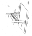
- FIG. 1 depicts a perspective view of an embodiment of a robotic gantry system 100, according to an embodiment of the present disclosure.
- the gantry system 100 shown in FIG. 1 has three major structural members: two columns 102(1)-102(2) that each ride on a rail 103(1)-103(2), and a bridge 104 that connects the columns 102(1)-102(2).
- the bridge 104 by its design is relatively lightweight for the stiffness it affords, as described in further detail as follows.
- the gantry system is configured and arranged for moving a fluid delivery assembly (e.g., nozzle) in three-dimensional space (volume) defined by an X axis in the direction of the rails 103(1)-103(2), a Yin the direction of the bridge 104, and a Z axis in the vertical direction.
- a fluid delivery assembly e.g., nozzle
- the two columns 102(1)-102(2) are each supported by two cables that restrict the possible deflection of the columns in the X axis upon highly accelerated/decelerated motion or rapid change of direction along this axis.
- the main support for the cables are the two square (blue) structures 101(1)-101(2) on each end of the bridge.
- the triangular structure 112 in the middle of the bridge transfers the cable tensile forces to the bridge thereby adding significantly to its stability.
- the gantry system 100 has three degrees of freedom: in direction of X, along the rails 103(1)-103(2); in direction of Y, along the bridge 104; and, in direction of Z, along the two vertical columns 102(1)-102(2).
- the gantry system can place a fluid delivery nozzle (not shown) at a desired location in a volume of space for constructing a structure.
- Contour Crafting techniques and/or nozzles as described in U.S. Patent No. 7,153,454 , noted previously may be used.
- a special feature of gantry system 100 is that it does not explicitly have a Z axis.
- the movement in the vertical direction is achieved by the elevation and lowering of the entire bridge 104.
- This arrangement has several advantages, most notably it has the added stiffness that would be difficult to achieve using prior art designs, e.g., a commonly used vertical mast that rides on the bridge, moving the nozzle along its length.
- the movement is the X direction can be provided by two servo motors 105(1)-105(2), each exerting linear force through a suitable arrangement, e.g., a rack and pinion arrangement.
- Each motor 105(1)-105(2) is vertically mounted at the base of each vertical column 102(1)-102(2), which ride on either groove or linear bearings or other sliding mechanisms.
- Two bearings 108(1)-108(2) that run inside the U channel under the rail, e.g., 103(1) prevent the columns 102(1)-102(2) from being lifted, which could otherwise happen when sudden change of direction or start and stop take pace.
- the two motors 105(1)-105(2) can be synchronized through a master-slave protocol implemented by a main controller.
- the slave motor can be moved each time by the magnitude generated as feed back by the encoder signal of the master motor.
- the X motors 105(1)-105(2) can be equipped with electro-mechanical brakes (not shown) that can be automatically activated when power is disconnected. Hence the X motors 105(1)-105(2) can be prevented from accidentally being moved out of their parked location by an external force.
- FIG. 3 movement along the Y direction is made possible by means of a timing belt mechanism that is driven by a third servo motor (114(1) in Fig. 3 behind the square structure 101(1).
- the motor (114(1) can utilize a right-angle (90 degree shaft conversion) gearhead.
- the belt drives the cart 150 that holds the nozzle assembly (not shown) under the bridge 104.
- a counter-mass 152 can be attached to the upper part of the timing belt.
- the counter-mass 152 can ride on top of the bridge 104 and always moves in the opposite direction if the cart assembly 150. This arrangement prevents side forces that could deflect the entire structure in the direction of the Y axis upon sudden motions or change of directions. Using this arrangement the columns 102(1)-102(2) do not need to be stiffened in the Y direction. This reduces the overall width of the machine 100.
- Movement along Z direction is provided by the motor shown 140 in FIG. 4 .
- This motor 140 which may also be equipped with a right-angle gearhead, can drive two cable spools (shown as 142 in FIGS. 4 and 5 ).
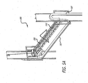
- FIG. 5A depicts another perspective view of the bridge and columns of FIG. 1 .
- the two spools 142 can be connected by way of a long rod, therefore turning one spool would simultaneously turn the other.
- the spools wind and pull on cables that are secured to the top of each vertical column. This action results in elevation f the bridge assembly. Reverse rotation of the spools lowers the assembly.
- the driving motor may be equipped with an electro-mechanical brake which activates when electricity is cut off from the motor.
- An alternative approach would be the use of a worm gear for the Z motor. So-called worm gears cannot be back-driven, hence in the event of power loss the gear inherently prevents the movement of the bridge assembly.
- both rack and pinion sets can be used instead of the cable approach shown in FIG. 5A , one on each vertical Z axis column.
- both pinions may be driven by the same shaft driven by a single servo motor.
- the pinion of each set may be driven by a servo motor.
- the two servo motors would be synchronized in the like manner as in the X axis explained earlier (i.e., a master/slave configuration).
- FIG. 5B shows an alternate embodiment 500 for connecting the bridge to the columns.
- one difficulty with making gantry system of FIG. 1 deployable for use on construction sites is the alignment problem. If the distance between the rails is not equal to the length of the Y bridge then the misalignment could impede and jam the up and down movement of the Y bridge.
- one end of the Y bridge 520 may be connected by means of a hinge 524 to its corresponding vertical slide mechanism 522, as shown in FIG. 5B .
- FIGS. 6 through 9 demonstrates the functions of each set of cables used in the particular embodiment 100 shown in FIG. 1 .
- each set of cable is described incrementally.
- FIG. 6 depicts a perspective view of the robotic gantry system of FIG.1 with only two cables 120(1)-120(2) providing resistance against bending in the X direction shown.
- the set of cables shown in FIG. 6 provide stiffness in the direction of the X axis. Any deflection of the main horizontal member (the gantry bridge) would necessitate the stretching of the cables shown. Resistance of the cables 120(1)-120(2) would therefore add significantly to the stiffness of the gantry bridge. Stiffness of the gantry bridge is crucial especially during acceleration and decelerations in the X axis direction (such as at the beginning and ending of walls).
- FIG. 7 depicts a perspective view of the robotic gantry system of FIG.1 with cables providing resistance against rotation of the gantry bridge due to the inertia of the metering devices and nozzle assembly that is mounted under the bridge, in addition to those cables shown in FIG. 6 .
- the cable arrangement shown in FIG. 7 including cables 122(1)-122(2), is used to provide stiffness against rotation of the gantry bridge 104 due to the inertia of the metering devices and nozzle assembly that is mounted under the bridge.
- the imbalance of the mass on top and bottom of the bridge would result in forces that tend to rotate the bridge upon acceleration and deceleration along the X axis.
- the triangular structure 112 in the middle of the bridge transfers the cable tensile forces to the bridge thereby adding significantly to its stability.
- FIG. 8 depicts a perspective view of the robotic gantry system of FIG. 1 with cables that prevent the bridge from bending in the vertical direction, in addition to those cables shown in FIGS. 6-7 .
- the cable arrangement shown in FIG. 8 including cables 124(1)-124(4), serve to prevent the bridge from bending in the vertical direction. Note that the cables facing each other from opposite directions along the length of the bridge overlap over a segment of the bridge. If this overlap does not exist the bridge could still bend along the segment between the two ends of the cable that are connected to the middle region of the bridge.
- FIG. 9 depicts cables that compensate for all the tensile forces of the cables in FIGS. 6-8 above the bridge, in addition to those cables shown in FIG. 6-8 .
- cables 126(1)-126(2) compensate for all the tensile forces of the aforementioned cables (shown in FIGS. 6-8 ) above the bridge 102. There are two such cables 126(1)-126(2), one on each side of the bridge.
- the gantry system provides only three directions of motion to the fluid delivery nozzle. Rotation motion is preferable, however, for the fluid delivery nozzle to build various geometrical features (such as corners, curves, etc.). Given that cementitious materials used by fluid delivery often require fairly rigid and thick hoses that are hard to wind around the nozzle upon rotation, a mechanism is preferably used that will not need excessive rotation forces and can operate in a relatively small volume.
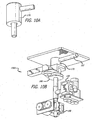
- FIGS. 10A-10B depict, respectively, perspective views of a nozzle assembly used with a rotary union and metering devices, in accordance with a further embodiment of the present disclosure.
- a rotary union 170 such as shown in FIGS. 10A-10B , may be used for such a purpose.
- a rotary union can receive a fluid in its inlet and direct it through a pipe that can be rotated by an indefinite number of degrees.
- a Deublin Rotary Union made available by Deublin Company, 2050 Norman Drive West, Waukegan, IL 60085 , USA.
- FIGS. 10A, FIG. 10B , and FIG. 11 show how a rotary union 170 may be attached to the gantry cart/platform and its output pipe rotated by a servo motor 180.
- the output pipe of the rotary union may be attached to metering devices 190 that feed into the fluid delivery nozzle (nozzle 153 in FIG. 11 ).
- two metering devices190 are used, one for the outside orifices of the fluid delivery nozzle and another for its internal orifice.
- a different number of metering devices may be used; moreover, any suitable metering device may be used.
- Exemplary embodiments can utilize metering and pumping devices 190 as described in U.S. Patent Application Serial Number 11/-,-, entitled “Metering and Pumping Devices,” filed November 2, 2007, attorney docket no. 28080-289, which claims priority to of U.S. Provisional Application Serial No. 60/864,060 , entitled “Metering and Pumping Devices," Attorney Docket No. 28080-251, filed November 2, 2006 and U.S. Provisional Application Serial No. 60/864,291 , entitled “Metering and Pumping Devices," Attorney Docket No. 28080-252, filed November 3, 2006.
- the material hose 107 may be directed through the same cable tracks that connect the motors and sensors (such as end of limit switches).
- a single material hose 107 may be connected to the inlet of the rotary union170 mounted on the nozzle assembly cart/platform 150. The single flow may then be divided into two, each entering a metering device the outlets of which are connected to the inlets of the fluid delivery nozzle.
- FIG. 12 depicts a gantry system 1200, similar to system 100 of FIG. 1 , with a robotic manipulator and separate moveable tray useful for installing building components to a structure being built.
- a robotic manipulator 1210 may be installed on a gantry bridge 1202 that could move on the bridge 1202 jointly with or independently of a nozzle assembly 1220.
- the manipulator 1210 may be used for placing reinforcement, plumbing, electrical or other modules 1240 inside the structure as it is constructed.
- a tray 1250 may be used as a source of the modules and may be placed at one end of the gantry work envelope, as shown.
- Such a tray 1250 may be elevated by its own independent motorized system each time the gantry bridge 1202 is elevated such that the tray 1250 always stays at an elevation that would make the modules 1240 accessible to the robotic manipulator 1210.
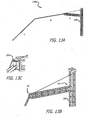
- FIGS. 13A-13C depict an alternative embodiment 1300 for routing the material hose 107 (not shown) through cable tracks is an independent routing approach by means of a passive articulated arm.
- the advantage of this method/embodiment is reduction in the hose length and the possibility of using larger diameter hoses, which would be problematic to route through cable carriers (because of large diameter and large radius of bend).
- the articulated arm A-C could be mounted on an adjacent wall or on its own independent vertical truss 200 which could be installed at a corner of the work envelope of the robot (e.g., the North-East corner).
- the arm may have a desired number of segments, e.g., three segments (A+B+C), that are hinged together. These segments can collectively direct the hose from the material source to the nozzle on the robotic gantry system, e.g., system 100 of FIG. 1 .
- Segment A is hinged at H1 to the vertical post 200 (in FIG. 12C ) and can swing in a horizontal plane.
- This segment can be made of a truss to resist bending as well as torsion forces exerted by Segment B.
- a cable may be used 220.
- segment B attached to the end of segment A is segment B which also swings in the horizontal plane only around the hinge shown as H2.
- the end of segment B is attached by means of a universal joint (which allows swinging sideways as well as up and down) to segment C.
- the articulated arm moves passively by the force of the robot, however, the major portion of the weight of the material hose is carried by segments A and B of the arm.
- the only weight exerted on the robot e.g., system 100 of FIG. 1
- the material hose is not drawn in the FIGS. 13A-13C .
- An exemplary aspect may relate to robotic gantry system comprising:
- the nozzle assembly comprises a nozzle connected to a nozzle platform.
- the first plurality of cables includes two cables providing resistance against bending in the horizontal X direction;
- the plurality of cables includes two or more cables providing resistance against rotation of the gantry bridge due to the inertia of the nozzle platform mounted to the bridge;
- the plurality of cables includes two or more cables that prevent the bridge from bending in the horizontal Y direction.
- the plurality of cables include a second plurality of cables configured and arranged to compensate for the tensile forces of the first plurality of cables.
- the position controller comprises a position sensor configured to sense the position of the nozzle assembly with respect to one or more reference locations.
- the robotic gantry system includes a counter weight coupled to a timing belt coupled to the nozzle platform, wherein the wording "counter weight” is a synonym for the wording "counter-mass”.
- the position sensor comprises a laser rangefinder, the laser rangefinder including: a transmitter configured to generate laser light and transmit the laser light to one or more reflectors positioned at a respective one of the one or more reference locations; a receiver configured to receive laser light generated by the transmitter and back-scattered from the reflectors, and a photodetector configured to detect the intensity of the received light; and a processor configured to determine the position of the nozzle assembly by measuring the time required for the laser light to travel to and from each of the retroref lector s.
- the laser rangefinder including: a transmitter configured to generate laser light and transmit the laser light to one or more reflectors positioned at a respective one of the one or more reference locations; a receiver configured to receive laser light generated by the transmitter and back-scattered from the reflectors, and a photodetector configured to detect the intensity of the received light; and a processor configured to determine the position of the nozzle assembly by measuring the time required for the laser light to travel to and from each of the retroref lector
- the robotic gantry system includes a material feed system configured to feed material to the nozzle, wherein the material feed system includes a container configured to store material, and a fluid delivery tube configured to deliver material stored in the container to the nozzle.
- the robotic gantry system includes a robotic manipulator connected to the bridge and configured and arranged to install building components on a structure being built.
- the robotic gantry system includes a movable tray configured and arranged to be at an elevation accessible to the robotic manipulator.
- the robotic gantry system includes the nozzle assembly comprises a multi-nozzle assembly including: a first nozzle configured to extrude material through a first outlet; a second nozzle configured to extrude material through a second outlet; a third nozzle configured to extrude material through a third outlet, the third outlet being between the first and second outlets; and a first and second trowel configured to shape material extruded from the first and second nozzles, respectively.
- the multi-nozzle assembly further includes a nozzle position controller configured to controllably vary the height of at least one of the outlets with respect to the height of at least one of the other outlets.
- the robotic gantry system includes one or more metering devices configured and arranged to meter a supply of fluid to the nozzle assembly.
- the material feed system comprises a passive articulated arm configured and arranged to support a fluid delivery hose.
- the passive articulated arm comprises a vertical truss.
- the vertical truss further comprises a cantilever with a distal end and a proximal end that is connected to the vertical truss by a hinge.
- An further aspect may relate to a construction apparatus, comprising:
- the nozzle assembly includes a nozzle configured to extrude material through an outlet, and a trowel configured to shape material extruded from the nozzle.
- the lifting mechanism is configured to exert force on the cables so as to cause the plurality of cables to collectively hoist the gantry platform to a desired height.
- the movable gantry platform comprises a plurality of cross-members, each of the cross-members extending between, and slidably mounted across, the pair of opposite side-members; and wherein the movable gantry platform further comprises a plurality of nozzle assemblies, each of the nozzle assemblies movably coupled to a respective one of the cross-members.
- the construction apparatus includes one or more attachment members extending from points along the gantry platform and configured to anchor the gantry platform to a rigid structure, each of the attachment members having a wheel affixed thereto, the wheel configured to be in contact with the rigid structure.
- the nozzle assembly comprises a multi-nozzle assembly including:
- An further aspect may relate to a mobile robotic system, comprising:
- Another aspect may relate to a robotic gantry system comprising:
- the robotic gantry system may include two cables providing resistance against bending of the bridge in the horizontal X direction.
- the robotic gantry system may include two or more cables providing resistance against rotation of the bridge due to the inertia of the nozzle platform mounted to the bridge.
- the robotic gantry system may include two or more cables that prevent the bridge from bending in the horizontal Y direction.
- the robotic gantry system may include a plurality of cables configured and arranged to compensate for tensile forces.
- the robotic gantry system may include a counter weight coupled to a timing belt coupled to a nozzle assembly.
- Another aspect may relate to another robotic gantry system including first and second columns each slidably riding a substantially horizontal rail; a bridge slidably connected to the first and second columns so as to permit silding of the bridge vertically with respect to the columns; a cable support arm affixed to and extending upwardly from approximately the center of the bridge; at least one cable connected between each cable support arm at a location above an end of the bridge and to the anchor arm at a location above the approximate center of the bridge, the cable being configured to cooperate with the anchor arm to substantially prevent twisting of the bridge; and a nozzle assembly slidably connected to the bridge and configured to extrude cementitious material.
- the at least one cable includes two cables attached to each cable support arm at two locations on the cable support arm that are horizontally spaced-apart from one another.
- the two cables cross at the approximate location at which they attach to the anchor arm.
- another robotic gantry system may include
- Exemplary the robotic gantry system may further include a timing belt coupled to the counter-mass and to the nozzle assembly .
- Another aspect may relate to a further robotic gantry system including first and second columns each slidably riding a substantially horizontal rail; a bridge slidably connected to the first and second columns so as to permit silding of the bridge vertically with respect to the columns; a cable support arm extending upwardly from each end of the bridge; at least one cable connected to the bridge and configured to extrude cementitious material.
- the cables cross one another.
- the cables cross one another at a point approximately at the center of the bridge.
Landscapes
- Engineering & Computer Science (AREA)
- Mechanical Engineering (AREA)
- Robotics (AREA)
- Manipulator (AREA)
- Spray Control Apparatus (AREA)
- Golf Clubs (AREA)
- Non-Portable Lighting Devices Or Systems Thereof (AREA)
Claims (15)
- Système de portique robotique (100) comprenant :des première et seconde colonnes (102) se déplaçant chacune sur un rail (103) ;un pont (104) connectant les première et seconde colonnes (102), le pont (104) incluant un ou plusieurs câbles configurés et agencés pour résister à la flexion du pont (104) ;un ensemble de tuyères connecté à coulissement au pont (104) ; etun contrepoids (152) qui peut se déplacer sur le pont (104) et se déplace toujours dans la direction opposée de l'ensemble de tuyères.
- Système de portique robotique (100) selon la revendication 1, comprenant en outre :- une première pluralité de câbles (120) fournissant aux colonnes (102) et au pont (104) une résistance à la flexion ; et/ou comprenant en outre- une pluralité de moteurs (105) configurés et agencés pour déplacer les première et seconde colonnes (102) en tant que module, le pont (104) et/ou une plate-forme (150), et dans lequel la pluralité de moteurs (105) sont configurés et agencés pour déplacer l'ensemble de tuyères dans une direction horizontale X, une direction horizontale Y et une direction verticale Z, dans lequel la plate-forme (150) peut être située en un emplacement souhaité avec un volume ; et/ou comprenant en outre- un contrôleur de mouvement configuré et agencé pour commander le mouvement et la position de l'ensemble de tuyères dans le volume.
- Système de portique robotique (100) selon la revendication 1 ou 2, dans lequel chacune des première et seconde colonnes (102) se déplace à coulissement sur un rail essentiellement horizontal (103), dans lequel le pont (104) est connecté à coulissement aux première et seconde colonnes (102) de manière à permettre le coulissement du pont (104) verticalement par rapport aux colonnes (102), et dans lequel l'ensemble de tuyères est configuré pour extruder du matériau cimentaire.
- Système de portique robotique (100) selon l'une quelconque des revendications 1 à 3, dans lequel
le contrepoids (152) est configuré pour se déplacer horizontalement sur le pont (104) toujours dans la direction opposée de l'ensemble de tuyères de manière à minimiser la génération de forces latérales suite au mouvement de l'ensemble de tuyères. - Système de portique robotique (100) selon l'une quelconque des revendications 1 à 4, comprenant en outre une courroie de distribution raccordée au contrepoids (152) et à l'ensemble de tuyères.
- Système de portique robotique (100) selon la revendication 5, dans lequel la courroie de distribution entraîne un chariot (150) et maintient l'ensemble de tuyères sous le pont (104), et dans lequel
le contrepoids (152) peut se déplacer au-dessus du pont (104) et se déplace toujours dans les directions opposées du chariot (150). - Système de portique robotique (100) selon la revendication 6, dans lequel le contrepoids (152) peut être relié à la partie supérieure de la courroie de distribution afin de neutraliser ou mitiger les effets de la quantité de mouvement de la masse de l'ensemble de chariot (150).
- Système de portique robotique (100) selon la revendication 7, dans lequel le contrepoids (152) est agencé de manière à empêcher des forces latérales qui pourraient dévier la structure entière dans la direction de l'axe Y suite à des mouvements soudains ou un changement de directions.
- Système de portique robotique (100) selon la revendication 1, dans lequel :le pont (104) étant relié à une extrémité à une des colonnes (102) avec une charnière qui est configurée pour permettre au pont (104) de tourner dans un plan vertical par rapport à la colonne (102) à laquelle le pont (104) est relié de manière articulée de manière à empêcher un blocage en cas de mauvais alignement, et le pont étant connecté à l'autre extrémité à l'autre colonne par des mécanismes de palier au moins en deux points avec une certaine distance verticale, les deux extrémités du pont étant suspendues par des câbles ou étant engagées avec les colonnes par une crémaillère et des pignons.
- Système de portique robotique (100) selon la revendication 9, incluant deux câbles fournissant une résistance contre la flexion du pont (104) dans la direction horizontale X et/ou incluant deux câbles ou plus fournissant une résistance contre la rotation du pont (104) en raison de l'inertie de la plate-forme de tuyères montée sur le pont (104) et/ou incluant deux câbles ou plus qui empêchent le pont (104) de fléchir dans la direction horizontale Y et/ou incluant une pluralité de câbles configurés et agencés pour compenser des résistances à la traction.
- Système de portique robotique (100) selon la revendication 9, comprenant en outre un contrepoids raccordé à une courroie de distribution raccordée à l'ensemble de tuyères et/ou l'autre extrémité du pont (104) n'est pas reliée à l'autre colonne (102) avec une charnière.
- Système de portique robotique (100) selon la revendication 1, comprenant en outre :un bras de support de câble s'étendant vers le haut depuis chaque extrémité du pont (104) ;un bras d'ancrage fixé à et s'étendant vers le haut depuis approximativement le centre du pont (104) ; etau moins un câble connecté entre chaque bras de support de câble en un emplacement au-dessus d'une extrémité du pont (104) et au bras d'ancrage en un emplacement au-dessus du centre approximatif du pont (104), le câble étant configuré pour coopérer avec le bras d'ancrage afin d'essentiellement empêcher la torsion du pont (104).
- Système de portique robotique (100) selon la revendication 10, dans lequel au moins un câble inclut deux câbles reliés à chaque bras de support de câble en deux emplacements sur le bras de support de câble qui sont horizontalement espacés l'un de l'autre et/ou dans lequel deux câbles se croisent à l'emplacement approximatif auquel ils sont reliés au bras d' ancrage.
- Système de portique robotique (100) selon la revendication 1, comprenant en outre :un bras de support de câble s'étendant vers le haut depuis chaque extrémité du pont (104) ; etau moins un câble connecté à une extrémité entre chaque bras de support de câble en un emplacement au-dessus d'une extrémité du pont (104) et à l'autre extrémité au pont (104) en un emplacement entre les deux extrémités du pont (104).
- Système de portique robotique (100) selon la revendication 14, dans lequel les câbles se croisent l'un l'autre et/ou dans lequel les câbles se croisent l'un l'autre en un point approximativement au centre du pont (104).
Applications Claiming Priority (3)
| Application Number | Priority Date | Filing Date | Title |
|---|---|---|---|
| US86429306P | 2006-11-03 | 2006-11-03 | |
| US11/934,507 US8029710B2 (en) | 2006-11-03 | 2007-11-02 | Gantry robotics system and related material transport for contour crafting |
| EP07844870A EP2079656B1 (fr) | 2006-11-03 | 2007-11-05 | Système de portique robotique |
Related Parent Applications (1)
| Application Number | Title | Priority Date | Filing Date |
|---|---|---|---|
| EP07844870.1 Division | 2007-11-05 |
Publications (2)
| Publication Number | Publication Date |
|---|---|
| EP2324971A1 EP2324971A1 (fr) | 2011-05-25 |
| EP2324971B1 true EP2324971B1 (fr) | 2012-05-23 |
Family
ID=39365290
Family Applications (2)
| Application Number | Title | Priority Date | Filing Date |
|---|---|---|---|
| EP07844870A Not-in-force EP2079656B1 (fr) | 2006-11-03 | 2007-11-05 | Système de portique robotique |
| EP10015728A Not-in-force EP2324971B1 (fr) | 2006-11-03 | 2007-11-05 | Système de portique robotique avec un contrepoids |
Family Applications Before (1)
| Application Number | Title | Priority Date | Filing Date |
|---|---|---|---|
| EP07844870A Not-in-force EP2079656B1 (fr) | 2006-11-03 | 2007-11-05 | Système de portique robotique |
Country Status (7)
| Country | Link |
|---|---|
| US (1) | US8029710B2 (fr) |
| EP (2) | EP2079656B1 (fr) |
| AT (1) | ATE512927T1 (fr) |
| CA (1) | CA2667483C (fr) |
| HK (1) | HK1136810A1 (fr) |
| MX (1) | MX2009004608A (fr) |
| WO (1) | WO2008058077A2 (fr) |
Families Citing this family (69)
| Publication number | Priority date | Publication date | Assignee | Title |
|---|---|---|---|---|
| US8801415B2 (en) | 2005-01-21 | 2014-08-12 | University Of Southern California | Contour crafting extrusion nozzles |
| IT1392130B1 (it) * | 2008-11-03 | 2012-02-22 | Eden Technology Srl | Dispositivo di sterzatura automatica per carrelli semoventi di sollevamento e trasporto manufatti. |
| US8863773B2 (en) * | 2008-11-10 | 2014-10-21 | University Of Southern California | Fluid metering device using free-moving piston |
| MX2011010551A (es) * | 2009-04-15 | 2011-10-19 | Vsl Int Ag | Carro de puente grua colgante y metodo. |
| CN102166750B (zh) * | 2011-05-16 | 2014-01-29 | 机械科学研究总院先进制造技术研究中心 | 定位梁及具有该定位梁的机器人直线运动单元 |
| US8434657B2 (en) | 2011-06-09 | 2013-05-07 | Landoll Corporation | Gantry-based welding system and method |
| US8210418B1 (en) | 2011-06-09 | 2012-07-03 | Landoll Corporation | Multi-station, gantry-based automated welding system |
| CN103128946B (zh) * | 2012-11-30 | 2015-05-27 | 广州市华南橡胶轮胎有限公司 | 一种移动式橡胶挤出设备 |
| CN103266779B (zh) * | 2013-05-23 | 2016-03-30 | 广州建筑股份有限公司 | 一种越过水平障碍物的提升滑移施工设备及其方法 |
| US20140363532A1 (en) * | 2013-06-10 | 2014-12-11 | Kirk W. Wolfgram | Multiple color extrusion type three dimensional printer |
| CA2919373C (fr) * | 2013-07-29 | 2021-09-21 | Richard J. Mccaffrey | Coulee robotisee portative d'elements de construction modulaires volumetriques |
| US20150176750A1 (en) * | 2013-12-20 | 2015-06-25 | The Procter & Gamble Company | Base for a flexible mount converter |
| EP3131720A4 (fr) | 2014-04-16 | 2017-09-13 | University Of Southern California | Construction automatisée de tours et de colonnes |
| US10102585B1 (en) | 2014-04-25 | 2018-10-16 | State Farm Mutual Automobile Insurance Company | Systems and methods for automatically mitigating risk of property damage |
| US10118714B2 (en) | 2014-04-30 | 2018-11-06 | The Boeing Company | System and method for positioning an automated assembly tool relative to a structure |
| US9776330B2 (en) | 2014-04-30 | 2017-10-03 | The Boeing Company | Crawler robot and supporting platform |
| US10000298B2 (en) | 2014-04-30 | 2018-06-19 | The Boeing Company | Metrology system for positioning assemblies |
| US9486917B2 (en) | 2014-04-30 | 2016-11-08 | The Boeing Company | Mobile automated assembly tool for aircraft structures |
| US10427254B2 (en) | 2014-04-30 | 2019-10-01 | The Boeing Company | Flexible manufacturing for aircraft structures |
| US9708079B2 (en) * | 2014-04-30 | 2017-07-18 | The Boeing Company | Mobile automated overhead assembly tool for aircraft structures |
| US10017277B2 (en) | 2014-04-30 | 2018-07-10 | The Boeing Company | Apparatus, system, and method for supporting a wing assembly |
| US9579679B2 (en) * | 2014-05-28 | 2017-02-28 | The Boeing Company | Aircraft coating application system and method |
| US9856037B2 (en) * | 2014-06-18 | 2018-01-02 | The Boeing Company | Stabilization of an end of an extended-reach apparatus in a limited-access space |
| US10356303B1 (en) | 2014-10-07 | 2019-07-16 | State Farm Mutual Automobile Insurance Company | Systems and methods for controlling smart devices based upon image data from image sensors |
| JP6402684B2 (ja) * | 2015-06-10 | 2018-10-10 | トヨタ自動車株式会社 | 表示装置 |
| CN105035745A (zh) * | 2015-07-31 | 2015-11-11 | 苏州速腾电子科技有限公司 | 一种搬运装置 |
| US20170167148A1 (en) * | 2015-12-10 | 2017-06-15 | Caterpillar Inc. | Construction system |
| HUP1600186A2 (en) | 2016-03-08 | 2017-09-28 | Cnc-Instruments Bt | Device and method for constructing buildings by 3d printing |
| US9919510B2 (en) | 2016-04-12 | 2018-03-20 | Massachusetts Institute Of Technology | Methods and apparatus for additive manufacturing with molten glass |
| BR112019000722B1 (pt) | 2016-07-15 | 2023-03-28 | Fastbrick Ip Pty Ltd | Lança extensível telescópica para transportar item e lança dobrável |
| CN109790723B (zh) | 2016-07-15 | 2021-12-31 | 快砖知识产权私人有限公司 | 结合在交通工具中的砖块/砌块铺设机器 |
| WO2018009978A1 (fr) * | 2016-07-15 | 2018-01-18 | Fastbrick Ip Pty Ltd | Applicateur d'adhésif et tête de placement d'objet l'incorporant |
| AT518899B1 (de) | 2016-08-05 | 2018-02-15 | Metallconcept Gmbh | Vorrichtung zur Herstellung wenigstens eines dreidimensionalen Schichtkörpers für die Bauindustrie |
| US11273574B2 (en) | 2016-08-29 | 2022-03-15 | United States Of America As Represented By The Secretary Of The Army | Scalable three dimensional printing apparatus |
| CN106315413B (zh) * | 2016-08-29 | 2017-11-07 | 宁夏巨能机器人股份有限公司 | 一种龙门桁架机器人的控制系统及其控制方法 |
| CN106181981B (zh) * | 2016-09-28 | 2018-06-05 | 天津工业大学 | 一种用于相机扫描钢板进行测量的三维机械臂结构 |
| US10307959B2 (en) * | 2016-09-29 | 2019-06-04 | The United States Of America As Represented By The Secretary Of The Army | Concrete delivery system |
| CN106872157B (zh) * | 2016-12-19 | 2019-10-25 | 天津工业大学 | 一种重型机床结构件装配应力测试试验平台 |
| US10061323B2 (en) | 2016-12-22 | 2018-08-28 | Advanced Construction Robotics, Inc. | Autonomous apparatus and system for repetitive tasks in construction project |
| US10675769B2 (en) | 2017-01-27 | 2020-06-09 | The Boeing Company | Cable carrier crossover supplying four non-static locations |
| US10344906B2 (en) | 2017-01-27 | 2019-07-09 | The Boeing Company | Isolated human work platform for stabilized positioning of collaborative robotics |
| US10815679B2 (en) | 2017-01-27 | 2020-10-27 | The Boeing Company | System for four collaborative robots and humans in a narrowing work envelope |
| US10745251B2 (en) * | 2017-01-27 | 2020-08-18 | The Boeing Company | Belt drive dual robot gantry |
| RU177441U1 (ru) * | 2017-04-04 | 2018-02-21 | федеральное государственное бюджетное образовательное учреждение высшего образования "Белгородский государственный технологический университет им. В.Г. Шухова" | Строительный робот |
| CN207189642U (zh) * | 2017-05-18 | 2018-04-06 | 北京华沁智联科技有限公司 | 导轨 |
| US10920434B1 (en) | 2017-06-23 | 2021-02-16 | Kent Douglas Pearson, Jr. | Portable robotic construction system |
| EP3649616A4 (fr) | 2017-07-05 | 2021-04-07 | Fastbrick IP Pty Ltd | Dispositif de suivi de position et d'orientation en temps réel |
| EP3668689A4 (fr) | 2017-08-17 | 2021-04-28 | Fastbrick IP Pty Ltd | Configuration de système d'interaction |
| CN111226090B (zh) | 2017-08-17 | 2023-05-23 | 快砖知识产权私人有限公司 | 具有改进的横滚角测量的激光跟踪器 |
| CN111212799B (zh) | 2017-10-11 | 2023-04-14 | 快砖知识产权私人有限公司 | 用于传送物体的机器以及与其一起使用的多隔间转盘 |
| ES2726921B2 (es) * | 2018-04-10 | 2020-05-25 | Evolution Construction System S L | Sistema de construccion robotizado. |
| SI25656A (sl) | 2018-06-01 | 2019-12-31 | Jože Abram | Mešalno brizgalna glava za tridimenzionalni tiskalnik za tiskanje sten zgradb in metoda tiskanja |
| RU188945U1 (ru) * | 2018-07-13 | 2019-04-30 | федеральное государственное бюджетное образовательное учреждение высшего образования "Белгородский государственный технологический университет им. В.Г. Шухова" | Портальный манипулятор для получения крупногабаритных изделий методом аддитивной печати |
| US10782696B2 (en) | 2018-09-07 | 2020-09-22 | The Boeing Company | Mobile fixture apparatuses and methods |
| US11072439B2 (en) | 2018-09-07 | 2021-07-27 | The Boeing Company | Mobile fixture apparatuses and methods |
| US10472095B1 (en) | 2018-09-07 | 2019-11-12 | The Boeing Company | Mobile fixture apparatuses and methods |
| WO2020065375A1 (fr) | 2018-09-26 | 2020-04-02 | Trawi 3D Constructions S.A.R.L. | Appareil d'impression en trois dimensions |
| US11124961B2 (en) | 2018-11-13 | 2021-09-21 | Stratasys, Inc. | System and method for 3D construction printing |
| US10597264B1 (en) | 2018-12-20 | 2020-03-24 | Advanced Construction Robotics, Inc. | Semi-autonomous system for carrying and placing elongate objects |
| US11408166B2 (en) * | 2018-12-21 | 2022-08-09 | Icon Technology, Inc. | Systems and methods for the construction of structures utilizing additive manufacturing techniques |
| EP3898144A4 (fr) * | 2018-12-21 | 2022-07-27 | Icon Technology, Inc. | Systèmes et procédés pour la construction de structures utilisant des techniques de fabrication additive |
| EP3927915A1 (fr) | 2019-02-19 | 2021-12-29 | Basf Se | Procédé de fabrication additive pour la fabrication de segments contenant du béton d'un objet tridimensionnel |
| DE102019109019A1 (de) | 2019-04-05 | 2020-10-08 | Liebherr-Werk Biberach Gmbh | Bau- und/oder Materialumschlagsmaschine sowie Verfahren zum Führen und Bewegen eines Arbeitskopfs |
| CZ2019387A3 (cs) * | 2019-06-19 | 2020-02-26 | ÄŚeskĂ© vysokĂ© uÄŤenĂ technickĂ© v Praze | Zařízení pro změnu dynamické tuhosti portálové nebo letmo uložené konstrukce |
| CN110342243A (zh) * | 2019-06-23 | 2019-10-18 | 北京鲲鹏神通科技有限公司 | 一种无人化智能厨房取料机械手 |
| EP3771539B1 (fr) * | 2019-08-01 | 2023-04-19 | Fundación Tecnalia Research & Innovation | Têtes d'impression pour l'impression avec un matériau cimentaire |
| IT202000030872A1 (it) * | 2020-12-15 | 2022-06-15 | Faspar S P A | Gruppo di supporto e movimentazione per un dispositivo di presa per utensili |
| US11708937B2 (en) * | 2021-03-04 | 2023-07-25 | Caterpillar Inc. | Method and apparatus for gantry system mobility |
| FI129894B (fi) * | 2021-05-21 | 2022-10-31 | Cimcorp Oy | Varaston väliseinä |
Family Cites Families (51)
| Publication number | Priority date | Publication date | Assignee | Title |
|---|---|---|---|---|
| US634026A (en) * | 1899-05-29 | 1899-10-03 | William H H Pittman | Trussed suspension-bridge. |
| US984517A (en) * | 1910-02-28 | 1911-02-14 | Rudolph Rollinger | Outside wall. |
| US1578511A (en) * | 1923-02-08 | 1926-03-30 | Frederic E Gladwin | Wall construction |
| US2556503A (en) * | 1947-09-22 | 1951-06-12 | George T Nelson | Automatically steered carriage for road paving machines |
| GB781465A (en) | 1954-03-29 | 1957-08-21 | Cyril Walter Kenward | Improvements in or relating to positioning, assembling or manipulating apparatus |
| US3221456A (en) * | 1960-05-27 | 1965-12-07 | Dor Seal Ltd | Pane support and seal |
| SE319892B (fr) * | 1968-06-17 | 1970-01-26 | N Larsson | |
| US3562991A (en) * | 1968-07-29 | 1971-02-16 | Paul W Kustusch | Building wall construction and module therefor |
| US3826196A (en) * | 1969-10-08 | 1974-07-30 | Wallace Prod Corp B | Load-handling gantries |
| US3909863A (en) * | 1972-09-11 | 1975-10-07 | Krupp Gmbh | Bridge crane girder |
| GB1446853A (en) * | 1972-12-08 | 1976-08-18 | Dobie C H | Gantry cranes |
| US3966533A (en) * | 1973-04-19 | 1976-06-29 | Goldsworthy Engineering, Inc. | On-site wall structure formation |
| US3957137A (en) * | 1974-03-12 | 1976-05-18 | Vermette Howard H | Portable material lift |
| US4040105A (en) | 1975-09-23 | 1977-08-02 | International Business Machines Corporation | Magnetic disk drive unit with flexible skirt |
| US4051805A (en) | 1975-11-11 | 1977-10-04 | Amchem Products, Inc. | Can washing and coating system |
| US4067446A (en) * | 1976-02-24 | 1978-01-10 | Ray Louis F | Cable stay crane |
| US4066723A (en) * | 1976-03-19 | 1978-01-03 | Caterpillar Tractor Co. | Method and apparatus for making fibrous concrete |
| US4060205A (en) | 1976-11-08 | 1977-11-29 | Allis-Chalmers Corporation | Hydraulic accumulator for use with gyratory crushers and combination of such accumulator with a gyratory crusher |
| US4464803A (en) * | 1982-04-28 | 1984-08-14 | Bonasso S G | Tension arch structure |
| US4475976A (en) * | 1983-12-23 | 1984-10-09 | The Boeing Company | Method and apparatus for forming composite material articles |
| US4658485A (en) * | 1984-08-21 | 1987-04-21 | Yang Tai Her | Machine tool with articulated crossbeam |
| US4637738A (en) * | 1985-07-31 | 1987-01-20 | Vincent Barkley | Alignment compensator for linear bearings |
| US4747745A (en) * | 1985-11-21 | 1988-05-31 | Marathon Letourneau Company | Selective beam gantry crane |
| US4833855A (en) * | 1987-04-27 | 1989-05-30 | Winter Amos G Iv | Prefabricated panel having a joint thereon |
| US4781067A (en) * | 1987-04-30 | 1988-11-01 | Sonoscan, Inc. | Balanced scanning mechanism |
| US5040431A (en) * | 1988-01-22 | 1991-08-20 | Canon Kabushiki Kaisha | Movement guiding mechanism |
| US4850382A (en) * | 1988-09-14 | 1989-07-25 | Barnes Drill Co. | Work booth for a robot |
| GB2233928B (en) * | 1989-05-23 | 1992-12-23 | Brother Ind Ltd | Apparatus and method for forming three-dimensional article |
| ATE131111T1 (de) * | 1991-01-31 | 1995-12-15 | Texas Instruments Inc | Verfahren und vorrichtung zur rechnergesteuerten herstellung von dreidimensionalen gegenständen aus rechnerdaten. |
| US5665382A (en) * | 1993-02-22 | 1997-09-09 | Vivorx Pharmaceuticals, Inc. | Methods for the preparation of pharmaceutically active agents for in vivo delivery |
| US5664382A (en) | 1993-09-09 | 1997-09-09 | Melnick; David W. | Method for making block forms for receiving concrete |
| NL9400124A (nl) * | 1994-01-27 | 1995-09-01 | Buro Eco Home | Bouwwerk en bouwelement daarvoor. |
| US5617515A (en) * | 1994-07-11 | 1997-04-01 | Dynetics, Inc. | Method and apparatus for controlling and programming a robot or other moveable object |
| US5529471A (en) * | 1995-02-03 | 1996-06-25 | University Of Southern California | Additive fabrication apparatus and method |
| DE29615574U1 (de) * | 1996-09-06 | 1998-01-15 | Siemens Ag | Vorrichtung zur temporären Erhöhung der Tragfähigkeit von Brückenträgern |
| US6103161A (en) * | 1997-02-03 | 2000-08-15 | Lopez; Jose Luis Santamaria | Procedure and device for manufacturing plastic extruded sheets |
| US5848458A (en) * | 1997-05-15 | 1998-12-15 | Northrop Grumman Corporation | Reconfigurable gantry tool |
| US6001181A (en) * | 1997-08-01 | 1999-12-14 | Northrop Grumman Corporation | Automated sealant applicator |
| US6170220B1 (en) * | 1998-01-16 | 2001-01-09 | James Daniel Moore, Jr. | Insulated concrete form |
| US6423261B1 (en) * | 1999-02-02 | 2002-07-23 | Daniel R. Joseph | Blown film extrusion apparatus and method with improved collapsing frame |
| US6246203B1 (en) * | 1999-02-05 | 2001-06-12 | Silicon Valley Group, Inc. | Direct skew control and interlock of gantry |
| DE19963948A1 (de) * | 1999-12-31 | 2001-07-26 | Zsolt Herbak | Verfahren zum Modellbau |
| US6662516B2 (en) * | 2001-02-12 | 2003-12-16 | Seismic Rehab, Llc | Reinforced wall structures and methods |
| US20030164200A1 (en) * | 2001-03-16 | 2003-09-04 | American Controls, Inc. | Assembly line fluid filling system and method |
| US6989887B2 (en) * | 2001-06-06 | 2006-01-24 | Nikon Corporation | Dual force mode fine stage apparatus |
| DE10211754B4 (de) | 2002-03-14 | 2004-03-11 | Peter Meyer | Tragrahmenstruktur für ein Hochgeschwindigkeitsbearbeitungsgerät |
| DE10216571A1 (de) | 2002-04-13 | 2003-10-30 | 1 1 Prototyping Herbak Gmbh | Vorrichtung zum Verfahren eines Arbeitskopfes im Raum |
| US7153454B2 (en) * | 2003-01-21 | 2006-12-26 | University Of Southern California | Multi-nozzle assembly for extrusion of wall |
| US7001464B1 (en) * | 2003-03-05 | 2006-02-21 | Erdman Automation Corporation | System and process for glazing glass to windows and door frames |
| US6976599B1 (en) * | 2003-09-26 | 2005-12-20 | The United States Of America As Represented By The Secretary Of The Navy | Multi-rail dual hoisting crane |
| DE102004047525A1 (de) | 2004-09-28 | 2006-04-06 | Dynexa Gmbh | Tragrahmenanordnung, insbesondere für ein mehrachsiges Hochgeschwindigkeits-Bearbeitungszentrum in Portalbauweise |
-
2007
- 2007-11-02 US US11/934,507 patent/US8029710B2/en active Active
- 2007-11-05 CA CA2667483A patent/CA2667483C/fr not_active Expired - Fee Related
- 2007-11-05 MX MX2009004608A patent/MX2009004608A/es active IP Right Grant
- 2007-11-05 AT AT07844870T patent/ATE512927T1/de not_active IP Right Cessation
- 2007-11-05 EP EP07844870A patent/EP2079656B1/fr not_active Not-in-force
- 2007-11-05 EP EP10015728A patent/EP2324971B1/fr not_active Not-in-force
- 2007-11-05 WO PCT/US2007/083637 patent/WO2008058077A2/fr active Application Filing
-
2010
- 2010-01-20 HK HK10100594.8A patent/HK1136810A1/xx not_active IP Right Cessation
Also Published As
| Publication number | Publication date |
|---|---|
| CA2667483C (fr) | 2015-06-30 |
| MX2009004608A (es) | 2009-05-15 |
| ATE512927T1 (de) | 2011-07-15 |
| EP2079656A2 (fr) | 2009-07-22 |
| EP2324971A1 (fr) | 2011-05-25 |
| EP2079656A4 (fr) | 2010-01-20 |
| US8029710B2 (en) | 2011-10-04 |
| HK1136810A1 (en) | 2010-07-09 |
| US20100025349A1 (en) | 2010-02-04 |
| EP2079656B1 (fr) | 2011-06-15 |
| WO2008058077A2 (fr) | 2008-05-15 |
| WO2008058077A3 (fr) | 2008-07-31 |
| CA2667483A1 (fr) | 2008-05-15 |
Similar Documents
| Publication | Publication Date | Title |
|---|---|---|
| EP2324971B1 (fr) | Système de portique robotique avec un contrepoids | |
| EP3485109B1 (fr) | Bras pour le transport de matériaux | |
| EP3434845B1 (fr) | Système automatisé de pose de briques et son procédé d'utilisation | |
| WO2019241690A1 (fr) | Appareil et procédé d'une robotique entraînée par câble | |
| CN111409069B (zh) | 一种可变结构的绳索牵引并联机器人的运动学速度求解方法 | |
| CN206306117U (zh) | 一种重负荷龙门式机器人 | |
| CN103846649A (zh) | 一种用于精密装配的两级并联机器人装置 | |
| CN203064952U (zh) | 安装在楼梯栏杆上的可折叠输送装置 | |
| CN213062878U (zh) | 施工升降作业防护平台 | |
| CN108381521A (zh) | 高马赫数高动压大升力模型捕获轨迹试验的六自由度机构 | |
| CN115338582A (zh) | 一种辅助钢结构焊接的装置与方法 | |
| WO1989004744A1 (fr) | Appareil porte-outils ou de manutention mecanique | |
| CN206265769U (zh) | 一种用于核设施设备运输对接装置 | |
| JP3176266B2 (ja) | パネルの取付装置および取付方法 | |
| CN208005671U (zh) | 高马赫数高动压大升力模型捕获轨迹试验的六自由度机构 | |
| CN206952980U (zh) | 一种用于建筑装修的画线机器人移动平台 | |
| CN214323419U (zh) | 机器人给水装置 | |
| CN212559137U (zh) | 一种可移动式多维位置调整机构 | |
| CN111872222B (zh) | 一种大尺寸高刚度双面渐进成形机床 | |
| CN213062969U (zh) | 建筑3d打印设备 | |
| US5127787A (en) | Lift and carry mechanism and method | |
| CN206952982U (zh) | 一种具有人机交互单元的建筑装修画线机器人 | |
| CN115522715A (zh) | 一种板材铺贴设备及板材铺贴方法 | |
| US20240133192A1 (en) | System and Methods For Construction 3D Printing | |
| CN219031571U (zh) | 一种电梯井道龙门吊 |
Legal Events
| Date | Code | Title | Description |
|---|---|---|---|
| PUAI | Public reference made under article 153(3) epc to a published international application that has entered the european phase |
Free format text: ORIGINAL CODE: 0009012 |
|
| AC | Divisional application: reference to earlier application |
Ref document number: 2079656 Country of ref document: EP Kind code of ref document: P |
|
| AK | Designated contracting states |
Kind code of ref document: A1 Designated state(s): AT BE BG CH CY CZ DE DK EE ES FI FR GB GR HU IE IS IT LI LT LU LV MC MT NL PL PT RO SE SI SK TR |
|
| GRAP | Despatch of communication of intention to grant a patent |
Free format text: ORIGINAL CODE: EPIDOSNIGR1 |
|
| 17P | Request for examination filed |
Effective date: 20111027 |
|
| GRAS | Grant fee paid |
Free format text: ORIGINAL CODE: EPIDOSNIGR3 |
|
| GRAA | (expected) grant |
Free format text: ORIGINAL CODE: 0009210 |
|
| AC | Divisional application: reference to earlier application |
Ref document number: 2079656 Country of ref document: EP Kind code of ref document: P |
|
| AK | Designated contracting states |
Kind code of ref document: B1 Designated state(s): AT BE BG CH CY CZ DE DK EE ES FI FR GB GR HU IE IS IT LI LT LU LV MC MT NL PL PT RO SE SI SK TR |
|
| REG | Reference to a national code |
Ref country code: GB Ref legal event code: FG4D |
|
| REG | Reference to a national code |
Ref country code: CH Ref legal event code: EP |
|
| REG | Reference to a national code |
Ref country code: AT Ref legal event code: REF Ref document number: 558852 Country of ref document: AT Kind code of ref document: T Effective date: 20120615 |
|
| REG | Reference to a national code |
Ref country code: IE Ref legal event code: FG4D |
|
| REG | Reference to a national code |
Ref country code: DE Ref legal event code: R096 Ref document number: 602007022916 Country of ref document: DE Effective date: 20120719 |
|
| REG | Reference to a national code |
Ref country code: NL Ref legal event code: VDEP Effective date: 20120523 |
|
| REG | Reference to a national code |
Ref country code: LT Ref legal event code: MG4D Effective date: 20120523 |
|
| PG25 | Lapsed in a contracting state [announced via postgrant information from national office to epo] |
Ref country code: FI Free format text: LAPSE BECAUSE OF FAILURE TO SUBMIT A TRANSLATION OF THE DESCRIPTION OR TO PAY THE FEE WITHIN THE PRESCRIBED TIME-LIMIT Effective date: 20120523 Ref country code: LT Free format text: LAPSE BECAUSE OF FAILURE TO SUBMIT A TRANSLATION OF THE DESCRIPTION OR TO PAY THE FEE WITHIN THE PRESCRIBED TIME-LIMIT Effective date: 20120523 Ref country code: IS Free format text: LAPSE BECAUSE OF FAILURE TO SUBMIT A TRANSLATION OF THE DESCRIPTION OR TO PAY THE FEE WITHIN THE PRESCRIBED TIME-LIMIT Effective date: 20120923 Ref country code: SE Free format text: LAPSE BECAUSE OF FAILURE TO SUBMIT A TRANSLATION OF THE DESCRIPTION OR TO PAY THE FEE WITHIN THE PRESCRIBED TIME-LIMIT Effective date: 20120523 Ref country code: CY Free format text: LAPSE BECAUSE OF FAILURE TO SUBMIT A TRANSLATION OF THE DESCRIPTION OR TO PAY THE FEE WITHIN THE PRESCRIBED TIME-LIMIT Effective date: 20120523 |
|
| REG | Reference to a national code |
Ref country code: AT Ref legal event code: MK05 Ref document number: 558852 Country of ref document: AT Kind code of ref document: T Effective date: 20120523 |
|
| PG25 | Lapsed in a contracting state [announced via postgrant information from national office to epo] |
Ref country code: PT Free format text: LAPSE BECAUSE OF FAILURE TO SUBMIT A TRANSLATION OF THE DESCRIPTION OR TO PAY THE FEE WITHIN THE PRESCRIBED TIME-LIMIT Effective date: 20120924 Ref country code: LV Free format text: LAPSE BECAUSE OF FAILURE TO SUBMIT A TRANSLATION OF THE DESCRIPTION OR TO PAY THE FEE WITHIN THE PRESCRIBED TIME-LIMIT Effective date: 20120523 Ref country code: GR Free format text: LAPSE BECAUSE OF FAILURE TO SUBMIT A TRANSLATION OF THE DESCRIPTION OR TO PAY THE FEE WITHIN THE PRESCRIBED TIME-LIMIT Effective date: 20120824 Ref country code: SI Free format text: LAPSE BECAUSE OF FAILURE TO SUBMIT A TRANSLATION OF THE DESCRIPTION OR TO PAY THE FEE WITHIN THE PRESCRIBED TIME-LIMIT Effective date: 20120523 |
|
| PG25 | Lapsed in a contracting state [announced via postgrant information from national office to epo] |
Ref country code: BE Free format text: LAPSE BECAUSE OF FAILURE TO SUBMIT A TRANSLATION OF THE DESCRIPTION OR TO PAY THE FEE WITHIN THE PRESCRIBED TIME-LIMIT Effective date: 20120523 |
|
| PG25 | Lapsed in a contracting state [announced via postgrant information from national office to epo] |
Ref country code: NL Free format text: LAPSE BECAUSE OF FAILURE TO SUBMIT A TRANSLATION OF THE DESCRIPTION OR TO PAY THE FEE WITHIN THE PRESCRIBED TIME-LIMIT Effective date: 20120523 Ref country code: AT Free format text: LAPSE BECAUSE OF FAILURE TO SUBMIT A TRANSLATION OF THE DESCRIPTION OR TO PAY THE FEE WITHIN THE PRESCRIBED TIME-LIMIT Effective date: 20120523 Ref country code: DK Free format text: LAPSE BECAUSE OF FAILURE TO SUBMIT A TRANSLATION OF THE DESCRIPTION OR TO PAY THE FEE WITHIN THE PRESCRIBED TIME-LIMIT Effective date: 20120523 Ref country code: SK Free format text: LAPSE BECAUSE OF FAILURE TO SUBMIT A TRANSLATION OF THE DESCRIPTION OR TO PAY THE FEE WITHIN THE PRESCRIBED TIME-LIMIT Effective date: 20120523 Ref country code: CZ Free format text: LAPSE BECAUSE OF FAILURE TO SUBMIT A TRANSLATION OF THE DESCRIPTION OR TO PAY THE FEE WITHIN THE PRESCRIBED TIME-LIMIT Effective date: 20120523 Ref country code: EE Free format text: LAPSE BECAUSE OF FAILURE TO SUBMIT A TRANSLATION OF THE DESCRIPTION OR TO PAY THE FEE WITHIN THE PRESCRIBED TIME-LIMIT Effective date: 20120523 Ref country code: RO Free format text: LAPSE BECAUSE OF FAILURE TO SUBMIT A TRANSLATION OF THE DESCRIPTION OR TO PAY THE FEE WITHIN THE PRESCRIBED TIME-LIMIT Effective date: 20120523 |
|
| PG25 | Lapsed in a contracting state [announced via postgrant information from national office to epo] |
Ref country code: IT Free format text: LAPSE BECAUSE OF FAILURE TO SUBMIT A TRANSLATION OF THE DESCRIPTION OR TO PAY THE FEE WITHIN THE PRESCRIBED TIME-LIMIT Effective date: 20120523 Ref country code: PL Free format text: LAPSE BECAUSE OF FAILURE TO SUBMIT A TRANSLATION OF THE DESCRIPTION OR TO PAY THE FEE WITHIN THE PRESCRIBED TIME-LIMIT Effective date: 20120523 |
|
| PLBE | No opposition filed within time limit |
Free format text: ORIGINAL CODE: 0009261 |
|
| STAA | Information on the status of an ep patent application or granted ep patent |
Free format text: STATUS: NO OPPOSITION FILED WITHIN TIME LIMIT |
|
| PG25 | Lapsed in a contracting state [announced via postgrant information from national office to epo] |
Ref country code: ES Free format text: LAPSE BECAUSE OF FAILURE TO SUBMIT A TRANSLATION OF THE DESCRIPTION OR TO PAY THE FEE WITHIN THE PRESCRIBED TIME-LIMIT Effective date: 20120903 |
|
| 26N | No opposition filed |
Effective date: 20130226 |
|
| REG | Reference to a national code |
Ref country code: DE Ref legal event code: R097 Ref document number: 602007022916 Country of ref document: DE Effective date: 20130226 |
|
| REG | Reference to a national code |
Ref country code: CH Ref legal event code: PL |
|
| PG25 | Lapsed in a contracting state [announced via postgrant information from national office to epo] |
Ref country code: BG Free format text: LAPSE BECAUSE OF FAILURE TO SUBMIT A TRANSLATION OF THE DESCRIPTION OR TO PAY THE FEE WITHIN THE PRESCRIBED TIME-LIMIT Effective date: 20120823 Ref country code: CH Free format text: LAPSE BECAUSE OF NON-PAYMENT OF DUE FEES Effective date: 20121130 Ref country code: LI Free format text: LAPSE BECAUSE OF NON-PAYMENT OF DUE FEES Effective date: 20121130 |
|
| REG | Reference to a national code |
Ref country code: IE Ref legal event code: MM4A |
|
| PG25 | Lapsed in a contracting state [announced via postgrant information from national office to epo] |
Ref country code: IE Free format text: LAPSE BECAUSE OF NON-PAYMENT OF DUE FEES Effective date: 20121105 |
|
| PG25 | Lapsed in a contracting state [announced via postgrant information from national office to epo] |
Ref country code: MT Free format text: LAPSE BECAUSE OF FAILURE TO SUBMIT A TRANSLATION OF THE DESCRIPTION OR TO PAY THE FEE WITHIN THE PRESCRIBED TIME-LIMIT Effective date: 20120523 |
|
| PG25 | Lapsed in a contracting state [announced via postgrant information from national office to epo] |
Ref country code: MC Free format text: LAPSE BECAUSE OF NON-PAYMENT OF DUE FEES Effective date: 20121130 Ref country code: TR Free format text: LAPSE BECAUSE OF FAILURE TO SUBMIT A TRANSLATION OF THE DESCRIPTION OR TO PAY THE FEE WITHIN THE PRESCRIBED TIME-LIMIT Effective date: 20120523 |
|
| PG25 | Lapsed in a contracting state [announced via postgrant information from national office to epo] |
Ref country code: LU Free format text: LAPSE BECAUSE OF NON-PAYMENT OF DUE FEES Effective date: 20121105 |
|
| PG25 | Lapsed in a contracting state [announced via postgrant information from national office to epo] |
Ref country code: HU Free format text: LAPSE BECAUSE OF FAILURE TO SUBMIT A TRANSLATION OF THE DESCRIPTION OR TO PAY THE FEE WITHIN THE PRESCRIBED TIME-LIMIT Effective date: 20071105 |
|
| REG | Reference to a national code |
Ref country code: FR Ref legal event code: PLFP Year of fee payment: 9 |
|
| PGFP | Annual fee paid to national office [announced via postgrant information from national office to epo] |
Ref country code: DE Payment date: 20151110 Year of fee payment: 9 |
|
| PGFP | Annual fee paid to national office [announced via postgrant information from national office to epo] |
Ref country code: FR Payment date: 20151110 Year of fee payment: 9 |
|
| PGFP | Annual fee paid to national office [announced via postgrant information from national office to epo] |
Ref country code: GB Payment date: 20161102 Year of fee payment: 10 |
|
| REG | Reference to a national code |
Ref country code: DE Ref legal event code: R119 Ref document number: 602007022916 Country of ref document: DE |
|
| REG | Reference to a national code |
Ref country code: FR Ref legal event code: ST Effective date: 20170731 |
|
| PG25 | Lapsed in a contracting state [announced via postgrant information from national office to epo] |
Ref country code: FR Free format text: LAPSE BECAUSE OF NON-PAYMENT OF DUE FEES Effective date: 20161130 |
|
| PG25 | Lapsed in a contracting state [announced via postgrant information from national office to epo] |
Ref country code: DE Free format text: LAPSE BECAUSE OF NON-PAYMENT OF DUE FEES Effective date: 20170601 |
|
| GBPC | Gb: european patent ceased through non-payment of renewal fee |
Effective date: 20171105 |
|
| PG25 | Lapsed in a contracting state [announced via postgrant information from national office to epo] |
Ref country code: GB Free format text: LAPSE BECAUSE OF NON-PAYMENT OF DUE FEES Effective date: 20171105 |