EP2323942B1 - Verfahren und anordnung zur befestigung der ausgleichsseile eines aufzugs - Google Patents
Verfahren und anordnung zur befestigung der ausgleichsseile eines aufzugs Download PDFInfo
- Publication number
- EP2323942B1 EP2323942B1 EP09806487.6A EP09806487A EP2323942B1 EP 2323942 B1 EP2323942 B1 EP 2323942B1 EP 09806487 A EP09806487 A EP 09806487A EP 2323942 B1 EP2323942 B1 EP 2323942B1
- Authority
- EP
- European Patent Office
- Prior art keywords
- elevator car
- fixing
- compensating ropes
- fixed
- bracket
- Prior art date
- Legal status (The legal status is an assumption and is not a legal conclusion. Google has not performed a legal analysis and makes no representation as to the accuracy of the status listed.)
- Not-in-force
Links
- 238000000034 method Methods 0.000 title claims description 12
- 239000000725 suspension Substances 0.000 claims description 20
- 230000002349 favourable effect Effects 0.000 claims 1
- 238000012512 characterization method Methods 0.000 description 2
- 230000002787 reinforcement Effects 0.000 description 1
Images


Classifications
-
- B—PERFORMING OPERATIONS; TRANSPORTING
- B66—HOISTING; LIFTING; HAULING
- B66B—ELEVATORS; ESCALATORS OR MOVING WALKWAYS
- B66B7/00—Other common features of elevators
- B66B7/06—Arrangements of ropes or cables
- B66B7/08—Arrangements of ropes or cables for connection to the cars or cages, e.g. couplings
-
- F—MECHANICAL ENGINEERING; LIGHTING; HEATING; WEAPONS; BLASTING
- F16—ENGINEERING ELEMENTS AND UNITS; GENERAL MEASURES FOR PRODUCING AND MAINTAINING EFFECTIVE FUNCTIONING OF MACHINES OR INSTALLATIONS; THERMAL INSULATION IN GENERAL
- F16G—BELTS, CABLES, OR ROPES, PREDOMINANTLY USED FOR DRIVING PURPOSES; CHAINS; FITTINGS PREDOMINANTLY USED THEREFOR
- F16G11/00—Means for fastening cables or ropes to one another or to other objects; Caps or sleeves for fixing on cables or ropes
- F16G11/04—Means for fastening cables or ropes to one another or to other objects; Caps or sleeves for fixing on cables or ropes with wedging action, e.g. friction clamps
-
- Y—GENERAL TAGGING OF NEW TECHNOLOGICAL DEVELOPMENTS; GENERAL TAGGING OF CROSS-SECTIONAL TECHNOLOGIES SPANNING OVER SEVERAL SECTIONS OF THE IPC; TECHNICAL SUBJECTS COVERED BY FORMER USPC CROSS-REFERENCE ART COLLECTIONS [XRACs] AND DIGESTS
- Y10—TECHNICAL SUBJECTS COVERED BY FORMER USPC
- Y10T—TECHNICAL SUBJECTS COVERED BY FORMER US CLASSIFICATION
- Y10T29/00—Metal working
- Y10T29/49—Method of mechanical manufacture
- Y10T29/49826—Assembling or joining
Definitions
- the present invention relates to a method as defined in the preamble of claim 1 and an arrangement as defined in the preamble of claim 5 for fixing the compensating ropes of an elevator.
- the imbalance can increase to be so large that the friction between the hoisting ropes and the rope grooves of the traction sheave is not sufficient, in which case the hoisting roping starts to slip on the traction sheave.
- the imbalance caused by the hoisting roping is not of substantial importance because it is relatively small, so that it can be ignored, but the large imbalance produced with larger travel heights must be compensated in some way.
- the aforementioned imbalance must generally be compensated in elevators in which the travel height is greater than a certain height. In some elevator solutions a travel height of just 30 - 40 meters necessitates compensation of the imbalance.
- the imbalance between the elevator car and the counterweight is compensated with so-called compensating ropes, which are fixed at their first ends to the bottom part of the elevator car and at their second ends to the bottom part of the counterweight.
- the counterweight is in the top part of the hoistway, and the part of the hoisting rope on the elevator car side of the traction sheave in the top part of the hoistway is long and heavy.
- the compensating ropes hanging from the bottom part of the counterweight are also long and heavy, in which case they compensate the imbalance produced by the hoisting roping in the rope forces on the traction sheave.
- the compensating ropes do not necessarily hang freely in the hoistway.
- the bottom part of the elevator hoistway comprises a compensating pulley fitted to move in the vertical direction guided by the guide rails, under which compensating pulley the compensating ropes are fitted to pass.
- a tensioning weight which is arranged to keep the compensating ropes at the desired tension, is also normally fitted in connection with the compensating pulley.
- a further problem is that the prior-art fixings of the ends of the compensating ropes are not adjustable in the horizontal direction. In this case problems may arise in balancing the elevator car, in which case the balancing must be performed by means of additional weights or with other solutions that raise costs.
- US 5 353 893 A discloses a method according to the preamble of independent claim 1 and an arrangement according to the preamble of independent claim 5.
- the object of this invention is to eliminate the aforementioned drawbacks and to achieve a simple and inexpensive method and arrangement for fixing the compensating ropes of an elevator, in which arrangement the fixing solution does not take much space in the height direction of the elevator hoistway and enables easy fixing into position of the compensating ropes as well as at the same time easy horizontal adjustment of the fixing points of the ends of the compensating ropes in both the depth direction and the transverse direction of the elevator car.
- the method according to the invention is characterized by what is disclosed in the characterization part of claim 1.
- the arrangement of the invention is characterized by what is disclosed in the characterization part of claim 5.
- Other embodiments of the invention are characterized by what is disclosed in the other claims.
- the solution according to the invention is referred to jointly as the solution according to the invention.
- One advantage of the solution according to the invention is that a lot of valuable space is saved in the bottom part of the elevator hoistway, because the solution for fixing the ends of the compensating ropes is shallower than prior-art solutions.
- Another advantage is that the compensating ropes can be fixed into position in connection with the elevator car when the fixing base of the ropes is on the elevator car or fixed in connection with it. In this case the dimensioning of the compensating ropes is considerably easier and faster than in prior-art solutions.
- one advantage is also the easy fixing of the ends of the compensating ropes, which can be performed from the side or obliquely from the side, in which case the end of the ropes can be placed into the wedge housing as a large loop and using relatively little force.
- Yet another advantage is that an optimal fixing point for the compensating ropes, in both the depth direction and in the transverse direction of the elevator car, is easily found with the solution according to the invention, because these horizontal adjustments are easy to perform in connection with the fixing of the ends of the ropes.
- the solution according to the invention is thus applicable also in fixing the compensating ropes to the counterweight, in which case in the invention the compensating ropes are fixed to the frame of the counterweight or to another structure in the same way as is now presented for fixing them to the structure of the elevator car.
- Fig. 1 presents a simplified side view of one elevator solution in which compensating ropes are used.
- the elevator is a normal traction sheave elevator with counterweight, in which the elevator car 2 as well as the counterweight 4 are suspended on hoisting roping 3.
- the elevator receives its lifting force from the hoisting machine 6 as a result of the friction between the traction sheave 5 and the hoisting roping 3.
- the hoisting roping 3 is fixed at its first end to the top part of the elevator car 2 provided with a car sling 1, from where is led to pass around the top of the traction sheave 5, after which around the diverting pulley 7 disposed in connection with the hoisting machine 6 of the elevator, and from there again around the top of the traction sheave 5. After this the hoisting roping 3 is led over the diverting pulley 7 down towards the counterweight 4, to the top part of which the second end of the hoisting roping 3 is fixed.
- the compensating ropes 8 are fixed at the first ends 8a to the bottom part of the counterweight 4, from where they are led below the compensating pulley 10a incorporated in the compensation apparatus 10, after which upwards to the elevator car 2, and the compensating ropes 8 are fixed at their second ends 8b to the bottom beam 1a of the car sling 1 on the bottom part of which elevator car by means of a fixing base 9.
- a tensioning weight 11 or corresponding tensioning apparatus incorporated in the compensation apparatus 10 is also fixed in connection with the compensating pulley 10a, which tensioning weight is arranged to keep the compensating ropes 8 at the desired tension.
- the compensating pulley 10a is disposed e.g. inside a frame fixed to the bottom of the hoistway, which frame comprises guides, guided by which the compensating pulley 10a is fitted to move in the vertical direction. This frame, however, is omitted from Fig. 1 for the sake of clarity.
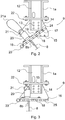
- Figs. 2-5 present simplified, partly sectioned side and front views of a fixing solution of the second ends 8b of the compensating ropes 8 according to the invention on the elevator car 2 side in the fixing phase of the ends of the compensating ropes 8 on the elevator car side and after the fixing.
- the second suspension means 14 that is closer to the viewer is cut completely away so that the parts between the suspension means can be seen clearly enough.
- a fixing base 9 is fixed to the bottom beam 1a of the car sling 1 of the elevator, in as optimal a location as possible in relation to the balance of the elevator car 2 in the longitudinal direction of the bottom beam 1a, by means of bracket elements 12.
- the bracket elements 12 are e.g. beams of a U-profile, which are fixed at their top part to the bottom beam 1a in a vertical position - when being seen fixed together - and into the fixing holes 13 in the bottom part of which bracket elements 12 the fixing base 9 of the second ends 8b of the compensating ropes 8 is fixed e.g. with a bolt-nut fixing.
- the fixing base 9 comprises e.g. two plate-like suspension means 14 that are at a distance from each other and which are fixed at their top ends to the fixing holes 13 of the bracket elements 12, and the bottom edge of which suspension means comprises a plurality of fixing holes 15 at set intervals in row shape.
- the suspension means 14 are asymmetrical in relation to the vertical line of the car sling 1, which asymmetry enables easy adjustment of the second ends of the compensating rope 8 in the depth direction of the elevator car 2 simply by turning the suspension means 14 around 180 degrees in the vertical plane.
- A, for example, plate-like bracket 16 of the wedge housings 20 of the compensating ropes 8, that is bent downwards at its edges is fixed to the holes 15 of the suspension means 14.
- the bracket 16 comprises a plurality of fixing holes 17 disposed at set intervals from each other, the size of which and the distance from each other of which are essentially the same as the size of and the distance from each other of the fixing holes 15 of the suspension means 14. In this way the bracket 16 is arranged to be fixed to the holes 15 of the suspension means 14 by its fixing holes 17 e.g. with a bolt-nut fixing 24.
- the top surface of the bracket 16 comprises a support plate 19, onto the top of which support plate the wedge housings 20 that are used for fixing the second ends 8b of the compensating ropes 8 are fixed in one or more rows side by side.
- the front edge of the bracket 16 comprises a loop 23, by means of which the bracket 16 can be turned around its hinge 18.
- support plates 22 as an additional reinforcement in the structure, which support plates are fixed e.g. with a screw fixing to the bottom surface of the bottom beam 1a in connection with the bracket elements 12.
- Figs. 2 and 4 present a situation in which the second ends 8b of the compensating ropes 8 are just being fixed to the wedge housings 20.
- the bracket 16 is hinged to the fixing holes 15 of the suspension means with one bolt 18, which is disposed in some inner fixing hole 17 of the bracket 16, e.g. in the third fixing hole 17 counting from the second end such that the bolt 18 forms a pivot-type essentially horizontal hinge, around which the bracket 16 can be turned in the vertical plane.
- the bracket 16 and the support plate 19 comprise suitable holes for passing through the second ends 8b of the compensating ropes 8, first in the second direction and then back, which holes are in essentially the same location to each other.
- the bracket 16 When fixing the ends of the compensating ropes 8, the bracket 16 is turned around the hinge formed by the bolt 18 into an inclined attitude to the side of the bottom beam 1a such that the wedge housings 20 point at an angle upwards and away from the bottom beam 1a.
- the bottom corners of the bracket elements 12 are arranged to function as a stop 24 for preventing too much turning of the bracket 16.
- the stop 24 functions as a safety device, so that the weight of the compensating ropes 8 does not manage to pull the bracket 16 in an uncontrolled manner into an angle that is too inclined.
- the bolts other than the bolt 18 that functions as a hinge are detached and the bracket 16 is turned around the hinge formed by the bolt 18 into an inclined position, and also the rope to be replaced is detached and a new rope or new ropes is put in its place, after which the bracket 16 is again turned into its normal position and is locked in position by means of the bolts and fixing nuts 24 disposed in the holes 15 and 17.
- Horizontal adjustment of the fixing of the second ends 8b of the compensating ropes 8 is performed in the depth direction of the elevator car 2, i.e. transversely with respect to the longitudinal direction of the bottom beam 1a, in two different ways. Either with the aforementioned method by turning the suspension means 14 around 180 degrees in the vertical plane before fixing the bracket 16 to the suspension means 14, or by moving the bracket 16 in relation to the fixing holes 15 in the depth direction of the elevator car 2. Thus the adjustment is very versatile.
- horizontal adjustment of the fixing of the second ends 8b of the compensating ropes 8 in the longitudinal direction of the bottom beam 1a is performed by disposing the bracket elements 12 in a suitable location with regard to horizontal adjustment in the longitudinal direction of the bottom beam 1a.
- bracket of the wedge housings can be different to what is presented above.
- it can be one thick plate or e.g. a plate on the bottom surface of which is a plurality of pipes that correspond to the holes in the edges of the plate or that go through the plate.
- the wedge housings can be in more than one row, e.g. in two rows side by side.
- fixing base can be structurally and functionally different to what is described above.
Landscapes
- Engineering & Computer Science (AREA)
- General Engineering & Computer Science (AREA)
- Mechanical Engineering (AREA)
- Lift-Guide Devices, And Elevator Ropes And Cables (AREA)
- Cage And Drive Apparatuses For Elevators (AREA)
Claims (11)
- Verfahren zum Fixieren der Kompensationsseile (8) eines Aufzuges an eine Aufzugskabine (2) und/oder an ein Gegengewicht (4), welcher Aufzug mindestens eine Hebemaschine (6) und eine Hebeseilung (3) aufweist, an der die für einen im Wesentlichen in der Vertikalrichtung verfahrbare Aufzugskabine (2) wie auch das Gegengewicht (4) aufgehängt sind, wobei zwischen der Aufzugskabine (2) und dem Gegengewicht (4) besagte Kompensationsseile (8) derart fixiert sind, dass die ersten Enden (8a) der Kompensationsseile (8) an dem Gegengewicht (4) fixiert sind, von wo die Kompensationsseile (8) nach unten gelassen werden, falls erforderlich, um unter eine Kompensations-Seilscheibe (10a) geführt zu werden, wonach sie wieder nach oben an die Aufzugskabine (2) geführt werden, wo die zweiten Enden (8b) der Kompensationsseile (8) in Verbindung mit der Aufzugskabine (2) mit Hilfe von Keil-Gehäusen (20) fixiert werden, dadurch gekennzeichnet, dass beim Fixieren der Enden (8a, 8b) der Kompensationsseile (8) in Verbindung mit der Aufzugskabine (2) und/oder mit dem Gegengewicht (4) die Keil-Gehäuse (20) in eine geneigte Stellung gedreht werden, bevor die Enden (8a, 8b) der Kompensationsseile (8) in den Keil-Gehäusen (20) angeordnet werden.
- Verfahren gemäß Anspruch 1, dadurch gekennzeichnet, dass beim Fixieren der Enden (8b) der Kompensationsseile (8) in Verbindung mit der Aufzugskabine (2) die Keil-Gehäuse (20) um ein Gelenk (18) in eine geneigte Stellung gedreht werden, derart, dass die Keil-Gehäuse (20) in einem Winkel nach oben zeigen, wonach die Enden (8b) der Kompensationsseile (8) gebogen und in die Keil-Gehäuse (20) zusammen mit den Keilen in einer im Wesentlichen geneigten Stellung bezüglich der Vertikalrichtung geschoben werden.
- Verfahren gemäß Anspruch 1 oder 2, dadurch gekennzeichnet, dass beim Fixieren der Enden (8b) der Kompensationsseile (8) in Verbindung mit der Aufzugskabine (2) die Keil-Gehäuse (20) mit einem Ausleger (16) gedreht werden, der auf dem Sohlenträger (1a) der Aufzugskabine (2) angelenkt ist, und zwar um ein Gelenk (18) in eine geneigte Stellung, wobei die Enden (8b) der Kompensationsseile (8) in den Keil-Gehäusen (20) fixiert werden, und wenn alle Enden (8b) der Kompensationsseile (8) auf diese Weise fixiert sind, der Ausleger (16) um das Gelenk (18) in seine im Wesentlichen horizontale Normalstellung gedreht wird und ebenso in eine Position auf den Haltemitteln (14) fixiert wird, die an dem Sohlenträger (1a) der Aufzugskabine (2) mit Hilfe von Fixierungsmitteln (24) fixiert sind.
- Verfahren gemäß Anspruch 1, 2 oder 3, dadurch gekennzeichnet, dass die Fixier-Lokation der Enden (8b) der Kompensationsseile (8) in der Horizontalrichtung in der Tiefenrichtung der Aufzugskabine (2) durch Bewegen des Auslegers (16) der Keil-Gehäuse (20) in der Tiefenrichtung der Aufzugskabine (2) justiert wird, und/oder durch Drehen der Aufhängemittel (14) um 180 Grad in der Vertikalebene, bevor der Ausleger (16) an den Haltemitteln (14) fixiert wird.
- Einrichtung zum Fixieren von Kompensationsseilen (8) eines Aufzuges an einer Aufzugskabine (2) und/oder an ein Gegengewicht (4), welcher Aufzug mindestens eine Hebemaschine (6) und eine Hebeseilung (3) aufweist, an der die zum Verfahren von im Wesentlichen in der Vertikalrichtung angeordnete Aufzugskabine (2) wie auch das Gegengewicht (4) aufgehängt sind, und wobei zwischen der Aufzugskabine (2) und dem Gegengewicht (4) besagte Kompensationsseile (8) derart fixiert sind, dass die ersten Enden (8a) der Kompensationsseile (8) an dem Gegengewicht (4) fixiert sind, von wo die Kompensationsseile (8) nach unten gelassen sind, um bei Bedarf unter eine Kompensations-Seilscheibe (10a) geführt zu werden, wonach sie wieder nach oben an die Aufzugskabine (2) geführt sind, wo die zweiten Enden (8b) der Kompensationsseile (8) mit Hilfe von Keil-Gehäusen (20) in Verbindung mit der Aufzugskabine (2) fixiert sind, dadurch gekennzeichnet, dass die Keil-Gehäuse (20) dazu angeordnet sind, in eine geneigte Stellung gedreht zu werden, um die Enden (8a, 8b) der Kompensationsseile in Verbindung mit der Aufzugskabine (2) und/oder dem Gegengewicht (4) zu fixieren.
- Einrichtung gemäß Anspruch 5, dadurch gekennzeichnet, dass die Keil-Gehäuse (20) an einer Fixierbasis (9) fixiert sind, die mit einem Gelenk (18) oder entsprechender Drehstruktur versehen ist, um die Fixierbasis (9) in eine bevorzugte Stellung zum Zwecke der Fixierung der zweiten Enden (8a) der Kompensationsseile (8) zu drehen.
- Einrichtung gemäß Anspruch 6, dadurch gekennzeichnet, dass die Fixierbasis (9) einen Ausleger (16) der Keil-Gehäuse (20) aufweist, welcher Ausleger von dem Sohlenträger (1a) des Kabinenrahmens (1) der Aufzugskabine (2) gehalten wird, zumindest über eine Mehrzahl von Haltemitteln (14), die mit Fixierlöchern (15) versehen sind.
- Einrichtung gemäß Anspruch 7, dadurch gekennzeichnet, dass der Ausleger (16) der Keil-Gehäuse (20) eine Mehrzahl an Fixierlöchern (17) aufweist, die zu gesetzten Intervallen zueinander angeordnet sind, wobei deren Größe und der Abstand zueinander im Wesentlichen gleichgroß ist zur Größe und zu dem gegenseitigen Abstand der Fixierlöcher (15) der Haltemittel (14).
- Einrichtung gemäß Anspruch 7 oder 8, dadurch gekennzeichnet, dass der Ausleger (16) angeordnet ist, um an den Haltemitteln (14) zu Stufen-Intervallen fixiert zu werden, welche Intervalle dem Abstand zwischen den Fixierlöchern (15 und 1 7) entsprechen.
- Einrichtung gemäß einem der vorangehenden Ansprüche 7 - 9, dadurch gekennzeichnet, dass Auslegerelemente (12), die in ihrer Position in der Längsrichtung des Sohlenträgers (1a) einjustiert werden können, an dem Sohlenträger (1a) der Aufzugskabine (2) fixiert sind, an welche Auslegerelemente die Haltemittel (14) an deren oberen Enden fixiert sind.
- Einrichtung gemäß Anspruch 10, dadurch gekennzeichnet, dass die Sohlenecke der Auslegerelemente (12) angeordnet ist, um als ein Anschlag (24) zu funktionieren, um ein zu weites Drehen des Auslegers (16) zu verhindern.
Applications Claiming Priority (2)
| Application Number | Priority Date | Filing Date | Title |
|---|---|---|---|
| FI20080464A FI120830B (fi) | 2008-08-13 | 2008-08-13 | Menetelmä ja järjestely hissin kompensaatioköysien kiinnittämiseksi |
| PCT/FI2009/000075 WO2010018299A1 (en) | 2008-08-13 | 2009-08-11 | Method and arrangement for fixing the compensating ropes of an elevator |
Publications (3)
| Publication Number | Publication Date |
|---|---|
| EP2323942A1 EP2323942A1 (de) | 2011-05-25 |
| EP2323942A4 EP2323942A4 (de) | 2015-01-07 |
| EP2323942B1 true EP2323942B1 (de) | 2017-10-04 |
Family
ID=39735598
Family Applications (1)
| Application Number | Title | Priority Date | Filing Date |
|---|---|---|---|
| EP09806487.6A Not-in-force EP2323942B1 (de) | 2008-08-13 | 2009-08-11 | Verfahren und anordnung zur befestigung der ausgleichsseile eines aufzugs |
Country Status (7)
| Country | Link |
|---|---|
| US (1) | US8360212B2 (de) |
| EP (1) | EP2323942B1 (de) |
| CN (1) | CN102105380B (de) |
| AU (1) | AU2009281030B2 (de) |
| EA (1) | EA018002B1 (de) |
| FI (1) | FI120830B (de) |
| WO (1) | WO2010018299A1 (de) |
Families Citing this family (8)
| Publication number | Priority date | Publication date | Assignee | Title |
|---|---|---|---|---|
| FI122065B (fi) * | 2009-12-21 | 2011-08-15 | Kone Corp | Menetelmä hissiköysien vaihtamiseksi ja hissi |
| CN104944249A (zh) * | 2014-03-26 | 2015-09-30 | 扬州尼尔工程塑料有限公司 | 新型电梯补偿链绳轮 |
| FI127314B (en) | 2015-04-30 | 2018-03-29 | Kone Corp | Procedure for handling and modernizing lift lines and arrangements for dismantling lift lines |
| CN105366484A (zh) * | 2015-11-02 | 2016-03-02 | 康力电梯股份有限公司 | 一种新型电梯顶部承重梁 |
| CN112867689B (zh) * | 2018-10-24 | 2022-09-13 | 株式会社日立制作所 | 电梯以及补偿绳索支承机构 |
| CN110626912B (zh) * | 2019-09-24 | 2020-11-17 | 巨龙电梯有限公司 | 一种高速梯用补偿绳悬挂装置 |
| CN111285225B (zh) * | 2020-03-25 | 2024-12-27 | 申芝电梯有限公司 | 一种电梯补偿缆的悬挂装置 |
| CN113460831B (zh) * | 2021-07-08 | 2025-02-25 | 浙江优迈重工机械有限公司 | 电梯补偿装置 |
Family Cites Families (12)
| Publication number | Priority date | Publication date | Assignee | Title |
|---|---|---|---|---|
| JPS55166552A (en) * | 1979-06-11 | 1980-12-25 | Hitachi Ltd | Mounting device for balance compensating cable of elevator |
| US5172782A (en) * | 1991-11-15 | 1992-12-22 | Otis Elevator Company | Pivot mount of elevator load-weighing at car hitch |
| JP3300061B2 (ja) * | 1991-11-15 | 2002-07-08 | オーチス エレベータ カンパニー | エレベータ車両の負荷計測用組立体 |
| JPH06255945A (ja) * | 1993-03-03 | 1994-09-13 | Otis Elevator Co | 釣り合いロープを有するエレベーター |
| US5353893A (en) * | 1993-07-12 | 1994-10-11 | Otis Elevator Company | Elevator cab and/or counterweight compensation rope hitch assembly |
| JPH07228448A (ja) * | 1994-02-17 | 1995-08-29 | Toshiba Corp | エレベータのコンペンロープ取付構造 |
| CN2392753Y (zh) * | 1999-09-28 | 2000-08-23 | 中国迅达电梯有限公司 | 带补偿钢索的升降机 |
| JP2001247277A (ja) * | 2000-02-09 | 2001-09-11 | Otis Elevator Co | デッドエンドヒッチ |
| US6854164B2 (en) * | 2003-01-28 | 2005-02-15 | Thyssen Elevator Capital Corp | Termination device for an aramid-based elevator rope |
| US7946390B2 (en) * | 2003-05-30 | 2011-05-24 | Otis Elevator Company | Tie-down compensation for an elevator system |
| JP4528017B2 (ja) * | 2004-04-26 | 2010-08-18 | 三菱電機株式会社 | エレベータの釣合いロープの制振装置 |
| JPWO2006126276A1 (ja) * | 2005-05-27 | 2008-12-25 | 三菱電機株式会社 | エレベータのロープソケッティング装置 |
-
2008
- 2008-08-13 FI FI20080464A patent/FI120830B/fi active IP Right Grant
-
2009
- 2009-08-11 CN CN200980129417.5A patent/CN102105380B/zh not_active Expired - Fee Related
- 2009-08-11 EA EA201100085A patent/EA018002B1/ru not_active IP Right Cessation
- 2009-08-11 AU AU2009281030A patent/AU2009281030B2/en not_active Ceased
- 2009-08-11 EP EP09806487.6A patent/EP2323942B1/de not_active Not-in-force
- 2009-08-11 WO PCT/FI2009/000075 patent/WO2010018299A1/en not_active Ceased
-
2011
- 2011-01-10 US US12/987,643 patent/US8360212B2/en not_active Expired - Fee Related
Non-Patent Citations (1)
| Title |
|---|
| None * |
Also Published As
| Publication number | Publication date |
|---|---|
| CN102105380A (zh) | 2011-06-22 |
| CN102105380B (zh) | 2014-01-29 |
| EP2323942A4 (de) | 2015-01-07 |
| EP2323942A1 (de) | 2011-05-25 |
| US8360212B2 (en) | 2013-01-29 |
| AU2009281030B2 (en) | 2016-01-28 |
| FI20080464A0 (fi) | 2008-08-13 |
| AU2009281030A1 (en) | 2010-02-18 |
| WO2010018299A1 (en) | 2010-02-18 |
| FI20080464L (fi) | 2010-02-14 |
| EA018002B1 (ru) | 2013-04-30 |
| FI120830B (fi) | 2010-03-31 |
| EA201100085A1 (ru) | 2011-10-31 |
| US20110162915A1 (en) | 2011-07-07 |
| HK1158602A1 (en) | 2012-07-20 |
Similar Documents
| Publication | Publication Date | Title |
|---|---|---|
| US8360212B2 (en) | Method and arrangement for fixing the compensating ropes of an elevator | |
| FI127314B (en) | Procedure for handling and modernizing lift lines and arrangements for dismantling lift lines | |
| EP2493803B1 (de) | Befestigungsvorrichtung für die hebemaschine eines aufzugs und verfahren zur installation einer hebemaschine für einen aufzug | |
| EP2844600B1 (de) | Verfahren zur installation einer maschine in einer aufzugsanlage | |
| KR20180132821A (ko) | 엘리베이터의 권상기 설치 방법 | |
| EA016364B1 (ru) | Механизм для подачи каната к ограничителю скорости | |
| AU2005200039B2 (en) | Drive for a lift installation and method of converting a drive in a lift installation | |
| JP6215093B2 (ja) | エレベーター及びそれに用いるコンペンプーリ | |
| JP2008290828A (ja) | エレベーター装置 | |
| KR20130122643A (ko) | 엘리베이터의 엘리베이터칸 | |
| JP5940713B1 (ja) | エレベータのコンペンシーブ支持構造体 | |
| JP2011190047A (ja) | エレベータ装置 | |
| KR100780499B1 (ko) | 기계실이 없는 엘리베이터 시스템 | |
| JP6336225B2 (ja) | エレベータ装置 | |
| WO2020255262A1 (ja) | エレベーターの非常止め装置の交換方法およびエレベーターの非常止め装置の交換装置 | |
| JP2012201497A (ja) | マシンベッド及び揚重装置 | |
| WO2013004899A1 (en) | Elevator, rope anchorage assembly for an elevator, and method for modernizing an elevator | |
| HK1158602B (en) | Method and arrangement for fixing the compensating ropes of an elevator | |
| CN101177223A (zh) | 电梯设备 | |
| JP7733790B1 (ja) | エレベータの釣合錘装置及びその組み立て方法 | |
| JPH08217361A (ja) | エレベータのつり合いおもり脱レール防止装置 | |
| JP7757512B1 (ja) | エレベータの釣合錘装置 | |
| EP1717184B1 (de) | Aufzug | |
| JP7799555B2 (ja) | エレベータ装置 | |
| JP7614385B2 (ja) | エレベーターのガイドレール装置及びその据付方法 |
Legal Events
| Date | Code | Title | Description |
|---|---|---|---|
| PUAI | Public reference made under article 153(3) epc to a published international application that has entered the european phase |
Free format text: ORIGINAL CODE: 0009012 |
|
| 17P | Request for examination filed |
Effective date: 20110304 |
|
| AK | Designated contracting states |
Kind code of ref document: A1 Designated state(s): AT BE BG CH CY CZ DE DK EE ES FI FR GB GR HR HU IE IS IT LI LT LU LV MC MK MT NL NO PL PT RO SE SI SK SM TR |
|
| AX | Request for extension of the european patent |
Extension state: AL BA RS |
|
| DAX | Request for extension of the european patent (deleted) | ||
| A4 | Supplementary search report drawn up and despatched |
Effective date: 20141208 |
|
| RIC1 | Information provided on ipc code assigned before grant |
Ipc: F16G 11/04 20060101ALI20141202BHEP Ipc: B66B 7/08 20060101AFI20141202BHEP |
|
| 17Q | First examination report despatched |
Effective date: 20160201 |
|
| GRAP | Despatch of communication of intention to grant a patent |
Free format text: ORIGINAL CODE: EPIDOSNIGR1 |
|
| INTG | Intention to grant announced |
Effective date: 20170509 |
|
| GRAS | Grant fee paid |
Free format text: ORIGINAL CODE: EPIDOSNIGR3 |
|
| GRAA | (expected) grant |
Free format text: ORIGINAL CODE: 0009210 |
|
| AK | Designated contracting states |
Kind code of ref document: B1 Designated state(s): AT BE BG CH CY CZ DE DK EE ES FI FR GB GR HR HU IE IS IT LI LT LU LV MC MK MT NL NO PL PT RO SE SI SK SM TR |
|
| REG | Reference to a national code |
Ref country code: GB Ref legal event code: FG4D |
|
| REG | Reference to a national code |
Ref country code: CH Ref legal event code: EP |
|
| REG | Reference to a national code |
Ref country code: AT Ref legal event code: REF Ref document number: 933809 Country of ref document: AT Kind code of ref document: T Effective date: 20171015 |
|
| REG | Reference to a national code |
Ref country code: IE Ref legal event code: FG4D |
|
| REG | Reference to a national code |
Ref country code: DE Ref legal event code: R096 Ref document number: 602009048719 Country of ref document: DE |
|
| REG | Reference to a national code |
Ref country code: NL Ref legal event code: MP Effective date: 20171004 |
|
| REG | Reference to a national code |
Ref country code: LT Ref legal event code: MG4D |
|
| REG | Reference to a national code |
Ref country code: AT Ref legal event code: MK05 Ref document number: 933809 Country of ref document: AT Kind code of ref document: T Effective date: 20171004 |
|
| PG25 | Lapsed in a contracting state [announced via postgrant information from national office to epo] |
Ref country code: NL Free format text: LAPSE BECAUSE OF FAILURE TO SUBMIT A TRANSLATION OF THE DESCRIPTION OR TO PAY THE FEE WITHIN THE PRESCRIBED TIME-LIMIT Effective date: 20171004 |
|
| PG25 | Lapsed in a contracting state [announced via postgrant information from national office to epo] |
Ref country code: FI Free format text: LAPSE BECAUSE OF FAILURE TO SUBMIT A TRANSLATION OF THE DESCRIPTION OR TO PAY THE FEE WITHIN THE PRESCRIBED TIME-LIMIT Effective date: 20171004 Ref country code: SE Free format text: LAPSE BECAUSE OF FAILURE TO SUBMIT A TRANSLATION OF THE DESCRIPTION OR TO PAY THE FEE WITHIN THE PRESCRIBED TIME-LIMIT Effective date: 20171004 Ref country code: NO Free format text: LAPSE BECAUSE OF FAILURE TO SUBMIT A TRANSLATION OF THE DESCRIPTION OR TO PAY THE FEE WITHIN THE PRESCRIBED TIME-LIMIT Effective date: 20180104 Ref country code: LT Free format text: LAPSE BECAUSE OF FAILURE TO SUBMIT A TRANSLATION OF THE DESCRIPTION OR TO PAY THE FEE WITHIN THE PRESCRIBED TIME-LIMIT Effective date: 20171004 Ref country code: ES Free format text: LAPSE BECAUSE OF FAILURE TO SUBMIT A TRANSLATION OF THE DESCRIPTION OR TO PAY THE FEE WITHIN THE PRESCRIBED TIME-LIMIT Effective date: 20171004 |
|
| PG25 | Lapsed in a contracting state [announced via postgrant information from national office to epo] |
Ref country code: GR Free format text: LAPSE BECAUSE OF FAILURE TO SUBMIT A TRANSLATION OF THE DESCRIPTION OR TO PAY THE FEE WITHIN THE PRESCRIBED TIME-LIMIT Effective date: 20180105 Ref country code: HR Free format text: LAPSE BECAUSE OF FAILURE TO SUBMIT A TRANSLATION OF THE DESCRIPTION OR TO PAY THE FEE WITHIN THE PRESCRIBED TIME-LIMIT Effective date: 20171004 Ref country code: IS Free format text: LAPSE BECAUSE OF FAILURE TO SUBMIT A TRANSLATION OF THE DESCRIPTION OR TO PAY THE FEE WITHIN THE PRESCRIBED TIME-LIMIT Effective date: 20180204 Ref country code: LV Free format text: LAPSE BECAUSE OF FAILURE TO SUBMIT A TRANSLATION OF THE DESCRIPTION OR TO PAY THE FEE WITHIN THE PRESCRIBED TIME-LIMIT Effective date: 20171004 Ref country code: AT Free format text: LAPSE BECAUSE OF FAILURE TO SUBMIT A TRANSLATION OF THE DESCRIPTION OR TO PAY THE FEE WITHIN THE PRESCRIBED TIME-LIMIT Effective date: 20171004 Ref country code: BG Free format text: LAPSE BECAUSE OF FAILURE TO SUBMIT A TRANSLATION OF THE DESCRIPTION OR TO PAY THE FEE WITHIN THE PRESCRIBED TIME-LIMIT Effective date: 20180104 |
|
| REG | Reference to a national code |
Ref country code: DE Ref legal event code: R097 Ref document number: 602009048719 Country of ref document: DE |
|
| PG25 | Lapsed in a contracting state [announced via postgrant information from national office to epo] |
Ref country code: DK Free format text: LAPSE BECAUSE OF FAILURE TO SUBMIT A TRANSLATION OF THE DESCRIPTION OR TO PAY THE FEE WITHIN THE PRESCRIBED TIME-LIMIT Effective date: 20171004 Ref country code: SK Free format text: LAPSE BECAUSE OF FAILURE TO SUBMIT A TRANSLATION OF THE DESCRIPTION OR TO PAY THE FEE WITHIN THE PRESCRIBED TIME-LIMIT Effective date: 20171004 Ref country code: CZ Free format text: LAPSE BECAUSE OF FAILURE TO SUBMIT A TRANSLATION OF THE DESCRIPTION OR TO PAY THE FEE WITHIN THE PRESCRIBED TIME-LIMIT Effective date: 20171004 Ref country code: EE Free format text: LAPSE BECAUSE OF FAILURE TO SUBMIT A TRANSLATION OF THE DESCRIPTION OR TO PAY THE FEE WITHIN THE PRESCRIBED TIME-LIMIT Effective date: 20171004 |
|
| PLBE | No opposition filed within time limit |
Free format text: ORIGINAL CODE: 0009261 |
|
| STAA | Information on the status of an ep patent application or granted ep patent |
Free format text: STATUS: NO OPPOSITION FILED WITHIN TIME LIMIT |
|
| REG | Reference to a national code |
Ref country code: FR Ref legal event code: PLFP Year of fee payment: 10 |
|
| PG25 | Lapsed in a contracting state [announced via postgrant information from national office to epo] |
Ref country code: PL Free format text: LAPSE BECAUSE OF FAILURE TO SUBMIT A TRANSLATION OF THE DESCRIPTION OR TO PAY THE FEE WITHIN THE PRESCRIBED TIME-LIMIT Effective date: 20171004 Ref country code: RO Free format text: LAPSE BECAUSE OF FAILURE TO SUBMIT A TRANSLATION OF THE DESCRIPTION OR TO PAY THE FEE WITHIN THE PRESCRIBED TIME-LIMIT Effective date: 20171004 Ref country code: IT Free format text: LAPSE BECAUSE OF FAILURE TO SUBMIT A TRANSLATION OF THE DESCRIPTION OR TO PAY THE FEE WITHIN THE PRESCRIBED TIME-LIMIT Effective date: 20171004 Ref country code: SM Free format text: LAPSE BECAUSE OF FAILURE TO SUBMIT A TRANSLATION OF THE DESCRIPTION OR TO PAY THE FEE WITHIN THE PRESCRIBED TIME-LIMIT Effective date: 20171004 |
|
| 26N | No opposition filed |
Effective date: 20180705 |
|
| PG25 | Lapsed in a contracting state [announced via postgrant information from national office to epo] |
Ref country code: SI Free format text: LAPSE BECAUSE OF FAILURE TO SUBMIT A TRANSLATION OF THE DESCRIPTION OR TO PAY THE FEE WITHIN THE PRESCRIBED TIME-LIMIT Effective date: 20171004 |
|
| PG25 | Lapsed in a contracting state [announced via postgrant information from national office to epo] |
Ref country code: MC Free format text: LAPSE BECAUSE OF FAILURE TO SUBMIT A TRANSLATION OF THE DESCRIPTION OR TO PAY THE FEE WITHIN THE PRESCRIBED TIME-LIMIT Effective date: 20171004 |
|
| REG | Reference to a national code |
Ref country code: CH Ref legal event code: PL |
|
| PG25 | Lapsed in a contracting state [announced via postgrant information from national office to epo] |
Ref country code: LU Free format text: LAPSE BECAUSE OF NON-PAYMENT OF DUE FEES Effective date: 20180811 Ref country code: LI Free format text: LAPSE BECAUSE OF NON-PAYMENT OF DUE FEES Effective date: 20180831 Ref country code: CH Free format text: LAPSE BECAUSE OF NON-PAYMENT OF DUE FEES Effective date: 20180831 |
|
| REG | Reference to a national code |
Ref country code: BE Ref legal event code: MM Effective date: 20180831 |
|
| REG | Reference to a national code |
Ref country code: IE Ref legal event code: MM4A |
|
| PG25 | Lapsed in a contracting state [announced via postgrant information from national office to epo] |
Ref country code: IE Free format text: LAPSE BECAUSE OF NON-PAYMENT OF DUE FEES Effective date: 20180811 |
|
| PG25 | Lapsed in a contracting state [announced via postgrant information from national office to epo] |
Ref country code: BE Free format text: LAPSE BECAUSE OF NON-PAYMENT OF DUE FEES Effective date: 20180831 |
|
| PG25 | Lapsed in a contracting state [announced via postgrant information from national office to epo] |
Ref country code: MT Free format text: LAPSE BECAUSE OF NON-PAYMENT OF DUE FEES Effective date: 20180811 |
|
| PG25 | Lapsed in a contracting state [announced via postgrant information from national office to epo] |
Ref country code: TR Free format text: LAPSE BECAUSE OF FAILURE TO SUBMIT A TRANSLATION OF THE DESCRIPTION OR TO PAY THE FEE WITHIN THE PRESCRIBED TIME-LIMIT Effective date: 20171004 |
|
| PG25 | Lapsed in a contracting state [announced via postgrant information from national office to epo] |
Ref country code: HU Free format text: LAPSE BECAUSE OF FAILURE TO SUBMIT A TRANSLATION OF THE DESCRIPTION OR TO PAY THE FEE WITHIN THE PRESCRIBED TIME-LIMIT; INVALID AB INITIO Effective date: 20090811 Ref country code: PT Free format text: LAPSE BECAUSE OF FAILURE TO SUBMIT A TRANSLATION OF THE DESCRIPTION OR TO PAY THE FEE WITHIN THE PRESCRIBED TIME-LIMIT Effective date: 20171004 |
|
| PG25 | Lapsed in a contracting state [announced via postgrant information from national office to epo] |
Ref country code: CY Free format text: LAPSE BECAUSE OF FAILURE TO SUBMIT A TRANSLATION OF THE DESCRIPTION OR TO PAY THE FEE WITHIN THE PRESCRIBED TIME-LIMIT Effective date: 20171004 Ref country code: MK Free format text: LAPSE BECAUSE OF NON-PAYMENT OF DUE FEES Effective date: 20171004 |
|
| PGFP | Annual fee paid to national office [announced via postgrant information from national office to epo] |
Ref country code: FR Payment date: 20210819 Year of fee payment: 13 |
|
| PGFP | Annual fee paid to national office [announced via postgrant information from national office to epo] |
Ref country code: DE Payment date: 20210819 Year of fee payment: 13 Ref country code: GB Payment date: 20210820 Year of fee payment: 13 |
|
| REG | Reference to a national code |
Ref country code: DE Ref legal event code: R119 Ref document number: 602009048719 Country of ref document: DE |
|
| GBPC | Gb: european patent ceased through non-payment of renewal fee |
Effective date: 20220811 |
|
| PG25 | Lapsed in a contracting state [announced via postgrant information from national office to epo] |
Ref country code: FR Free format text: LAPSE BECAUSE OF NON-PAYMENT OF DUE FEES Effective date: 20220831 Ref country code: DE Free format text: LAPSE BECAUSE OF NON-PAYMENT OF DUE FEES Effective date: 20230301 |
|
| PG25 | Lapsed in a contracting state [announced via postgrant information from national office to epo] |
Ref country code: GB Free format text: LAPSE BECAUSE OF NON-PAYMENT OF DUE FEES Effective date: 20220811 |