EP2323794B1 - Schneidwerkzeug und runder doppelseitiger schneideinsatz dafür - Google Patents
Schneidwerkzeug und runder doppelseitiger schneideinsatz dafür Download PDFInfo
- Publication number
- EP2323794B1 EP2323794B1 EP09787542.1A EP09787542A EP2323794B1 EP 2323794 B1 EP2323794 B1 EP 2323794B1 EP 09787542 A EP09787542 A EP 09787542A EP 2323794 B1 EP2323794 B1 EP 2323794B1
- Authority
- EP
- European Patent Office
- Prior art keywords
- cutting
- insert
- axis
- cutting edge
- Prior art date
- Legal status (The legal status is an assumption and is not a legal conclusion. Google has not performed a legal analysis and makes no representation as to the accuracy of the status listed.)
- Active
Links
- 238000005520 cutting process Methods 0.000 title claims description 351
- 230000002093 peripheral effect Effects 0.000 claims description 21
- 230000000717 retained effect Effects 0.000 claims description 12
- 230000001154 acute effect Effects 0.000 claims description 8
- 102100037224 Noncompact myelin-associated protein Human genes 0.000 claims description 3
- 101710184695 Noncompact myelin-associated protein Proteins 0.000 claims description 3
- 230000014759 maintenance of location Effects 0.000 claims description 2
- 238000003754 machining Methods 0.000 description 11
- 238000010276 construction Methods 0.000 description 4
- 239000000463 material Substances 0.000 description 2
- 238000003801 milling Methods 0.000 description 2
- 101001005165 Bos taurus Lens fiber membrane intrinsic protein Proteins 0.000 description 1
- 101000964052 Rattus norvegicus 5-hydroxytryptamine receptor 5B Proteins 0.000 description 1
- 229910045601 alloy Inorganic materials 0.000 description 1
- 239000000956 alloy Substances 0.000 description 1
- 230000004075 alteration Effects 0.000 description 1
- 239000000919 ceramic Substances 0.000 description 1
- 230000001419 dependent effect Effects 0.000 description 1
- 238000001746 injection moulding Methods 0.000 description 1
- 238000000034 method Methods 0.000 description 1
- 238000012986 modification Methods 0.000 description 1
- 230000004048 modification Effects 0.000 description 1
- 239000000843 powder Substances 0.000 description 1
- 238000003825 pressing Methods 0.000 description 1
- 238000005245 sintering Methods 0.000 description 1
Images


Classifications
-
- B—PERFORMING OPERATIONS; TRANSPORTING
- B23—MACHINE TOOLS; METAL-WORKING NOT OTHERWISE PROVIDED FOR
- B23C—MILLING
- B23C5/00—Milling-cutters
- B23C5/16—Milling-cutters characterised by physical features other than shape
- B23C5/20—Milling-cutters characterised by physical features other than shape with removable cutter bits or teeth or cutting inserts
- B23C5/202—Plate-like cutting inserts with special form
- B23C5/205—Plate-like cutting inserts with special form characterised by chip-breakers of special form
-
- B—PERFORMING OPERATIONS; TRANSPORTING
- B23—MACHINE TOOLS; METAL-WORKING NOT OTHERWISE PROVIDED FOR
- B23C—MILLING
- B23C5/00—Milling-cutters
- B23C5/16—Milling-cutters characterised by physical features other than shape
- B23C5/20—Milling-cutters characterised by physical features other than shape with removable cutter bits or teeth or cutting inserts
- B23C5/202—Plate-like cutting inserts with special form
-
- B—PERFORMING OPERATIONS; TRANSPORTING
- B23—MACHINE TOOLS; METAL-WORKING NOT OTHERWISE PROVIDED FOR
- B23B—TURNING; BORING
- B23B27/00—Tools for turning or boring machines; Tools of a similar kind in general; Accessories therefor
- B23B27/14—Cutting tools of which the bits or tips or cutting inserts are of special material
- B23B27/16—Cutting tools of which the bits or tips or cutting inserts are of special material with exchangeable cutting bits or cutting inserts, e.g. able to be clamped
-
- B—PERFORMING OPERATIONS; TRANSPORTING
- B23—MACHINE TOOLS; METAL-WORKING NOT OTHERWISE PROVIDED FOR
- B23C—MILLING
- B23C5/00—Milling-cutters
- B23C5/16—Milling-cutters characterised by physical features other than shape
- B23C5/20—Milling-cutters characterised by physical features other than shape with removable cutter bits or teeth or cutting inserts
- B23C5/22—Securing arrangements for bits or teeth or cutting inserts
- B23C5/2204—Securing arrangements for bits or teeth or cutting inserts with cutting inserts clamped against the walls of the recess in the cutter body by a clamping member acting upon the wall of a hole in the insert
- B23C5/2208—Securing arrangements for bits or teeth or cutting inserts with cutting inserts clamped against the walls of the recess in the cutter body by a clamping member acting upon the wall of a hole in the insert for plate-like cutting inserts
- B23C5/2213—Securing arrangements for bits or teeth or cutting inserts with cutting inserts clamped against the walls of the recess in the cutter body by a clamping member acting upon the wall of a hole in the insert for plate-like cutting inserts having a special shape
-
- B—PERFORMING OPERATIONS; TRANSPORTING
- B23—MACHINE TOOLS; METAL-WORKING NOT OTHERWISE PROVIDED FOR
- B23C—MILLING
- B23C2200/00—Details of milling cutting inserts
- B23C2200/12—Side or flank surfaces
- B23C2200/128—Side or flank surfaces with one or more grooves
-
- B—PERFORMING OPERATIONS; TRANSPORTING
- B23—MACHINE TOOLS; METAL-WORKING NOT OTHERWISE PROVIDED FOR
- B23C—MILLING
- B23C2200/00—Details of milling cutting inserts
- B23C2200/20—Top or side views of the cutting edge
- B23C2200/201—Details of the nose radius and immediately surrounding areas
-
- B—PERFORMING OPERATIONS; TRANSPORTING
- B23—MACHINE TOOLS; METAL-WORKING NOT OTHERWISE PROVIDED FOR
- B23C—MILLING
- B23C2200/00—Details of milling cutting inserts
- B23C2200/20—Top or side views of the cutting edge
- B23C2200/203—Curved cutting edges
-
- B—PERFORMING OPERATIONS; TRANSPORTING
- B23—MACHINE TOOLS; METAL-WORKING NOT OTHERWISE PROVIDED FOR
- B23C—MILLING
- B23C2210/00—Details of milling cutters
- B23C2210/16—Fixation of inserts or cutting bits in the tool
- B23C2210/168—Seats for cutting inserts, supports for replacable cutting bits
-
- Y—GENERAL TAGGING OF NEW TECHNOLOGICAL DEVELOPMENTS; GENERAL TAGGING OF CROSS-SECTIONAL TECHNOLOGIES SPANNING OVER SEVERAL SECTIONS OF THE IPC; TECHNICAL SUBJECTS COVERED BY FORMER USPC CROSS-REFERENCE ART COLLECTIONS [XRACs] AND DIGESTS
- Y10—TECHNICAL SUBJECTS COVERED BY FORMER USPC
- Y10T—TECHNICAL SUBJECTS COVERED BY FORMER US CLASSIFICATION
- Y10T407/00—Cutters, for shaping
- Y10T407/19—Rotary cutting tool
- Y10T407/1906—Rotary cutting tool including holder [i.e., head] having seat for inserted tool
- Y10T407/1908—Face or end mill
- Y10T407/1924—Specified tool shape
-
- Y—GENERAL TAGGING OF NEW TECHNOLOGICAL DEVELOPMENTS; GENERAL TAGGING OF CROSS-SECTIONAL TECHNOLOGIES SPANNING OVER SEVERAL SECTIONS OF THE IPC; TECHNICAL SUBJECTS COVERED BY FORMER USPC CROSS-REFERENCE ART COLLECTIONS [XRACs] AND DIGESTS
- Y10—TECHNICAL SUBJECTS COVERED BY FORMER USPC
- Y10T—TECHNICAL SUBJECTS COVERED BY FORMER US CLASSIFICATION
- Y10T407/00—Cutters, for shaping
- Y10T407/23—Cutters, for shaping including tool having plural alternatively usable cutting edges
Definitions
- the present invention relates to a milling cutting insert having rounded cutting edges according to the preamble of claim 1 and a cutting tool comprising such an insert.
- An exemplary cutting insert is known from US 3 821 836 A .
- the final machining stage of the internal surface of the turbine blade is typically done by means of milling cutting inserts having round cutting edges.
- the total usable sector used to cut by such a cutting insert is usually greater than 120°, therefore, the cutting insert may be indexed only two times since a third indexing would not be able to utilize a full range sector, i.e., a cutting edge spanning to more than 120°.
- Round double sided cutting inserts are typically ceramic inserts and are devoid a central through bore for the passage of a clamping screw.
- the lack of a through bore is a disadvantage since it requires utilizing a more complex and expensive retaining system.
- a cutting insert for retention in a rotating cutting tool having an axis of rotation in accordance with claim 1.
- the cutting tool 10 has a longitudinal axis of rotation A defining a front-to-rear direction of the cutting tool 10 and a direction of rotation R.
- the cutting tool 10 comprises a tool body 12 having a plurality of insert pockets 14 formed in a front end 16 of the tool body 12.
- a cutting insert 18 is retained in each of the insert pockets 14 by means of a clamping screw 20.
- the cutting insert 18 may be preferably made from cemented carbide powders by pressing and sintering or by injection molding techniques.
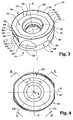
- the cutting insert 18 comprises an upper surface 22, defining a first reference plane P1 , a lower surface 24 , defining a second reference plane P2, and a peripheral surface 26 extending between the upper surface 22 and the lower surface 24.
- the upper surface 22 and the lower surface 24 constitute end surfaces 28 of the cutting insert 18 .
- the end surfaces 28 may be identical, and the first reference plane P1 may be parallel to the second reference plane P2.
- the cutting insert 18 is provided with a through bore 30 having a through bore axis B.
- the through bore 30 extends between the upper surface 22 and the lower surface 24.
- the cutting insert 18 may have 180° rotational symmetry around the through bore axis B.
- each of the end surfaces 28 may comprise a first main cutting edge 32 and a second main cutting edge 34.
- the first main cutting edge 32 and the second main cutting edge 34 may be identical.
- the cutting edges are formed at the junction between each end surface 28 and the peripheral surface 26.
- Fig. 5 is an end view of the cutting insert 18 showing the cutting edges of both end surfaces without showing the through bore 30.
- the cutting edges of the upper surface 22 are shown in solid lines and the cutting edges of the lower surface 2 4 are shown in dashed lines.
- the first and second main cutting edges 32, 34 of the upper surface 22 are angularly shifted with respect to the first and second main cutting edges 32' , 34' of the lower surface 24.
- the main cutting edges of a given end surface 28 do not overlap the main cutting edges of the opposite end surface 28.
- Each of the cutting edges 32, 34 has a cutting edge axis C associated therewith.
- the cutting edge axis C is located in a mid portion 35 of the cutting edge and extends parallel to an axis of symmetry B which will be later described.
- the mid portion 35 refers to a region including the geometrical center of the curved cutting edge and not necessarily to the actual geometrical center of the curved cutting edge.
- each of the curved cutting edges 32, 34 of one end surface 28 is rotated about its associated cutting edge axis C relative to the opposite curved cutting edge 32', 34' of the other end surface 28.
- the first main cutting edge 32 has a first radius of curvature R1 with respect to a first cutting edge axis A1
- the second main cutting edge 34 has a second radius of curvature R2 with respect to a second cutting edge axis A2.
- the first cutting edge axis A1 and the second cutting edge axis A2 may be parallel to the through bore axis B and located at opposite sides thereof.
- the first cutting edge axis A1 is located a first distance D1 from the second main cutting edge 34
- the through bore axis B is located a second distance D2 from the second main cutting edge 34
- the first distance D1 is smaller than the second distance D2.
- the first cutting edge axis A1 is located closer to the second main cutting edge 34 than the through bore axis B.
- the second cutting edge axis A2 is located closer to the first main cutting edge 32 than the through bore axis B.
- the first main cutting edge 32 and the second main cutting edge 34 do not have to follow a radius of curvature, and they may be curved in other forms.
- the first main cutting edge 32 and the second main cutting edge 34 may follow a major first radius of curvature MR11 along a major portion MP11 thereof and a minor second radius of curvature MR21 along a minor portion M P21 thereof.
- the major first radius of curvature MR11 may be different than the minor second radius of curvature MR21 .
- the major first radius of curvature MR11 may extend along a relatively large angle, represented by the major portion MP11 , for example, 120°, wherein the minor second radius of curvature MR21 may extend along a smaller angle, represented by the minor portion MP21, for example, 20°.
- This embodiment is shown with respect to only one main cutting edge, in this case, with respect to the second main cutting edge. However, the embodiment may be equally applicable to the first and second main cutting edges.
- the major first radius of curvature MR12 may extend along a relatively large angle MP12, for example, 140°, wherein the minor second radius of curvature MR22 may extend along a much smaller angle MP22, for example, 1° to 10°.
- This embodiment is shown with respect to only one main cutting edge, in this case, with respect to the first main cutting edge. However, the embodiment may be equally applicable to the first and second main cutting edges.
- first main cutting edge 32 and the second main cutting edge 34 are formed from several sections (not shown in the figures) that have different radii of curvature and merge with each other to form a continuously curved main cutting edge.
- the first main cutting edge 32 has a leading end 36 and a trailing end 38.
- the second main cutting edge 34 has a leading end 40 and a trailing end 42.
- a first secondary cutting edge 44 merges, at a leading end 46 thereof, with the leading end 36 of the first main cutting edge 32, and, at a trailing end 48 thereof, with the trailing end 42 of the second main cutting edge 34.
- a second secondary cutting edge 50 merges, at a leading end 52 thereof, with the leading end 40 of the second main cutting edge 34, and, at a trailing end 54 thereof, with the trailing end 38 of the first main cutting edge 32.
- the first secondary cutting edge 44 is identical to the second secondary cutting edge 50.
- the first and second secondary cutting edges 44, 50 are mainly used for performing ramp-down operations and their length and shape are determined according to machining needs.
- the first secondary cutting edge 44 and the second secondary cutting edge 50 are formed along straight lines.
- first and second main cutting edges 32, 34 of the upper surface 22 are angularly shifted with respect to the first and second main cutting edges 32', 34' of the lower surface 24
- first and second secondary cutting edges 44, 50 of the upper surface 22 are linearly shifted with respect to the first and second secondary cutting edges 44', 50' of the lower surface 24.
- the cutting insert 18 may have 180° rotational symmetry around a symmetry axis S.
- the symmetry axis S lies on a median plane M between the first and second reference planes P1, P2, and intersects the peripheral surface 26 at two insert symmetry points 56.
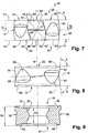
- Each of the insert symmetry points 56 is formed at the intersection of a first reference line L1 with a second reference line L2, as seen in Fig. 7.
- Fig. 7 being a first side view of the cutting insert 18 that is perpendicular to the first or the second secondary cutting edges 44, 50.
- the main cutting edges 32, 34 are identical to each other
- the secondary cutting edges 44, 50 are identical to each other
- both end surfaces 28, namely, the upper surface 22 and the lower surface 24 are identical to each other. Therefore, for numbering the cutting edges of the lower surface 24, an arbitrary decision was made to rotate the cutting insert 18 180° around the symmetry axis S. In this position, the cutting edges which were previously located in the upper surface 22 are now located in the lower surface 24 and a prime sign was added to their number. Thus, for example, the corresponding cutting edge of the first main cutting edge 32 is marked 32' , and so on.
- the first reference line L1 connects the leading end 36 of a first main cutting edge 32 of a given end surface 28 with the leading end 36' of a first main cutting edge 32' of the opposite end surface 28.
- the second reference line L2 connects the trailing end 42 of a second main cutting edge 34 of a given end surface 28 with the trailing end 42' of a second main cutting edge 34' of the opposite end surface 28.
- the peripheral surface 26 comprises a first pair of side abutment surfaces 58, a second pair of side abutment surfaces 60, a third pair of side abutment surfaces 62 and a fourth pair of side abutment surfaces 64.
- each pair of the side abutment surfaces 58, 60, 62, 64 has 180° rotational symmetry around the through bore axis B.
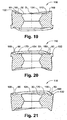
- FIG. 9 is a view of a cross-section taken in a first section plane P3.
- the first section plane P3 contains the through bore axis B and is obliquely disposed, as seen in Fig. 4 being an end view of the cutting insert 18, with respect to a symmetry plane SP containing the through bore axis B and the symmetry axis S.
- FIG. 10 is a view of a cross-section taken in a second section plane P4.
- the second section plane P4 contains the through bore axis B and is obliquely disposed, as seen in Fig. 4 , with respect to the symmetry plane SP and with respect to the first section plane P3.
- the first section plane P3 forms with the second section plane P4 a plane angle ⁇ of 80°.
- the plane angle ⁇ between the first section plane P3 and the second section plane P4 may be seen also in Fig. 6 , where the first section plane P3 is perpendicular to the first pair of side abutment surfaces 58 and the second section plane P4 is perpendicular to the second pair of side abutment surfaces 60.
- each side abutment surface of the third pair of side abutment surfaces 62 converges towards each other in a direction toward the upper surface 22.
- Each side abutment surface of the fourth pair of side abutment surfaces 64 converges towards each other in a direction toward the lower surface 24.
- the third pair of side abutment surfaces 62 has 180° rotational symmetry with the fourth pair of side abutment surfaces 64 around the symmetry axis S.
- the peripheral surface 26 forms with the first reference plane P1 and with the second reference plane P2 an obtuse first internal included angle ⁇ .
- Fig. 7 being a first side view of the cutting insert 18, is viewed from a direction perpendicular to a secondary cutting edge 44 .
- Fig. 8 is a second side view of the cutting insert 18 taken in a direction perpendicular to the symmetry plane SP.
- the direction perpendicular to the symmetry plane SP is represented by an imaginary plane N.
- the direction of the second side view of the cutting insert 18 is perpendicular to the direction of the first side view of the cutting insert 18.
- the peripheral surface 26 forms with the first reference plane P1 and with the second reference plane P2 an acute second internal included angle ⁇ :
- the first cutting edge axis A1 and the second cutting edge axis A2 are located at opposite sides of the symmetry plane SP.
- the first cutting edge axis A1 is distanced a first axis distance D5 from the symmetry plane SP and the second cutting edge axis A2 is distanced a second axis distance D6 from the symmetry plane SP.
- the first axis distance D5 is equal to the second axis distance D6.
- the first cutting edge axis A1 and the second cutting edge axis A2 may be located at opposite sides of the imaginary plane N.
- the first cutting edge axis A1 is distanced a third axis distance D7 from the imaginary plane N and the second cutting edge axis A2 is distanced a fourth axis distance D8 from the imaginary plane N.
- the third axis distance D7 is equal to the fourth axis distance D8.
- the first and second main cutting edges 32, 34 of a given end surface 28 and their associated first and second secondary cutting edges 44, 50 form a continuously extending cutting edge 66 that is associated with a rake surface 68.
- the rake surface 68 extends continuously along the entire length of the cutting edge 66 .
- the rake surface 68 extends inwardly from the cutting edge 66 toward the through bore axis B, and rearwardly toward the other end surface 28.
- the upper surface 22 of the cutting insert 18 is provided with a planar upper central abutment surface 70 that extends inwardly from the associated rake surface 68 toward the through bore 30.
- the lower surface 24 is provided with a planar lower central abutment surface 72 that extends inwardly from the associated rake surface 68 toward the through bore 30.
- the upper central abutment surface 70 is distanced a third distance D3 from the lower central abutment surface 72
- the first reference plane P1 is distanced a fourth distance D4 from the second reference plane P2
- the third distance D3 is smaller than the fourth distance D4.
- Each insert pocket 14 comprise a pocket tangential abutment surface 74.
- the pocket tangential abutment surface 74 may be planar, and it may be formed as a single surface, as shown in Fig. 11 , or be divided into several surfaces. If the pocket tangential abutment surface is divided into several surfaces, the several surfaces may be separated by relief grooves.
- a threaded bore 76 extends tangentially rearwardly from the pocket tangential abutment surface 74.
- the insert pocket 14 further comprises pocket side walls 78 that extend upwardly from the pocket tangential abutment surface 74. Two of the pocket side walls 78 form pocket abutment surfaces. In one embodiment, the pocket abutment surfaces are spaced apart by a pocket side wall 78 that does not form a pocket abutment surface.
- the pocket abutment surfaces comprise a first pocket abutment surface 80 and a second pocket abutment surface 82.
- the first pocket abutment surface 80 forms an acute first pocket internal angle ⁇ with the pocket tangential abutment surface 74
- the second pocket abutment surface 82 forms an acute second pocket internal angle ⁇ with the pocket tangential abutment surface 74.
- the insert lower central abutment surface 72 abuts the pocket tangential abutment surface 74, one abutment surface of the insert first pair of side abutment surfaces 58 abuts the first pocket abutment surface 80, one abutment surface of the insert third pair of side abutment surfaces 62 abuts the second pocket abutment surface 82, and, the clamping screw 20 passes through the through bore 30 of the cutting insert 18 and threadingly engages the threaded bore 76 of the insert pocket 14.
- the seating of the insert first 58 and third 62 operative side abutment surfaces against the first and second pocket abutment surfaces 80, 82 provides a firm clamping of the cutting insert 18 in a dove-tail manner thus better securing the cutting insert 18 within the insert pocket 14.
- the insert pocket 14 is provided with a pocket abutment relief surface 84 that is located above the second pocket abutment surface 82 and away from the pocket tangential abutment surface 74. In a retained position of the cutting insert 18, the pocket abutment relief surface 84 is relieved from the adjacent abutment surface of the insert fourth pair of side abutment surfaces 64.
- the insert pocket 14 is further provided with a pocket relief channel 86.
- the pocket relief channel 86 is located between the pocket side walls 78 and the pocket tangential abutment surface 74.
- the pocket relief channel 86 provides adequate clearance to the cutting edge 66 associated with the lower central abutment surface 72 of the cutting insert 18 that abuts the pocket tangential abutment surface 74.
- the first pocket abutment surface 80 forms with the second pocket abutment surface 82 an acute pocket angle ⁇ in order to adequately support the side abutment surfaces of the cutting insert 18.
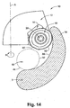
- Fig. 14 shows a top view of the cutting insert 18 when retained within an insert pocket 14 and machining a workpiece W. For sake of clarity, only a part of the tool body 12 is shown. As shown, the active main cutting edge 32 that may be round along a relatively large arc enables the cutting tool 10 to effectively machine, for example, internal profiles of turbine blades T along the entire internal surface 88 of the blade T.
- the cutting insert 18 drawn in solid lines shows the location of the cutting insert when beginning to machine the internal surface 88 of the turbine blade T.
- the cutting insert 18 drawn in dashed lines shows the location of the cutting insert when ending the machining of the internal surface 88 of the turbine blade T .
- the entire active main cutting edge 32 is operative during this machining process. Since the main cutting edge 32 extends along a relatively large arc, it is effective for machining an entire concave internal surface 88 of a turbine blade T.
- the active secondary cutting edge 44 may effectively perform ramp-down operations.
- the cutting insert 18 is capable of performing a variety of cutting operations, and may be four times indexable within an insert pocket 14.
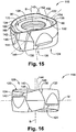
- Figs. 15 to 21 show another embodiment of the cutting insert.
- like parts are designated with like reference numerals with the addition of 100.
- the cutting insert 118 shown in Figs. 15 to 21 has a structure similar to the structure of the cutting insert 18 described above, however, it differs in the shape of its cutting edges.
- the cutting insert 118 comprises, in each end surface 128 thereof, first and second main cutting edges 132, 134 that are connected, through extremities thereof, to first and second secondary cutting edges 144, 150.
- the first main cutting edge 132 has a leading end 136 and a trailing end 138 .
- the second main cutting edge 134 has a leading end 140 and a trailing end 142.
- a first secondary cutting edge 144 merges, at a leading end 146 thereof, with the leading end 136 of the first main cutting edge 132, and, at a trailing end 148 thereof, with the trailing end 142 of the second main cutting edge 134.
- a second secondary cutting edge 150 merges, at a leading end 152 thereof, with the leading end 140 of the second main cutting edge 134, and, at a trailing end 154 thereof, with the trailing end 138 of the first main cutting edge 132.
- the first secondary cutting edge 144 may be identical to the second secondary cutting edge 150.
- the first and second secondary cutting edges 144, 150 are mainly used for performing ramp-down operations and their length and shape are determined according to machining needs.
- the first main cutting edge 132 may be identical to the second main cutting edge 134.
- the leading end 136 of the first main cutting edge 132 is located further from the median plane M than the trailing end 138 of the first main cutting edge.
- the leading end 140 of the second main cutting edge 134 is located further from the median plane M than the trailing end 142 of the second main cutting edge 134.
- Each of the first and second main cutting edges 132, 134 lies on a torus. Furthermore, when the cutting insert is retained in the insert pocket 14 of the cutting tool 10, and the cutting tool is rotated about its axis of rotation A by 360°, each point on an operative main cutting edge, i.e., first main cutting edge 132 or second main cutting edge 134, sweeps out a portion of a torus.
- the first and second main cutting edges 132, 134 and their associated first and second secondary cutting edges 144,150 form a continuously extending cutting edge 166 that is associated with a rake surface 168 that may extend continuously along the entire circumference of an end surface 128.
- the rake surface 168 merges with the upper central abutment surface 170 through an undercut 90 which serves two purposes. First, it enables better control of the chips produced during machining. Second, it enables better distinguishing of the upper central abutment surface 170 with respect to the upper surface 122 of the cutting insert 118, thus assuring satisfactory abutment properties of the upper central abutment surface 170.
- the undercut 90 may vary in size and shape at different cross-sections of the cutting insert 118. Similarly, the same may be applied to the lower surface 124 of the cutting insert 118.
- the height orientation of the main cutting edges 132, 134 with respect to the central abutment surface 170 is such that the cutting edges are higher than the central abutment surface, i.e., the central abutment surface 170 is located closer to the median plane M than the main cutting edges 132, 134.
- the main cutting edges 132, 134, or at least a portion thereof may be located closer to the median plane M than the central abutment surface 170.
- the construction of the cutting insert 118 enables considerable advantages during machining, as can be appreciated by a person skilled in the art.
- the highly positive rake of the main cutting edges provides the operative main cutting edge of the cutting insert 118, when the cutting insert 118 is mounted in the cutting tool 10 during machining, with a less negative rake angle, compared to the negative rake angle of the cutting insert 18 shown in Fig. 1 that is mounted in a negative axial positioning.
- the less negative axial rake leads to easier cutting, better chip removal, lower cutting forces, and, lower power consumption.
- This construction of the cutting insert 118 may be used when it is required to machine relatively high tensile materials and high temperature alloys. A further advantage in this case may be avoiding adhesion of the chips.
- FIG. 22 shows a cutting insert not in accordance with the present invention.
- like parts are designated with like reference numerals with the addition of 200.
- a cutting insert 218 comprises two end surfaces 228 and a peripheral surface 226 extending therebetween.
- One of the end surfaces 228 forms an upper surface 222 similar to the upper surface 122 of the cutting insert 118 described above, and, another end surface forms a lower surface 224 of the cutting insert 218.
- the upper surface 222 comprises a continuously extending peripheral cutting edge 266 associated with a continuously extending rake surface 268.
- the cutting edge 266 comprises two curved cutting edges, namely, a first main cutting edge 232 and a second main cutting edge 234, and, two straight cutting edges, namely, a first secondary cutting edge 244 and a second secondary cutting edge 250 connecting between extremities of the first and second main cutting edges 232, 234 (the first secondary cutting edge 244 is not shown).
- the rake surface 268 if formed considerably larger than the rake surface 168 of the cutting insert 118.
- the rake surface 268 is slanted at a rake slant angle ⁇ with respect to the lower surface 224 of the cutting insert 218.
- the rake slant angle ⁇ is relatively large and is preferably equal to or greater than 25°.
- a rake inner extremity 92 is defined at a region where an innermost extremity of the rake surface 268 merges with a bore peripheral region 94 that surrounds the through bore 30.
- the bore peripheral region 94 merges with the through bore 30 at a bore upper end 96 and it extends generally parallel to the lower surface 224 of the cutting insert 218.
- a first rake length H1 is defined between a given point 98 on the peripheral cutting edge 266 and the rake inner extremity 92, measured in a plane parallel to the lower surface 224.
- a second rake length H2 is defined between the same given point 98 on the peripheral cutting edge 266 and the bore upper end 96, measured in a plane parallel to the lower surface 224.
- a rake extension ratio E is defined as a ratio between the first rake length H1 and the second rake length H2.
- the rake extension ratio E may vary within a preferable range. According to one embodiment, the rake extension ratio E is smaller than 1 and equal to or greater than 0.8.
- the rake surface 268 Since the rake surface 268 is relatively very large, it extends, in an inward direction of the cutting insert 218, almost to the through bore 30. With such a construction, the upper surface 222 lacks a central abutment surface, in contrary to the existence of the central abutment surface 170 in the upper surface 122 of the cutting insert 118.
- the cutting insert 218 lacks a central abutment surface, it cannot be used as a double sided cutting insert. Therefore, the lower surface 224 of the cutting insert 118 lacks cutting edges, and is formed flat in order to serve solely as an abutment surface. Accordingly, the peripheral surface 226 is formed only with the abutment surfaces required for abutment of a single sided cutting insert, namely, the first pair of side abutment surfaces 258, and, the third pair of side abutment surfaces 262 (not shown).
- the cutting insert is not limited to have two main cutting edges on each end surface.
- the cutting insert is provided with three main cutting edges which are connected, at extremities thereof, by three secondary cutting edges.
- the three main cutting edges may be identical.
- the three secondary cutting edges may be identical.
- the cutting insert is provided with four main cutting edges which are connected, at extremities thereof, by four secondary cutting edges.
- the four main cutting edges may be identical.
- the four secondary cutting edges may be identical.
- a cutting insert according to the present invention may be retained by a clamping screw passing through a through bore.
- the cutting insert may have four, six or eight rounded cutting edges, wherein the cutting insert may be indexed four, , six or eight times.
- the cutting edges may extend along a large arc and may extend at an angle larger than 120°.
Landscapes
- Engineering & Computer Science (AREA)
- Mechanical Engineering (AREA)
- Milling Processes (AREA)
- Cutting Tools, Boring Holders, And Turrets (AREA)
Claims (12)
- Schneideinsatz (18, 118) zum Halten in einem rotierenden Schneidwerkzeug (10) mit einer Rotationsachse (A), wobei der Schneideinsatz aufweist:zwei gegenüberliegende Endflächen (28, 128) und eine sich dazwischen erstreckende Umfangsseitenfläche (26), wobei jede Endfläche eine die Endflächen (28, 128) durchlaufende gemeinsame erste Symmetrieachse (B) hat, um die jede Endfläche (28, 128) N-fache Rotationssymmetrie für einen gewissen Wert N hat, wobei N aus der Gruppe von 2, 3 und 4 ausgewählt ist;eine Umfangsschneidkante (66, 166), die am Übergang zwischen jeder Endfläche (28, 128) und der Umfangsseitenfläche (26) gebildet ist, wobei die Umfangskante N gekrümmte Schneidkanten (32, 34; 132, 134) aufweist, die sich mit N geraden Schneidkanten (44, 50; 144, 150), die sich zwischen den gekrümmten Schneidkanten (32, 34; 132, 134) erstrecken, an Extremen davon vereinigen; wobei:sich die gekrümmten Schneidkanten (32, 34; 132, 134) der beiden Endflächen (28, 128) in Endansicht des Schneideinsatzes (18, 118) entlang der ersten Symmetrieachse (B) nicht überdecken; und dadurch gekennzeichnet, dass jede der N gekrümmten Schneidkanten (32, 34; 132, 134) auf einem Torus liegt.
- Schneideinsatz (18, 118) nach Anspruch 1, wobei:sich N Schneidkantenachsen (C), die in einem Mittelabschnitt (35) jeder der N gekrümmten Schneidkanten (32, 34; 132, 134) liegen, parallel zur Symmetrieachse (B) erstrecken undjede der N gekrümmten Schneidkanten (32, 34; 132, 134) einer der Endflächen (28, 128) um ihre zugeordnete Schneidkantenachse (C) relativ zu einer entgegengesetzten gekrümmten Schneidkante (34', 32') der anderen Endfläche mit Blick in Endansicht des Schneideinsatzes (18, 118) entlang der Symmetrieachse (B) gedreht ist.
- Schneideinsatz (18, 118) nach Anspruch 1, wobei:jede wirkende gekrümmte Schneidkante (32, 34; 132, 134) einen Abschnitt eines Torus überstreicht, wenn der Schneideinsatz (18, 118) im rotierenden Schneidwerkzeug (10) gehalten wird und das rotierende Schneidwerkzeug (10) 360° um seine Rotationsachse (A) gedreht wird.
- Schneideinsatz (118) nach Anspruch 1, wobei:ein Extrem (136, 140) jeder gegebenen gekrümmten Schneidkante (132, 134) von einer Medianebene (M) des Schneideinsatzes (118) weiter entfernt als das andere Extrem (138, 142) der vorgegebenen gekrümmten Schneidkante (132, 134) liegt, wobei die Medianebene (M) auf halbem Weg zwischen den Endflächen (128) liegt.
- Schneideinsatz (18) nach Anspruch 1, wobei:die gekrümmten Schneidkanten (32, 34) in Zuordnung zu einer der Endflächen (28) in einer ersten Referenzebene (P1) liegen und die gekrümmten Schneidkanten (32', 34') in Zuordnung zur anderen Endfläche in einer zweiten Referenzebene (P2) liegen,wobei die erste und zweite Referenzebene (P1, P2) parallel zueinander sind und im gleichen Abstand von einer Medianebene (M) des Schneideinsatzes (18) und auf jeder Seite davon liegen und die Medianebene (M) auf halbem Weg zwischen den Endflächen (28) liegt.
- Schneideinsatz (18, 118) nach Anspruch 1, wobei:der Schneideinsatz eine Durchgangsbohrung (30) mit einer eine erste Symmetrieachse bildenden Durchgangsbohrungsachse (B) aufweist, die sich zwischen den beiden Endflächen (28) erstreckt; unddie Umfangsfläche (26) ein erstes (58), zweites (60), drittes (62) und viertes (64) Paar Seitenanlageflächen aufweist und jedes Paar Seitenanlageflächen 180°-Rotationssymmetrie um die Durchgangsbohrungsachse (B) hat.
- Schneideinsatz (18, 118) nach Anspruch 1, wobei:die beiden Endflächen (28, 128) identisch sind.
- Schneideinsatz (18, 118) nach Anspruch 7, wobei:sich ein Hauptabschnitt (MP11, MP12) jeder der gekrümmten Schneidkanten (32, 34; 132, 134) entlang eines Winkels von mindestens 120° mit Blick entlang der ersten Symmetrieachse (B) erstreckt.
- Schneideinsatz (18, 118) nach Anspruch 1, wobei:eine erste Endfläche, die eine Oberseite (22, 122) bildet, eine erste Referenzebene (P1) definiert, eine zweite Endfläche, die eine Unterseite (24, 124) bildet, eine zweite Referenzebene (P2) parallel zur ersten Referenzebene (P1) definiert;sich eine Durchgangsbohrung (30) mit einer die erste Symmetrieachse bildenden Durchgangsbohrungsachse (B) zwischen der Oberseite (22, 122) und der Unterseite (24, 124) erstreckt;die gekrümmten Schneidkanten (32, 34; 132, 134) eine erste Hauptschneidkante (32, 132) und eine zweite Hauptschneidkante (34, 134) aufweisen;in Endansicht des Schneideinsatzes (18, 118) die erste Hauptschneidkante (32, 132) einen ersten Krümmungsradius (R1) im Hinblick auf eine erste Schneidkantenachse (A1) hat und die zweite Hauptschneidkante (34, 134) einen zweiten Krümmungsradius (R2) im Hinblick auf eine zweite Schneidkantenachse (A2) hat,die erste Schneidkantenachse (A1) und die zweite Schneidkantenachse (A2) parallel zur Durchgangsbohrungsachse (B) sind und auf Gegenseiten davon liegen;die erste Schneidkantenachse (A1) in einem ersten Abstand (D1) von der zweiten Hauptschneidkante (34, 134) liegt, die Durchgangsbohrungsachse (B) in einem zweiten Abstand (D2) von der zweiten Hauptschneidkante (34, 134) liegt und der erste Abstand (D1) kleiner als der zweite Abstand (D2) ist.
- Schneideinsatz (18, 118) nach Anspruch 9, wobei der Schneideinsatz (18, 118) 180°-Rotationssymmetrie um eine zweite Symmetrieachse (S) hat, die zweite Symmetrieachse (S) auf einer Medianebene (M) zwischen der ersten und der zweiten Referenzebene (P1, P2) liegt und die Umfangsfläche (26) an zwei Einsatzsymmetriepunkten (56) schneidet;
jeder der Einsatzsymmetriepunkte (56) am Schnitt einer ersten Referenzlinie (L1) mit einer zweiten Referenzlinie (L2) mit Blick in einer ersten Seitenansicht des
Schneideinsatzes (18, 118) gebildet ist, die senkrecht zu einer gegebenen Sekundärschneidkante ist;
die erste Referenzlinie (L1) das vorlaufende Ende (36, 136) einer ersten Hauptschneidkante (32, 132) einer gegebenen Endfläche (28, 128) mit dem vorlaufenden Ende (36, 136) einer ersten Hauptschneidkante (32, 132) einer entgegengesetzten Endfläche (28, 128) verbindet; und
die zweite Referenzlinie (L2) das nachlaufende Ende (42, 142) einer zweiten Hauptschneidkante (34, 134) einer vorgegebenen Endfläche (28) mit dem nachlaufenden Ende (42, 142) einer zweiten Hauptschneidkante (34, 134) einer entgegengesetzten Endfläche (28) verbindet. - Schneideinsatz (18, 118) nach Anspruch 10, wobei die erste Schneidkantenachse (A1) und die zweite Schneidkantenachse (A2) auf Gegenseiten einer gedachten Ebene (N) liegen, die senkrecht zu einer Symmetrieebene (SP) ist, die die erste Symmetrieachse (B) und die zweite Symmetrieachse (S) enthält.
- Schneidwerkzeug (10), das eine Längsrotationsachse (A) hat und aufweist:einen Werkzeugkörper (12) mit mindestens einer Einsatztasche (14), die in einem vorderen Ende (16) des Werkzeugkörpers gebildet ist, und einen Schneideinsatz (18, 118) nach Anspruch 1, der in der mindestens einen Einsatztasche gehalten wird, wobei die mindestens eine Einsatztasche aufweist:eine tangentiale Taschenanlagefläche (74);eine Gewindebohrung (76), die sich von der tangentialen Taschenanlagefläche tangential nach hinten erstreckt;Taschenseitenwände (78), die sich von der tangentialen Taschenanlagefläche (74) nach oben erstrecken und die eine erste Taschenanlagefläche (80), die einen spitzen ersten Tascheninnenwinkel (γ) mit der tangentialen Taschenanlagefläche (74) bildet,und eine zweite Taschenanlagefläche (82), die einen spitzen zweiten Tascheninnenwinkel (δ) mit der tangentialen Taschenanlagefläche (74) bildet, aufweisen, wobei die erste und zweite Taschenanlagefläche (80, 82) voneinander beabstandet sind;wobei der Schneideinsatz (18, 118) aufweist:ein erstes (58), zweites (60), drittes (62) und viertes (64) Paar Seitenanlageflächen,wobei jedes Paar Seitenanlageflächen 180°-Rotationssymmetrie um die Durchgangsbohrungsachse (B) hat,das erste Paar Seitenanlageflächen (58) in einer Richtung zur Oberseite (22, 122) zueinander konvergiert,das zweite Paar Seitenanlageflächen (60) in einer Richtung zur Unterseite (24, 124) zueinander konvergiert,das dritte Paar Seitenanlageflächen (62) in einer Richtung zur Oberseite (22, 122) zueinander konvergiert,das vierte Paar Seitenanlageflächen (64) in einer Richtung zur Unterseite (24, 124) zueinander konvergiert,das dritte Paar 180°-Rotationssymmetrie mit dem vierten Paar (64) um eine zweite Symmetrieachse (S) hat, die zwischen dem dritten Paar (62) und dem vierten Paar (64) verläuft,die Oberseite (22, 122) eine erste Referenzebene (P1) definiert und die Unterseite eine zweite Referenzebene (P2) definiert, wobei die erste und zweite Referenzebene (P1, P2) parallel zu einer Medianebene (M) sind, die auf halbem Weg zwischen der Oberseite (22, 122) und der Unterseite (24, 124) liegt,die Umfangsfläche (26) mit der ersten Referenzebene (P1) und mit der zweiten Referenzebene (P2) einen stumpfen ersten eingeschlossenen Innenwinkel (α) mit Blick in einer ersten Seitenansicht des Schneideinsatzes (18, 118) bildet, die senkrecht zu einer gegebenen Sekundärschneidkante ist,die Umfangsfläche (26) mit der ersten Referenzebene (P1) und mit der zweiten Referenzebene (P2) einen spitzen zweiten eingeschlossenen Innenwinkel (β) mit Blick in einer zweiten Seitenansicht des Schneideinsatzes (18, 118) bildet, die senkrecht zur ersten Seitenansicht ist,die Oberseite (22, 122) mit einer ebenen oberen Mittelanlagefläche (70, 170) versehen ist, die eine obere tangentiale Einsatzanlagefläche bildet, die sich von einer zugeordneten Spanfläche (68, 168) zur Durchgangsbohrung (30) nach innen erstreckt;die Unterseite (24, 124) mit einer ebenen unteren Mittelanlagefläche (72) versehen ist, die eine untere tangentiale Einsatzanlagefläche bildet, die sich von der zugeordneten Spanfläche (68, 168) zur Durchgangsbohrung (30) nach innen erstreckt;wobei:in einer gehaltenen Position des Schneideinsatzes (18, 118) die untere tangentiale Einsatzanlagefläche (72) an der tangentialen Taschenanlagefläche (74) anliegt, eine Anlagefläche des ersten Paars Seitenanlageflächen (58) des Einsatzes an der ersten Taschenanlagefläche (80) anliegt, eine Anlagefläche des dritten Paars Seitenanlageflächen (62) des Einsatzes an der zweiten Taschenanlagefläche (82) anliegt und eine Klemmschraube (20) die Durchgangsbohrung (30) des Schneideinsatzes durchläuft und einen Gewindeeingriff mit der Gewindebohrung (76) der Einsatztasche herstellt.
Priority Applications (2)
| Application Number | Priority Date | Filing Date | Title |
|---|---|---|---|
| EP14199208.1A EP2857132B1 (de) | 2008-08-31 | 2009-08-19 | Doppelseitiger schneideinsatz |
| EP16181825.7A EP3112069A1 (de) | 2008-08-31 | 2009-08-19 | Doppelseitiger schneideinsatz |
Applications Claiming Priority (2)
| Application Number | Priority Date | Filing Date | Title |
|---|---|---|---|
| IL19377908 | 2008-08-31 | ||
| PCT/IL2009/000814 WO2010023659A1 (en) | 2008-08-31 | 2009-08-19 | Cutting tool and round double sided cutting insert therefor |
Related Child Applications (4)
| Application Number | Title | Priority Date | Filing Date |
|---|---|---|---|
| EP16181825.7A Division EP3112069A1 (de) | 2008-08-31 | 2009-08-19 | Doppelseitiger schneideinsatz |
| EP16181825.7A Division-Into EP3112069A1 (de) | 2008-08-31 | 2009-08-19 | Doppelseitiger schneideinsatz |
| EP14199208.1A Division EP2857132B1 (de) | 2008-08-31 | 2009-08-19 | Doppelseitiger schneideinsatz |
| EP14199208.1A Division-Into EP2857132B1 (de) | 2008-08-31 | 2009-08-19 | Doppelseitiger schneideinsatz |
Publications (2)
| Publication Number | Publication Date |
|---|---|
| EP2323794A1 EP2323794A1 (de) | 2011-05-25 |
| EP2323794B1 true EP2323794B1 (de) | 2017-04-19 |
Family
ID=41346094
Family Applications (3)
| Application Number | Title | Priority Date | Filing Date |
|---|---|---|---|
| EP14199208.1A Active EP2857132B1 (de) | 2008-08-31 | 2009-08-19 | Doppelseitiger schneideinsatz |
| EP09787542.1A Active EP2323794B1 (de) | 2008-08-31 | 2009-08-19 | Schneidwerkzeug und runder doppelseitiger schneideinsatz dafür |
| EP16181825.7A Withdrawn EP3112069A1 (de) | 2008-08-31 | 2009-08-19 | Doppelseitiger schneideinsatz |
Family Applications Before (1)
| Application Number | Title | Priority Date | Filing Date |
|---|---|---|---|
| EP14199208.1A Active EP2857132B1 (de) | 2008-08-31 | 2009-08-19 | Doppelseitiger schneideinsatz |
Family Applications After (1)
| Application Number | Title | Priority Date | Filing Date |
|---|---|---|---|
| EP16181825.7A Withdrawn EP3112069A1 (de) | 2008-08-31 | 2009-08-19 | Doppelseitiger schneideinsatz |
Country Status (15)
| Country | Link |
|---|---|
| US (2) | US8206066B2 (de) |
| EP (3) | EP2857132B1 (de) |
| JP (2) | JP5543460B2 (de) |
| KR (2) | KR101509417B1 (de) |
| CN (2) | CN103737093B (de) |
| BR (1) | BRPI0916852B8 (de) |
| CA (1) | CA2731559C (de) |
| DE (1) | DE202008018646U1 (de) |
| ES (2) | ES2631506T3 (de) |
| IL (1) | IL210604A (de) |
| PL (2) | PL2323794T3 (de) |
| PT (2) | PT2857132T (de) |
| RU (1) | RU2505382C2 (de) |
| TW (1) | TW201010810A (de) |
| WO (1) | WO2010023659A1 (de) |
Families Citing this family (47)
| Publication number | Priority date | Publication date | Assignee | Title |
|---|---|---|---|---|
| SE533269C2 (sv) * | 2008-12-17 | 2010-08-03 | Sandvik Intellectual Property | Dubbelsidigt, indexerbart planfrässkär |
| SE0900286A1 (sv) * | 2009-03-06 | 2010-07-27 | Seco Tools Ab | Skär med urtagen skärstödjande yta och skärverktyg |
| SE534506C2 (sv) * | 2009-04-30 | 2011-09-13 | Seco Tools Ab | Skärverktyg och en skärhållare för ett skärverktyg |
| KR101103216B1 (ko) * | 2009-05-19 | 2012-01-05 | 대구텍 유한회사 | 원형 형상을 갖는 양면형 절삭 삽입체 및 이를 사용하는 절삭 공구 |
| EP2546012A4 (de) * | 2010-03-10 | 2013-08-07 | Tungaloy Corp | Schneideeinsatz und schneidewerkzeug |
| EP2623240B1 (de) * | 2010-09-30 | 2017-11-15 | Tungaloy Corporation | Schneidewerkzeug mit austauschbarer klingenkante |
| EP2455172B1 (de) * | 2010-11-19 | 2013-01-16 | SECO TOOLS AB (publ) | Schneideinsatz mit sich veränderndem Keil- oder Freiwinkel und Werkzeughalter mit einem solchen Schneideinsatz |
| DE102010063611A1 (de) * | 2010-12-20 | 2012-06-21 | Walter Ag | Schneideinsatz mit strukturierten Freiflächen |
| AT12527U1 (de) * | 2011-02-24 | 2012-07-15 | Ceratizit Austria Gmbh | Schneideinsatz zur spanabhebenden bearbeitung |
| CN103619519B (zh) * | 2011-06-30 | 2016-09-07 | 京瓷株式会社 | 切削镶刀及切削工具以及使用该切削工具的切削加工物的制造方法 |
| IL214781A0 (en) * | 2011-08-22 | 2011-10-31 | Iscar Ltd | Cutting tool and cutting insert therefor |
| AT12630U1 (de) | 2011-08-26 | 2012-09-15 | Ceratizit Austria Gmbh | Doppelseitiger schneideinsatz zum fräsen |
| AT12672U1 (de) * | 2011-09-15 | 2012-09-15 | Ceratizit Luxembourg S Ar L | Satz von schneideinsätzen und fräswerkzeughalter |
| AT12669U1 (de) * | 2011-11-16 | 2012-09-15 | Ceratizit Luxembourg S Ar L | Cutting insert |
| US9475134B2 (en) | 2011-12-19 | 2016-10-25 | Iscar, Ltd. | Cutting insert and cutting tool |
| EP2614907B1 (de) * | 2012-01-13 | 2016-11-30 | Seco Tools Ab | Schneideinsatz mit abgewinkelter Stützfläche, Werkzeughalter mit abgewinkelter Stützfläche und Schneideinsatz |
| SE536343C2 (sv) * | 2012-01-16 | 2013-09-03 | Sandvik Intellectual Property | Fräsverktyg jämte dubbelsidigt indexerbart frässkär |
| EP2818269B1 (de) * | 2012-02-20 | 2016-05-25 | Tungaloy Corporation | Schneideinsatz und schneidwerkzeug mit auswechselbarer schneidkante |
| WO2013180161A1 (ja) * | 2012-05-30 | 2013-12-05 | 京セラ株式会社 | 切削インサート、切削工具および被削加工物の製造方法 |
| WO2014034614A1 (ja) * | 2012-08-30 | 2014-03-06 | 京セラ株式会社 | 切削インサート、切削工具および切削加工物の製造方法 |
| WO2014088008A1 (ja) * | 2012-12-05 | 2014-06-12 | 株式会社タンガロイ | 切削工具用ボデーおよび該ボデーを適用した切削工具 |
| US9649700B2 (en) * | 2013-03-18 | 2017-05-16 | Kennametal Inc. | Method for manufacturing an insert-receiving pocket wall with a compound radius |
| US9339873B2 (en) * | 2013-12-11 | 2016-05-17 | Iscar, Ltd. | Cutting insert having a dovetail anti-slip arrangement |
| KR101524540B1 (ko) * | 2013-12-30 | 2015-06-01 | 한국야금 주식회사 | 인서트 및 이를 체결하는 공구 홀더 |
| JP5963034B2 (ja) * | 2014-04-15 | 2016-08-03 | 株式会社タンガロイ | 切削インサート、工具ボデー及び刃先交換式回転切削工具 |
| WO2016054647A1 (en) * | 2014-10-03 | 2016-04-07 | Costa Larry J | Method and apparatus for encoding data on a work piece |
| CN107000082B (zh) * | 2015-03-05 | 2020-03-13 | 株式会社泰珂洛 | 切削刀片以及刀尖更换式旋转切削刀具 |
| US10350689B2 (en) * | 2015-06-29 | 2019-07-16 | Mitsubishi Hitachi Tool Engineering, Ltd. | Double-sided circular cutting insert and indexable rotary cutting tool |
| JP6048632B1 (ja) * | 2015-06-29 | 2016-12-21 | 三菱日立ツール株式会社 | 両面型の円形切削インサート及び刃先交換式回転切削工具 |
| KR101717279B1 (ko) * | 2015-08-28 | 2017-03-16 | 한국야금 주식회사 | 절삭 인서트 및 이를 장착하는 절삭 공구 |
| CN106552975B (zh) | 2015-09-28 | 2019-01-01 | 通用电气公司 | 加工工具和加工系统 |
| US20170120351A1 (en) | 2015-11-03 | 2017-05-04 | Kennametal Inc. | Double-sided cutting inserts with positive clearance face geometry |
| CN105269058A (zh) * | 2015-11-13 | 2016-01-27 | 株洲钻石切削刀具股份有限公司 | 一种装有圆形刀片的切削刀具 |
| US10183333B2 (en) * | 2016-02-03 | 2019-01-22 | Iscar, Ltd. | Circular cutting insert having non-circular peripheral edge |
| EP3263257A1 (de) * | 2016-06-30 | 2018-01-03 | Ceratizit Luxembourg Sàrl | Fräswerkzeug |
| US10005141B2 (en) * | 2016-08-04 | 2018-06-26 | Iscar, Ltd. | Tool holder having insert receiving pocket with stress relief surfaces |
| EP3351329B1 (de) * | 2017-01-18 | 2023-08-02 | Sandvik Intellectual Property AB | Indexierbarer schneideeinsatz für ein fräswerkzeug |
| US10632548B2 (en) * | 2017-11-20 | 2020-04-28 | Iscar, Ltd. | Triangular-shaped indexable cutting insert having recessed side surfaces and rotary cutting tool |
| CN107803523A (zh) * | 2017-12-06 | 2018-03-16 | 成都工具研究所有限公司 | 可转位环形刀片 |
| US10646927B2 (en) * | 2018-02-19 | 2020-05-12 | Iscar, Ltd. | Round double-sided cutting insert having a peripheral surface provided with protruding indexing latches, insert holder therefor and cutting tool |
| KR102115293B1 (ko) * | 2018-12-21 | 2020-05-26 | 한국야금 주식회사 | 절삭인서트 및 이를 장착한 절삭공구 |
| EP3689522B1 (de) * | 2019-01-31 | 2023-08-02 | AB Sandvik Coromant | Runder schneideinsatz für ein fräswerkzeug |
| AT16933U1 (de) * | 2019-07-11 | 2020-12-15 | Ceratizit Austria Gmbh | Doppelseitiger Schneideinsatz zum Fräsen |
| KR102253026B1 (ko) * | 2019-10-28 | 2021-05-17 | 한국야금 주식회사 | 절삭 인서트 및 이를 장착한 절삭공구 |
| JP7480291B2 (ja) | 2020-06-01 | 2024-05-09 | 京セラ株式会社 | 切削インサート、切削工具及び切削加工物の製造方法 |
| JP7012948B1 (ja) * | 2021-03-10 | 2022-01-31 | 株式会社タンガロイ | 刃先交換式切削工具の工具本体 |
| JP2023077654A (ja) * | 2021-11-25 | 2023-06-06 | 三菱マテリアル株式会社 | 切削インサート及び切削工具 |
Family Cites Families (35)
| Publication number | Priority date | Publication date | Assignee | Title |
|---|---|---|---|---|
| US3289271A (en) * | 1964-10-13 | 1966-12-06 | Willeys Carbide Tool Co | Indexable cutting inserts |
| US3541655A (en) * | 1967-12-29 | 1970-11-24 | Carmet Co | Indexable and reversible cutting inserts |
| US3762005A (en) * | 1970-08-28 | 1973-10-02 | Ingersoll Milling Machine Co | Indexable cutting insert |
| JPS5112154B2 (de) * | 1972-02-17 | 1976-04-16 | ||
| SE382769B (sv) * | 1974-05-24 | 1976-02-16 | Seco Tools Ab | Vendsker for fresverktyg |
| US4074949A (en) * | 1975-09-19 | 1978-02-21 | Robert Zapp, Werkzeug-Und Maschinenfabrik Gmbh | Cutting tool |
| SU835667A1 (ru) * | 1977-03-28 | 1981-06-07 | Всесоюзный Научно-Исследовательскийинструментальный Институт | Концева фреза |
| US4175896A (en) | 1977-07-25 | 1979-11-27 | Toshiba Tungaloy Co., Ltd. | Ball endmill |
| US4297058A (en) * | 1980-06-30 | 1981-10-27 | Kennametal Inc. | Indexable cutting insert |
| FR2495977A1 (fr) | 1980-12-12 | 1982-06-18 | Feldmuehle Prod Tech France | Procede de realisation d'aretes de coupe et plaquettes ou autres materiaux de coupe montrant ces nouvelles aretes |
| SE452271B (sv) * | 1982-04-01 | 1987-11-23 | Sandvik Ab | Sker och verktyg for spanskerande bearbetning |
| JPS60103610U (ja) * | 1983-12-17 | 1985-07-15 | 日本特殊陶業株式会社 | スロ−アウエイチツプ |
| JPH0115456Y2 (de) * | 1984-09-27 | 1989-05-09 | ||
| SU1445871A1 (ru) * | 1986-12-10 | 1988-12-23 | Предприятие П/Я Р-6491 | Сборный инструмент |
| DE3724006A1 (de) | 1987-07-21 | 1989-02-02 | Feldmuehle Ag | Kombifraeser |
| RU2011483C1 (ru) * | 1992-02-07 | 1994-04-30 | Борис Валентинович Барбышев | Режущий инструмент |
| EP0574376A1 (de) | 1992-06-12 | 1993-12-15 | BÖHLERIT G.m.b.H. & Co. KG | Schneideinsatz für ein spanabhebendes Metallbearbeitungswerkzeug sowie mit diesem ausgerüstetes Bohrwerkzeug |
| IL108115A (en) * | 1993-12-21 | 1997-02-18 | Iscar Ltd | Chip cutting tool |
| JPH10263916A (ja) * | 1997-03-28 | 1998-10-06 | Mitsubishi Materials Corp | スローアウェイチップ |
| JP4315480B2 (ja) | 1997-12-16 | 2009-08-19 | 大昭和精機株式会社 | スローアウェイチップ |
| TW480198B (en) * | 1999-02-22 | 2002-03-21 | Iscar Ltd | Cutting tool assembly and cutting insert therefor |
| IL132261A (en) * | 1999-10-07 | 2003-09-17 | Iscar Ltd | Cutting tool assembly and cutting insert therefor |
| DE20020271U1 (de) | 2000-11-29 | 2002-01-10 | Pokolm Franz Josef | Fräskopf |
| IL144154A0 (en) * | 2001-07-05 | 2002-05-23 | Iscar Ltd | Cutting tool and cutting insert therefor |
| SE525829C2 (sv) * | 2002-06-26 | 2005-05-10 | Seco Tools Ab | Dubbelsidigt vändskär med bomberad biskäregg samt tillverkningsmetod för skäret |
| IL153093A0 (en) * | 2002-11-26 | 2003-06-24 | Iscar Ltd | Cutting insert and cutting tool |
| MXPA05005862A (es) * | 2002-12-04 | 2005-08-29 | Iscar Ltd | Inserto de corte tangencial y fresa. |
| US7094007B2 (en) * | 2002-12-04 | 2006-08-22 | Iscar Ltd. | Tangential cutting insert and milling cutter |
| US7722297B2 (en) | 2003-04-15 | 2010-05-25 | Tdy Industries, Inc. | Antirotation tool holder and cutting insert |
| DE10361450A1 (de) * | 2003-12-23 | 2005-07-28 | EMUGE-Werk Richard Glimpel GmbH & Co. KG Fabrik für Präzisionswerkzeuge | Schneidelement und Werkzeug mit wenigstens einem Schneidelement |
| IL169491A (en) * | 2005-06-30 | 2009-06-15 | Carol Smilovici | Cutting insert |
| DE102005043842B4 (de) * | 2005-09-13 | 2008-09-11 | Franken GmbH + Co KG Fabrik für Präzisionswerkzeuge | Kugel- oder Torusfräser |
| SE530025C2 (sv) * | 2006-06-21 | 2008-02-12 | Seco Tools Ab | Vändbart frässkär och verktyg med trigonformat tangentiellt monterat skär |
| JP2008018515A (ja) * | 2006-07-14 | 2008-01-31 | Mitsubishi Materials Corp | 切削インサート及び切削工具 |
| US7976250B2 (en) * | 2009-02-12 | 2011-07-12 | Tdy Industries, Inc. | Double-sided cutting inserts for high feed milling |
-
2008
- 2008-08-19 DE DE202008018646.3U patent/DE202008018646U1/de not_active Expired - Lifetime
- 2008-09-15 TW TW097135375A patent/TW201010810A/zh unknown
-
2009
- 2009-07-23 US US12/507,843 patent/US8206066B2/en not_active Ceased
- 2009-08-19 PT PT141992081T patent/PT2857132T/pt unknown
- 2009-08-19 ES ES09787542.1T patent/ES2631506T3/es active Active
- 2009-08-19 ES ES14199208.1T patent/ES2586117T3/es active Active
- 2009-08-19 JP JP2011524516A patent/JP5543460B2/ja active Active
- 2009-08-19 CN CN201410032386.4A patent/CN103737093B/zh active Active
- 2009-08-19 BR BRPI0916852A patent/BRPI0916852B8/pt active IP Right Grant
- 2009-08-19 KR KR1020147034369A patent/KR101509417B1/ko active IP Right Grant
- 2009-08-19 PL PL09787542T patent/PL2323794T3/pl unknown
- 2009-08-19 CA CA2731559A patent/CA2731559C/en active Active
- 2009-08-19 EP EP14199208.1A patent/EP2857132B1/de active Active
- 2009-08-19 KR KR1020117004403A patent/KR101553430B1/ko active IP Right Grant
- 2009-08-19 EP EP09787542.1A patent/EP2323794B1/de active Active
- 2009-08-19 EP EP16181825.7A patent/EP3112069A1/de not_active Withdrawn
- 2009-08-19 CN CN200980133638.XA patent/CN102131606B/zh active Active
- 2009-08-19 PT PT97875421T patent/PT2323794T/pt unknown
- 2009-08-19 RU RU2011112284/02A patent/RU2505382C2/ru active
- 2009-08-19 PL PL14199208.1T patent/PL2857132T3/pl unknown
- 2009-08-19 WO PCT/IL2009/000814 patent/WO2010023659A1/en active Application Filing
-
2011
- 2011-01-13 IL IL210604A patent/IL210604A/en active IP Right Grant
-
2014
- 2014-05-08 JP JP2014096971A patent/JP5857088B2/ja active Active
- 2014-06-16 US US14/305,687 patent/USRE45845E1/en active Active
Non-Patent Citations (1)
| Title |
|---|
| None * |
Also Published As
Similar Documents
| Publication | Publication Date | Title |
|---|---|---|
| EP2323794B1 (de) | Schneidwerkzeug und runder doppelseitiger schneideinsatz dafür | |
| US7241082B2 (en) | Double-sided cutting insert and milling cutter | |
| EP1791671B1 (de) | Fräswerkzeug, schneideinsatz für ein fräswerkzeug sowie festes fräswerkzeug | |
| EP2576113B1 (de) | Fräswerkzeug und schneideeinsatz | |
| EP3266547B1 (de) | Schneideinsatz und schneidwerkzeug mit ersetzbarer schneidkante | |
| JP6675416B2 (ja) | 切削インサート及びフライス工具 | |
| EP3338931B1 (de) | Schneideeinsatz und schneidewerkzeug | |
| US8992134B2 (en) | Cutting insert and cutting tool | |
| CN214053814U (zh) | 一种立式安装刀片的螺旋铣削刀具 | |
| JP2019093497A (ja) | 切削インサート及び刃先交換式回転切削工具 | |
| JPH10118824A (ja) | たて型チップおよびそれを備えたフライス | |
| CN109277618B (zh) | 一种用于大圆弧直纹面加工的数控刀具 | |
| BR122019004666B1 (pt) | Inserto de corte de lado duplo |
Legal Events
| Date | Code | Title | Description |
|---|---|---|---|
| PUAI | Public reference made under article 153(3) epc to a published international application that has entered the european phase |
Free format text: ORIGINAL CODE: 0009012 |
|
| 17P | Request for examination filed |
Effective date: 20110308 |
|
| AK | Designated contracting states |
Kind code of ref document: A1 Designated state(s): AT BE BG CH CY CZ DE DK EE ES FI FR GB GR HR HU IE IS IT LI LT LU LV MC MK MT NL NO PL PT RO SE SI SK SM TR |
|
| AX | Request for extension of the european patent |
Extension state: AL BA RS |
|
| DAX | Request for extension of the european patent (deleted) | ||
| 17Q | First examination report despatched |
Effective date: 20141105 |
|
| GRAP | Despatch of communication of intention to grant a patent |
Free format text: ORIGINAL CODE: EPIDOSNIGR1 |
|
| INTG | Intention to grant announced |
Effective date: 20160128 |
|
| GRAP | Despatch of communication of intention to grant a patent |
Free format text: ORIGINAL CODE: EPIDOSNIGR1 |
|
| INTG | Intention to grant announced |
Effective date: 20160609 |
|
| GRAS | Grant fee paid |
Free format text: ORIGINAL CODE: EPIDOSNIGR3 |
|
| GRAJ | Information related to disapproval of communication of intention to grant by the applicant or resumption of examination proceedings by the epo deleted |
Free format text: ORIGINAL CODE: EPIDOSDIGR1 |
|
| GRAL | Information related to payment of fee for publishing/printing deleted |
Free format text: ORIGINAL CODE: EPIDOSDIGR3 |
|
| GRAP | Despatch of communication of intention to grant a patent |
Free format text: ORIGINAL CODE: EPIDOSNIGR1 |
|
| INTG | Intention to grant announced |
Effective date: 20161111 |
|
| GRAA | (expected) grant |
Free format text: ORIGINAL CODE: 0009210 |
|
| AK | Designated contracting states |
Kind code of ref document: B1 Designated state(s): AT BE BG CH CY CZ DE DK EE ES FI FR GB GR HR HU IE IS IT LI LT LU LV MC MK MT NL NO PL PT RO SE SI SK SM TR |
|
| REG | Reference to a national code |
Ref country code: GB Ref legal event code: FG4D |
|
| REG | Reference to a national code |
Ref country code: CH Ref legal event code: EP |
|
| REG | Reference to a national code |
Ref country code: AT Ref legal event code: REF Ref document number: 885474 Country of ref document: AT Kind code of ref document: T Effective date: 20170515 |
|
| REG | Reference to a national code |
Ref country code: IE Ref legal event code: FG4D |
|
| REG | Reference to a national code |
Ref country code: DE Ref legal event code: R096 Ref document number: 602009045589 Country of ref document: DE |
|
| REG | Reference to a national code |
Ref country code: PT Ref legal event code: SC4A Ref document number: 2323794 Country of ref document: PT Date of ref document: 20170623 Kind code of ref document: T Free format text: AVAILABILITY OF NATIONAL TRANSLATION Effective date: 20170609 |
|
| REG | Reference to a national code |
Ref country code: CH Ref legal event code: NV Representative=s name: VOSSIUS AND PARTNER PATENTANWAELTE RECHTSANWAE, CH |
|
| REG | Reference to a national code |
Ref country code: FR Ref legal event code: PLFP Year of fee payment: 9 |
|
| REG | Reference to a national code |
Ref country code: SE Ref legal event code: TRGR |
|
| REG | Reference to a national code |
Ref country code: NL Ref legal event code: MP Effective date: 20170419 |
|
| REG | Reference to a national code |
Ref country code: ES Ref legal event code: FG2A Ref document number: 2631506 Country of ref document: ES Kind code of ref document: T3 Effective date: 20170831 |
|
| REG | Reference to a national code |
Ref country code: LT Ref legal event code: MG4D |
|
| PG25 | Lapsed in a contracting state [announced via postgrant information from national office to epo] |
Ref country code: NL Free format text: LAPSE BECAUSE OF FAILURE TO SUBMIT A TRANSLATION OF THE DESCRIPTION OR TO PAY THE FEE WITHIN THE PRESCRIBED TIME-LIMIT Effective date: 20170419 |
|
| PG25 | Lapsed in a contracting state [announced via postgrant information from national office to epo] |
Ref country code: HR Free format text: LAPSE BECAUSE OF FAILURE TO SUBMIT A TRANSLATION OF THE DESCRIPTION OR TO PAY THE FEE WITHIN THE PRESCRIBED TIME-LIMIT Effective date: 20170419 Ref country code: NO Free format text: LAPSE BECAUSE OF FAILURE TO SUBMIT A TRANSLATION OF THE DESCRIPTION OR TO PAY THE FEE WITHIN THE PRESCRIBED TIME-LIMIT Effective date: 20170719 Ref country code: GR Free format text: LAPSE BECAUSE OF FAILURE TO SUBMIT A TRANSLATION OF THE DESCRIPTION OR TO PAY THE FEE WITHIN THE PRESCRIBED TIME-LIMIT Effective date: 20170720 Ref country code: LT Free format text: LAPSE BECAUSE OF FAILURE TO SUBMIT A TRANSLATION OF THE DESCRIPTION OR TO PAY THE FEE WITHIN THE PRESCRIBED TIME-LIMIT Effective date: 20170419 Ref country code: FI Free format text: LAPSE BECAUSE OF FAILURE TO SUBMIT A TRANSLATION OF THE DESCRIPTION OR TO PAY THE FEE WITHIN THE PRESCRIBED TIME-LIMIT Effective date: 20170419 |
|
| PG25 | Lapsed in a contracting state [announced via postgrant information from national office to epo] |
Ref country code: IS Free format text: LAPSE BECAUSE OF FAILURE TO SUBMIT A TRANSLATION OF THE DESCRIPTION OR TO PAY THE FEE WITHIN THE PRESCRIBED TIME-LIMIT Effective date: 20170819 Ref country code: BG Free format text: LAPSE BECAUSE OF FAILURE TO SUBMIT A TRANSLATION OF THE DESCRIPTION OR TO PAY THE FEE WITHIN THE PRESCRIBED TIME-LIMIT Effective date: 20170719 Ref country code: LV Free format text: LAPSE BECAUSE OF FAILURE TO SUBMIT A TRANSLATION OF THE DESCRIPTION OR TO PAY THE FEE WITHIN THE PRESCRIBED TIME-LIMIT Effective date: 20170419 |
|
| REG | Reference to a national code |
Ref country code: DE Ref legal event code: R097 Ref document number: 602009045589 Country of ref document: DE |
|
| PG25 | Lapsed in a contracting state [announced via postgrant information from national office to epo] |
Ref country code: RO Free format text: LAPSE BECAUSE OF FAILURE TO SUBMIT A TRANSLATION OF THE DESCRIPTION OR TO PAY THE FEE WITHIN THE PRESCRIBED TIME-LIMIT Effective date: 20170419 Ref country code: DK Free format text: LAPSE BECAUSE OF FAILURE TO SUBMIT A TRANSLATION OF THE DESCRIPTION OR TO PAY THE FEE WITHIN THE PRESCRIBED TIME-LIMIT Effective date: 20170419 Ref country code: EE Free format text: LAPSE BECAUSE OF FAILURE TO SUBMIT A TRANSLATION OF THE DESCRIPTION OR TO PAY THE FEE WITHIN THE PRESCRIBED TIME-LIMIT Effective date: 20170419 Ref country code: SK Free format text: LAPSE BECAUSE OF FAILURE TO SUBMIT A TRANSLATION OF THE DESCRIPTION OR TO PAY THE FEE WITHIN THE PRESCRIBED TIME-LIMIT Effective date: 20170419 |
|
| PLBE | No opposition filed within time limit |
Free format text: ORIGINAL CODE: 0009261 |
|
| STAA | Information on the status of an ep patent application or granted ep patent |
Free format text: STATUS: NO OPPOSITION FILED WITHIN TIME LIMIT |
|
| PG25 | Lapsed in a contracting state [announced via postgrant information from national office to epo] |
Ref country code: SM Free format text: LAPSE BECAUSE OF FAILURE TO SUBMIT A TRANSLATION OF THE DESCRIPTION OR TO PAY THE FEE WITHIN THE PRESCRIBED TIME-LIMIT Effective date: 20170419 |
|
| 26N | No opposition filed |
Effective date: 20180122 |
|
| PG25 | Lapsed in a contracting state [announced via postgrant information from national office to epo] |
Ref country code: MC Free format text: LAPSE BECAUSE OF FAILURE TO SUBMIT A TRANSLATION OF THE DESCRIPTION OR TO PAY THE FEE WITHIN THE PRESCRIBED TIME-LIMIT Effective date: 20170419 |
|
| REG | Reference to a national code |
Ref country code: BE Ref legal event code: MM Effective date: 20170831 |
|
| REG | Reference to a national code |
Ref country code: IE Ref legal event code: MM4A |
|
| PG25 | Lapsed in a contracting state [announced via postgrant information from national office to epo] |
Ref country code: SI Free format text: LAPSE BECAUSE OF FAILURE TO SUBMIT A TRANSLATION OF THE DESCRIPTION OR TO PAY THE FEE WITHIN THE PRESCRIBED TIME-LIMIT Effective date: 20170419 |
|
| PG25 | Lapsed in a contracting state [announced via postgrant information from national office to epo] |
Ref country code: LU Free format text: LAPSE BECAUSE OF NON-PAYMENT OF DUE FEES Effective date: 20170819 |
|
| REG | Reference to a national code |
Ref country code: FR Ref legal event code: PLFP Year of fee payment: 10 |
|
| PG25 | Lapsed in a contracting state [announced via postgrant information from national office to epo] |
Ref country code: IE Free format text: LAPSE BECAUSE OF NON-PAYMENT OF DUE FEES Effective date: 20170819 |
|
| PG25 | Lapsed in a contracting state [announced via postgrant information from national office to epo] |
Ref country code: BE Free format text: LAPSE BECAUSE OF NON-PAYMENT OF DUE FEES Effective date: 20170831 |
|
| PG25 | Lapsed in a contracting state [announced via postgrant information from national office to epo] |
Ref country code: MT Free format text: LAPSE BECAUSE OF NON-PAYMENT OF DUE FEES Effective date: 20170819 |
|
| REG | Reference to a national code |
Ref country code: AT Ref legal event code: UEP Ref document number: 885474 Country of ref document: AT Kind code of ref document: T Effective date: 20170419 |
|
| PG25 | Lapsed in a contracting state [announced via postgrant information from national office to epo] |
Ref country code: HU Free format text: LAPSE BECAUSE OF FAILURE TO SUBMIT A TRANSLATION OF THE DESCRIPTION OR TO PAY THE FEE WITHIN THE PRESCRIBED TIME-LIMIT; INVALID AB INITIO Effective date: 20090819 |
|
| PG25 | Lapsed in a contracting state [announced via postgrant information from national office to epo] |
Ref country code: CY Free format text: LAPSE BECAUSE OF NON-PAYMENT OF DUE FEES Effective date: 20170419 |
|
| PG25 | Lapsed in a contracting state [announced via postgrant information from national office to epo] |
Ref country code: MK Free format text: LAPSE BECAUSE OF FAILURE TO SUBMIT A TRANSLATION OF THE DESCRIPTION OR TO PAY THE FEE WITHIN THE PRESCRIBED TIME-LIMIT Effective date: 20170419 |
|
| PGFP | Annual fee paid to national office [announced via postgrant information from national office to epo] |
Ref country code: PT Payment date: 20230628 Year of fee payment: 15 |
|
| PGFP | Annual fee paid to national office [announced via postgrant information from national office to epo] |
Ref country code: PL Payment date: 20230628 Year of fee payment: 15 |
|
| PGFP | Annual fee paid to national office [announced via postgrant information from national office to epo] |
Ref country code: TR Payment date: 20230707 Year of fee payment: 15 Ref country code: IT Payment date: 20230718 Year of fee payment: 15 Ref country code: GB Payment date: 20230705 Year of fee payment: 15 Ref country code: CZ Payment date: 20230807 Year of fee payment: 15 Ref country code: CH Payment date: 20230902 Year of fee payment: 15 Ref country code: AT Payment date: 20230706 Year of fee payment: 15 |
|
| PGFP | Annual fee paid to national office [announced via postgrant information from national office to epo] |
Ref country code: SE Payment date: 20230718 Year of fee payment: 15 Ref country code: FR Payment date: 20230706 Year of fee payment: 15 Ref country code: DE Payment date: 20230705 Year of fee payment: 15 |
|
| PGFP | Annual fee paid to national office [announced via postgrant information from national office to epo] |
Ref country code: ES Payment date: 20230930 Year of fee payment: 15 |