EP2322744A1 - Serrure, serrure à crochet pivotant et système de verrouillage, notamment pour le verrouillage à plusieurs points d'une porte ou d'une fenêtre - Google Patents
Serrure, serrure à crochet pivotant et système de verrouillage, notamment pour le verrouillage à plusieurs points d'une porte ou d'une fenêtre Download PDFInfo
- Publication number
- EP2322744A1 EP2322744A1 EP09176211A EP09176211A EP2322744A1 EP 2322744 A1 EP2322744 A1 EP 2322744A1 EP 09176211 A EP09176211 A EP 09176211A EP 09176211 A EP09176211 A EP 09176211A EP 2322744 A1 EP2322744 A1 EP 2322744A1
- Authority
- EP
- European Patent Office
- Prior art keywords
- lock
- nut
- tumbler
- hook
- pusher
- Prior art date
- Legal status (The legal status is an assumption and is not a legal conclusion. Google has not performed a legal analysis and makes no representation as to the accuracy of the status listed.)
- Granted
Links
- 238000006073 displacement reaction Methods 0.000 claims abstract description 9
- 230000007935 neutral effect Effects 0.000 claims description 15
- 230000000295 complement effect Effects 0.000 claims description 8
- 230000000903 blocking effect Effects 0.000 claims description 2
- 210000000080 chela (arthropods) Anatomy 0.000 claims 1
- 230000002457 bidirectional effect Effects 0.000 description 10
- 230000008878 coupling Effects 0.000 description 5
- 238000010168 coupling process Methods 0.000 description 5
- 238000005859 coupling reaction Methods 0.000 description 5
- 230000002093 peripheral effect Effects 0.000 description 5
- 230000005484 gravity Effects 0.000 description 3
- 230000005540 biological transmission Effects 0.000 description 2
- 210000003414 extremity Anatomy 0.000 description 2
- 230000001419 dependent effect Effects 0.000 description 1
- 210000003127 knee Anatomy 0.000 description 1
Images


Classifications
-
- E—FIXED CONSTRUCTIONS
- E05—LOCKS; KEYS; WINDOW OR DOOR FITTINGS; SAFES
- E05B—LOCKS; ACCESSORIES THEREFOR; HANDCUFFS
- E05B65/00—Locks or fastenings for special use
- E05B65/10—Locks or fastenings for special use for panic or emergency doors
- E05B65/1086—Locks with panic function, e.g. allowing opening from the inside without a ley even when locked from the outside
-
- E—FIXED CONSTRUCTIONS
- E05—LOCKS; KEYS; WINDOW OR DOOR FITTINGS; SAFES
- E05B—LOCKS; ACCESSORIES THEREFOR; HANDCUFFS
- E05B17/00—Accessories in connection with locks
- E05B17/20—Means independent of the locking mechanism for preventing unauthorised opening, e.g. for securing the bolt in the fastening position
- E05B17/2007—Securing, deadlocking or "dogging" the bolt in the fastening position
- E05B17/203—Securing, deadlocking or "dogging" the bolt in the fastening position not following the movement of the bolt
- E05B17/2034—Securing, deadlocking or "dogging" the bolt in the fastening position not following the movement of the bolt moving pivotally or rotatively
-
- E—FIXED CONSTRUCTIONS
- E05—LOCKS; KEYS; WINDOW OR DOOR FITTINGS; SAFES
- E05B—LOCKS; ACCESSORIES THEREFOR; HANDCUFFS
- E05B59/00—Locks with latches separate from the lock-bolts or with a plurality of latches or lock-bolts
-
- E—FIXED CONSTRUCTIONS
- E05—LOCKS; KEYS; WINDOW OR DOOR FITTINGS; SAFES
- E05B—LOCKS; ACCESSORIES THEREFOR; HANDCUFFS
- E05B63/00—Locks or fastenings with special structural characteristics
- E05B63/16—Locks or fastenings with special structural characteristics with the handles on opposite sides moving independently
-
- E—FIXED CONSTRUCTIONS
- E05—LOCKS; KEYS; WINDOW OR DOOR FITTINGS; SAFES
- E05C—BOLTS OR FASTENING DEVICES FOR WINGS, SPECIALLY FOR DOORS OR WINDOWS
- E05C9/00—Arrangements of simultaneously actuated bolts or other securing devices at well-separated positions on the same wing
- E05C9/02—Arrangements of simultaneously actuated bolts or other securing devices at well-separated positions on the same wing with one sliding bar for fastening when moved in one direction and unfastening when moved in opposite direction; with two sliding bars moved in the same direction when fastening or unfastening
- E05C9/021—Arrangements of simultaneously actuated bolts or other securing devices at well-separated positions on the same wing with one sliding bar for fastening when moved in one direction and unfastening when moved in opposite direction; with two sliding bars moved in the same direction when fastening or unfastening with rack and pinion mechanism
-
- E—FIXED CONSTRUCTIONS
- E05—LOCKS; KEYS; WINDOW OR DOOR FITTINGS; SAFES
- E05C—BOLTS OR FASTENING DEVICES FOR WINGS, SPECIALLY FOR DOORS OR WINDOWS
- E05C9/00—Arrangements of simultaneously actuated bolts or other securing devices at well-separated positions on the same wing
- E05C9/02—Arrangements of simultaneously actuated bolts or other securing devices at well-separated positions on the same wing with one sliding bar for fastening when moved in one direction and unfastening when moved in opposite direction; with two sliding bars moved in the same direction when fastening or unfastening
- E05C9/026—Arrangements of simultaneously actuated bolts or other securing devices at well-separated positions on the same wing with one sliding bar for fastening when moved in one direction and unfastening when moved in opposite direction; with two sliding bars moved in the same direction when fastening or unfastening comprising key-operated locks, e.g. a lock cylinder to drive auxiliary deadbolts or latch bolts
-
- E—FIXED CONSTRUCTIONS
- E05—LOCKS; KEYS; WINDOW OR DOOR FITTINGS; SAFES
- E05C—BOLTS OR FASTENING DEVICES FOR WINGS, SPECIALLY FOR DOORS OR WINDOWS
- E05C9/00—Arrangements of simultaneously actuated bolts or other securing devices at well-separated positions on the same wing
- E05C9/18—Details of fastening means or of fixed retaining means for the ends of bars
- E05C9/1825—Fastening means
- E05C9/1875—Fastening means performing pivoting movements
-
- E—FIXED CONSTRUCTIONS
- E05—LOCKS; KEYS; WINDOW OR DOOR FITTINGS; SAFES
- E05B—LOCKS; ACCESSORIES THEREFOR; HANDCUFFS
- E05B17/00—Accessories in connection with locks
- E05B17/20—Means independent of the locking mechanism for preventing unauthorised opening, e.g. for securing the bolt in the fastening position
- E05B17/2007—Securing, deadlocking or "dogging" the bolt in the fastening position
- E05B17/203—Securing, deadlocking or "dogging" the bolt in the fastening position not following the movement of the bolt
- E05B17/2038—Securing, deadlocking or "dogging" the bolt in the fastening position not following the movement of the bolt moving rectilinearly
Definitions
- the invention relates to a lock, to a swivel hook lock and to a locking system for a door or a window.
- the latch can be moved either by the handle or the key are known.
- a lock is for example in the patent CH694970A5 described.
- this lock can be extended or retracted by moving the pusher up or down the bolt.
- a mechanism connecting the lock nut with the bolt is provided.
- the bolt can be extended by turning the key directly or indirectly via a lock cylinder.
- the tumbler is first raised and then lowered again, so that the bolt is blocked in its extended position.
- a tour not connected to the bolt is arranged for this purpose. This has the consequence that the bolt can only be extended by turning the key. The retraction of the bolt is not possible by turning the key.
- the only way to retract the bolt is to move the pusher down as mentioned.
- the blockage caused by the tumbler must be removed by turning the key back.
- the tumbler is first raised and then lowered again, so that the not connected to the bolt tour is moved back. Now, if the pusher is moved down, the bolt, following the tour, can be retracted.
- the tumbler can be operated in this lock only by turning the key or the lock cylinder.
- the invention has for its object to provide a lock that can be locked and unlocked independently of previously performed operations of the lock by a key only by handle operation.
- a lock for locking a door or a window with a lock nut and cooperating with a tumbler latch, which can be moved via a press-operated mechanism or a key-operated mechanism, according to the invention in the press-operated mechanism in a first drive train the nut is in operative connection with the tumbler and in a second drive train the nut is in operative connection with the bar.
- the tumbler By pressing the trigger, therefore, the tumbler can be operated. Therefore, it is not necessary to operate the tumbler with the key, and the bolt can be moved by the operation of the pusher, i. be extended out of the lock or retracted into the lock to lock the door, the window, etc. or unlock.
- the operator can do a relatively large amount of work on the lock with relatively little force (but with a little longer Kraftweg) to drive in addition to the operation of the bolt even more locking element on the castle.
- the lock according to the invention is expediently provided with a pusher only on its side (inside) facing the room to be secured. Then, the lock can only be locked or unlocked from the inside by pressing the trigger. This is useful for all doors that are not used as entrance doors (such as balcony doors) and for windows.
- the lock according to the invention can have, in addition to the tumbler (lever-operated tumbler) in operative connection with the nut, a further tumbler which is in operative connection with the key (key-operated tumbler), the two tumblers being able to act on the bolt independently of each other in order to lock it block or release.
- a pusher can be provided on both sides of the castle, ie inside and outside.
- the key is preferably designed so that it operates only the key-operated tumbler to engage with the bolt or disengages. The actual movement of the bolt, ie its extension and retraction, still takes place via the operation of the pusher.
- the push-operated tumbler is engaged with the latch when the latch is in a neutral (eg, horizontal) position, firstly by rotating the latch from the neutral position in a first rotational direction (eg, up) or in a second direction of rotation (eg down) the tumbler on the first drive train of the bolt can be disengaged, secondly by turning the trigger from the neutral position in the first direction of rotation of the bolt can be extended out of the lock, and wherein third through Turning the trigger from the neutral position in the second direction of rotation of the latch can be retracted into the lock.
- a neutral eg, horizontal
- the press-operated tumbler when moving the trigger both in one direction and in the other direction, the blockage of the bolt on the first drive train and unlocks the latch releases, so that the bolt on the second drive train depending on the direction of movement of the pusher retracted or extended.
- the plurality of rigid elements having first drive train along the power transmission no play or at least less play than the likewise several rigid elements having second work strand. This ensures that upon actuation of the pusher the tumbler, which is operated over the first backlash-free or less backlash, releases the blockage of the bolt before the bolt is retracted or extended during the actuation of the pusher via the second more drivetrain.
- the first drive train of the lock contains a nut / tumbler intermediate member, which on the one hand is in contact with the nut and on the other hand is in contact with the tumbler.
- the nut, the nut / tumbler link and the (lever-operated) tumbler thus form the first drivetrain.
- the lock contains a tumbler spring which presses the tumbler in a position blocking the bolt against displacement.
- this lever-operated tumbler and the first drive train are arranged so that the transferred by the pusher on the nut and the nut / tumbler intermediate member on the tumbler force deflects the tumbler against the restoring force of the tumbler spring.
- this ensures that the mutually contacting elements (nut, intermediate member, tumbler) of the first drive train are always pressed against each other, thus ensuring the backlash of the first drive train.
- the lock in the first drive train includes an intermediate member spring which presses the nut / tumbler intermediate member ("spring plate”) against the nut and the rotation of the nut / pusher unit in the first direction of rotation and the rotation of the nut / pusher unit in the counteracts the second direction of rotation.
- this contributes to ensuring freedom of play in the first drive train and, on the other hand, it ensures a defined neutral position of the pusher, which is connected in a rotationally fixed manner to the nut. The operation of such a lock is pleasant.
- the nut / tumbler intermediate member includes a first link stop (unidirectional) and a second link stop (unidirectional), and the nut includes a first nut stop and a second nut stop, the first one Nut stop may cooperate with the first link stop when the pusher is moved in a first direction, wherein the second nut stop cooperating with the second link stop when the pusher is moved in a second direction, and wherein the Intermediate member is moved both in the action of the nut on the first link stop as well as the action of the nut on the second link stop in the same direction.
- the second driveline includes a nut / bolt drive section coupled on one side to the nut and on the other side coupled to the latch, this nut / bolt drive section
- a rack / gear unit is whose rack is slidably mounted and coupled to the nut (bidirectional) and the gear is rotatably mounted and coupled to the bolt (bidirectional).
- this bidirectional coupling allows one element to press both on the adjacent second element and on the adjacent second element pull.
- Such bidirectional coupling is obtained e.g. by a pin projecting from the first element and projecting into a recess complementary to the pin or into a complementary shaped hole in the second element.
- a pin is arranged on the nut, which projects into a recess or a hole in the rack and thus can interact with this, wherein between the pin and the recess or the hole a game is available.
- an additional Nuss / rack intermediate member (“driving lever”) may be arranged on the side of the nut via a unidirectional coupling (stop only) between the nut and the intermediate member and on the side of the rack via a bidirectional coupling ( Spigot and recess / hole with clearance) as described in the preceding paragraph.
- the rack in particular in the region of its first end, with a first drive rod (bidirectional) can be coupled, and the rack, in particular in the region of its second end, with a second drive rod (bidirectional) are coupled the first and / or the second drive rod for actuating a further locking element, in particular a pivoting hook, is used on a door or a window.
- the on and off extendible latches on the (central) lock provide the central locking while one or more locking elements, driven by a respective drive rod, provide the peripheral locking.
- the pusher is a relatively long lever arm, while the lever-like and / or slider-like elements in the first drive train and in the second drive train are relatively short links. When pressing the pusher, these links travel much shorter distances than the hand on the pusher, which therefore only has to apply relatively little force. In particular, the force required for the handle operation of the bolt and the peripheral locking elements is much smaller than for a key operation of the bolt and these links.
- the lock nut preferably contains a first lock nut part and a second lock nut part, each of which has a polygonal (eg quadrangular) through hole whose polygonal contour is complementary to the cross section of a pusher insert (eg square) inserted into the lock nut, the first lock nut part and the second one Lock nut part are rotated around the axis of the handle-polygon around each other and braced and secured in this mutually rotated and strained position to each other.
- This kind of "forced nut” is particularly stable and prevents the early occurrence of play between pusher and nut, which proves to be uncomfortable when operating the lock ("Lottersch").
- the invention also relates to a swivel hook lock for locking a door or a window, with a pivot hook which is rotatably mounted on a housing about a stationary axis of rotation and by means of a drive member (push / pull member) can be pivoted, with a drive rod (Bidirectional) can be coupled or a portion of a drive rod, according to the invention, the pivot hook lock has a hinged to the drive member first lever arm and has a hinged to the first lever arm second lever arm, the together form a toggle lever whose second lever arm is formed by the pivoting hook.
- This toggle assembly which has two lever arms, one of which is the pivoting hook, and which can be driven by means of the drive rod, represents a torque converter.
- the geometry of the bellcrank determines the gear ratio ⁇ / ⁇ x of the bellcrank as a function of the distance traveled x of the drive rod within a full stroke or as a function of the swept angle ⁇ of the swivel hook within a full stroke.
- the geometry of the toggle lever of the pivot hook lock is preferably designed so that the ratio M / K of torque M of the pivot hook about the fixed axis of rotation to force K of the drive member along the drive rod axis in the open position with swung into the housing swivel hook has a minimum value and in the closed position with swung out of the housing swivel hook has a maximum value.
- a desired resistance is e.g. the overcoming of a dead center, at the toggle.
- the first lever arm of the toggle lever which is arranged between the push / pull member (drive member or portion of the drive rod) and the pivot hook (second lever arm), in a position in which the line of action of the force acting on the first lever arm thrust - Or tensile force of the push / pull member has a maximum distance from the pivot point at which the pivot hook (second lever arm) and the first lever arm are hinged together.
- the "angle ratio" ⁇ / ⁇ x has a minimum
- the "torque ratio" M / K has a maximum.
- the pivot hook and the opening are shaped so that the measured perpendicular to the plane of the door leaf or sash game between the pivot hook and the opening with increasing retraction of the pivot lever in the opening is getting smaller.
- the locking stroke will contact and center the inner wall of the opening with the pivot hook, and the force for elastic correction deformation of the warped wing must be applied. This is usually at least proportional to the magnitude of the elastic correction deformation, ie it can also increase progressively with the deformation. Due to the relatively large torque M (M / K relatively large, ⁇ / ⁇ x relatively small) exerted at the end of the closing movement of the pivot hook, a large force is available for this correction (clenching).
- the invention also relates to a locking system for locking a door or a window, with a lock, as described above, and a swivel hook lock, as described above, according to the invention, the lock and the swivel hook lock via a drive rod coupled together.
- the pusher of the lock is a relatively long lever arm, while the lever-like and / or slider-like elements in the first drive train and the second drive train of the castle are relatively short links.
- these links travel much shorter distances than the hand on the pusher, which therefore only has to apply relatively little force.
- the drive rod is driven with a much greater force than the pusher.
- the drive rod is preferably coupled to the lock (bidirectional) on a toothed rack which can be driven by the pusher of the lock, and the drive rod is also coupled to the swing hook drive member or to the pivot hook (bidirectionally).
- the pusher By turning the pusher in one or the other direction or by pulling or pushing the pusher can thus both the lock by extending or retracting the bolt and the pivot hook lock by swinging or swiveling for locking or unlocking a door leaf or contribute to a window sash.
- at least one pivot hook lock are provided for multipoint locking above and below the castle.
- FIG. 1 is a side view of an inventive locking system 10, 30 for a door or a window shown.
- the system includes a lock 10 and a plurality of pivot hook locks 30 which are coupled together via drive rods 27, 28.
- the whole system is mounted on a faceplate 26 which extends over the entire height of the system.
- the central lock 10 is housed in a larger lock case 25.
- the peripheral pivot hook locks 30 are each housed in a smaller lock box 34.
- the lock 10 and the pivot hook locks 30 can each be inserted into a recess on a vertical end face or edge of a window or door leaf (not shown).
- the present locking system 10, 30 is held together by the continuous face-plate rail 26 extending over the entire height of the system.
- the faceplate 26 faces outwardly at the vertical face or edge of the sash.
- a pusher (not shown) and a lock cylinder (not shown) can be mounted on one side or on both sides of the lock 10 as needed.
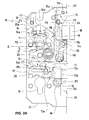
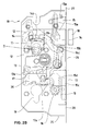
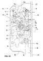
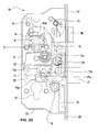
- FIG. 2A . 2 B . 2C . 2D . 2E and 2F each floor plans of a novel lock 10 are shown without lock cover.
- Fig. 2A . 2 B and 2C are shown successive states when extending the bolt 17, and in Fig. 2D . 2E and 2F consecutive states are shown when retracting the bolt 17 of the lock 10.
- Fig. 2A . 2 B . 2C . 2D . 2E and 2F essential elements contained in the lock case 25 of the lock 10 shown.
- a castle nut 11 (in Fig. 3A and 3B shown in more detail) is rotatably mounted in the lock case 25 about an axis of rotation perpendicular to the remote (not shown lock cover).
- the nut 11 has a front nut plate 11a and a rear nut plate 11b rigidly connected together by a square (not shown).
- a front cylindrical surface 11c on the front nut plate 11a and a rear cylindrical surface 11d on the rear Nut plate 11 b Via a front cylindrical surface 11c on the front nut plate 11a and a rear cylindrical surface 11d on the rear Nut plate 11 b, the nut 11 is rotatably mounted in complementary cylindrical recesses in the bottom or in the lid of the lock box 25.
- the axis of rotation of the lock nut 11 extends through the center of the square recess of the lock nut eleventh
- An intermediate member 12 (also in Fig. 3A and 3B shown in more detail) is slidably mounted in the lock case 25 along a vertical axis at three fixed pins F1, F2 and F3.
- the intermediate member 12 for this purpose three sliding slots 12e, 12f and 12g.
- the pin F1 projects through the sliding slot 12e
- the pin F2 protrudes through the sliding slot 12f
- the pin F3 protrudes through the sliding slot 12g.
- a lateral end face 12h of the intermediate member 12 is guided on the inside of the lock box wall 25a
- a lateral end face 12i of the intermediate member 12 is guided on another fixed pin F8.
- a arranged below the intermediate member 12 intermediate spring 21 abuts against a lower end face of the intermediate member 12 and pushes it up against the nut 11th
- a tumbler 13 (first tumbler, lever-operated tumbler) is rotatably mounted on a fixed pin F4.
- a tumbler spring 22 arranged above the tumbler 13 bears against an upper end face of the tumbler 13 and pushes it down against the latch 17.
- the tumbler 13 has the shape of a hook articulated on the pivot F4 and into a recess 17b, 17c or 17d of the bolt 17 can be pivoted into it.
- the lock nut 11, the intermediate member 12 and the tumbler 13 form a first drive train 11, 12, 13, with which by a (not shown) pusher, which is rotatably mounted on the nut 11, the latch 17 can be acted on the Block 17 to release or release.
- the lock nut 11 has four nut stops 11g, 11h, 11i and 11j in the form of laterally projecting protrusions.
- the stops 11 g and 11 h form a protruding leftward projection or one after right protruding projection on the front nut plate 11 a.
- the stops 11i (not visible in the figures) and 11j (only in Fig. 3A visible) form a protrusion projecting to the left or a protrusion protruding to the right on the rear nut plate 11b.
- the intermediate member 12 has four intermediate stops 12a, 12b, 12c and 12d in the form of pins projecting from the plate-like intermediate member 12 forward or rearward.
- the pins 12a and 12b form a left and a right stop, which protrudes from the intermediate member 12 to the front.
- the pins 12c (not visible in the figures) and 12d (only in FIG Fig. 3A visible) form a left and a right stop, which protrudes from the intermediate member 12 to the rear.
- the intermediate member 12 has another intermediate stop 12j at its lower end.
- the tumbler 13 has a tumbler 13a in the form of a shoulder (see Fig. 2A ).
- a driver arm 14 is rotatably mounted in the lock case 25 about the same axis of rotation as the lock nut 11 perpendicular to the remote (not shown lock cover).
- the MitOTHERarm 14 has a sliding slot 14a, through which the fixed pin F3 protrudes, and a sliding slot 14b through which a driving pin 11k (in Fig. 3A and 3B Not visible) of the nut 11 protrudes.
- the MitOTHERarm 14 is another plate-like element and can in a plane parallel to the remote (not shown lock cover) and parallel to the front and rear nut plate 11 a and 11 b (see Fig. 3A ) are pivoted.
- At its right end of the Mit psychologyarm 14 has a driving pin 14c.
- a sliding slot 15a and a sliding slot 15c are provided in the rack member 15.
- the pin F6 protrudes through the sliding slot 15a
- the pin F7 protrudes through the sliding slot 15c.
- the rack member has a further sliding slot 15b, through which the driving pin 14c of the driving arm 14 protrudes.
- a rack spring 23 abuts on a nose 15e of the rack member 15 and pushes it against its gravity upwards.
- the rack member 15 is coupled at its upper end to an upper drive rod 27 and coupled at its lower end to a lower drive rod 28.
- the rack spring 23 compensates the weight of the rack member 15 and the two drive rods 27,28.
- a gear 16 is rotatably mounted about a fixed axis of rotation.
- the gear 16 meshes with the rack portion 15d of the rack member 15 and with a rack portion 17a of the bolt 17th
- the lock nut 11, the driving arm 14, the rack member 15 and the gear 16 form a second drive train 11, 14, 15, 16 with the latch (not shown), which is mounted on the nut 11 in a rotationally fixed manner can be to extend the bolt 17 or retract.
- Another tumbler 20 (second tumbler, key-operated tumbler) is mounted on a fixed pin F5 displaceable and pivotable. It can be independent of the first tumbler 13 be operated by a lock cylinder 19 to block or release the latch 17 and to retract the latch 17 or extend.
- the dashed line D represents the orientation of a (not shown) pusher, the (not shown) square is clamped in the lock nut 11.
- the in Fig. 3C shown front nut plate recess with its front square surface 11 e and the rear nut plate recess with its rear square surface 11f each other slightly rotated and fixed to each other against rotation.
- the Miteckarm 14 is in its left end position, wherein it rests against the lock case wall 25a.
- the cam pin 11 k of the lock nut 11 projecting into the sliding slot 14 b is removed from the right end of the sliding slot 14 b. So there is a game between the associated attacks in the sliding slot 14b and the drive pin 11 k.
- the driving pin 14c of the driving arm 14 protrudes into the sliding slot 15b of the rack member 15 and is located in the immediate vicinity of the inclined lower inner surface of the sliding slot 15b or touches them.
- the meshing with the gear 16 through its rack portion 15d rack member 15 is in its upper end position, while the gear 16 is in its counterclockwise end position and the meshing via its rack portion 17a with the gear 16 latch 17, as I said, in its left end position ,
- the game consists solely or predominantly between the driving pin 11k of the lock nut 11 and the right end of the sliding slot 14b of the Mit Economicsarms 14th
- the intermediate member 12 engages and push the intermediate member 12 against the force of the intermediate member spring 21 down.
- the intermediate member 12 is from its upper End position moves against the force of the intermediate spring 21 over a portion of its stroke down, wherein the intermediate member stop 12j ( Fig. 3A . Fig. 3B )
- the tumbler stop 13a of the tumbler 13 touched and holds the tumbler 13 in a pivoted counterclockwise position.
- the handle-operated tumbler 13 is just enough swung out of the recess 17 b of the bolt 17 against the force of the tumbler spring 22 that the bolt 17 is free from horizontal movement.
- the Miteckarm 14 is still substantially in its left end position. He is only slightly pivoted clockwise.
- the cam pin 11k projecting into the slide slot 14b of the cam follower 11 is engaged with the right end of the slide slot 14b.
- the game between the associated attacks in the sliding slot 14 b and the driving pin 11 k no longer exists.
- the follower pin 14c of the follower arm 14 projects into the slide slot 15b of the rack member 15 and engages with the slanting lower inner surface of the slide slot 15b.
- the intermediate member 12 is moved from its upper end position against the force of the intermediate member spring 21 over its entire stroke down, wherein the intermediate member stop 12 j ( Fig. 3A . Fig. 3B ) at the lower end of the intermediate member 12 the tumbler stop 13a of the tumbler 13 still touched and holds the tumbler 13 in a pivoted counterclockwise end position.
- the handle-operated tumbler 13 is maximally swung out of the recess 17b of the bolt 17 against the force of the tumbler spring 22, and the latch 17 is, as already said, in its fully extended position.
- the Mit supportivearm 14 is in its right end position, ie the end position of its pivoting clockwise after he was taken from the drive pin 11 k of the lock nut 11 clockwise to the right.
- the projecting into the sliding slot 14 b driver pin 11 k of the lock nut 11 is still engaged with the right end of the sliding slot 14 b, ie no play between the associated stops in the sliding slot 14 b and the driving pin 11 k.
- the follower pin 14c of the follower arm 14 projects into the slide slot 15b of the rack member 15 and is still engaged with the slanting lower inner surface of the slide slot 15b.
- the handle-operated tumbler 13 is pivoted into the recess 17 c of the now extended latch 17, so that the latch 17 is blocked against a horizontal movement. This causes again on the one hand the force acting on the tumbler 13 gravity and on the other hand against the tumbler 13 downwardly pressing force of the tumbler spring 22.
- the intermediate member 12 is again in its upper end position in which the intermediate member stop 12j ( Fig. 3A . Fig. 3B ) is located at the lower end of the intermediate member 12 in the immediate vicinity of the tumbler stop 13a of the tumbler 13 or touches this stop 13a only, and in which the four intermediate member stops 12a, 12b, 12c, 12d ( Fig. 3A . Fig.
- the Mit psychologyarm 14 remains in its right end position.
- the cam pin 11 k of the lock nut 11 projecting into the sliding slot 14 b is removed from the left end of the sliding slot 14 b. So it is also in this direction a game before between the associated attacks in the sliding slot 14b and the driving pin 11 k. Therefore acts on the Mit psychologyarm 14 no counterclockwise him to the left rotating force.
- the driving pin 14c of the driving arm 14 protrudes into the sliding slot 15b of the rack member 15 and is located in the immediate vicinity of the inclined upper inner surface of the sliding slot 15b or touches them.
- the meshing with the gear 16 via its rack portion 15d rack member 15 remains in its lower end position, while the gear 16 remains in its counterclockwise end position and the rack via its portion 17a with the gear 16 meshing latch 17, as I said, in its right end position ,
- the Miteckarm 14 is still in its right end position.
- the cam pin 11k of the cam follower 11 projecting into the slide slot 14b is away from the left end of the slide slot 14b. There is still a game before between the associated attacks in the sliding slot 14b and the driving pin 11k.
- the driving pin 14c of the driving arm 14 protrudes into the sliding slot 15b of the rack member 15 and is located in the immediate vicinity of the inclined upper inner surface of the sliding slot 15b or touches them.
- the meshing with the gear 16 via its rack portion 15d rack member 15 is in its lower end position, while the gear 16 in its clockwise end position is and via its rack portion 17a with the gear 16 meshing latch 17, as I said, in its right end position.
- the game consists solely or predominantly between the driving pin 11 k of the lock nut 11 and the left end of the sliding slot 14 b of the Mit Economicsarms 14th
- the intermediate member 12 is moved from its upper end position against the force of the intermediate member spring 21 over a part of its stroke down, wherein the intermediate member stop 12j ( Fig. 3A . Fig. 3B ) At the lower end of the intermediate member 12 the tumbler stop 13a of the tumbler 13 touched and holds the tumbler 13 in a pivoted counterclockwise position.
- the handle-operated tumbler 13 is just enough swung out of the recess 17 d of the bolt 17 against the force of the tumbler spring 22 that the bolt 17 is free from horizontal movement.
- the Miteckarm 14 is still in its right end position.
- the driving pin 11k of the lock nut 11 projecting into the sliding slot 14b is now engaged with the left end of the sliding slot 14b.
- the game between the associated attacks in the sliding slot 14b and the driving pin 11k no longer exists.
- the follower pin 14c of the follower arm 14 projects into the slide slot 15b of the rack member 15 and engages with the inclined upper inner surface of the slide slot 15b.
- the meshing with the gear 16 via its rack portion 15d rack member 15 is still in its lower end position, while the gear 16 is still in its clockwise end position, and wherein over its rack portion 17a meshing with the gear 16 latch 17 still like said, in its right end position.
- the intermediate member 12 is moved from its upper end position against the force of the intermediate member spring 21 over its entire stroke down, wherein the intermediate member stop 12 j ( Fig. 3A . Fig. 3B ) at the lower end of the intermediate member 12 the tumbler stop 13a of the tumbler 13 still touched and holds the tumbler 13 in a pivoted counterclockwise end position.
- the lever-operated tumbler 13 is pivoted out of the recess 17 d of the bolt 17 against the force of the tumbler spring 22 maximum and is located now above the recess 17b of the bolt.
- the latch 17 is, as already said, in its fully retracted position.
- the Mit supportivearm 14 is in its left end position, i. the end position of its pivoting in the counterclockwise direction, after he was taken from the drive pin 11k of the lock nut 11 in the counterclockwise direction to the left.
- the cam pin 11k of the cam follower 11 projecting into the slide slot 14b is still engaged with the left end of the slide slot 14b, i. no play between the associated stops in the sliding slot 14b and the driving pin 11k.
- the follower pin 14c of the follower arm 14 projects into the slide slot 15b of the rack member 15 and is still engaged with the inclined upper inner surface of the slide slot 15b.
- the handle-operated tumbler 13 is pivoted back into the recess 17b of the now extended latch 17, so that the latch 17 is blocked relative to a horizontal movement. This causes again on the one hand the force acting on the tumbler 13 gravity and on the other hand against the tumbler 13 downwardly pressing force of the tumbler spring 22.
- the intermediate member 12 is again in its upper end position in which the intermediate member stop 12j ( Fig. 3A . Fig. 3B ) is located at the lower end of the intermediate member 12 in the immediate vicinity of the tumbler stop 13a of the tumbler 13 or touches this stop 13a only, and in which the four intermediate link stops 12a, 12b, 12c, 12d ( Fig. 3A . Fig.
- the Mit psychologyarm 14 remains in its left end position.
- the cam pin 11 k of the lock nut 11 projecting into the sliding slot 14 b is removed from the right end of the sliding slot 14 b.
- the driving pin 14c of the driving arm 14 protrudes into the sliding slot 15b of the rack member 15 and is located in the immediate vicinity of the inclined lower inner surface of the sliding slot 15b or touches them.
- the meshing with the gear 16 via its rack portion 15d rack member 15 is again in its lower end position, while the gear 16 remains in its clockwise end position and the toothed rod portion 17a with the gear 16 meshing latch 17, as I said, in its left end position is.
- the game consists solely or predominantly between the driving pin 11 k of the lock nut 11 and the right end of the sliding slot 14 b of the Mit Economicsarms 14th
- FIG. 3A is a perspective view of an assembly 11, 12 of the in Figs. 2A to 2F shown lock while Fig. 3B a the floor plan of Figs. 2A to 2F corresponding plan view of this assembly 11, 12 is.
- the assembly 11, 12 includes a lock nut 11 and an intermediate member 12.
- the lock nut 11 is in the lock case 25 (FIG. Fig. 2A to 2F ) rotatably mounted about an axis of rotation perpendicular to the remote (not shown lock cover).
- the lock nut 11 includes a front nut plate 11a and a rear nut plate 11b, which are rigidly connected to each other via a square (not shown).
- the nut 11 Via a front cylindrical surface 11c on the front nut plate 11a and a rear cylindrical surface 11d on the rear nut plate 11b, the nut 11 is rotatably supported in complementary cylindrical recesses (not shown) in the bottom or lid of the lock case 25.
- the axis of rotation of the lock nut 11 extends through the center of the square recess of the lock nut 11.
- the intermediate member 12 is in the lock case 25 (FIG. Figs. 2A to 2F ) slidably mounted along a vertical axis on three fixed pins F1, F2 and F3.
- the intermediate member 12 has for this purpose three sliding slots 12e, 12f and 12g.
- the pin F1 projects through the sliding slot 12e, the pin F2 protrudes through the sliding slot 12f, and the pin F3 protrudes through the sliding slot 12g.
- a lateral end face 12h of the intermediate member 12 is guided on the inside of the lock box wall 25a, and a lateral end face 12i of the intermediate member 12 is guided on another fixed pin F8.
- Fig. 3C are the square openings of the Fig. 3B shown enlarged.
- the square opening of the front nut plate 11a has a front square surface 11e.
- the square opening of the rear nut plate 11b has a rear square surface 11f.
- the two square openings are slightly rotated to each other, or the front square surface 11e and the rear square surface 11f are not quite parallel to each other. This is achieved by the two nut plates 11a and 11b pivoted against each other and then fixed in this mutually pivoted position.
- a plugged through the square opening of the lock nut 11 square can be permanently connected without play and rotation with the lock nut 11.
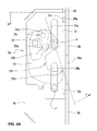
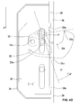
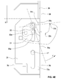
- FIG. 4A . 4B . 4C . 4D and 4E each floor plans of a pivot hook lock 30 according to the invention are shown, for example, one of the two lower pivot hook locks 30 in Fig. 1 can be. There are successive states when locking (extending the Swivel hook).
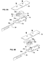
- Figs. 5A and 5B is an exploded view of the swing hook lock 30 of Fig. 4A to 4E shown in FIG Figs. 5A and 5B the pivoting hook is extended slightly or completely.
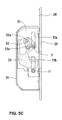
- FIG. 5C shows a section of the pivoting hook lock 30 along a plane in which the forces of the drive member 31, the first lever arm 32 and the second lever arm 33 act. The outlines of the arranged via the lever arms 32 and 33 drive member 31 are shown in phantom, while the sections are drawn by the two lever arms 32 and 33 hatched.
- the individual elements of the pivot hook lock 30 are housed in a lock case 34.
- the two essential elements of the pivoting hook lock 30 are a first lever arm 32 and a second lever arm 33, which together form a toggle lever arrangement 32, 33 whose second lever arm 33 is hook-shaped and forms the pivoting hook.
- the first lever arm 32 is articulated on a pin 33a of the second lever arm or pivot hook 33.
- the pivot hook 33 is articulated to a fixed pin F of the lock case bottom.
- a drive rod 28 (lower drive rod in Fig. 1 ) connected and guided on the faceplate 26 drive member 31, which has the shape of a drive plate, is used to drive the toggle lever assembly 32, 33 and is pivotally connected thereto for the first lever arm 32.
- the drive rod 28 is hooked via a hook 28a in a recess 31 d of the drive member 31.
- the drive member 31 has a first sliding slot 31 a, which can slide on a fixed pin F, and a second sliding slot 31 b, which can slide on another fixed pin F '.
- a further recess 31 e of the drive member 31 allows the attachment of a drive rod on the other side of the drive member 31st
- a pin 32 a of the first lever arm 32 protrudes into a pin 32 a complementary shaped pin hole 31 c of the drive member 31.
- the linear movement of the drive member 31 moves via this first pin / hole connection 32 a / 31 c, the first lever arm 32nd
- a pin 33a of the second lever arm 33 projects into a pin hole 32b of the first lever arm 32 complementarily shaped to this pin 33a.
- the movement of the first lever arm 32 moves the second lever arm 33, i.e., the second pin / hole connection 33a / 32b. the swing hook.
- the second lever arm 33 has a tip 33b. Between its center of rotation in the pin F and its tip 33b, the second lever arm 33 has a recess 33c.
- the second lever arm or pivoting hook 33 can be swung out of the lock case 34 through an opening 26a in the faceplate 26 in order to positively engage in a recess (not shown) in a window or door frame (not shown) that is complementary to the pivot hook 33.
- the pivot hook 33 can thus perform a rotational movement about the pin F in the direction of the angle ⁇ , wherein it exerts a torque M.
- the drive member 31 can thus perform a linear movement along the direction of the axis x, wherein it exerts a force K.
- Fig. 4A is the drive member 31 in an upper initial position along the direction x (displacement direction), and the pivot hook 33 is in a pivoted into the lock case 34 position along the angle ⁇ (Verschwenkungswinkel).
- Fig. 4B is the drive member 31 in a shifted from its upper initial position along the direction x down position, and the pivot hook 33 is in a pivoted along the angle ⁇ from the lock case 34 position.
- Fig. 4D is the drive member 31 in one of its upper initial position along the direction x further down shifted position, and the pivot hook 33 is in a along the angle ⁇ further out of the lock case 34 pivoted position.
- the toggle lever assembly 32/33 is in a kind of dead center.
- the line of action of the force K registered in the x-direction via the drive member 31 is orthogonal to the connecting line between the pin 32a of the first lever arm 32 and the pin 33a of the second lever arm or pivot hook 33.
- Fig. 4E is the drive member 31 in a shifted from its upper initial position along the direction x most downward position, and the pivot hook 33 is in a pivoted along the angle ⁇ farthest from the lock case 34 position beyond the in Fig. 4D shown dead center position of the toggle lever assembly 32/33.
- pivot hook 33 Only at the end of the pivoting (eg the pivoting between the state of Fig. 4C and the state of Fig. 4D as well as the pivoting between the state of Fig. 4D and the state of Fig. 4E ) must be overcome by the pivot hook 33 larger resistances.
- a Einrastschwelle be provided in the recess of the window or door frame, which must be overcome by the pivot hook 33 at the end of its pivoting stroke when extending.
- the pivot hook 33 at the end of the pivoting stroke of the pivoting hook 33 often much torque is required to bend warped window or door leaf in a flat shape.
Landscapes
- Engineering & Computer Science (AREA)
- Mechanical Engineering (AREA)
- Business, Economics & Management (AREA)
- Emergency Management (AREA)
- Structural Engineering (AREA)
- Lock And Its Accessories (AREA)
Priority Applications (1)
| Application Number | Priority Date | Filing Date | Title |
|---|---|---|---|
| EP09176211.2A EP2322744B1 (fr) | 2009-11-17 | 2009-11-17 | Serrure, serrure à crochet pivotant et système de verrouillage, notamment pour le verrouillage à plusieurs points d'une porte ou d'une fenêtre |
Applications Claiming Priority (1)
| Application Number | Priority Date | Filing Date | Title |
|---|---|---|---|
| EP09176211.2A EP2322744B1 (fr) | 2009-11-17 | 2009-11-17 | Serrure, serrure à crochet pivotant et système de verrouillage, notamment pour le verrouillage à plusieurs points d'une porte ou d'une fenêtre |
Publications (2)
| Publication Number | Publication Date |
|---|---|
| EP2322744A1 true EP2322744A1 (fr) | 2011-05-18 |
| EP2322744B1 EP2322744B1 (fr) | 2018-10-31 |
Family
ID=41800629
Family Applications (1)
| Application Number | Title | Priority Date | Filing Date |
|---|---|---|---|
| EP09176211.2A Active EP2322744B1 (fr) | 2009-11-17 | 2009-11-17 | Serrure, serrure à crochet pivotant et système de verrouillage, notamment pour le verrouillage à plusieurs points d'une porte ou d'une fenêtre |
Country Status (1)
| Country | Link |
|---|---|
| EP (1) | EP2322744B1 (fr) |
Cited By (2)
| Publication number | Priority date | Publication date | Assignee | Title |
|---|---|---|---|---|
| WO2019155499A1 (fr) * | 2018-02-07 | 2019-08-15 | Cisa S.P.A. | Ensemble périphérique pour serrures multipoints |
| EP4116529A1 (fr) | 2021-07-07 | 2023-01-11 | Carl Fuhr GmbH & Co. KG | Unité de verrouillage |
Citations (6)
| Publication number | Priority date | Publication date | Assignee | Title |
|---|---|---|---|---|
| EP0619409A1 (fr) * | 1993-03-26 | 1994-10-12 | Roto Frank Eisenwarenfabrik Aktiengesellschaft | Serrure à plusieurs pênes |
| EP0848124A2 (fr) * | 1996-12-12 | 1998-06-17 | KARL FLIETHER GmbH & Co. | Serrure avec pêne demi-tour et pêne dormant |
| DE10202088A1 (de) * | 2001-01-19 | 2002-07-25 | Msl Schloss Und Beschlaegefabr | Schloss |
| EP1260660A2 (fr) * | 2001-05-23 | 2002-11-27 | Talleres De Escoriaza, S.A. | Dispositif d'actionnement d'un pêne d'une serrure |
| EP1574644A2 (fr) * | 2004-03-12 | 2005-09-14 | Carl Fuhr GmbH & Co. KG | Système de verrouillage pour portes, fenêtres ou similaires, notamment crémone-serrure avec fonction anti-panique et avec plusieurs points de condamnation |
| CH694970A5 (de) | 2000-04-19 | 2005-10-14 | Glutz Ag | Wahlweise bedienbares Türschloss. |
-
2009
- 2009-11-17 EP EP09176211.2A patent/EP2322744B1/fr active Active
Patent Citations (6)
| Publication number | Priority date | Publication date | Assignee | Title |
|---|---|---|---|---|
| EP0619409A1 (fr) * | 1993-03-26 | 1994-10-12 | Roto Frank Eisenwarenfabrik Aktiengesellschaft | Serrure à plusieurs pênes |
| EP0848124A2 (fr) * | 1996-12-12 | 1998-06-17 | KARL FLIETHER GmbH & Co. | Serrure avec pêne demi-tour et pêne dormant |
| CH694970A5 (de) | 2000-04-19 | 2005-10-14 | Glutz Ag | Wahlweise bedienbares Türschloss. |
| DE10202088A1 (de) * | 2001-01-19 | 2002-07-25 | Msl Schloss Und Beschlaegefabr | Schloss |
| EP1260660A2 (fr) * | 2001-05-23 | 2002-11-27 | Talleres De Escoriaza, S.A. | Dispositif d'actionnement d'un pêne d'une serrure |
| EP1574644A2 (fr) * | 2004-03-12 | 2005-09-14 | Carl Fuhr GmbH & Co. KG | Système de verrouillage pour portes, fenêtres ou similaires, notamment crémone-serrure avec fonction anti-panique et avec plusieurs points de condamnation |
Cited By (3)
| Publication number | Priority date | Publication date | Assignee | Title |
|---|---|---|---|---|
| WO2019155499A1 (fr) * | 2018-02-07 | 2019-08-15 | Cisa S.P.A. | Ensemble périphérique pour serrures multipoints |
| EP4116529A1 (fr) | 2021-07-07 | 2023-01-11 | Carl Fuhr GmbH & Co. KG | Unité de verrouillage |
| DE102021117521A1 (de) | 2021-07-07 | 2023-01-12 | Carl Fuhr GmbH & Co. KG. | Verriegelungseinheit |
Also Published As
| Publication number | Publication date |
|---|---|
| EP2322744B1 (fr) | 2018-10-31 |
Similar Documents
| Publication | Publication Date | Title |
|---|---|---|
| EP1932989B1 (fr) | Système de fermeture pour portes, fenêtres ou analogues, en particulier crémone-serrure à fonction d'urgence et de verrouillage à plusieurs points | |
| DE3447748C2 (fr) | ||
| EP2264268B2 (fr) | Crémone serrure | |
| EP1574644A2 (fr) | Système de verrouillage pour portes, fenêtres ou similaires, notamment crémone-serrure avec fonction anti-panique et avec plusieurs points de condamnation | |
| DE19813166A1 (de) | Türschloßanordnung, vorzugsweise Treibstangenschloßanordnung | |
| EP0954667B1 (fr) | Serrure a pene demi-tour pour porte ou fenetre | |
| EP0833997B1 (fr) | Dispositif de fermeture a organe d'arret du battant d'une porte | |
| EP3070238B1 (fr) | Dispositif de verrouillage pour une porte ou une fenêtre | |
| EP3426867B1 (fr) | Serrure | |
| DE4114007C2 (de) | Treibstangenverschluß | |
| DE102004013646A1 (de) | Panikschloss | |
| EP2322744B1 (fr) | Serrure, serrure à crochet pivotant et système de verrouillage, notamment pour le verrouillage à plusieurs points d'une porte ou d'une fenêtre | |
| DE102015000606A1 (de) | Verriegelungsvorrichtung für einen schwenkbar gelagerten Flügel | |
| DE202009016137U1 (de) | Treibstangenschloss mit Panikfunktion und Mehrfachverriegelung | |
| AT392819B (de) | Schloss, insbesondere panikschloss | |
| AT519509A2 (de) | Türschloss | |
| EP1672153B1 (fr) | Serrure avec pêne dormant et dispositif de commande du pêne dormant | |
| DE102013013547B4 (de) | Schloss mit Riegel mit Entriegelungspin | |
| EP3628801B1 (fr) | Dispositif de fermeture pour une porte et procédé pour ouvrir une porte | |
| DE3831529A1 (de) | Treibstangenverschluss | |
| EP3216952B1 (fr) | Dispositif de verrouillage | |
| DE2518318A1 (de) | Verriegelungsvorrichtung | |
| EP3215696B1 (fr) | Serrure | |
| EP0439478B1 (fr) | Serrure a verrouillage automatique | |
| EP4116529B1 (fr) | Unité de verrouillage |
Legal Events
| Date | Code | Title | Description |
|---|---|---|---|
| PUAI | Public reference made under article 153(3) epc to a published international application that has entered the european phase |
Free format text: ORIGINAL CODE: 0009012 |
|
| AK | Designated contracting states |
Kind code of ref document: A1 Designated state(s): AT BE BG CH CY CZ DE DK EE ES FI FR GB GR HR HU IE IS IT LI LT LU LV MC MK MT NL NO PL PT RO SE SI SK SM TR |
|
| AX | Request for extension of the european patent |
Extension state: AL BA RS |
|
| 17P | Request for examination filed |
Effective date: 20111108 |
|
| GRAP | Despatch of communication of intention to grant a patent |
Free format text: ORIGINAL CODE: EPIDOSNIGR1 |
|
| INTG | Intention to grant announced |
Effective date: 20180618 |
|
| GRAS | Grant fee paid |
Free format text: ORIGINAL CODE: EPIDOSNIGR3 |
|
| GRAA | (expected) grant |
Free format text: ORIGINAL CODE: 0009210 |
|
| AK | Designated contracting states |
Kind code of ref document: B1 Designated state(s): AT BE BG CH CY CZ DE DK EE ES FI FR GB GR HR HU IE IS IT LI LT LU LV MC MK MT NL NO PL PT RO SE SI SK SM TR |
|
| REG | Reference to a national code |
Ref country code: CH Ref legal event code: EP Ref country code: GB Ref legal event code: FG4D Free format text: NOT ENGLISH |
|
| REG | Reference to a national code |
Ref country code: AT Ref legal event code: REF Ref document number: 1059587 Country of ref document: AT Kind code of ref document: T Effective date: 20181115 |
|
| REG | Reference to a national code |
Ref country code: DE Ref legal event code: R096 Ref document number: 502009015406 Country of ref document: DE |
|
| REG | Reference to a national code |
Ref country code: IE Ref legal event code: FG4D Free format text: LANGUAGE OF EP DOCUMENT: GERMAN |
|
| REG | Reference to a national code |
Ref country code: NL Ref legal event code: FP |
|
| REG | Reference to a national code |
Ref country code: LT Ref legal event code: MG4D |
|
| PG25 | Lapsed in a contracting state [announced via postgrant information from national office to epo] |
Ref country code: FI Free format text: LAPSE BECAUSE OF FAILURE TO SUBMIT A TRANSLATION OF THE DESCRIPTION OR TO PAY THE FEE WITHIN THE PRESCRIBED TIME-LIMIT Effective date: 20181031 Ref country code: NO Free format text: LAPSE BECAUSE OF FAILURE TO SUBMIT A TRANSLATION OF THE DESCRIPTION OR TO PAY THE FEE WITHIN THE PRESCRIBED TIME-LIMIT Effective date: 20190131 Ref country code: IS Free format text: LAPSE BECAUSE OF FAILURE TO SUBMIT A TRANSLATION OF THE DESCRIPTION OR TO PAY THE FEE WITHIN THE PRESCRIBED TIME-LIMIT Effective date: 20190228 Ref country code: ES Free format text: LAPSE BECAUSE OF FAILURE TO SUBMIT A TRANSLATION OF THE DESCRIPTION OR TO PAY THE FEE WITHIN THE PRESCRIBED TIME-LIMIT Effective date: 20181031 Ref country code: LV Free format text: LAPSE BECAUSE OF FAILURE TO SUBMIT A TRANSLATION OF THE DESCRIPTION OR TO PAY THE FEE WITHIN THE PRESCRIBED TIME-LIMIT Effective date: 20181031 Ref country code: HR Free format text: LAPSE BECAUSE OF FAILURE TO SUBMIT A TRANSLATION OF THE DESCRIPTION OR TO PAY THE FEE WITHIN THE PRESCRIBED TIME-LIMIT Effective date: 20181031 Ref country code: PL Free format text: LAPSE BECAUSE OF FAILURE TO SUBMIT A TRANSLATION OF THE DESCRIPTION OR TO PAY THE FEE WITHIN THE PRESCRIBED TIME-LIMIT Effective date: 20181031 Ref country code: LT Free format text: LAPSE BECAUSE OF FAILURE TO SUBMIT A TRANSLATION OF THE DESCRIPTION OR TO PAY THE FEE WITHIN THE PRESCRIBED TIME-LIMIT Effective date: 20181031 Ref country code: BG Free format text: LAPSE BECAUSE OF FAILURE TO SUBMIT A TRANSLATION OF THE DESCRIPTION OR TO PAY THE FEE WITHIN THE PRESCRIBED TIME-LIMIT Effective date: 20190131 |
|
| PG25 | Lapsed in a contracting state [announced via postgrant information from national office to epo] |
Ref country code: GR Free format text: LAPSE BECAUSE OF FAILURE TO SUBMIT A TRANSLATION OF THE DESCRIPTION OR TO PAY THE FEE WITHIN THE PRESCRIBED TIME-LIMIT Effective date: 20190201 Ref country code: SE Free format text: LAPSE BECAUSE OF FAILURE TO SUBMIT A TRANSLATION OF THE DESCRIPTION OR TO PAY THE FEE WITHIN THE PRESCRIBED TIME-LIMIT Effective date: 20181031 Ref country code: PT Free format text: LAPSE BECAUSE OF FAILURE TO SUBMIT A TRANSLATION OF THE DESCRIPTION OR TO PAY THE FEE WITHIN THE PRESCRIBED TIME-LIMIT Effective date: 20190301 |
|
| PG25 | Lapsed in a contracting state [announced via postgrant information from national office to epo] |
Ref country code: CZ Free format text: LAPSE BECAUSE OF FAILURE TO SUBMIT A TRANSLATION OF THE DESCRIPTION OR TO PAY THE FEE WITHIN THE PRESCRIBED TIME-LIMIT Effective date: 20181031 Ref country code: LU Free format text: LAPSE BECAUSE OF NON-PAYMENT OF DUE FEES Effective date: 20181117 Ref country code: IT Free format text: LAPSE BECAUSE OF FAILURE TO SUBMIT A TRANSLATION OF THE DESCRIPTION OR TO PAY THE FEE WITHIN THE PRESCRIBED TIME-LIMIT Effective date: 20181031 Ref country code: DK Free format text: LAPSE BECAUSE OF FAILURE TO SUBMIT A TRANSLATION OF THE DESCRIPTION OR TO PAY THE FEE WITHIN THE PRESCRIBED TIME-LIMIT Effective date: 20181031 |
|
| REG | Reference to a national code |
Ref country code: DE Ref legal event code: R097 Ref document number: 502009015406 Country of ref document: DE |
|
| REG | Reference to a national code |
Ref country code: BE Ref legal event code: MM Effective date: 20181130 |
|
| REG | Reference to a national code |
Ref country code: IE Ref legal event code: MM4A |
|
| PG25 | Lapsed in a contracting state [announced via postgrant information from national office to epo] |
Ref country code: MC Free format text: LAPSE BECAUSE OF FAILURE TO SUBMIT A TRANSLATION OF THE DESCRIPTION OR TO PAY THE FEE WITHIN THE PRESCRIBED TIME-LIMIT Effective date: 20181031 Ref country code: EE Free format text: LAPSE BECAUSE OF FAILURE TO SUBMIT A TRANSLATION OF THE DESCRIPTION OR TO PAY THE FEE WITHIN THE PRESCRIBED TIME-LIMIT Effective date: 20181031 Ref country code: SM Free format text: LAPSE BECAUSE OF FAILURE TO SUBMIT A TRANSLATION OF THE DESCRIPTION OR TO PAY THE FEE WITHIN THE PRESCRIBED TIME-LIMIT Effective date: 20181031 Ref country code: SK Free format text: LAPSE BECAUSE OF FAILURE TO SUBMIT A TRANSLATION OF THE DESCRIPTION OR TO PAY THE FEE WITHIN THE PRESCRIBED TIME-LIMIT Effective date: 20181031 Ref country code: RO Free format text: LAPSE BECAUSE OF FAILURE TO SUBMIT A TRANSLATION OF THE DESCRIPTION OR TO PAY THE FEE WITHIN THE PRESCRIBED TIME-LIMIT Effective date: 20181031 |
|
| PLBE | No opposition filed within time limit |
Free format text: ORIGINAL CODE: 0009261 |
|
| STAA | Information on the status of an ep patent application or granted ep patent |
Free format text: STATUS: NO OPPOSITION FILED WITHIN TIME LIMIT |
|
| 26N | No opposition filed |
Effective date: 20190801 |
|
| PG25 | Lapsed in a contracting state [announced via postgrant information from national office to epo] |
Ref country code: IE Free format text: LAPSE BECAUSE OF NON-PAYMENT OF DUE FEES Effective date: 20181117 Ref country code: SI Free format text: LAPSE BECAUSE OF FAILURE TO SUBMIT A TRANSLATION OF THE DESCRIPTION OR TO PAY THE FEE WITHIN THE PRESCRIBED TIME-LIMIT Effective date: 20181031 Ref country code: FR Free format text: LAPSE BECAUSE OF NON-PAYMENT OF DUE FEES Effective date: 20181231 |
|
| PG25 | Lapsed in a contracting state [announced via postgrant information from national office to epo] |
Ref country code: BE Free format text: LAPSE BECAUSE OF NON-PAYMENT OF DUE FEES Effective date: 20181130 |
|
| PG25 | Lapsed in a contracting state [announced via postgrant information from national office to epo] |
Ref country code: MT Free format text: LAPSE BECAUSE OF FAILURE TO SUBMIT A TRANSLATION OF THE DESCRIPTION OR TO PAY THE FEE WITHIN THE PRESCRIBED TIME-LIMIT Effective date: 20181031 |
|
| PG25 | Lapsed in a contracting state [announced via postgrant information from national office to epo] |
Ref country code: TR Free format text: LAPSE BECAUSE OF FAILURE TO SUBMIT A TRANSLATION OF THE DESCRIPTION OR TO PAY THE FEE WITHIN THE PRESCRIBED TIME-LIMIT Effective date: 20181031 |
|
| PG25 | Lapsed in a contracting state [announced via postgrant information from national office to epo] |
Ref country code: CY Free format text: LAPSE BECAUSE OF FAILURE TO SUBMIT A TRANSLATION OF THE DESCRIPTION OR TO PAY THE FEE WITHIN THE PRESCRIBED TIME-LIMIT Effective date: 20181031 Ref country code: HU Free format text: LAPSE BECAUSE OF FAILURE TO SUBMIT A TRANSLATION OF THE DESCRIPTION OR TO PAY THE FEE WITHIN THE PRESCRIBED TIME-LIMIT; INVALID AB INITIO Effective date: 20091117 Ref country code: MK Free format text: LAPSE BECAUSE OF NON-PAYMENT OF DUE FEES Effective date: 20181031 |
|
| P01 | Opt-out of the competence of the unified patent court (upc) registered |
Effective date: 20230630 |
|
| PGFP | Annual fee paid to national office [announced via postgrant information from national office to epo] |
Ref country code: NL Payment date: 20231120 Year of fee payment: 15 |
|
| PGFP | Annual fee paid to national office [announced via postgrant information from national office to epo] |
Ref country code: GB Payment date: 20231123 Year of fee payment: 15 |
|
| PGFP | Annual fee paid to national office [announced via postgrant information from national office to epo] |
Ref country code: DE Payment date: 20231121 Year of fee payment: 15 Ref country code: CH Payment date: 20231201 Year of fee payment: 15 Ref country code: AT Payment date: 20231121 Year of fee payment: 15 |