EP2322695A1 - Verfahren zur Herstellung eines Einkristalls aus Silizium durch Umschmelzen von Granulat - Google Patents
Verfahren zur Herstellung eines Einkristalls aus Silizium durch Umschmelzen von Granulat Download PDFInfo
- Publication number
- EP2322695A1 EP2322695A1 EP10188864A EP10188864A EP2322695A1 EP 2322695 A1 EP2322695 A1 EP 2322695A1 EP 10188864 A EP10188864 A EP 10188864A EP 10188864 A EP10188864 A EP 10188864A EP 2322695 A1 EP2322695 A1 EP 2322695A1
- Authority
- EP
- European Patent Office
- Prior art keywords
- plate
- single crystal
- silicon
- induction heating
- heating coil
- Prior art date
- Legal status (The legal status is an assumption and is not a legal conclusion. Google has not performed a legal analysis and makes no representation as to the accuracy of the status listed.)
- Granted
Links
- 229910052710 silicon Inorganic materials 0.000 title claims abstract description 44
- 239000010703 silicon Substances 0.000 title claims abstract description 44
- 239000013078 crystal Substances 0.000 title claims abstract description 33
- 239000008187 granular material Substances 0.000 title claims abstract description 16
- 238000010438 heat treatment Methods 0.000 claims abstract description 34
- 230000006698 induction Effects 0.000 claims abstract description 33
- 239000000155 melt Substances 0.000 claims abstract description 19
- 238000004519 manufacturing process Methods 0.000 claims abstract description 5
- 238000000034 method Methods 0.000 claims description 8
- XUIMIQQOPSSXEZ-UHFFFAOYSA-N Silicon Chemical compound [Si] XUIMIQQOPSSXEZ-UHFFFAOYSA-N 0.000 description 34
- 239000012071 phase Substances 0.000 description 7
- 230000008018 melting Effects 0.000 description 6
- 238000002844 melting Methods 0.000 description 6
- 230000008014 freezing Effects 0.000 description 5
- 238000007710 freezing Methods 0.000 description 5
- 239000007788 liquid Substances 0.000 description 5
- 239000007791 liquid phase Substances 0.000 description 5
- 239000007790 solid phase Substances 0.000 description 4
- 239000007787 solid Substances 0.000 description 2
- 238000001816 cooling Methods 0.000 description 1
- 230000008021 deposition Effects 0.000 description 1
- 238000000605 extraction Methods 0.000 description 1
- 239000000463 material Substances 0.000 description 1
- SBEQWOXEGHQIMW-UHFFFAOYSA-N silicon Chemical compound [Si].[Si] SBEQWOXEGHQIMW-UHFFFAOYSA-N 0.000 description 1
Images

Classifications
-
- C—CHEMISTRY; METALLURGY
- C30—CRYSTAL GROWTH
- C30B—SINGLE-CRYSTAL GROWTH; UNIDIRECTIONAL SOLIDIFICATION OF EUTECTIC MATERIAL OR UNIDIRECTIONAL DEMIXING OF EUTECTOID MATERIAL; REFINING BY ZONE-MELTING OF MATERIAL; PRODUCTION OF A HOMOGENEOUS POLYCRYSTALLINE MATERIAL WITH DEFINED STRUCTURE; SINGLE CRYSTALS OR HOMOGENEOUS POLYCRYSTALLINE MATERIAL WITH DEFINED STRUCTURE; AFTER-TREATMENT OF SINGLE CRYSTALS OR A HOMOGENEOUS POLYCRYSTALLINE MATERIAL WITH DEFINED STRUCTURE; APPARATUS THEREFOR
- C30B13/00—Single-crystal growth by zone-melting; Refining by zone-melting
- C30B13/16—Heating of the molten zone
- C30B13/20—Heating of the molten zone by induction, e.g. hot wire technique
-
- C—CHEMISTRY; METALLURGY
- C30—CRYSTAL GROWTH
- C30B—SINGLE-CRYSTAL GROWTH; UNIDIRECTIONAL SOLIDIFICATION OF EUTECTIC MATERIAL OR UNIDIRECTIONAL DEMIXING OF EUTECTOID MATERIAL; REFINING BY ZONE-MELTING OF MATERIAL; PRODUCTION OF A HOMOGENEOUS POLYCRYSTALLINE MATERIAL WITH DEFINED STRUCTURE; SINGLE CRYSTALS OR HOMOGENEOUS POLYCRYSTALLINE MATERIAL WITH DEFINED STRUCTURE; AFTER-TREATMENT OF SINGLE CRYSTALS OR A HOMOGENEOUS POLYCRYSTALLINE MATERIAL WITH DEFINED STRUCTURE; APPARATUS THEREFOR
- C30B29/00—Single crystals or homogeneous polycrystalline material with defined structure characterised by the material or by their shape
- C30B29/02—Elements
- C30B29/06—Silicon
Definitions
- the invention relates to a method for producing a single crystal of silicon by remelting granules by means of a device comprising a rotating plate of silicon with a central opening and a conical tube surrounding the opening and extending below the plate of silicon silicon, further comprising a first induction heating coil disposed over the silicon plate for melting silicon, and finally a second induction heating coil disposed below the silicon plate for crystallizing molten silicon.
- zone extraction which is also called FZ (floating zone method).
- FZ floating zone method
- the particular difference is that, instead of a polycrystalline feed rod made of silicon, polycrystalline granules of silicon are remelted.
- the granules can be obtained by deposition in the fluidized bed.
- induction heating coils in order to melt the granules and to crystallize the molten granules, separate induction heating coils (“inductor coils”) are used which are located above or below a rotating silicon plate.
- the granules of silicon are melted by means of the first induction heating coil and flow as a film of liquid silicon through the central opening and the conical tube of the plate and form a melt, which, controlled by the second induction heating coil, is crystallized into a growing single crystal of silicon.
- the DE 10 2008 013 326 A1 comprises the description of an induction heating coil for melting granules having segments projecting in the center of the lower side, by means of which the film of liquid silicon flowing from the plate and through the conical tube to the melt can be heated and kept liquid.
- the object of the present invention is to take measures to reliably prevent such a freezing of the pipe end of the conical tube.
- the object is achieved by a method for producing a single crystal of silicon by remelting of granules, comprising crystallizing a cone-shaped widened portion of the single crystal by means of an induction heating coil disposed below a rotating plate of silicon; and supplying inductively molten silicon through a conical tube of the plate enclosing a central opening of the plate and extending below the plate to a melt located on the conically expanded portion of the single crystal and contacting a tube end of the conical Pipe has, with the help of the arranged below the plate induction heating coil sufficient energy is provided so that the outer diameter of the pipe end is not smaller is 15 mm as long as the conical-extended portion of the single crystal has a diameter of 15 to 30 mm and is crystallized.
- the conical tube which is still closed at this time by a layer of solid silicon at the end of the tube, is melted by means of the induction heating coil located under the plate at the tube end, forming a small volume of liquid silicon.
- the tube end of the conical tube is brought as short as possible to the inner hole of the induction heating coil, so that a high energy density can be inductively transmitted to the tube end and the forming volume of molten silicon.
- a single crystal seed crystal is attached to the volume of molten silicon and, according to the FZ method, first a neck, then a conical up to a final diameter expanded portion of the single crystal and finally a section of constant nominal diameter crystallized.
- the necessary material of molten silicon is provided by melting the layer closing the tube end, by partially melting the conical tube from the tube end, by partially melting the plate from above, and later by melting granules of silicon.
- a melt forms on the conically-expanded portion extending through the inner hole of the induction heating coil disposed below the plate and having contact with the tube end of the conical tube via a solid-liquid phase boundary.
- the reason for this is considered by the inventors to be that the outer diameter of the pipe end of the conical pipe is not sufficiently large to be large enough during a critical phase in which the conical expanded portion of the single crystal has a diameter of 15 to 30 mm and is crystallized to allow the freezing avoiding course of the solid / liquid phase boundary between the pipe end and the melt.
- such a course of the phase boundary is ensured by using the arranged below the plate induction heating coil, the tube is melted from the pipe end to the extent that the outer diameter of the pipe end during the critical phase is not less than 15 mm.
- Fig. 1 shows the crystallizing, conically expanded section 1 of the single crystal and a part of the previously crystallized thin neck 2.
- the further crystal growth is nourished by the, lying on the conically widened section melt 3 of silicon and through the film 4 of molten Silicon flowing on the inner wall of the conical tube 6 of the plate 5 made of silicon to the melt 3.
- the film is formed from the first induction heating coil 7 disposed above the plate by fusing the plate surface and kept liquid. At a later time, this induction heating coil 7 is also used to inductively melt granules 13 of silicon, which is conveyed through a funnel 12 to the plate 5, melt.
- the film 4 is then mainly formed by molten granules.
- the induction heating coil 7 preferably has the features of in the DE 10 2008 013 326 A1 described induction heating coil.
- the lower side of the plate 5 is cooled by, for example, a cooling device 10.
- the second induction heating coil 8 disposed under the silicon plate 5 is operated mainly in the same manner as in the FZ method, first by the section which is conically enlarged to a final diameter 1 and then crystallized to control the section of the single crystal with the same nominal diameter.
- the critical phase when the diameter of the cone-shaped expanded portion 1 of the single crystal has grown to 15 to 30 mm and the outer diameter D of the pipe end of the cone-shaped pipe 6 is smaller than 15 mm, there is a high possibility that the cone-shaped pipe 6 at the tube end freezes.
- the smaller the outer diameter D the steeper the solid / liquid phase boundary 9 falls from the triple point T at the outer edge of the tube end of the conical tube 6 inwards. Because of the slope, the triple point T tends to shift inwardly along the phase boundary 9. As a result, the distance between the melt 3 and the second induction heating coil 8 becomes larger, whereby less energy is transferred to the melt 3 and the melt 3 threatens to freeze at the tube end of the conical tube 6.
- the cone-shaped tube 6 is melted from the tube end to the extent that the outer diameter D of the tube end during the critical phase is not less than 15 mm.
- the solid / liquid phase boundary rises from the triple point T at the outer edge of the pipe end of the cone-shaped tube 6 inwards. The slope is sufficient that the triple point T remains stable at the outer edge of the pipe end of the conical tube 6, and the distance between the second induction heating coil 8 and the melt 3 is not greater.
- the diameter of the inner hole 11 of the second induction heating coil 8 is larger than the diameter of the melt 3, and is preferably more than 30 mm and not more than 40 mm.
- the ratio of the outer diameter of the pipe end of the cone-shaped pipe 6 and the diameter of the inner hole 11 during the critical phase is preferably 1: 3 or greater, more preferably 1: 3 to 4: 5.
- the conically expanded portion 1 has already grown to a diameter of more than 30 mm, the amount of molten silicon subsequent to the melt usually suffices to prevent the tube end of the conical tube 6 from freezing, even if the outside diameter D of the pipe end of the conical tube falls below 15 mm.
Landscapes
- Chemical & Material Sciences (AREA)
- Engineering & Computer Science (AREA)
- Crystallography & Structural Chemistry (AREA)
- Materials Engineering (AREA)
- Metallurgy (AREA)
- Organic Chemistry (AREA)
- Crystals, And After-Treatments Of Crystals (AREA)
- Liquid Deposition Of Substances Of Which Semiconductor Devices Are Composed (AREA)
- Silicon Compounds (AREA)
Abstract
Description
- Gegenstand der Erfindung ist ein Verfahren zur Herstellung eines Einkristalls aus Silizium durch Umschmelzen von Granulat mit Hilfe einer Vorrichtung, die eine sich drehende Platte aus Silizium mit einer zentralen Öffnung umfasst und ein, die Öffnung umschließendes und sich unter die Platte aus Silizium erstreckendes, konisches Rohr aus Silizium, des Weiteren eine erste, über der Platte aus Silizium angeordnete Induktionsheizspule zum Schmelzen von Silizium und schließlich eine zweite, unter der Platte aus Silizium angeordnete Induktionsheizspule zum Kristallisieren von geschmolzenem Silizium.
- Das Verfahren ähnelt dem Zonenziehen, das auch FZ-Verfahren ("floating zone method") genannt wird. Der besondere Unterschied besteht darin, dass an Stelle eines polykristallinen Vorratsstabes ("feed rod") aus Silizium polykristallines Granulat aus Silizium umgeschmolzen wird. Das Granulat kann durch Abscheiden in der Wirbelschicht erhalten werden. Zum Schmelzen des Granulats und zum Kristallisieren des geschmolzenen Granulats werden jeweils eigene Induktionsheizspulen ("inductor coils") eingesetzt, die sich über, beziehungsweise unter einer sich drehenden Platte aus Silizium befinden. Das Granulat aus Silizium wird mit Hilfe der ersten Induktionsheizspule geschmolzen und fließt als Film aus flüssigem Silizium durch die zentrale Öffnung und das konische Rohr der Platte und bildet eine Schmelze, die, von der zweiten Induktionsheizspule gesteuert, zu einem wachsenden Einkristall aus Silizium kristallisiert wird.
- In der
DE 102 04 178 A1 sind das Verfahren und Vorrichtungen näher beschrieben, die zur Durchführung des Verfahrens geeignet sind. - Die
DE 10 2008 013 326 A1 umfasst die Beschreibung einer Induktionsheizspule zum Schmelzen von Granulat, die im Zentrum der unteren Seite hervorstehende Segmente aufweist, mit deren Hilfe der, von der Platte und durch das konische Rohr zur Schmelze fließende Film aus flüssigem Silizium erhitzt und flüssig gehalten werden kann. - Es hat sich jedoch gezeigt, dass auch bei Verwendung einer derartigen Spule nicht zuverlässig verhindert werden kann, dass das Rohrende des konischen Rohrs im Verlauf des Wachstums eines konusförmig erweiterten Abschnitts des Einkristalls immer enger wird und schließlich durch, in festen Zustand übergehendes Silizium zufriert.
- Aufgabe der vorliegenden Erfindung ist es, Maßnahmen zu ergreifen, die ein derartiges Zufrieren des Rohrendes des konischen Rohrs zuverlässig verhindern.
- Gelöst wird die Aufgabe durch ein Verfahren zur Herstellung eines Einkristalls aus Silizium durch Umschmelzen von Granulat, umfassend
das Kristallisieren eines konusförmig erweiterten Abschnitts des Einkristalls mit Hilfe einer Induktionsheizspule, die unter einer sich drehenden Platte aus Silizium angeordnet ist; und das Zuführen von induktiv geschmolzenem Silizium durch ein konisches Rohr der Platte, das eine zentrale Öffnung der Platte umschließt und sich unter die Platte erstreckt, zu einer Schmelze, die sich auf dem konusförmig erweiterten Abschnitt des Einkristalls befindet und die Kontakt zu einem Rohrende des konischen Rohrs hat, wobei mit Hilfe der unter der Platte angeordneten Induktionsheizspule ausreichend Energie bereitgestellt wird, damit der Außendurchmesser des Rohrendes nicht kleiner
als 15 mm ist, solange der konusförmig erweiterte Abschnitt des Einkristalls einen Durchmesser von 15 bis 30 mm aufweist und kristallisiert wird. - Am Anfang des Verfahrens wird das konische Rohr, das zu diesem Zeitpunkt am Rohrende noch durch eine Schicht aus festem Silizium verschlossen ist, mit Hilfe der, unter der Platte angeordneten Induktionsheizspule am Rohrende angeschmolzen, wobei ein kleines Volumen an flüssigem Silizium entsteht. Das Rohrende des konischen Rohrs wird auf einen möglichst kurzen Abstand zum Innenloch der Induktionsheizspule gebracht, damit eine hohe Energiedichte auf das Rohrende und das sich bildende Volumen von geschmolzenem Silizium induktiv übertragen werden kann. Anschließend wird ein einkristalliner Impfkristall an das Volumen von geschmolzenem Silizium angesetzt und, entsprechend der FZ-Methode, zunächst ein Dünnhals ("neck"), dann ein, bis zu einem Enddurchmesser konusförmig erweiterter Abschnitt des Einkristalls und schließlich ein Abschnitt mit konstantem Soll-Durchmesser kristallisiert. Das dafür notwendige Material an geschmolzenem Silizium wird durch Schmelzen der das Rohrende verschließenden Schicht, durch teilweises Schmelzen des konischen Rohrs vom Rohrende aus, durch teilweises Schmelzen der Platte von oben und später durch Schmelzen von Granulat aus Silizium bereitgestellt. Im Verlauf des Kristallisierens des konusförmig erweiterten Abschnitts des Einkristalls bildet sich eine Schmelze auf dem konusförmig erweiterten Abschnitt, die sich durch das Innenloch der, unter der Platte angeordneten Induktionsheizspule erstreckt und die über eine Fest/Flüssig-Phasengrenze Kontakt zum Rohrende des konischen Rohrs hat. Wenn der Abschnitt mit dem konstanten Soll-Durchmesser kristallisiert wird oder gegebenenfalls auch schon zuvor, werden die Induktionsheizspule und die Schmelze so relativ zu einander positioniert, dass sich die Schmelze symmetrisch durch das Innenloch der Induktionsheizspule erstreckt.
- Die Erfindung wird nachfolgend an Figuren näher erläutert.
-
Fig.1 zeigt eine Situation, die zu einem Zufrieren des Rohrendes führt. -
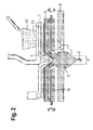
Fig.2 zeigt, wie das Zufrieren des Rohrendes vermieden wird. - Wenn der konusförmig erweiterte Abschnitt des Einkristalls kristallisiert wird, besteht die Gefahr, dass sich das konische Rohr im Bereich des Rohrendes durch fest werdendes Silizium zunehmend verengt, bis das Rohrende vollständig verschlossen ist. Die Folge davon ist, dass das Wachstum des Einkristalls zum Erliegen kommt, weil geschmolzenes Silizium durch das konische Rohr nicht mehr zur Verfügung gestellt werden kann und/oder weil sich geschmolzenes Silizium im konischen Rohr staut und schließlich mit der ersten, über der sich drehenden Platte aus Silizium angeordneten Induktionsheizspule in Kontakt kommt.
- Der Grund dafür wird von den Erfindern darin gesehen, dass der Außendurchmesser des Rohrendes des konischen Rohrs während einer kritischen Phase, in der der konusförmig erweiterte Abschnitt des Einkristalls einen Durchmesser von 15 bis 30 mm aufweist und kristallisiert wird, nicht hinreichend groß ist, um einen das Zufrieren vermeidenden Verlauf der Fest/Flüssig Phasengrenze zwischen dem Rohrende und der Schmelze zu ermöglichen. Erfindungsgemäß wird ein solcher Verlauf der Phasengrenze sichergestellt, indem mit Hilfe der unter der Platte angeordneten Induktionsheizspule das Rohr vom Rohrende aus soweit geschmolzen wird, dass der Außendurchmesser des Rohrendes während der kritischen Phase nicht kleiner als 15 mm ist.
-
Fig. 1 zeigt den kristallisierenden, konusförmig erweiterten Abschnitt 1 des Einkristalls und einen Teil des zuvor kristallisierten Dünnhalses 2. Das weitere Kristallwachstum wird genährt durch die, auf dem konusförmig erweiterten Abschnitt liegende Schmelze 3 aus Silizium und durch den Film 4 aus geschmolzenem Silizium, der an der Innenwand des konischen Rohrs 6 der Platte 5 aus Silizium zur Schmelze 3 fließt. Der Film wird von der über der Platte angeordneten, ersten Induktionsheizspule 7 durch Anschmelzen der Plattenoberfläche erzeugt und flüssig gehalten. Zu einem späteren Zeitpunkt wird diese Induktionsheizspule 7 auch eingesetzt, um Granulat 13 aus Silizium, das durch einen Trichter 12 auf die Platte 5 gefördert wird, induktiv zu schmelzen. Der Film 4 wird dann hauptsächlich von geschmolzenem Granulat gebildet. Die Induktionsheizspule 7 hat vorzugsweise die Merkmale der in derDE 10 2008 013 326 A1 beschriebenen Induktionsheizspule. Die untere Seite der Platte 5 wird gekühlt, beispielsweise durch eine Kühlvorrichtung 10. Die zweite, unter der Platte 5 aus Silizium angeordnete Induktionsheizspule 8 wird hauptsächlich in gleicher Weise wie beim FZ-Verfahren betrieben, zunächst um den, bis zu einem Enddurchmesser konusförmig erweiterten Abschnitt 1 und danach um den Abschnitt des Einkristalls mit gleich bleibendem Soll-Durchmesser kontrolliert zu kristallisieren. - Während der kritischen Phase, wenn der Durchmesser des konusförmig erweiterten Abschnitts 1 des Einkristalls auf 15 bis 30 mm angewachsen ist und der Außendurchmesser D des Rohrendes des konusförmigen Rohrs 6 kleiner als 15 mm ist oder wird, besteht eine hohe Wahrscheinlichkeit, dass das konusförmige Rohr 6 am Rohrende zufriert. Je kleiner der Außendurchmesser D ist, desto steiler fällt die Fest/Flüssig-Phasengrenze 9 vom Tripelpunkt T am äußeren Rand des Rohrendes des konischen Rohrs 6 nach innen. Wegen des Gefälles tendiert der Tripelpunkt T dazu, sich entlang der Phasengrenze 9 nach innen zu verschieben. Infolgedessen wird der Abstand zwischen der Schmelze 3 und der zweiten Induktionsheizspule 8 größer, wodurch weniger Energie auf die Schmelze 3 übertragen wird und die Schmelze 3 am Rohrende des konischen Rohrs 6 festzufrieren droht. Das Verringern des Abstands zwischen Induktionsheizspule 8 und Schmelze 3 oder eine Erhöhung der Heizleistung der Induktionsheizspule 8 schafft in dieser Situation keine Abhilfe mehr. Derartige Maßnahmen fördern sogar die zunehmende Verengung des Rohrendes, weil der elektromagnetische Druck die Schmelze 3 und den Tripelpunkt T dann noch weiter nach innen drückt.
- Um zuverlässig zu vermeiden, dass der beschriebene Mechanismus abläuft, wird mit Hilfe der unter der Platte 5 angeordneten Induktionsheizspule 8 das konusförmige Rohr 6 vom Rohrende aus soweit geschmolzen, dass der Außendurchmesser D des Rohrendes während der kritischen Phase nicht kleiner als 15 mm ist. Dadurch erreicht man einen Verlauf der Fest/Flüssig-Phasengrenze, wie er in
Fig.2 dargestellt ist. Die Fest/Flüssig-Phasengrenze steigt vom Tripelpunkt T am äußeren Rand des Rohrendes des konusförmigen Rohrs 6 nach innen an. Die Steigung reicht aus, dass der Tripelpunkt T stabil am äußeren Rand des Rohrendes des konischen Rohrs 6 bleibt, und der Abstand zwischen der zweiten Induktionsheizspule 8 und der Schmelze 3 nicht größer wird. - Der Durchmesser des Innenlochs 11 der zweiten Induktionsheizspule 8 ist größer als der Durchmesser der Schmelze 3 und beträgt vorzugsweise mehr als 30 mm und nicht mehr als 40 mm. Das Verhältnis des Außendurchmessers des Rohrendes des konusförmigen Rohrs 6 und des Durchmessers des Innenlochs 11 ist während der kritischen Phase vorzugsweise 1:3 oder größer, besonders bevorzugt 1:3 bis 4:5.
- Ist der konusförmig erweiterte Abschnitt 1 bereits auf einen Durchmesser von mehr als 30 mm angewachsen, reicht die Menge an zur Schmelze nachfließendem, geschmolzenem Silizium in der Regel aus, um zu verhindern, dass das Rohrende des konischen Rohrs 6 zufriert, auch wenn der Außendurchmesser D des Rohrendes des konischen Rohrs unter 15 mm fällt.
- Es wurde eine Reihe von Einkristallen aus Silizium mit einem Durchmesser von 100 mm durch Umschmelzen von Granulat produziert. Die nachfolgende Tabelle zeigt die Anzahl der Ansetzversuche an, die durchschnittlich notwendig waren, um einen Einkristall erfolgreich herzustellen, und zwar in Abhängigkeit des Außendurchmessers des Rohrendes des konischen Rohrs im Zeitraum zwischen dem Erreichen eines Durchmessers des konusförmig erweiterten Abschnitts von 15 mm und dem Erreichen eines Durchmessers von 30 mm.
Außendurchmesser des Rohrendes Ansetzversuche weniger als 15 mm 4 15 mm und größer 1
Claims (2)
- Verfahren zur Herstellung eines Einkristalls aus Silizium durch Umschmelzen von Granulat, umfassend
das Kristallisieren eines konusförmig erweiterten Abschnitts des Einkristalls mit Hilfe einer Induktionsheizspule, die unter einer sich drehenden Platte aus Silizium angeordnet ist; und das Zuführen von induktiv geschmolzenem Silizium durch ein konisches Rohr der Platte, das eine zentrale Öffnung der Platte umschließt und sich unter die Platte erstreckt, zu einer Schmelze, die sich auf dem konusförmig erweiterten Abschnitt des Einkristalls befindet und die Kontakt zu einem Rohrende des konischen Rohrs hat, wobei mit Hilfe der unter der Platte angeordneten Induktionsheizspule ausreichend Energie bereitgestellt wird, damit der Außendurchmesser des Rohrendes nicht kleiner als 15 mm ist, solange der konusförmig erweiterte Abschnitt des Einkristalls einen Durchmesser von 15 bis 30 mm aufweist und kristallisiert wird. - Verfahren nach Anspruch 1, wobei mit Hilfe der unter der Platte angeordneten Induktionsheizspule ausreichend Energie bereitgestellt wird, damit das Verhältnis des Außendurchmessers des Rohrendes und des Durchmessers eines Innenlochs der Induktionsheizspule 1:3 oder größer ist, solange der konusförmig erweiterte Abschnitt des Einkristalls einen Durchmesser von 15 bis 30 mm aufweist und kristallisiert wird.
Applications Claiming Priority (1)
| Application Number | Priority Date | Filing Date | Title |
|---|---|---|---|
| DE102009052745A DE102009052745A1 (de) | 2009-11-11 | 2009-11-11 | Verfahren zur Herstellung eines Einkristalls aus Silizium durch Umschmelzen von Granulat |
Publications (2)
| Publication Number | Publication Date |
|---|---|
| EP2322695A1 true EP2322695A1 (de) | 2011-05-18 |
| EP2322695B1 EP2322695B1 (de) | 2011-11-23 |
Family
ID=43128203
Family Applications (1)
| Application Number | Title | Priority Date | Filing Date |
|---|---|---|---|
| EP10188864A Not-in-force EP2322695B1 (de) | 2009-11-11 | 2010-10-26 | Verfahren zur Herstellung eines Einkristalls aus Silizium durch Umschmelzen von Granulat |
Country Status (10)
| Country | Link |
|---|---|
| US (1) | US8834627B2 (de) |
| EP (1) | EP2322695B1 (de) |
| JP (1) | JP5183719B2 (de) |
| KR (1) | KR101294453B1 (de) |
| CN (1) | CN102061512B (de) |
| AT (1) | ATE534758T1 (de) |
| DE (1) | DE102009052745A1 (de) |
| DK (1) | DK2322695T3 (de) |
| SG (2) | SG171511A1 (de) |
| TW (1) | TWI424101B (de) |
Families Citing this family (5)
| Publication number | Priority date | Publication date | Assignee | Title |
|---|---|---|---|---|
| DE102012215677B3 (de) * | 2012-09-04 | 2013-10-10 | Siltronic Ag | Verfahren zum Herstellen eines Einkristalls aus Silizium |
| DE102014207149A1 (de) * | 2014-04-14 | 2015-10-29 | Siltronic Ag | Vorrichtung und Verfahren zur Herstellung eines Einkristalls aus Silizium |
| DE102014210936B3 (de) * | 2014-06-06 | 2015-10-22 | Siltronic Ag | Vorrichtung und Verfahren zur Herstellung eines Kristalls aus Halbleitermaterial |
| DE102017202420A1 (de) | 2017-02-15 | 2018-08-16 | Siltronic Ag | Verfahren und Anlage zum Ziehen eines Einkristalls nach dem FZ-Verfahren |
| CN116288650B (zh) * | 2023-05-24 | 2023-08-29 | 苏州晨晖智能设备有限公司 | 以颗粒硅为原料的硅单晶生长装置和生长方法 |
Citations (2)
| Publication number | Priority date | Publication date | Assignee | Title |
|---|---|---|---|---|
| DE10204178A1 (de) | 2002-02-01 | 2003-09-04 | Wacker Siltronic Halbleitermat | Verfahren und Vorrichtung zum Herstellen eines Einkristalls aus Halbleitermaterial |
| DE102008013326A1 (de) | 2008-03-10 | 2009-09-17 | Siltronic Ag | Induktionsheizspule und Verfahren zum Schmelzen von Granulat aus Halbleitermaterial |
Family Cites Families (7)
| Publication number | Priority date | Publication date | Assignee | Title |
|---|---|---|---|---|
| US5108720A (en) * | 1991-05-20 | 1992-04-28 | Hemlock Semiconductor Corporation | Float zone processing of particulate silicon |
| JP3053958B2 (ja) * | 1992-04-10 | 2000-06-19 | 光弘 丸山 | 浮遊帯溶融法による結晶の製造装置 |
| DE19538020A1 (de) * | 1995-10-12 | 1997-04-17 | Wacker Siltronic Halbleitermat | Verfahren und Vorrichtung zur Herstellung von Einkristallen aus Silicium |
| JP3644227B2 (ja) | 1997-12-22 | 2005-04-27 | 信越半導体株式会社 | シリコン単結晶の製造方法及び製造装置 |
| JPH11292682A (ja) * | 1998-04-02 | 1999-10-26 | Shin Etsu Handotai Co Ltd | シリコン単結晶の製造方法および製造装置 |
| TWM246495U (en) * | 2003-10-31 | 2004-10-11 | Hon Hai Prec Ind Co Ltd | Automatic apparatus for assembling bearig to motor |
| CA2795395C (en) * | 2010-04-13 | 2018-05-29 | Schmid Silicon Technology Gmbh | Production of monocrystalline semiconductor materials |
-
2009
- 2009-11-11 DE DE102009052745A patent/DE102009052745A1/de not_active Withdrawn
-
2010
- 2010-09-15 SG SG201006688-4A patent/SG171511A1/en unknown
- 2010-09-15 SG SG2013024112A patent/SG189726A1/en unknown
- 2010-09-21 CN CN201010294175XA patent/CN102061512B/zh not_active Expired - Fee Related
- 2010-10-20 TW TW099135735A patent/TWI424101B/zh not_active IP Right Cessation
- 2010-10-26 EP EP10188864A patent/EP2322695B1/de not_active Not-in-force
- 2010-10-26 AT AT10188864T patent/ATE534758T1/de active
- 2010-10-26 DK DK10188864.2T patent/DK2322695T3/da active
- 2010-10-28 US US12/913,970 patent/US8834627B2/en not_active Expired - Fee Related
- 2010-11-10 KR KR1020100111530A patent/KR101294453B1/ko not_active Expired - Fee Related
- 2010-11-11 JP JP2010253104A patent/JP5183719B2/ja not_active Expired - Fee Related
Patent Citations (2)
| Publication number | Priority date | Publication date | Assignee | Title |
|---|---|---|---|---|
| DE10204178A1 (de) | 2002-02-01 | 2003-09-04 | Wacker Siltronic Halbleitermat | Verfahren und Vorrichtung zum Herstellen eines Einkristalls aus Halbleitermaterial |
| DE102008013326A1 (de) | 2008-03-10 | 2009-09-17 | Siltronic Ag | Induktionsheizspule und Verfahren zum Schmelzen von Granulat aus Halbleitermaterial |
Also Published As
| Publication number | Publication date |
|---|---|
| JP5183719B2 (ja) | 2013-04-17 |
| JP2011102234A (ja) | 2011-05-26 |
| TWI424101B (zh) | 2014-01-21 |
| KR101294453B1 (ko) | 2013-08-07 |
| US8834627B2 (en) | 2014-09-16 |
| EP2322695B1 (de) | 2011-11-23 |
| ATE534758T1 (de) | 2011-12-15 |
| CN102061512A (zh) | 2011-05-18 |
| DK2322695T3 (da) | 2012-02-27 |
| TW201132810A (en) | 2011-10-01 |
| KR20110052501A (ko) | 2011-05-18 |
| DE102009052745A1 (de) | 2011-05-12 |
| US20110107960A1 (en) | 2011-05-12 |
| CN102061512B (zh) | 2013-12-11 |
| SG189726A1 (en) | 2013-05-31 |
| SG171511A1 (en) | 2011-06-29 |
Similar Documents
| Publication | Publication Date | Title |
|---|---|---|
| EP2354278B1 (de) | Verfahren zur Herstellung eines Einkristalls aus Silizium unter Verwendung von geschmolzenem Granulat | |
| EP2322695B1 (de) | Verfahren zur Herstellung eines Einkristalls aus Silizium durch Umschmelzen von Granulat | |
| DE2633961C2 (de) | Verfahren zum Ziehen eines dünnen Halbleiter-Einkristallbandes | |
| EP2319961B1 (de) | Vorrichtung zur Herstellung eines Einkristalls aus Silizium durch Umschmelzen von Granulat | |
| DE112015005768B4 (de) | Verfahren zur Herstellung von Monokristall | |
| DE10137856B4 (de) | Durch tiegelloses Zonenziehen hergestellter Einkristall aus Silicium | |
| DE2059713A1 (de) | Verfahren und Vorrichtung zum Herstellen von Halbleiter-Einkristallen nach der Czochralski-Methode | |
| DE112013006489B4 (de) | Einkristallblock, Vorrichtungen und Verfahren zur Herstellung desselben | |
| DE10204178B4 (de) | Verfahren und Vorrichtung zum Herstellen eines Einkristalls aus Halbleitermaterial | |
| DE2219687A1 (de) | Vorrichtung zum Herstellen und Wachstum eines kristallinen Stoffes | |
| DE102011087759B4 (de) | Verfahren zur Herstellung von Silizium-Ingots und Silizium-Ingot | |
| DE102008038810B4 (de) | Verfahren und Vorrichtung zur Herstellung eines Einkristalls aus Halbleitermaterial | |
| DE60017324T2 (de) | Verfahren zur Kristallzüchtung | |
| EP1038995B1 (de) | Verfahren und Vorrichtung zur Herstellung von Einkristallen | |
| DE3785638T2 (de) | Verfahren zur Züchtung von Kristallen aus Halbleiterverbindungen. | |
| EP2703525B1 (de) | Verfahren zum Herstellen eines Einkristalls aus Silizium | |
| DE102006052961B4 (de) | Verfahren zur Herstellung eines Halbleiterkristalls | |
| DE2234512C3 (de) | Verfahren zum Herstellen von (Umorientierten Halbleitereinkristallstäben mit zur Stabmitte abtauendem spezifischem Widerstand | |
| DE3210827C2 (de) | Verfahren zum Züchten eines III/V-Verbindungs-Einkristalls | |
| DE69016392T2 (de) | Verfahren und Vorrichtung zur Züchtung von Kristallen. | |
| DE102006055376B4 (de) | Verfahren zur Herstellung eines Silizium-Halbleiterkristalls | |
| DE102004042343B4 (de) | Verfahren und Vorrichtung zur Modifikation von amorphen Halbleitern mittels Laserstrahlung | |
| DE60017077T2 (de) | Elektro-Schlacke-Umschmelzsysteme mit Bodenausguss und kontrolliertem Elektrostrompfad | |
| DE102017217022A1 (de) | Verfahren zur Herstellung von Kristallmaterialien | |
| DE1519908A1 (de) | Vorrichtung zum Herstellen eines kristallinen Stabes durch tiegelfreies Zonenschmelzen |
Legal Events
| Date | Code | Title | Description |
|---|---|---|---|
| PUAI | Public reference made under article 153(3) epc to a published international application that has entered the european phase |
Free format text: ORIGINAL CODE: 0009012 |
|
| 17P | Request for examination filed |
Effective date: 20101026 |
|
| AK | Designated contracting states |
Kind code of ref document: A1 Designated state(s): AL AT BE BG CH CY CZ DE DK EE ES FI FR GB GR HR HU IE IS IT LI LT LU LV MC MK MT NL NO PL PT RO RS SE SI SK SM TR |
|
| AX | Request for extension of the european patent |
Extension state: BA ME |
|
| GRAP | Despatch of communication of intention to grant a patent |
Free format text: ORIGINAL CODE: EPIDOSNIGR1 |
|
| RIC1 | Information provided on ipc code assigned before grant |
Ipc: C30B 13/20 20060101ALI20110606BHEP Ipc: C30B 13/26 20060101ALI20110606BHEP Ipc: C30B 13/00 20060101AFI20110606BHEP |
|
| RTI1 | Title (correction) |
Free format text: METHOD FOR PRODUCING A SINGLE CRYSTAL OF SILICON BY REMELTING GRANULES |
|
| GRAS | Grant fee paid |
Free format text: ORIGINAL CODE: EPIDOSNIGR3 |
|
| GRAA | (expected) grant |
Free format text: ORIGINAL CODE: 0009210 |
|
| AK | Designated contracting states |
Kind code of ref document: B1 Designated state(s): AL AT BE BG CH CY CZ DE DK EE ES FI FR GB GR HR HU IE IS IT LI LT LU LV MC MK MT NL NO PL PT RO RS SE SI SK SM TR |
|
| REG | Reference to a national code |
Ref country code: GB Ref legal event code: FG4D Free format text: NOT ENGLISH |
|
| REG | Reference to a national code |
Ref country code: CH Ref legal event code: EP |
|
| REG | Reference to a national code |
Ref country code: IE Ref legal event code: FG4D Free format text: LANGUAGE OF EP DOCUMENT: GERMAN |
|
| REG | Reference to a national code |
Ref country code: DE Ref legal event code: R096 Ref document number: 502010000242 Country of ref document: DE Effective date: 20120202 |
|
| REG | Reference to a national code |
Ref country code: DK Ref legal event code: T3 |
|
| REG | Reference to a national code |
Ref country code: NL Ref legal event code: VDEP Effective date: 20111123 |
|
| LTIE | Lt: invalidation of european patent or patent extension |
Effective date: 20111123 |
|
| PG25 | Lapsed in a contracting state [announced via postgrant information from national office to epo] |
Ref country code: LT Free format text: LAPSE BECAUSE OF FAILURE TO SUBMIT A TRANSLATION OF THE DESCRIPTION OR TO PAY THE FEE WITHIN THE PRESCRIBED TIME-LIMIT Effective date: 20111123 Ref country code: IS Free format text: LAPSE BECAUSE OF FAILURE TO SUBMIT A TRANSLATION OF THE DESCRIPTION OR TO PAY THE FEE WITHIN THE PRESCRIBED TIME-LIMIT Effective date: 20120323 Ref country code: NO Free format text: LAPSE BECAUSE OF FAILURE TO SUBMIT A TRANSLATION OF THE DESCRIPTION OR TO PAY THE FEE WITHIN THE PRESCRIBED TIME-LIMIT Effective date: 20120223 |
|
| PG25 | Lapsed in a contracting state [announced via postgrant information from national office to epo] |
Ref country code: PT Free format text: LAPSE BECAUSE OF FAILURE TO SUBMIT A TRANSLATION OF THE DESCRIPTION OR TO PAY THE FEE WITHIN THE PRESCRIBED TIME-LIMIT Effective date: 20120323 Ref country code: SE Free format text: LAPSE BECAUSE OF FAILURE TO SUBMIT A TRANSLATION OF THE DESCRIPTION OR TO PAY THE FEE WITHIN THE PRESCRIBED TIME-LIMIT Effective date: 20111123 Ref country code: GR Free format text: LAPSE BECAUSE OF FAILURE TO SUBMIT A TRANSLATION OF THE DESCRIPTION OR TO PAY THE FEE WITHIN THE PRESCRIBED TIME-LIMIT Effective date: 20120224 Ref country code: NL Free format text: LAPSE BECAUSE OF FAILURE TO SUBMIT A TRANSLATION OF THE DESCRIPTION OR TO PAY THE FEE WITHIN THE PRESCRIBED TIME-LIMIT Effective date: 20111123 Ref country code: LV Free format text: LAPSE BECAUSE OF FAILURE TO SUBMIT A TRANSLATION OF THE DESCRIPTION OR TO PAY THE FEE WITHIN THE PRESCRIBED TIME-LIMIT Effective date: 20111123 Ref country code: HR Free format text: LAPSE BECAUSE OF FAILURE TO SUBMIT A TRANSLATION OF THE DESCRIPTION OR TO PAY THE FEE WITHIN THE PRESCRIBED TIME-LIMIT Effective date: 20111123 Ref country code: SI Free format text: LAPSE BECAUSE OF FAILURE TO SUBMIT A TRANSLATION OF THE DESCRIPTION OR TO PAY THE FEE WITHIN THE PRESCRIBED TIME-LIMIT Effective date: 20111123 |
|
| REG | Reference to a national code |
Ref country code: IE Ref legal event code: FD4D |
|
| PG25 | Lapsed in a contracting state [announced via postgrant information from national office to epo] |
Ref country code: RS Free format text: LAPSE BECAUSE OF FAILURE TO SUBMIT A TRANSLATION OF THE DESCRIPTION OR TO PAY THE FEE WITHIN THE PRESCRIBED TIME-LIMIT Effective date: 20111123 Ref country code: CY Free format text: LAPSE BECAUSE OF FAILURE TO SUBMIT A TRANSLATION OF THE DESCRIPTION OR TO PAY THE FEE WITHIN THE PRESCRIBED TIME-LIMIT Effective date: 20111123 |
|
| PG25 | Lapsed in a contracting state [announced via postgrant information from national office to epo] |
Ref country code: EE Free format text: LAPSE BECAUSE OF FAILURE TO SUBMIT A TRANSLATION OF THE DESCRIPTION OR TO PAY THE FEE WITHIN THE PRESCRIBED TIME-LIMIT Effective date: 20111123 Ref country code: SK Free format text: LAPSE BECAUSE OF FAILURE TO SUBMIT A TRANSLATION OF THE DESCRIPTION OR TO PAY THE FEE WITHIN THE PRESCRIBED TIME-LIMIT Effective date: 20111123 Ref country code: BG Free format text: LAPSE BECAUSE OF FAILURE TO SUBMIT A TRANSLATION OF THE DESCRIPTION OR TO PAY THE FEE WITHIN THE PRESCRIBED TIME-LIMIT Effective date: 20120223 Ref country code: IE Free format text: LAPSE BECAUSE OF FAILURE TO SUBMIT A TRANSLATION OF THE DESCRIPTION OR TO PAY THE FEE WITHIN THE PRESCRIBED TIME-LIMIT Effective date: 20111123 Ref country code: CZ Free format text: LAPSE BECAUSE OF FAILURE TO SUBMIT A TRANSLATION OF THE DESCRIPTION OR TO PAY THE FEE WITHIN THE PRESCRIBED TIME-LIMIT Effective date: 20111123 |
|
| PG25 | Lapsed in a contracting state [announced via postgrant information from national office to epo] |
Ref country code: PL Free format text: LAPSE BECAUSE OF FAILURE TO SUBMIT A TRANSLATION OF THE DESCRIPTION OR TO PAY THE FEE WITHIN THE PRESCRIBED TIME-LIMIT Effective date: 20111123 Ref country code: IT Free format text: LAPSE BECAUSE OF FAILURE TO SUBMIT A TRANSLATION OF THE DESCRIPTION OR TO PAY THE FEE WITHIN THE PRESCRIBED TIME-LIMIT Effective date: 20111123 Ref country code: RO Free format text: LAPSE BECAUSE OF FAILURE TO SUBMIT A TRANSLATION OF THE DESCRIPTION OR TO PAY THE FEE WITHIN THE PRESCRIBED TIME-LIMIT Effective date: 20111123 |
|
| PLBE | No opposition filed within time limit |
Free format text: ORIGINAL CODE: 0009261 |
|
| STAA | Information on the status of an ep patent application or granted ep patent |
Free format text: STATUS: NO OPPOSITION FILED WITHIN TIME LIMIT |
|
| 26N | No opposition filed |
Effective date: 20120824 |
|
| REG | Reference to a national code |
Ref country code: DE Ref legal event code: R097 Ref document number: 502010000242 Country of ref document: DE Effective date: 20120824 |
|
| BERE | Be: lapsed |
Owner name: SILTRONIC A.G. Effective date: 20121031 |
|
| PG25 | Lapsed in a contracting state [announced via postgrant information from national office to epo] |
Ref country code: ES Free format text: LAPSE BECAUSE OF FAILURE TO SUBMIT A TRANSLATION OF THE DESCRIPTION OR TO PAY THE FEE WITHIN THE PRESCRIBED TIME-LIMIT Effective date: 20120305 |
|
| PG25 | Lapsed in a contracting state [announced via postgrant information from national office to epo] |
Ref country code: MC Free format text: LAPSE BECAUSE OF NON-PAYMENT OF DUE FEES Effective date: 20121031 |
|
| PG25 | Lapsed in a contracting state [announced via postgrant information from national office to epo] |
Ref country code: FI Free format text: LAPSE BECAUSE OF FAILURE TO SUBMIT A TRANSLATION OF THE DESCRIPTION OR TO PAY THE FEE WITHIN THE PRESCRIBED TIME-LIMIT Effective date: 20111123 |
|
| REG | Reference to a national code |
Ref country code: FR Ref legal event code: ST Effective date: 20130628 |
|
| PG25 | Lapsed in a contracting state [announced via postgrant information from national office to epo] |
Ref country code: BE Free format text: LAPSE BECAUSE OF NON-PAYMENT OF DUE FEES Effective date: 20121031 |
|
| PG25 | Lapsed in a contracting state [announced via postgrant information from national office to epo] |
Ref country code: FR Free format text: LAPSE BECAUSE OF NON-PAYMENT OF DUE FEES Effective date: 20121031 |
|
| PG25 | Lapsed in a contracting state [announced via postgrant information from national office to epo] |
Ref country code: AL Free format text: LAPSE BECAUSE OF FAILURE TO SUBMIT A TRANSLATION OF THE DESCRIPTION OR TO PAY THE FEE WITHIN THE PRESCRIBED TIME-LIMIT Effective date: 20111123 Ref country code: MT Free format text: LAPSE BECAUSE OF FAILURE TO SUBMIT A TRANSLATION OF THE DESCRIPTION OR TO PAY THE FEE WITHIN THE PRESCRIBED TIME-LIMIT Effective date: 20111123 |
|
| PG25 | Lapsed in a contracting state [announced via postgrant information from national office to epo] |
Ref country code: TR Free format text: LAPSE BECAUSE OF FAILURE TO SUBMIT A TRANSLATION OF THE DESCRIPTION OR TO PAY THE FEE WITHIN THE PRESCRIBED TIME-LIMIT Effective date: 20111123 |
|
| PG25 | Lapsed in a contracting state [announced via postgrant information from national office to epo] |
Ref country code: LU Free format text: LAPSE BECAUSE OF NON-PAYMENT OF DUE FEES Effective date: 20121026 Ref country code: SM Free format text: LAPSE BECAUSE OF FAILURE TO SUBMIT A TRANSLATION OF THE DESCRIPTION OR TO PAY THE FEE WITHIN THE PRESCRIBED TIME-LIMIT Effective date: 20111123 |
|
| PG25 | Lapsed in a contracting state [announced via postgrant information from national office to epo] |
Ref country code: HU Free format text: LAPSE BECAUSE OF FAILURE TO SUBMIT A TRANSLATION OF THE DESCRIPTION OR TO PAY THE FEE WITHIN THE PRESCRIBED TIME-LIMIT Effective date: 20101026 |
|
| REG | Reference to a national code |
Ref country code: CH Ref legal event code: PL |
|
| GBPC | Gb: european patent ceased through non-payment of renewal fee |
Effective date: 20141026 |
|
| PG25 | Lapsed in a contracting state [announced via postgrant information from national office to epo] |
Ref country code: MK Free format text: LAPSE BECAUSE OF FAILURE TO SUBMIT A TRANSLATION OF THE DESCRIPTION OR TO PAY THE FEE WITHIN THE PRESCRIBED TIME-LIMIT Effective date: 20111123 Ref country code: GB Free format text: LAPSE BECAUSE OF NON-PAYMENT OF DUE FEES Effective date: 20141026 Ref country code: LI Free format text: LAPSE BECAUSE OF NON-PAYMENT OF DUE FEES Effective date: 20141031 Ref country code: CH Free format text: LAPSE BECAUSE OF NON-PAYMENT OF DUE FEES Effective date: 20141031 |
|
| REG | Reference to a national code |
Ref country code: AT Ref legal event code: MM01 Ref document number: 534758 Country of ref document: AT Kind code of ref document: T Effective date: 20151026 |
|
| PG25 | Lapsed in a contracting state [announced via postgrant information from national office to epo] |
Ref country code: AT Free format text: LAPSE BECAUSE OF NON-PAYMENT OF DUE FEES Effective date: 20151026 |
|
| PGFP | Annual fee paid to national office [announced via postgrant information from national office to epo] |
Ref country code: DE Payment date: 20191021 Year of fee payment: 10 |
|
| PGFP | Annual fee paid to national office [announced via postgrant information from national office to epo] |
Ref country code: DK Payment date: 20191023 Year of fee payment: 10 |
|
| REG | Reference to a national code |
Ref country code: DE Ref legal event code: R119 Ref document number: 502010000242 Country of ref document: DE |
|
| REG | Reference to a national code |
Ref country code: DK Ref legal event code: EBP Effective date: 20201031 |
|
| PG25 | Lapsed in a contracting state [announced via postgrant information from national office to epo] |
Ref country code: DE Free format text: LAPSE BECAUSE OF NON-PAYMENT OF DUE FEES Effective date: 20210501 |
|
| PG25 | Lapsed in a contracting state [announced via postgrant information from national office to epo] |
Ref country code: DK Free format text: LAPSE BECAUSE OF NON-PAYMENT OF DUE FEES Effective date: 20201031 |