EP2321190B1 - Deckelbehälter - Google Patents
Deckelbehälter Download PDFInfo
- Publication number
- EP2321190B1 EP2321190B1 EP09777703A EP09777703A EP2321190B1 EP 2321190 B1 EP2321190 B1 EP 2321190B1 EP 09777703 A EP09777703 A EP 09777703A EP 09777703 A EP09777703 A EP 09777703A EP 2321190 B1 EP2321190 B1 EP 2321190B1
- Authority
- EP
- European Patent Office
- Prior art keywords
- container
- lid
- liner
- liquid
- lidded
- Prior art date
- Legal status (The legal status is an assumption and is not a legal conclusion. Google has not performed a legal analysis and makes no representation as to the accuracy of the status listed.)
- Active
Links
Images


Classifications
-
- B—PERFORMING OPERATIONS; TRANSPORTING
- B65—CONVEYING; PACKING; STORING; HANDLING THIN OR FILAMENTARY MATERIAL
- B65D—CONTAINERS FOR STORAGE OR TRANSPORT OF ARTICLES OR MATERIALS, e.g. BAGS, BARRELS, BOTTLES, BOXES, CANS, CARTONS, CRATES, DRUMS, JARS, TANKS, HOPPERS, FORWARDING CONTAINERS; ACCESSORIES, CLOSURES, OR FITTINGS THEREFOR; PACKAGING ELEMENTS; PACKAGES
- B65D25/00—Details of other kinds or types of rigid or semi-rigid containers
- B65D25/14—Linings or internal coatings
- B65D25/16—Loose, or loosely-attached, linings
-
- B—PERFORMING OPERATIONS; TRANSPORTING
- B65—CONVEYING; PACKING; STORING; HANDLING THIN OR FILAMENTARY MATERIAL
- B65D—CONTAINERS FOR STORAGE OR TRANSPORT OF ARTICLES OR MATERIALS, e.g. BAGS, BARRELS, BOTTLES, BOXES, CANS, CARTONS, CRATES, DRUMS, JARS, TANKS, HOPPERS, FORWARDING CONTAINERS; ACCESSORIES, CLOSURES, OR FITTINGS THEREFOR; PACKAGING ELEMENTS; PACKAGES
- B65D77/00—Packages formed by enclosing articles or materials in preformed containers, e.g. boxes, cartons, sacks or bags
- B65D77/04—Articles or materials enclosed in two or more containers disposed one within another
- B65D77/06—Liquids or semi-liquids or other materials or articles enclosed in flexible containers disposed within rigid containers
Definitions
- the invention relates to a lid container for storage and transport of particularly dangerous liquid products, with an outer container body, with an upper container lid and a thin-walled inliner used.
- the container lid has at least one gas and liquid-tight sealable filling and emptying opening and z. B. by means of U-shaped clamping ring closure or without clamping ring as a snap lid by means of snap closure or as a screw cap by means of screw cap on the upper container opening of the container body to be fixed to a correspondingly formed flange edge.
- liquids especially dangerous liquids such as chemicals or the like are filled in steel or plastic bung casks.
- lidded drum Open Top Drum
- bung drum Closed Head Drum
- a lid container according to the preamble of entitlement 1 is known from DE-A1-39 08 099 known.
- the invention is based on the recognition that usual filled lidded container - even with inserted liners - only to a limited extent dangerous
- Liquids can be used because they are exposed in case of container crashes - especially in a critical diagonal case - in the connecting region of the outer container body and upper container lid high loads - especially in plastic lid drums with steel clamping ring closure - often lead to leaks and thus the application of Limit lidded drums to non-hazardous particulate or pasty contents.
- a completely closed container for receiving the liquid filling material which consists in terms of liquid tightness of the two essential parts inliner and container lid, which are inextricably gas- and liquid-tightly interconnected.
- the filling and emptying takes place exclusively via one or two small bung openings (eg 2 inch opening) in the container lid, which are closed by gas or liquid tight by means of appropriate screw cap or bung plug.
- the lower container body is in this case no longer directly involved in the sealing of the liquid filling material and has essentially only to fulfill a supporting function. Since the container body with the liquid product is no longer in contact, it is ideal for multiple use.
- the container body can be made of thermoplastic material (eg HD-PE) and can be produced by injection molding, by blow molding or by rotary molding.
- the container body may also be made of metal (eg steel sheet) or wound kraft paper (cardboard drum, fiber drum) consist.
- the lid container according to the invention now also resists considerably higher internal pressures than conventional lidded drums, as the liquid-tight seal to the container interior no longer has a sealing ring inserted at the outer circumference relative to the large-diameter container opening, but only at the substantially smaller bung closure Inch) or screw cap (eg 150 mm diameter) inside the container lid. Due to the significantly better tightness behavior is possible that higher-quality UN approvals - can be achieved - even for dangerous liquid products.
- Bung casks made of thermoplastic material have z.
- This is particularly critical for stacked bung barrels in terms of barrel crashes due to stacking.
- the plastic lidded drum according to the invention with welded inliner this disadvantageous effect no longer occurs because the clamping ring closure of barrel lid and barrel body is now just no longer gas and liquid tight, but the inliner can move easily after hot filling and compensate for a vacuum without this has an effect on the shape or shape and thus on the stack load capacity of the outer drum body and the drum lid.
- the container lid is made of thermoplastic material and is produced by injection molding or blow molding, and that the inliner in the outer peripheral region of the container lid insoluble gas-tight and liquid-tight welded or glued. If the liner and the container lid are both made of plastic, it is preferable to weld the inliner to each other on the edge of the container lid.
- drum body, drum cover and welded inliner equally made of thermoplastic material (HD-PE) the drum lid is fixed with laterally arranged in the cover disc bung opening by means of a steel clamping ring on the barrel body.
- This preferred embodiment is - provided with appropriate UN approval - as a substitute for normal plastic bung casks, usually for storage and the transport of dangerous liquid products are used.
- With multiple use of the cylindrical cover barrel body such a packaging unit is cheaper than a comparable bung barrel.
- the lid container according to the invention can also be used for solid, particulate or viscous, pasty products, as long as they can be sucked like liquids with a filling tube through the filling and emptying opening in the container lid and sucked out of the lid container by suction.
- the container lid has a downwardly open U-shaped edge with a vertical outer and a vertical inner cover flange, and that the inliner is externally welded or glued to the inner cover flange.
- the inliner is fixed in a vertical mounting area on the drum lid.
- the inner cover flange is formed extended and thereby provides a wider welding zone.
- the inliner has at its upper end an outwardly shaped edge in the manner of a radial flange, which is welded or glued in the opposite end face of the container mouth U-shaped lid edge.
- the attachment area is aligned more in the horizontal direction.
- the inliner edge extends into the contact surface of the drum lid and is there, so to speak, additionally pinched.
- this counteracts damaging tensile loads and prevents "rattling" of the drum lid, since conventional lid-sized sealing rings in the lid rim or on the mouth of the drum can be dispensed with in the lidding drum according to the invention.
- the inliner is usually formed as a cylindrical foil bag and made of thermoplastic material.
- the liquid-tight inliner for reinforcement can be equipped with a fabric insert.
- Reference numeral 10 designates a lid container according to the invention in a preferred embodiment as a fully cylindrical 220 liter lidded barrel, which shows a container body 12 with attached container lid 14 and clamping ring closure 16.
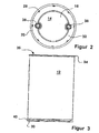
- the container lid 14 has a central flat cover disc 18 with therein, diametrically opposed bung openings and a U-shaped, downwardly open lid rim 20 with an outer ring piece 22 and an inner ring piece 24 ( Fig. 5 ).
- the central cover plate 18 is slightly raised compared to a flat, outer circumferential annular disc 32.
- a massively shaped circumferential bottom roll ring or foot ring 40 is arranged for better stability, and higher stability and Abrollles of the filled barrel in tilted oblique positioning.
- the clamping ring 16 engages with its upper leg the U-shaped lid edge 20 and with its lower leg a top of the container opening 36 on the outer wall of the container body 12 arranged substantially radially outwardly projecting Mantelflansch 34 and presses the container lid 14 to the container opening 36th ,
- FIG. 2 shows the barrel lid 14 in plan view.
- two opposing bung holes in the lid with 2-inch bung stopper 38 gas and liquid sealed.
- On the outside in the flat annular disc 32 and inside directly behind the U-shaped lid edge a plurality of stacking cams 28 are provided in the form of ring land sections. These stacking cams 28 are more similar when stacked
- Drums form fit in the inside behind the bottom roll ring 40 (foot ring) arranged engagement groove 30 and prevent z. As in transport shocks lateral slipping of stacked barrels.
- FIG. 3 is the container body or a barrel body 12 with upper filler opening 36, with upper shell flange 34 as a clamping ring abutment, and bottom-side foot ring 40 shown in cross-sectional view. Directly behind the foot ring 40, the engagement groove 30 is formed in the shallow barrel bottom.
- FIG. 4 shows the fully cylindrical lidded barrel 10 as a preferred embodiment of the invention with barrel body 12, with attached barrel lid 14 and welded to the barrel lid 14 plastic inliner 26.
- the lidded barrel has a capacity of about 220 liters and 55 US gallons. With a height of 890 mm and an outer diameter of 585 mm, it has almost the same dimensions as a corresponding steel drum and can be handled with the same steel barrel drum gripper tools.
- the drum lid 14 is made by injection molding of new plastic material (HD-PE virgin material).
- the inliner 26 is also made of new plastic material (HD-PE) and can be produced by injection molding, by deep-drawing or composite film material.
- the inliner 26 can be designed as a cylindrical film bag single-layered or multi-layered and thereby have a wall thickness of 0.6 to 2 mm and a weight of about 1.2 to 3.4 kg.
- a multilayer inliner is preferably provided with a barrier layer (permeation barrier) against migration of hydrocarbons, carbon dioxide or oxygen.
- the gas- and liquid-tight inliner 26 may further be provided for reinforcement with a fabric insert and against torsional security within the barrel body with oblique rolling a filled barrel with stiffening ribs extending in the vertical direction.
- the drum body 12 may be made by injection molding or blow molding and may be made of virgin plastic (HD-PE) or recycled plastics material. With a wall thickness of about 2.5 to 5 mm, the weight of the barrel body of about 5.0 to 9.5 kg can be. By a multiple use of the drum body, the packaging costs, the consumption of virgin material and thus the material costs can be advantageously reduced, and it reduces the amount of waste material from used packaging containers.
- the circle cutout "A" top left in Fig. 4 is in FIG. 5 shown as an enlarged partial cross-section. It can be seen that the inner ring piece 24 of the U-shaped lid rim 20 is formed extended so that it extends a whole distance in the container body opening 36 inside.
- the smooth outer surface of the annular web 24 as a mounting portion 42 for welding or gluing the inliner a height of about 35 mm (measured from the inside of the annular disc 32), on which the inliner welded to the inside of its upper edge region or is glued on.
- the welding or bonding takes place in at least one circumferential continuous line. It can also be provided two or more circumferential weld lines. If a plurality of weld lines are provided, preferably the bottom and top weld lines are linearly straight, while the or one of the center weld lines are also zigzag or wavy, so that a wider area at the top of the inliner is used for attachment Among other things, a better distribution of tensile forces is achieved. In particular, when gluing the liner in a wider circumferential, d. H. flat adhesive zone can be realized. Such an adhesive zone may be a height of about 5 mm to 40 mm, preferably about 15 mm.
- the weld region When welded with at least two circumferential weld lines, the weld region may extend over a height of 10 mm to 50 mm, preferably about 20 mm. With a wider attachment area of the inliner locally excessive tensile loads can be better distributed and collected on a larger surface area, so that overstretching of the liner and a tearing of the weld joint between inliner and cover is avoided.
- FIG. 6 the container mouth and the container lid version are shown again in detail. Due to the fact that the flat annular disc 32, which adjoins directly behind the U-shaped edge of the lid, is located approximately 15 to 20 mm lower than the upper end edge 32 of the U-shaped lid rim, there is a circumferential engagement groove for use or for handling a filled lid container with conventional drum gripper tools (parrot beak) as it is used for common steel drums.
- drum gripper tools parrot beak
- the inliner preferably has a thickened edge for better welding or gluing.
- the wall thickness can be formed to twice as thick as the normal wall thickness of the liner (about 0.5 to 2 mm).
- the inliner can be configured in various ways.
- the inliner 26 of a metal foil or a liquid-tight, with metal threads and plastic coated coated Fabric film exists.
- the liner 26 consists of a multilayer plastic film and a barrier layer against permeation (penetration) of hydrocarbons.
- circumferential sealing ring can be completely dispensed with the lidded barrel according to the invention, because the container lid 14 with closed clamping ring 16 does not have to be sealed gas- and liquid-tight on the upper mouth edge of the container opening, since already the drum lid with the welded inliner forms an absolutely liquid-tight unit. While usual, filled with liquid lidding drums usually leaking in container drops already fall heights of 1.2 m, the lid container according to the invention remains even with larger drop heights still completely liquid-tight, as long as the clamping ring does not jump completely.
- a liquid-tight lidded barrel is created in a simple manner, which is almost equal in performance to a closed one-piece bung barrel.
- the tightness of the lidded barrel according to the invention is substantially increased in case of container crashes and internal pressure loads, so that it is best suited for the use of liquid products and can even be approved for certain dangerous liquid contents.
- the barrel body which now only fulfills a purely protective function and no longer comes into contact with the contents and therefore has no adhering Golfgutreste after Golfgatetddling, can be reused many times in material and environmentally friendly manner.
Landscapes
- Engineering & Computer Science (AREA)
- Mechanical Engineering (AREA)
- Closures For Containers (AREA)
- Packages (AREA)
- Devices For Use In Laboratory Experiments (AREA)
- Packging For Living Organisms, Food Or Medicinal Products That Are Sensitive To Environmental Conditiond (AREA)
- Bag Frames (AREA)
- Table Devices Or Equipment (AREA)
Priority Applications (1)
| Application Number | Priority Date | Filing Date | Title |
|---|---|---|---|
| PL09777703T PL2321190T3 (pl) | 2008-08-08 | 2009-08-05 | Pojemnik z pokrywą |
Applications Claiming Priority (2)
| Application Number | Priority Date | Filing Date | Title |
|---|---|---|---|
| DE102008036988A DE102008036988A1 (de) | 2008-08-08 | 2008-08-08 | Deckelbehälter |
| PCT/EP2009/005703 WO2010015403A1 (de) | 2008-08-08 | 2009-08-05 | Deckelbehälter |
Publications (2)
| Publication Number | Publication Date |
|---|---|
| EP2321190A1 EP2321190A1 (de) | 2011-05-18 |
| EP2321190B1 true EP2321190B1 (de) | 2011-11-30 |
Family
ID=41082308
Family Applications (1)
| Application Number | Title | Priority Date | Filing Date |
|---|---|---|---|
| EP09777703A Active EP2321190B1 (de) | 2008-08-08 | 2009-08-05 | Deckelbehälter |
Country Status (12)
| Country | Link |
|---|---|
| US (1) | US20110266284A1 (https=) |
| EP (1) | EP2321190B1 (https=) |
| JP (1) | JP5362005B2 (https=) |
| AT (1) | ATE535459T1 (https=) |
| AU (1) | AU2009278205B2 (https=) |
| BR (1) | BRPI0917476B1 (https=) |
| DE (3) | DE102008036988A1 (https=) |
| ES (1) | ES2377287T3 (https=) |
| IL (1) | IL211035A (https=) |
| PL (1) | PL2321190T3 (https=) |
| WO (1) | WO2010015403A1 (https=) |
| ZA (1) | ZA201100993B (https=) |
Cited By (1)
| Publication number | Priority date | Publication date | Assignee | Title |
|---|---|---|---|---|
| CN103950609A (zh) * | 2014-05-08 | 2014-07-30 | 上海东富龙拓溥科技有限公司 | 一种配液系统人、手孔投料装置 |
Families Citing this family (5)
| Publication number | Priority date | Publication date | Assignee | Title |
|---|---|---|---|---|
| DE102008036988A1 (de) | 2008-08-08 | 2010-02-11 | Mauser-Werke Gmbh | Deckelbehälter |
| JP7479478B2 (ja) * | 2020-01-02 | 2024-05-08 | インテグリス・インコーポレーテッド | 鋼製オーバーパックを備えたバルク容器 |
| WO2021168566A1 (en) * | 2020-02-27 | 2021-09-02 | 9387-6670 Quebec Inc. | Double wall composite drum assembly and process for manufacturing same |
| DE102022210291A1 (de) | 2022-09-28 | 2024-03-28 | Saier Verpackungstechnik Gmbh & Co. Kg | Gebinde mit verriegelbarem Deckel |
| JP2025535178A (ja) * | 2022-10-24 | 2025-10-22 | シーディーエフ・コーポレーション | 容器 |
Family Cites Families (25)
| Publication number | Priority date | Publication date | Assignee | Title |
|---|---|---|---|---|
| US2226109A (en) * | 1936-12-14 | 1940-12-24 | Firestone Tire & Rubber Co | Metal container |
| DE1009101B (de) | 1953-10-23 | 1957-05-23 | Stebler Saner Metallwarenfabri | Randausbildung fuer Behaelter mit abnehmbarem, eine Innenauskleidung, vorzugsweise als Folie aus Polyaethylen, aufweisendem Deckel |
| US3167210A (en) * | 1963-04-30 | 1965-01-26 | Greig Bros Cooperage Corp | Device for securing the filler neck of a container liner to the container |
| SE342422B (https=) * | 1967-01-18 | 1972-02-07 | Rigello Pak Ab | |
| US3450254A (en) * | 1967-04-05 | 1969-06-17 | Colgate Palmolive Co | Package and receptacle |
| US3432070A (en) * | 1967-08-16 | 1969-03-11 | Greif Bros Cooperage Corp | Drum liner with flexible neck |
| US4164304A (en) * | 1978-05-30 | 1979-08-14 | The Continental Group, Inc. | Closure for steel drums with blow molded liners |
| JPS57127899A (en) * | 1981-02-02 | 1982-08-09 | Hitachi Ltd | Sealed container and sealing thereof |
| US4674650A (en) * | 1985-10-07 | 1987-06-23 | E. I. Du Pont De Nemours And Company | Container and cover fastening means |
| US4925055A (en) * | 1988-03-04 | 1990-05-15 | Edward S. Robbins, III | Container with unitary bladder and associated dispenser cap |
| DE3908099A1 (de) * | 1989-03-13 | 1990-09-27 | Schuetz Werke Gmbh Co Kg | Fass |
| DE4007617A1 (de) | 1990-03-11 | 1991-09-12 | Bernd Buedenbender | Mit einer auskleidung versehener mit spunden ausgestatteter behaelter |
| US5217138A (en) * | 1991-02-25 | 1993-06-08 | Hoover Group, Inc. | Liquid transport drum with removable liner |
| CA2051139C (en) | 1991-02-25 | 1995-10-17 | Dwight Ellis Nichols | Liquid transport drum with removable liner |
| US5154308A (en) * | 1991-07-19 | 1992-10-13 | Safety-Kleen Corporation | Detachable cover and drum liner for storage and transport of controlled materials |
| DE4124208C2 (de) | 1991-07-20 | 1995-05-04 | Schuetz Werke Gmbh Co Kg | Weithalsfaß aus Kunststoff |
| US5964367A (en) * | 1992-10-28 | 1999-10-12 | Mauser-Werke Gmbh | Lidded barrel |
| JPH07117400A (ja) * | 1992-11-27 | 1995-05-09 | Hirohisa Nagashima | 塗料等の収納容器 |
| DE9304584U1 (de) | 1993-03-26 | 1993-05-27 | Mauser-Werke GmbH, 5040 Brühl | Deckelfaß |
| DE59504043D1 (de) * | 1994-07-06 | 1998-12-03 | Weidenhammer Packungen | Verpackung mit Aussenbehälter und Innenbehältnis |
| US5785201A (en) * | 1996-05-02 | 1998-07-28 | Container Accessories, Inc. | Molded lid with wave configured central portion |
| DE29612506U1 (de) * | 1996-07-19 | 1996-09-26 | Mauser-Werke GmbH, 50321 Brühl | Deckelfaß mit Faßdeckel und Spannringverschluß |
| JP2000326949A (ja) * | 1999-05-18 | 2000-11-28 | Nomoto Seikan Kk | 樹脂袋を内装した紙缶 |
| ATE275512T1 (de) * | 2000-04-25 | 2004-09-15 | Shell Int Research | Verfahren zum nachfüllen eines behälters mit zusammenfaltbarem innenbeutel |
| DE102008036988A1 (de) | 2008-08-08 | 2010-02-11 | Mauser-Werke Gmbh | Deckelbehälter |
-
2008
- 2008-08-08 DE DE102008036988A patent/DE102008036988A1/de not_active Ceased
-
2009
- 2009-08-05 AU AU2009278205A patent/AU2009278205B2/en not_active Ceased
- 2009-08-05 BR BRPI0917476A patent/BRPI0917476B1/pt active IP Right Grant
- 2009-08-05 PL PL09777703T patent/PL2321190T3/pl unknown
- 2009-08-05 US US13/058,117 patent/US20110266284A1/en not_active Abandoned
- 2009-08-05 DE DE112009001901T patent/DE112009001901A5/de not_active Withdrawn
- 2009-08-05 AT AT09777703T patent/ATE535459T1/de active
- 2009-08-05 WO PCT/EP2009/005703 patent/WO2010015403A1/de not_active Ceased
- 2009-08-05 JP JP2011521481A patent/JP5362005B2/ja active Active
- 2009-08-05 EP EP09777703A patent/EP2321190B1/de active Active
- 2009-08-05 ES ES09777703T patent/ES2377287T3/es active Active
- 2009-08-07 DE DE202009010684U patent/DE202009010684U1/de not_active Expired - Lifetime
-
2011
- 2011-02-03 IL IL211035A patent/IL211035A/en active IP Right Grant
- 2011-02-08 ZA ZA2011/00993A patent/ZA201100993B/en unknown
Cited By (1)
| Publication number | Priority date | Publication date | Assignee | Title |
|---|---|---|---|---|
| CN103950609A (zh) * | 2014-05-08 | 2014-07-30 | 上海东富龙拓溥科技有限公司 | 一种配液系统人、手孔投料装置 |
Also Published As
| Publication number | Publication date |
|---|---|
| AU2009278205B2 (en) | 2013-05-23 |
| ZA201100993B (en) | 2013-01-30 |
| AU2009278205A1 (en) | 2010-02-11 |
| IL211035A (en) | 2013-11-28 |
| JP2011530454A (ja) | 2011-12-22 |
| BRPI0917476B1 (pt) | 2019-08-27 |
| PL2321190T3 (pl) | 2012-04-30 |
| US20110266284A1 (en) | 2011-11-03 |
| BRPI0917476A2 (pt) | 2015-12-01 |
| IL211035A0 (en) | 2011-04-28 |
| JP5362005B2 (ja) | 2013-12-11 |
| WO2010015403A1 (de) | 2010-02-11 |
| ES2377287T3 (es) | 2012-03-26 |
| ATE535459T1 (de) | 2011-12-15 |
| EP2321190A1 (de) | 2011-05-18 |
| DE112009001901A5 (de) | 2011-09-29 |
| DE202009010684U1 (de) | 2009-12-31 |
| DE102008036988A1 (de) | 2010-02-11 |
Similar Documents
| Publication | Publication Date | Title |
|---|---|---|
| EP2321190B1 (de) | Deckelbehälter | |
| EP0602553B1 (de) | Mehrwegfass aus Kunststoff und Verfahren zu dessen Herstellung und Rekonditionierung | |
| DE4236338C2 (de) | Faßdeckel | |
| EP0721892A1 (de) | Kunststoff-Fass | |
| WO1992021576A1 (de) | Grossvolumiges deckelfass | |
| DE9006150U1 (de) | Weithalsgebinde | |
| WO2018054527A1 (de) | Spundfass mit inliner sowie verfahren zu seiner hestellung | |
| EP0471918B1 (de) | Konisches Weithals-Stahlfass | |
| EP1431199A1 (de) | Kunststofftonne | |
| EP3433181B1 (de) | Kunststoff-innenbehälter mit inliner | |
| EP3684706A1 (de) | Inliner | |
| EP3853148B1 (de) | Moduleinheit aufweisend eine entnahmearmatur mit angeschweissten inliner zum einsetzen in einen kunststoff-innenbehälter eines palettencontainers und verfahren zur herstellung einer moduleinheit | |
| EP0515389B2 (de) | Stapelbares fass | |
| CH670233A5 (https=) | ||
| DE202008013466U1 (de) | Deckelbehälter | |
| WO1993003971A1 (de) | Deckelfass | |
| DE4220339A1 (de) | Mehrwegfaß aus Kunststoff und Verfahren zu dessen Herstellung und Rekonditionierung | |
| DE9218003U1 (de) | Kunststoff-Faßdeckel | |
| DE202012003379U1 (de) | Kunststoff-Deckel | |
| DE102012006735A1 (de) | Kunststoff-Deckel | |
| DE9110012U1 (de) | Deckelfaß | |
| DE20300831U1 (de) | Luftdichtes Recycling-Fass für Chemiestoffe | |
| WO2017001387A1 (de) | Dosenförmiger behälter aus folienmaterial sowie verfahren zu seiner herstellung |
Legal Events
| Date | Code | Title | Description |
|---|---|---|---|
| PUAI | Public reference made under article 153(3) epc to a published international application that has entered the european phase |
Free format text: ORIGINAL CODE: 0009012 |
|
| 17P | Request for examination filed |
Effective date: 20110202 |
|
| AK | Designated contracting states |
Kind code of ref document: A1 Designated state(s): AT BE BG CH CY CZ DE DK EE ES FI FR GB GR HR HU IE IS IT LI LT LU LV MC MK MT NL NO PL PT RO SE SI SK SM TR |
|
| AX | Request for extension of the european patent |
Extension state: AL BA RS |
|
| GRAP | Despatch of communication of intention to grant a patent |
Free format text: ORIGINAL CODE: EPIDOSNIGR1 |
|
| DAX | Request for extension of the european patent (deleted) | ||
| GRAS | Grant fee paid |
Free format text: ORIGINAL CODE: EPIDOSNIGR3 |
|
| GRAA | (expected) grant |
Free format text: ORIGINAL CODE: 0009210 |
|
| AK | Designated contracting states |
Kind code of ref document: B1 Designated state(s): AT BE BG CH CY CZ DE DK EE ES FI FR GB GR HR HU IE IS IT LI LT LU LV MC MK MT NL NO PL PT RO SE SI SK SM TR |
|
| REG | Reference to a national code |
Ref country code: GB Ref legal event code: FG4D Free format text: NOT ENGLISH Ref country code: CH Ref legal event code: EP |
|
| REG | Reference to a national code |
Ref country code: IE Ref legal event code: FG4D Free format text: LANGUAGE OF EP DOCUMENT: GERMAN |
|
| REG | Reference to a national code |
Ref country code: DE Ref legal event code: R096 Ref document number: 502009002089 Country of ref document: DE Effective date: 20120202 |
|
| REG | Reference to a national code |
Ref country code: NL Ref legal event code: T3 |
|
| REG | Reference to a national code |
Ref country code: SE Ref legal event code: TRGR |
|
| REG | Reference to a national code |
Ref country code: ES Ref legal event code: FG2A Ref document number: 2377287 Country of ref document: ES Kind code of ref document: T3 Effective date: 20120326 |
|
| LTIE | Lt: invalidation of european patent or patent extension |
Effective date: 20111130 |
|
| PG25 | Lapsed in a contracting state [announced via postgrant information from national office to epo] |
Ref country code: IS Free format text: LAPSE BECAUSE OF FAILURE TO SUBMIT A TRANSLATION OF THE DESCRIPTION OR TO PAY THE FEE WITHIN THE PRESCRIBED TIME-LIMIT Effective date: 20120330 Ref country code: LT Free format text: LAPSE BECAUSE OF FAILURE TO SUBMIT A TRANSLATION OF THE DESCRIPTION OR TO PAY THE FEE WITHIN THE PRESCRIBED TIME-LIMIT Effective date: 20111130 Ref country code: NO Free format text: LAPSE BECAUSE OF FAILURE TO SUBMIT A TRANSLATION OF THE DESCRIPTION OR TO PAY THE FEE WITHIN THE PRESCRIBED TIME-LIMIT Effective date: 20120229 |
|
| REG | Reference to a national code |
Ref country code: PL Ref legal event code: T3 |
|
| PG25 | Lapsed in a contracting state [announced via postgrant information from national office to epo] |
Ref country code: GR Free format text: LAPSE BECAUSE OF FAILURE TO SUBMIT A TRANSLATION OF THE DESCRIPTION OR TO PAY THE FEE WITHIN THE PRESCRIBED TIME-LIMIT Effective date: 20120301 Ref country code: HR Free format text: LAPSE BECAUSE OF FAILURE TO SUBMIT A TRANSLATION OF THE DESCRIPTION OR TO PAY THE FEE WITHIN THE PRESCRIBED TIME-LIMIT Effective date: 20111130 Ref country code: SI Free format text: LAPSE BECAUSE OF FAILURE TO SUBMIT A TRANSLATION OF THE DESCRIPTION OR TO PAY THE FEE WITHIN THE PRESCRIBED TIME-LIMIT Effective date: 20111130 Ref country code: PT Free format text: LAPSE BECAUSE OF FAILURE TO SUBMIT A TRANSLATION OF THE DESCRIPTION OR TO PAY THE FEE WITHIN THE PRESCRIBED TIME-LIMIT Effective date: 20120330 Ref country code: LV Free format text: LAPSE BECAUSE OF FAILURE TO SUBMIT A TRANSLATION OF THE DESCRIPTION OR TO PAY THE FEE WITHIN THE PRESCRIBED TIME-LIMIT Effective date: 20111130 |
|
| PG25 | Lapsed in a contracting state [announced via postgrant information from national office to epo] |
Ref country code: CY Free format text: LAPSE BECAUSE OF FAILURE TO SUBMIT A TRANSLATION OF THE DESCRIPTION OR TO PAY THE FEE WITHIN THE PRESCRIBED TIME-LIMIT Effective date: 20111130 |
|
| PG25 | Lapsed in a contracting state [announced via postgrant information from national office to epo] |
Ref country code: CZ Free format text: LAPSE BECAUSE OF FAILURE TO SUBMIT A TRANSLATION OF THE DESCRIPTION OR TO PAY THE FEE WITHIN THE PRESCRIBED TIME-LIMIT Effective date: 20111130 Ref country code: BG Free format text: LAPSE BECAUSE OF FAILURE TO SUBMIT A TRANSLATION OF THE DESCRIPTION OR TO PAY THE FEE WITHIN THE PRESCRIBED TIME-LIMIT Effective date: 20120229 Ref country code: SK Free format text: LAPSE BECAUSE OF FAILURE TO SUBMIT A TRANSLATION OF THE DESCRIPTION OR TO PAY THE FEE WITHIN THE PRESCRIBED TIME-LIMIT Effective date: 20111130 Ref country code: EE Free format text: LAPSE BECAUSE OF FAILURE TO SUBMIT A TRANSLATION OF THE DESCRIPTION OR TO PAY THE FEE WITHIN THE PRESCRIBED TIME-LIMIT Effective date: 20111130 Ref country code: DK Free format text: LAPSE BECAUSE OF FAILURE TO SUBMIT A TRANSLATION OF THE DESCRIPTION OR TO PAY THE FEE WITHIN THE PRESCRIBED TIME-LIMIT Effective date: 20111130 |
|
| PG25 | Lapsed in a contracting state [announced via postgrant information from national office to epo] |
Ref country code: RO Free format text: LAPSE BECAUSE OF FAILURE TO SUBMIT A TRANSLATION OF THE DESCRIPTION OR TO PAY THE FEE WITHIN THE PRESCRIBED TIME-LIMIT Effective date: 20111130 |
|
| PLBE | No opposition filed within time limit |
Free format text: ORIGINAL CODE: 0009261 |
|
| STAA | Information on the status of an ep patent application or granted ep patent |
Free format text: STATUS: NO OPPOSITION FILED WITHIN TIME LIMIT |
|
| 26N | No opposition filed |
Effective date: 20120831 |
|
| REG | Reference to a national code |
Ref country code: DE Ref legal event code: R097 Ref document number: 502009002089 Country of ref document: DE Effective date: 20120831 |
|
| PG25 | Lapsed in a contracting state [announced via postgrant information from national office to epo] |
Ref country code: MC Free format text: LAPSE BECAUSE OF NON-PAYMENT OF DUE FEES Effective date: 20120831 |
|
| PG25 | Lapsed in a contracting state [announced via postgrant information from national office to epo] |
Ref country code: FI Free format text: LAPSE BECAUSE OF FAILURE TO SUBMIT A TRANSLATION OF THE DESCRIPTION OR TO PAY THE FEE WITHIN THE PRESCRIBED TIME-LIMIT Effective date: 20111130 |
|
| PG25 | Lapsed in a contracting state [announced via postgrant information from national office to epo] |
Ref country code: MT Free format text: LAPSE BECAUSE OF FAILURE TO SUBMIT A TRANSLATION OF THE DESCRIPTION OR TO PAY THE FEE WITHIN THE PRESCRIBED TIME-LIMIT Effective date: 20111130 |
|
| PG25 | Lapsed in a contracting state [announced via postgrant information from national office to epo] |
Ref country code: SM Free format text: LAPSE BECAUSE OF FAILURE TO SUBMIT A TRANSLATION OF THE DESCRIPTION OR TO PAY THE FEE WITHIN THE PRESCRIBED TIME-LIMIT Effective date: 20111130 Ref country code: LU Free format text: LAPSE BECAUSE OF NON-PAYMENT OF DUE FEES Effective date: 20120805 |
|
| PG25 | Lapsed in a contracting state [announced via postgrant information from national office to epo] |
Ref country code: HU Free format text: LAPSE BECAUSE OF FAILURE TO SUBMIT A TRANSLATION OF THE DESCRIPTION OR TO PAY THE FEE WITHIN THE PRESCRIBED TIME-LIMIT Effective date: 20090805 |
|
| PG25 | Lapsed in a contracting state [announced via postgrant information from national office to epo] |
Ref country code: MK Free format text: LAPSE BECAUSE OF FAILURE TO SUBMIT A TRANSLATION OF THE DESCRIPTION OR TO PAY THE FEE WITHIN THE PRESCRIBED TIME-LIMIT Effective date: 20111130 |
|
| REG | Reference to a national code |
Ref country code: FR Ref legal event code: PLFP Year of fee payment: 7 |
|
| REG | Reference to a national code |
Ref country code: FR Ref legal event code: PLFP Year of fee payment: 8 |
|
| REG | Reference to a national code |
Ref country code: FR Ref legal event code: PLFP Year of fee payment: 9 |
|
| REG | Reference to a national code |
Ref country code: FR Ref legal event code: PLFP Year of fee payment: 10 |
|
| P01 | Opt-out of the competence of the unified patent court (upc) registered |
Effective date: 20230529 |
|
| PGFP | Annual fee paid to national office [announced via postgrant information from national office to epo] |
Ref country code: AT Payment date: 20240830 Year of fee payment: 16 |
|
| PGFP | Annual fee paid to national office [announced via postgrant information from national office to epo] |
Ref country code: TR Payment date: 20240830 Year of fee payment: 16 |
|
| PGFP | Annual fee paid to national office [announced via postgrant information from national office to epo] |
Ref country code: NL Payment date: 20250826 Year of fee payment: 17 |
|
| PGFP | Annual fee paid to national office [announced via postgrant information from national office to epo] |
Ref country code: ES Payment date: 20250901 Year of fee payment: 17 |
|
| PGFP | Annual fee paid to national office [announced via postgrant information from national office to epo] |
Ref country code: DE Payment date: 20250827 Year of fee payment: 17 |
|
| PGFP | Annual fee paid to national office [announced via postgrant information from national office to epo] |
Ref country code: IT Payment date: 20250820 Year of fee payment: 17 Ref country code: PL Payment date: 20250722 Year of fee payment: 17 |
|
| PGFP | Annual fee paid to national office [announced via postgrant information from national office to epo] |
Ref country code: GB Payment date: 20250827 Year of fee payment: 17 Ref country code: BE Payment date: 20250827 Year of fee payment: 17 |
|
| PGFP | Annual fee paid to national office [announced via postgrant information from national office to epo] |
Ref country code: FR Payment date: 20250825 Year of fee payment: 17 |
|
| PGFP | Annual fee paid to national office [announced via postgrant information from national office to epo] |
Ref country code: CH Payment date: 20250901 Year of fee payment: 17 Ref country code: SE Payment date: 20250827 Year of fee payment: 17 |
|
| PGFP | Annual fee paid to national office [announced via postgrant information from national office to epo] |
Ref country code: IE Payment date: 20250827 Year of fee payment: 17 |
|
| REG | Reference to a national code |
Ref country code: DE Ref legal event code: R082 Ref document number: 502009002089 Country of ref document: DE Representative=s name: HOFFMANN EITLE PATENT- UND RECHTSANWAELTE PART, DE |
|
| PG25 | Lapsed in a contracting state [announced via postgrant information from national office to epo] |
Ref country code: AT Free format text: LAPSE BECAUSE OF NON-PAYMENT OF DUE FEES Effective date: 20250805 |
|
| REG | Reference to a national code |
Ref country code: AT Ref legal event code: MM01 Ref document number: 535459 Country of ref document: AT Kind code of ref document: T Effective date: 20250805 |