EP2319066B1 - Support pour éléments filiformes contenant une substance active - Google Patents
Support pour éléments filiformes contenant une substance active Download PDFInfo
- Publication number
- EP2319066B1 EP2319066B1 EP10732691A EP10732691A EP2319066B1 EP 2319066 B1 EP2319066 B1 EP 2319066B1 EP 10732691 A EP10732691 A EP 10732691A EP 10732691 A EP10732691 A EP 10732691A EP 2319066 B1 EP2319066 B1 EP 2319066B1
- Authority
- EP
- European Patent Office
- Prior art keywords
- support
- filiform
- filiform element
- active material
- lamp
- Prior art date
- Legal status (The legal status is an assumption and is not a legal conclusion. Google has not performed a legal analysis and makes no representation as to the accuracy of the status listed.)
- Not-in-force
Links
- 239000011149 active material Substances 0.000 title claims abstract description 45
- 230000000903 blocking effect Effects 0.000 claims abstract description 39
- 239000000843 powder Substances 0.000 claims abstract description 30
- 238000004873 anchoring Methods 0.000 claims abstract description 20
- 239000000463 material Substances 0.000 claims description 26
- QSHDDOUJBYECFT-UHFFFAOYSA-N mercury Chemical compound [Hg] QSHDDOUJBYECFT-UHFFFAOYSA-N 0.000 claims description 24
- 229910052753 mercury Inorganic materials 0.000 claims description 24
- 230000006835 compression Effects 0.000 claims description 15
- 238000007906 compression Methods 0.000 claims description 15
- 150000001875 compounds Chemical class 0.000 claims description 12
- 230000009467 reduction Effects 0.000 claims description 8
- PXHVJJICTQNCMI-UHFFFAOYSA-N Nickel Chemical group [Ni] PXHVJJICTQNCMI-UHFFFAOYSA-N 0.000 claims description 7
- XEEYBQQBJWHFJM-UHFFFAOYSA-N Iron Chemical compound [Fe] XEEYBQQBJWHFJM-UHFFFAOYSA-N 0.000 claims description 6
- 238000002788 crimping Methods 0.000 claims description 3
- 229910052742 iron Inorganic materials 0.000 claims description 3
- 229910052759 nickel Inorganic materials 0.000 claims description 3
- 230000002829 reductive effect Effects 0.000 claims description 3
- 229910000831 Steel Inorganic materials 0.000 claims description 2
- 239000010959 steel Substances 0.000 claims description 2
- 238000004519 manufacturing process Methods 0.000 abstract description 11
- 238000000034 method Methods 0.000 abstract description 9
- 238000001994 activation Methods 0.000 description 14
- 238000010438 heat treatment Methods 0.000 description 11
- 229910052751 metal Inorganic materials 0.000 description 11
- 239000002184 metal Substances 0.000 description 11
- 230000009471 action Effects 0.000 description 10
- 238000005452 bending Methods 0.000 description 9
- 230000000694 effects Effects 0.000 description 9
- 238000003466 welding Methods 0.000 description 8
- 230000004913 activation Effects 0.000 description 7
- 230000008569 process Effects 0.000 description 7
- 239000000203 mixture Substances 0.000 description 5
- RYGMFSIKBFXOCR-UHFFFAOYSA-N Copper Chemical compound [Cu] RYGMFSIKBFXOCR-UHFFFAOYSA-N 0.000 description 4
- 229910045601 alloy Inorganic materials 0.000 description 4
- 239000000956 alloy Substances 0.000 description 4
- 229910052802 copper Inorganic materials 0.000 description 4
- 239000010949 copper Substances 0.000 description 4
- 238000005520 cutting process Methods 0.000 description 4
- 238000001179 sorption measurement Methods 0.000 description 4
- ATJFFYVFTNAWJD-UHFFFAOYSA-N Tin Chemical compound [Sn] ATJFFYVFTNAWJD-UHFFFAOYSA-N 0.000 description 3
- 239000000853 adhesive Substances 0.000 description 3
- 230000001070 adhesive effect Effects 0.000 description 3
- 230000006866 deterioration Effects 0.000 description 3
- 230000006698 induction Effects 0.000 description 3
- 230000000670 limiting effect Effects 0.000 description 3
- 230000003647 oxidation Effects 0.000 description 3
- 238000007254 oxidation reaction Methods 0.000 description 3
- 239000010453 quartz Substances 0.000 description 3
- VYPSYNLAJGMNEJ-UHFFFAOYSA-N silicon dioxide Inorganic materials O=[Si]=O VYPSYNLAJGMNEJ-UHFFFAOYSA-N 0.000 description 3
- 239000011135 tin Substances 0.000 description 3
- 229910052718 tin Inorganic materials 0.000 description 3
- 239000010936 titanium Substances 0.000 description 3
- 229910052727 yttrium Inorganic materials 0.000 description 3
- 229910000838 Al alloy Inorganic materials 0.000 description 2
- 229910000946 Y alloy Inorganic materials 0.000 description 2
- 229910052782 aluminium Inorganic materials 0.000 description 2
- 230000000052 comparative effect Effects 0.000 description 2
- 230000005672 electromagnetic field Effects 0.000 description 2
- 239000007789 gas Substances 0.000 description 2
- 239000012535 impurity Substances 0.000 description 2
- 230000014759 maintenance of location Effects 0.000 description 2
- 150000002739 metals Chemical class 0.000 description 2
- 239000002245 particle Substances 0.000 description 2
- 229910052710 silicon Inorganic materials 0.000 description 2
- 239000010703 silicon Substances 0.000 description 2
- WFKWXMTUELFFGS-UHFFFAOYSA-N tungsten Chemical compound [W] WFKWXMTUELFFGS-UHFFFAOYSA-N 0.000 description 2
- 229910052721 tungsten Inorganic materials 0.000 description 2
- 239000010937 tungsten Substances 0.000 description 2
- VWQVUPCCIRVNHF-UHFFFAOYSA-N yttrium atom Chemical compound [Y] VWQVUPCCIRVNHF-UHFFFAOYSA-N 0.000 description 2
- OYPRJOBELJOOCE-UHFFFAOYSA-N Calcium Chemical compound [Ca] OYPRJOBELJOOCE-UHFFFAOYSA-N 0.000 description 1
- 229910052684 Cerium Inorganic materials 0.000 description 1
- VYZAMTAEIAYCRO-UHFFFAOYSA-N Chromium Chemical compound [Cr] VYZAMTAEIAYCRO-UHFFFAOYSA-N 0.000 description 1
- 229910000640 Fe alloy Inorganic materials 0.000 description 1
- UFHFLCQGNIYNRP-UHFFFAOYSA-N Hydrogen Chemical compound [H][H] UFHFLCQGNIYNRP-UHFFFAOYSA-N 0.000 description 1
- 229910000576 Laminated steel Inorganic materials 0.000 description 1
- FYYHWMGAXLPEAU-UHFFFAOYSA-N Magnesium Chemical compound [Mg] FYYHWMGAXLPEAU-UHFFFAOYSA-N 0.000 description 1
- 229910052779 Neodymium Inorganic materials 0.000 description 1
- 229910052777 Praseodymium Inorganic materials 0.000 description 1
- XUIMIQQOPSSXEZ-UHFFFAOYSA-N Silicon Chemical compound [Si] XUIMIQQOPSSXEZ-UHFFFAOYSA-N 0.000 description 1
- BQCADISMDOOEFD-UHFFFAOYSA-N Silver Chemical compound [Ag] BQCADISMDOOEFD-UHFFFAOYSA-N 0.000 description 1
- RTAQQCXQSZGOHL-UHFFFAOYSA-N Titanium Chemical compound [Ti] RTAQQCXQSZGOHL-UHFFFAOYSA-N 0.000 description 1
- QCWXUUIWCKQGHC-UHFFFAOYSA-N Zirconium Chemical compound [Zr] QCWXUUIWCKQGHC-UHFFFAOYSA-N 0.000 description 1
- NDUKHFILUDZSHZ-UHFFFAOYSA-N [Fe].[Zr] Chemical compound [Fe].[Zr] NDUKHFILUDZSHZ-UHFFFAOYSA-N 0.000 description 1
- DGOYAXLMFSUETO-UHFFFAOYSA-N [Hg].[Cu].[Ti] Chemical class [Hg].[Cu].[Ti] DGOYAXLMFSUETO-UHFFFAOYSA-N 0.000 description 1
- 229910052784 alkaline earth metal Inorganic materials 0.000 description 1
- 150000001342 alkaline earth metals Chemical class 0.000 description 1
- DNXNYEBMOSARMM-UHFFFAOYSA-N alumane;zirconium Chemical compound [AlH3].[Zr] DNXNYEBMOSARMM-UHFFFAOYSA-N 0.000 description 1
- XAGFODPZIPBFFR-UHFFFAOYSA-N aluminium Chemical compound [Al] XAGFODPZIPBFFR-UHFFFAOYSA-N 0.000 description 1
- PNEYBMLMFCGWSK-UHFFFAOYSA-N aluminium oxide Inorganic materials [O-2].[O-2].[O-2].[Al+3].[Al+3] PNEYBMLMFCGWSK-UHFFFAOYSA-N 0.000 description 1
- 229910052788 barium Inorganic materials 0.000 description 1
- DSAJWYNOEDNPEQ-UHFFFAOYSA-N barium atom Chemical compound [Ba] DSAJWYNOEDNPEQ-UHFFFAOYSA-N 0.000 description 1
- 229910002056 binary alloy Inorganic materials 0.000 description 1
- 229910052791 calcium Inorganic materials 0.000 description 1
- 239000011575 calcium Substances 0.000 description 1
- 229910052804 chromium Inorganic materials 0.000 description 1
- 239000011651 chromium Substances 0.000 description 1
- 239000011248 coating agent Substances 0.000 description 1
- 238000000576 coating method Methods 0.000 description 1
- 229910017052 cobalt Inorganic materials 0.000 description 1
- 239000010941 cobalt Substances 0.000 description 1
- GUTLYIVDDKVIGB-UHFFFAOYSA-N cobalt atom Chemical compound [Co] GUTLYIVDDKVIGB-UHFFFAOYSA-N 0.000 description 1
- 230000001010 compromised effect Effects 0.000 description 1
- 238000011109 contamination Methods 0.000 description 1
- 238000005260 corrosion Methods 0.000 description 1
- 230000007797 corrosion Effects 0.000 description 1
- 238000005516 engineering process Methods 0.000 description 1
- 230000005669 field effect Effects 0.000 description 1
- 239000000945 filler Substances 0.000 description 1
- 239000011521 glass Substances 0.000 description 1
- 239000001257 hydrogen Substances 0.000 description 1
- 229910052739 hydrogen Inorganic materials 0.000 description 1
- 229910052738 indium Inorganic materials 0.000 description 1
- APFVFJFRJDLVQX-UHFFFAOYSA-N indium atom Chemical compound [In] APFVFJFRJDLVQX-UHFFFAOYSA-N 0.000 description 1
- 229910052746 lanthanum Inorganic materials 0.000 description 1
- 229910052749 magnesium Inorganic materials 0.000 description 1
- 239000011777 magnesium Substances 0.000 description 1
- 229940100892 mercury compound Drugs 0.000 description 1
- 150000002731 mercury compounds Chemical class 0.000 description 1
- 239000011812 mixed powder Substances 0.000 description 1
- 229910000986 non-evaporable getter Inorganic materials 0.000 description 1
- 238000005457 optimization Methods 0.000 description 1
- 230000005693 optoelectronics Effects 0.000 description 1
- 238000013021 overheating Methods 0.000 description 1
- 230000000750 progressive effect Effects 0.000 description 1
- 230000000452 restraining effect Effects 0.000 description 1
- 230000000717 retained effect Effects 0.000 description 1
- 238000012216 screening Methods 0.000 description 1
- 238000007789 sealing Methods 0.000 description 1
- 230000009291 secondary effect Effects 0.000 description 1
- 229910052709 silver Inorganic materials 0.000 description 1
- 239000004332 silver Substances 0.000 description 1
- 239000010935 stainless steel Substances 0.000 description 1
- 229910001220 stainless steel Inorganic materials 0.000 description 1
- 239000007858 starting material Substances 0.000 description 1
- 230000000638 stimulation Effects 0.000 description 1
- 229910052719 titanium Inorganic materials 0.000 description 1
- 229910052726 zirconium Inorganic materials 0.000 description 1
Images


Classifications
-
- H—ELECTRICITY
- H01—ELECTRIC ELEMENTS
- H01J—ELECTRIC DISCHARGE TUBES OR DISCHARGE LAMPS
- H01J7/00—Details not provided for in the preceding groups and common to two or more basic types of discharge tubes or lamps
- H01J7/14—Means for obtaining or maintaining the desired pressure within the vessel
- H01J7/18—Means for absorbing or adsorbing gas, e.g. by gettering
- H01J7/186—Getter supports
-
- H—ELECTRICITY
- H01—ELECTRIC ELEMENTS
- H01J—ELECTRIC DISCHARGE TUBES OR DISCHARGE LAMPS
- H01J7/00—Details not provided for in the preceding groups and common to two or more basic types of discharge tubes or lamps
- H01J7/14—Means for obtaining or maintaining the desired pressure within the vessel
- H01J7/18—Means for absorbing or adsorbing gas, e.g. by gettering
-
- H—ELECTRICITY
- H01—ELECTRIC ELEMENTS
- H01J—ELECTRIC DISCHARGE TUBES OR DISCHARGE LAMPS
- H01J61/00—Gas-discharge or vapour-discharge lamps
- H01J61/02—Details
- H01J61/24—Means for obtaining or maintaining the desired pressure within the vessel
- H01J61/26—Means for absorbing or adsorbing gas, e.g. by gettering; Means for preventing blackening of the envelope
-
- H—ELECTRICITY
- H01—ELECTRIC ELEMENTS
- H01J—ELECTRIC DISCHARGE TUBES OR DISCHARGE LAMPS
- H01J61/00—Gas-discharge or vapour-discharge lamps
- H01J61/02—Details
- H01J61/24—Means for obtaining or maintaining the desired pressure within the vessel
- H01J61/28—Means for producing, introducing, or replenishing gas or vapour during operation of the lamp
-
- H—ELECTRICITY
- H01—ELECTRIC ELEMENTS
- H01J—ELECTRIC DISCHARGE TUBES OR DISCHARGE LAMPS
- H01J7/00—Details not provided for in the preceding groups and common to two or more basic types of discharge tubes or lamps
- H01J7/14—Means for obtaining or maintaining the desired pressure within the vessel
- H01J7/20—Means for producing, introducing, or replenishing gas or vapour during operation of the tube or lamp
Definitions
- the present invention relates to supports for filiform elements containing an active material, comprising anchoring means for the supports and blocking means for the filiform element.
- Said kind of supports is used in lamps, particularly but not exclusively in the so-called fluorescent low pressure mercury lamps, known in the field with the acronym FL, in lamps wherein the so-called burner is present, i.e. high-pressure discharge lamps (also known as high-intensity discharge lamps) and lamps containing phosphors in general.
- these supports may be used in other electroluminescent sources exploiting the stimulation induced by the emission of electrons caused by thermionic effect or by field effect, such as e.g. the reduced size lighting devices used for the manufacturing of large size displays.
- Said kinds of lamps and devices notwithstanding their different nature and features, have a common problem, which is the step of introducing an active material, said material being different according to the kind of lamp or device.
- the active material may be an evaporable getter composition, which allows to e.g. dispense the desired amount of an alkaline-earth metal chosen among magnesium, calcium and barium.
- the active material usually employed is a non-evaporable getter alloy, but in some cases it may also be an evaporable getter composition.
- Patent application WO2006/0900423 shows solutions to introduce in lamps the getter materials (which are necessary to remove gaseous impurities which may jeopardize their working) in order to minimize possible dimming effects of the emitted light
- patent application WO 2009/156334 shows a way to arrange filiform elements inside the lamp.
- Patent application US2009/0021173 discloses a carrier element for an active material.
- the filiform element is fixed by welding or by an adhesive on the carrier, that is a square planar or a rolled narrow band.
- Filiform elements are fitted in lug or depression of a carrier element with larger area to be fixed to the power line of the lamp.
- This heating may involve various shortcomings related to the kind of powders that form the active material contained inside the filiform element.
- said heating may bring to an early activation during intermediate steps of the manufacturing process of the lamp, for example before its hermetic sealing, with consequent reduction of the gas sorption capacity thereof due to oxidation of the material.
- the local heating may lead to undesired emission of mercury in intermediate steps of the process with consequent problems due to contamination resulting from mercury.
- a reduction of the yield in the release of this element moreover, may also be observed as effect of oxidation phenomena.
- the filiform element contains both mercury releasing powders and getter powders, so that in this case both deterioration phenomena of the active material and early release may occur.
- the active material has the purpose of releasing alkaline-earth materials.
- the deterioration is associated with heating outside the normal activation step of the active material, which takes place just before the end of the lamp production process and typically consists in heating at temperatures between 400°C and 900°C for times between fifteen seconds and a few minutes, according to the active material used.
- the size and dimensional ratios of the various elements are not correct but sometimes appear altered in order to improve their comprehensibility: for example the powders of the active material are not shown as such, but the active material in the various figures is shown by use of full color.
- filiform element is intended an element having an elongated shape, with reference to the ratio between the length and lateral size thereof, that shall be of at least 2.
- the lateral size is lower than 1.5 mm.
- the ratio is referred to the larger lateral size.
- the single element is typically manufactured starting from an element having a greater length by means of a cutting step. This allows simplifying the industrial manufacturing process and selecting the desired quantity of mercury and/or getter material by suitable selection of the length of the filiform element.
- a mechanical cutting process is preferred, because the lateral openings which are formed following to the cutting step are characterized by a compressing action of the powders, favoring their retention inside the filiform device.
- the filiform element has a lateral slit which has the purpose of improving the functional features, for instance by favoring mercury release, or in case that the powders that form the active material comprise also a getter material, by increasing the surface that is directly in contact with the outside of the filiform element in order to favor sorption of the gaseous impurities.
- active material this is generally formed of a mixture of powders, which may be powders of a plurality of compounds for mercury release, a plurality of getter materials, or mixtures thereof.
- the inventors in the course of their study of a solution allowing the introduction into the lamps of filiform elements containing an active material in powder form, had to tackle the peculiarities of such a device, deriving from the process used for its manufacturing.
- binding supports for filiform elements even using blocking means acting only to limited portions of its length, but these should not exert an extreme compression action on the filiform element.
- This action should be not higher than 90 MPa, above which limit the functionality of the filiform element is compromised.
- the compression to which the filiform element is subjected is not higher than 55 MPa, in order to avoid any possible risks of particle losses, risk heightened and not predictable as a consequence of the activation processes.
- Another very important parameter is the minimum compression that the blocking means must exert in order to ensure the retention of the filiform element also during operation. This value is preferably not lower than 25 MPa. In fact inventors have discovered that the efficiency of the activation process (i.e. the heating to activate the getter and/or to release mercury when it is desired) is strongly related to the blocking effect on the filiform element.
- this corresponds to having a limit on the reduction of the lateral area at the end of the filiform element.
- This reduction can be easily measured with respect to the cross-section area of the central portion, or more generally with respect to a portion of the filiform element which is not in correspondence to the blocking elements.
- From the point of view of the geometric features of the filiform element once mounted on the support it should have a reduction of the cross-sectional area lower than 8% and preferably lower than 5% ensuring that the powders inside the device are not subjected to the critical compression values which were previously cited.
- the reduction of the cross-section area of the filiform element is comprised between 1.5% and 4%: this guarantees an optimization of the filiform element mounting and, as secondary inexpected aspect, its activation efficiency
- this corresponds to having such limit on the reduction of the lateral area at the end of the filiform element, with respect to the area of the central section or more in general of a portion of the filiform element which is not in correspondence of the blocking elements.
- Figure 1 shows a support 10 for filiform elements 11, containing powders of an active material 12, on which blocking means 13, 13' and anchoring means 14 for binding the support to a device component are provided.
- the structure of the anchoring means 14 is of the plug-in pressure type, so as to allow easy setting up on a cylindrical component of, as for example, a discharge lamps, the metal element supporting the burner.
- Another alternative way for building anchoring means is by crimping a suitable metal element present on the support.
- filiform element 11 has a slit 15 in the upper portion thereof, but, as previously cited, the support according to the invention can also be applied to filiform elements that are not provided with a slit on the side thereof. Further, the filiform element 11 can be positioned in such a way that the slit is not necessarily turned towards the upper portion of the support, but it can be turned anywhere else, even towards the support base.
- a first alternative embodiment of this support comprises a single blocking element positioned at the central portion of the filiform element.
- the blocking means of support 20 are functionally characterized by two portions, a first portion 13 that exerts the blocking action by compression of the lateral surface of the filiform element, whereas the terminal portion 23 of the blocking means is bent towards the lateral portion of the filiform element; this determines that the filiform element is retained on the support not only by the action of the force exerted by the blocking elements on the surface of the filiform element, but also by virtue of the action of the geometric tie.
- FIG 2 shows a type of support according to the present invention with bending of the terminal portion of the blocking means, in particular with bending of two lateral flaps, however the same result could be obtained also with a single flap, or, more generally, by bending one or more portions of the blocking element.
- a bending at 90° has been shown, but also bendings at lower angles can serve the same function, as long as the area at the end of the cross-section of the blocking means after bending is lower than the cross-section area of the filiform element.
- the blocking means do not cover more than 60% of the area at the ends of the filiform element, in order to preserve its functionality, that is preventing or limiting the mercury release and/or limiting the getter functionality with particular reference to the sorption velocity.
- Figure 3 shows an alternative embodiment 30 for a support for filiform elements according to the present invention: in this case, a support 20, such as the one shown in figure 2 , also has lateral metal extensions 31, 31', having the function of improving interception of the electromagnetic field which is typically used for the heating during the activation process of the active material, that is for the mercury release, activation of the getter material, or both.
- the metal lateral extensions could be useful, not only for favoring the activation process of the active material of the filiform element, but also for creating the so-called shield configuration for the electrodes in the lamps, being it formed as a ring around the electrodes or positioned as a hat above the electrode, which is typically positioned at a distance of few millimeters or in some case of the order of ten millimetres.
- Figures 4 and 4a show a support 40 for a filiform element 41 containing powders of an active material 42, at one end of which blocking means 43, 43', and anchoring means 44, 44', 44", ... for restraining the support to a device component are provided.
- the drawings show three anchoring means having the same length. However, according to the device and the type of anchorage desired, the number of anchoring means may be changed as well as their shape and size on the basis of all the variants that one skilled in the art may conceive.
- the blocking means are shown having a different size with respect to each other. However, the present invention also includes the particular case in which the blocking means have all the same size.
- the filiform element has a slit 45 in its upper portion, but, as previously discussed, the support of the invention may also be applied to filiform elements that do not have a side slit or, alternatively, the slit may face anywhere, also to the base of the support.
- the anchoring elements restrain elastically or by plastic deformation the support for filiform elements to one of the components forming the lamp, such as e.g. the wires supporting the burner, or electrical feedthroughs in high-pressure discharge lamps, or wires supporting the tungsten filament, called lead-wires, or additional wires, known under the name of third electrode, for supporting shielding members in FL.
- the wires supporting the burner or electrical feedthroughs in high-pressure discharge lamps, or wires supporting the tungsten filament, called lead-wires, or additional wires, known under the name of third electrode, for supporting shielding members in FL.
- a possible alternative may be to use the anchoring means as flags adhering to walls allowing the support to be restrained to the inside of a predefined portion of a tubular member present in the final device, such as e.g. at the portion of the evacuation pipe which is partially connected to one end of the lamp and known in the field as "exhaust tube".
- the support object of the invention in the latter case, is correspondingly restrained to a portion of said tube having a reduced cross-section physically or by means of the elastic effect of the same anchoring fins.
- the support that can be used for this purpose is characterized by anchoring means having a length lower than those suitable for e.g. a crimping, welding or pressure plug-in process.
- the invention provides for using supports blocking more than one filiform element.
- two filiform elements 51, 51' having a slit 55, 55' are provided, the filiform elements being blocked by blocking means 53, 53', ... similar to those shown in figure 4 .
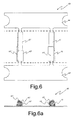
- figures 6 and 6a show a possible variant of this embodiment.
- the shape and size of the blocking means 63, 63', ... may be optimized in order not to block the slit of the filiform elements in the case the final device so requires.
- the two variants of the embodiments shown in figures 5 and 6 provide for the use of the portion of the supporting strip 64, 64' for the anchorage to the support in the final device.
- Such a use which may also occur when the embodiment provides for supporting a single filiform element, allows for the possible use of welding as a fixing process, because it does not lead to risks of undesired overheating of the filiform element.
- this may be used for fixing the support directly onto the surface of the shield present in some types of lamps.
- this support has the secondary effect of making particularly effective the activation process of the active material.
- Useful materials for building the support according to the present invention are, for example, nickel plated iron, cold laminated steel, stainless steel; in a preferred embodiment the material of the support is the same material of the filiform element.
- FIG. 7 A support 70 has been improved by a perforated lateral metal extension 72 able to improve the induced heating currents in correspondence of the filiform element 71 that is fixed to the support by two blocking means 73 and 73'.
- the lateral metal extension may only optionally act as anchoring mean to the device (for example by welding). In fact similar embodiments are applicable even if also mechanical anchoring elements are present.
- the active material comprises powders for mercury release
- these are preferably formed of the compounds described in patent US 3657589 , that is compounds Ti x Z y Hg z wherein x and y vary from 0 to 13, with the proviso that their sum is included between 3 and 13 and z is 1 or 2.
- the use of Ti 3 Hg is preferred.
- These compounds may be used also in combination with promoters that maximize the mercury release.
- Said promoters are formed of copper together with at least one second element selected among tin, indium and silver, as described in patent EP0669639 , or of copper and silicon, as described in patent EP0691670 , or of copper, tin, and rare earths, as described in patent EP0737995 .
- mercury-releasing compounds can be used, comprising a weight percentage of titanium ranging from 10% to 42%, of copper ranging from 14% to 50%, of mercury from 20% to 50% and a weight percentage between 1% and 20% of one or more elements selected among tin, chromium and silicon, as described in international application WO2006/008771 , or ternary titanium-copper-mercury compounds such as those described in patent GB2056490 .
- the active material may advantageously comprise, in addition to a mercury compound, also a getter material, for example a Zr-A1 alloy comprising 16% of aluminum, described in patent US3203901 , or a Zr-Co-MM alloy, wherein MM indicates Y, La, Ce, Pr, Nd, Rare Earths metals or mixtures of these elements, comprising about 80% by weight of Zirconium, 15% of Cobalt and the rest MM.
- a getter material for example a Zr-A1 alloy comprising 16% of aluminum, described in patent US3203901 , or a Zr-Co-MM alloy, wherein MM indicates Y, La, Ce, Pr, Nd, Rare Earths metals or mixtures of these elements, comprising about 80% by weight of Zirconium, 15% of Cobalt and the rest MM.
- a getter material for example a Zr-A1 alloy comprising 16% of aluminum, described in patent US3203901 , or a Zr-Co-MM alloy,
- the weight ratio between the powders of the mercury releasing compound and the powders of the getter material is comprised between 8:2 and 1:9.
- the active material when it is only a getter material, it may be of an evaporable type, such as e.g. Ba-Al or a combination of a Ba-Al alloy with Ni or a getter of a non-evaporable type, such as e.g. yttrium and its binary alloys, Zr-Al, Zr-Co-MM, Zr-Fe-Y alloys or, more generally, Zr-M-Y alloys.
- an evaporable type such as e.g. Ba-Al or a combination of a Ba-Al alloy with Ni
- a getter of a non-evaporable type such as e.g. yttrium and its binary alloys, Zr-Al, Zr-Co-MM, Zr-Fe-Y alloys or, more generally, Zr-M-Y alloys.
- this preferably involves the use of a starting material formed of a metal strip (preferably steel or nickel plated iron), that also may have a possible metallic or polymeric coating, having the purpose of improving the mechanical or aesthetical features or the features of resistance to corrosion phenomena.
- the strip is formed by means of two subsequent and automatized steps, respectively of stamping and bending.
- the possible final riveting step allows for fixing said support element of the filiform element containing the active material.
- the invention in a second aspect thereof, relates to a lamp containing a support for filiform elements containing an active material in form of powders, comprising blocking means of the filiform element on said support, anchoring means for said support, characterized in that said blocking means exert a compression on the filiform element that is comprised between 25 and 90 MPa.
- FIG 8 there is shown a cross-sectional view of a lamp that may contain the support according to the present invention.
- a sectional view is represented of a generic high-pressure discharge lamp 80, of the type wherein the electric connectors are only on one side of the lamp, that is formed of an external bulb 81, generally in glass or quartz, wherein the so-called burner 82 is provided, formed of a generally spherical or cylindrical container made of translucent alumina or quartz.
- two electrodes 83, 83' are provided, and inside it a filler gas and one or more metals or compounds in form of vapor or vaporizable by turning on of the lamp (not shown), that are the medium wherein the discharge takes place, are provided; when they are made of quartz, the two ends 84, 84' of the burner are closed by hot compression.
- the burner is maintained in its position by means of two metal supporting parts, 85, 86 which also have the function of electrically connecting the electrodes and of which one typically has a portion positioned parallely to the burner structure.
- support 86 there is positioned support 20 for filiform elements, made according to the present invention, positioned between element 86 and bulb 81, parallel to element 86, so as to cause the least possible dimming of the light emission of the lamp.
- the structure of the lamp is further completed by external contacts 88, 88', metal feedthroughs 87, 87' and one closure portion of bulb 89.
- the anchoring means are fixed by mechanical deformation or by elastically tying the support for filiform elements to one of the structural elements of the lamp, such as for example support threads of the burner (as shown in figure 8 ) or electrical feedthroughs in high-pressure discharge lamps or support wires of the tungsten filament, named lead-wires, or additional wires, known as third electrode, for supporting screening elements in FL.
- the active material comprises powders of mercury releasing compounds, and optionally getter material powders; in the case of high-intensity discharge lamps, the active material comprises getter material powders.
- the lamp comprises a support for filiform elements provided with lateral extensions, which support is fixed to one of the lead-wires of the lamp or to the so-called third electrode by means of the anchoring means.
- the lateral extensions having suitable length could be bent and shaped so as to have a shield in form of a closed or semi-closed ring around the electrode or, as previously mentioned, it could be placed above the electrode at a suitable distance.
- An active material containing system has been obtained by fixing with a compression action of about 42 MPa a filiform element (length about 5 mm, and a trapezoidal cross-section having a maximum transversal width about 1 mm and height about 0.8 mm) on a support according to the present invention as shown in figure 4 .
- a filiform element length about 5 mm, and a trapezoidal cross-section having a maximum transversal width about 1 mm and height about 0.8 mm
- the system Under vacuum conditions (pressure lower than 10 -4 mbar), the system has been heated for 20 and 30 seconds by an induction coil with a diameter of 40 mm, coil connected to an RF power source with a nominal power of 2 KW.
- the system during the test, has been perpendicularly coupled to the electro-magnetic field.
- Table 1 the deformation of the cross-section of the filiform element as effect of the compression action and the effective temperatures obtained by RF induction have been reported
- An active material containing system has been obtained by fixing a filiform dispensing element as in the Example 1 but using a compression action of about 18 MPa.
- Table 1 the deformation of the cross-section of the filiform element as effect of the compression action and the effective temperatures obtained by RF induction have been reported Table 1
- a support obtained according the present invention is not only able to guarantee an effective blocking of the filiform element, but also an improved heating thereof during the activation process: the sample according to the present invention described in the Example 1, in fact, is heated to temperature above 500°C (as requested by the most popular active materials) after 30 seconds, as required in the manufacturing production line of several devices.
- the comparative example even if the filiform element is blocked on the support, does not meet the required efficiency in the activation step because temperature have seen to be lower than the desired ones.
Claims (19)
- Support (10 ; 20 ; 30 ; 40 ; 50 ; 60 ; 70) pour au moins un élément filiforme (11 ; 41 ; 51 ; 61 ; 71) contenant un matériau actif sous la forme de poudres (12), comprenant des moyens de blocage (13, 13' ; 23, 23' ; ...) de chaque élément filiforme sur ledit support, des moyens d'ancrage (14 ; 44, 44', ...) pour ledit support, caractérisé en ce que ledit moyens de blocage exercent une compression comprise entre 25 et 90 MPa sur l'élément filiforme.
- Support selon la revendication 1, dans lequel ladite compression est comprise entre 25 et 55 MPa.
- Support selon la revendication 1, dans lequel la surface de la section transversale de l'élément filiforme qui est en correspondance avec les moyens de blocage est réduite, de moins de 8 %, par rapport à la surface de la section transversale de l'élément filiforme qui n'est pas en correspondance avec lesdits moyens de blocage.
- Support selon la revendication 3, dans lequel ladite réduction de la surface de la section transversale est comprise entre 1,5 % et 4 % de la surface de la section transversale de l'élément filiforme qui n'est pas en correspondance avec lesdits moyens de blocage.
- Support selon la revendication 1, dans lequel lesdits moyens d'ancrage sont maintenus par sertissage ou par la seule force élastique.
- Support selon la revendication 1, dans lequel lesdits moyens de blocage sont présents sur la partie terminale de l'élément filiforme et comportent une section terminale courbe.
- Support selon la revendication 6, dans lequel ladite section terminale courbe ne recouvre pas plus de 60 % de la surface aux extrémités de l'élément filiforme.
- Support selon la revendication 1, dans lequel des extensions latérales (31, 31') sont prévues.
- Support selon la revendication 1, dans lequel le matériau du support est du fer ou de l'acier plaqué au nickel.
- Support selon la revendication 1, dans lequel ledit élément filiforme est pourvu d'une fente (15 ; 45) sur une surface latérale.
- Support selon la revendication 1, dans lequel ledit élément filiforme contient des poudres d'un ou plusieurs matériaux getter.
- Support selon la revendication 1, dans lequel ledit élément filiforme contient des poudres d'un ou plusieurs composés à décharge de mercure.
- Support selon la revendication 12, dans lequel ledit élément filiforme contient également des poudres d'un ou plusieurs matériaux getter.
- Lampe comprenant un support pour éléments filiformes contenant des poudres d'un matériau actif selon la revendication 1.
- Lampe selon la revendication 14, dans laquelle ladite lampe est une lampe à mercure basse pression.
- Lampe selon la revendication 14, dans laquelle ledit matériau actif contient des poudres d'un ou plusieurs composés à décharge de mercure.
- Lampe selon la revendication 16, dans laquelle ledit matériau actif contient des poudres d'un ou plusieurs matériaux getter.
- Lampe selon la revendication 14, dans laquelle ladite lampe comprend un brûleur.
- Lampe selon la revendication 18, dans laquelle ledit matériau actif contient des poudres d'un ou plusieurs matériaux getter.
Applications Claiming Priority (3)
| Application Number | Priority Date | Filing Date | Title |
|---|---|---|---|
| IT001255A ITMI20091255A1 (it) | 2009-07-15 | 2009-07-15 | Supporto per elementi filiformi contenenti un materiale attivo |
| ITMI20100085 ITMI20100085U1 (it) | 2010-03-24 | 2010-03-24 | Supporto per elementi filiformi contenenti un materiale attivo |
| PCT/EP2010/059706 WO2011006811A1 (fr) | 2009-07-15 | 2010-07-07 | Support pour éléments filiformes contenant une substance active |
Publications (2)
| Publication Number | Publication Date |
|---|---|
| EP2319066A1 EP2319066A1 (fr) | 2011-05-11 |
| EP2319066B1 true EP2319066B1 (fr) | 2011-12-28 |
Family
ID=43448966
Family Applications (1)
| Application Number | Title | Priority Date | Filing Date |
|---|---|---|---|
| EP10732691A Not-in-force EP2319066B1 (fr) | 2009-07-15 | 2010-07-07 | Support pour éléments filiformes contenant une substance active |
Country Status (8)
| Country | Link |
|---|---|
| US (1) | US8427051B2 (fr) |
| EP (1) | EP2319066B1 (fr) |
| JP (1) | JP5560330B2 (fr) |
| KR (1) | KR20120052317A (fr) |
| CN (1) | CN102473566B (fr) |
| AT (1) | ATE539443T1 (fr) |
| TW (1) | TW201133545A (fr) |
| WO (1) | WO2011006811A1 (fr) |
Families Citing this family (5)
| Publication number | Priority date | Publication date | Assignee | Title |
|---|---|---|---|---|
| ITMI20120940A1 (it) * | 2012-05-31 | 2013-12-01 | Getters Spa | Composizioni perfezionate per il dosaggio di mercurio |
| ITMI20131171A1 (it) * | 2013-07-11 | 2015-01-11 | Getters Spa | Erogatore migliorato di vapori metallici |
| ITMI20131658A1 (it) * | 2013-10-08 | 2015-04-09 | Getters Spa | Combinazione di materiali per dispositivi di rilascio di mercurio e dispositivi contenenti detta combinazione di materiali |
| EP3262343B1 (fr) * | 2015-02-26 | 2018-09-05 | Philips Lighting Holding B.V. | Dispositif d'éclairage avec réservoir pour une substance réactive |
| CN107400854B (zh) * | 2017-07-17 | 2019-01-22 | 云南师范大学 | 非蒸散型低温激活锆基吸气剂薄膜及其制备方法 |
Family Cites Families (28)
| Publication number | Priority date | Publication date | Assignee | Title |
|---|---|---|---|---|
| US1733809A (en) | 1928-06-26 | 1929-10-29 | Westinghouse Lamp Co | Means for gettering electrical discharge devices |
| US2928925A (en) | 1956-08-15 | 1960-03-15 | Rca Corp | Getter structure |
| US3203901A (en) | 1962-02-15 | 1965-08-31 | Porta Paolo Della | Method of manufacturing zirconiumaluminum alloy getters |
| GB1248184A (en) | 1969-04-03 | 1971-09-29 | Westinghouse Electric Corp | Yttrium alloy getter |
| US3657589A (en) | 1969-10-20 | 1972-04-18 | Getters Spa | Mercury generation |
| GB1575890A (en) * | 1978-03-31 | 1980-10-01 | Thorn Electrical Ind Ltd | Heating of dosing capsule |
| IT1115156B (it) | 1979-04-06 | 1986-02-03 | Getters Spa | Leghe zr-fe per l'assorbimento di idrogeno a basse temperature |
| IT1193796B (it) | 1979-07-19 | 1988-08-24 | Getters Spa | Composizione e dispositivo per l'emissione di mercurio e tubi elettronici comprendenti tale dispositivo |
| JPH03285232A (ja) | 1990-03-30 | 1991-12-16 | Sanyo Electric Co Ltd | ワイヤーゲッター支持構造 |
| JP3285232B2 (ja) | 1992-09-25 | 2002-05-27 | 松下電工株式会社 | 表示灯付スイッチ |
| JPH06111775A (ja) * | 1992-09-30 | 1994-04-22 | Toshiba Lighting & Technol Corp | 低圧放電灯 |
| IT1273338B (it) | 1994-02-24 | 1997-07-08 | Getters Spa | Combinazione di materiali per dispositivi erogatori di mercurio metodo di preparazione e dispositivi cosi' ottenuti |
| IT1270598B (it) | 1994-07-07 | 1997-05-07 | Getters Spa | Combinazione di materiali per dispositivi erogatori di mercurio metodo di preparazione e dispositivi cosi' ottenuti |
| IT1273531B (it) | 1995-04-10 | 1997-07-08 | Getters Spa | Combinazioni di materiali per dispositivi integrati getter ed erogatori di mercurio e dispositivi cosi' ottenuti |
| IT1290451B1 (it) | 1997-04-03 | 1998-12-03 | Getters Spa | Leghe getter non evaporabili |
| IT1291974B1 (it) | 1997-05-22 | 1999-01-25 | Getters Spa | Dispositivo e metodo per l'introduzione di piccole quantita' di mercurio in lampade fluorescenti |
| US6452322B1 (en) * | 1998-11-27 | 2002-09-17 | Sony Corporation | Cathode-ray tube and its getter supporter |
| JP2000317247A (ja) * | 1999-05-14 | 2000-11-21 | Sumitomo Metal Ind Ltd | ガス吸収ゲッターおよびその製造方法 |
| US6456004B1 (en) * | 1999-09-10 | 2002-09-24 | General Electric Company | Fluorescent lamp having uniquely configured container containing amalgam for regulating mercury vapor equilibrium |
| IT1317117B1 (it) | 2000-03-06 | 2003-05-27 | Getters Spa | Metodo per la preparazione di dispositivi dispensatori di mercurio dausare in lampade fluorescenti |
| ITMI20012033A1 (it) | 2001-09-28 | 2003-03-28 | Getters Spa | Leghe getter per l'assorbimento di idrogeno a tempersture elevate |
| ITMI20041494A1 (it) | 2004-07-23 | 2004-10-23 | Getters Spa | Composizioni per il rilascio di mercurio e processo per la loro produzione |
| ITMI20050281A1 (it) | 2005-02-23 | 2006-08-24 | Getters Spa | Lampada a scarica ad alta pressione miniaturizzata contenente un dispositivo getter |
| ITMI20060361A1 (it) | 2006-02-28 | 2007-09-01 | Getters Spa | Assorbimento di idrogeno mediante l'impiego di leghe getter non evaporabili metodo ed applicazioni |
| GB0605960D0 (en) | 2006-03-24 | 2006-05-03 | Galley Geoffrey H | Expandable spinal prosthesis |
| CN201048119Y (zh) * | 2007-06-15 | 2008-04-16 | 南京泰欧科技开发有限公司 | 小型释汞吸气元件 |
| DE102007033879A1 (de) * | 2007-07-20 | 2009-01-22 | Osram Gesellschaft mit beschränkter Haftung | Trägerelement, an welchem ein Hg-haltiges Material zur Anbringung in eine Entladungslampe ausgebildet ist, und Entladungslampe mit einem derartigen Trägerelement |
| ITRM20080334A1 (it) | 2008-06-25 | 2009-12-26 | Getters Spa | Lampada fluorescente a catodo caldo contenente un dispositivo per il rilascio di mercurio e getter |
-
2010
- 2010-07-07 JP JP2012519977A patent/JP5560330B2/ja not_active Expired - Fee Related
- 2010-07-07 AT AT10732691T patent/ATE539443T1/de active
- 2010-07-07 KR KR1020127003874A patent/KR20120052317A/ko not_active Application Discontinuation
- 2010-07-07 CN CN201080029342.6A patent/CN102473566B/zh not_active Expired - Fee Related
- 2010-07-07 US US12/936,388 patent/US8427051B2/en active Active
- 2010-07-07 WO PCT/EP2010/059706 patent/WO2011006811A1/fr active Application Filing
- 2010-07-07 EP EP10732691A patent/EP2319066B1/fr not_active Not-in-force
- 2010-07-09 TW TW099122665A patent/TW201133545A/zh unknown
Also Published As
| Publication number | Publication date |
|---|---|
| EP2319066A1 (fr) | 2011-05-11 |
| JP2012533160A (ja) | 2012-12-20 |
| US20110204774A1 (en) | 2011-08-25 |
| CN102473566B (zh) | 2015-08-05 |
| KR20120052317A (ko) | 2012-05-23 |
| CN102473566A (zh) | 2012-05-23 |
| ATE539443T1 (de) | 2012-01-15 |
| TW201133545A (en) | 2011-10-01 |
| US8427051B2 (en) | 2013-04-23 |
| JP5560330B2 (ja) | 2014-07-23 |
| WO2011006811A1 (fr) | 2011-01-20 |
Similar Documents
| Publication | Publication Date | Title |
|---|---|---|
| EP2319066B1 (fr) | Support pour éléments filiformes contenant une substance active | |
| US3549937A (en) | Low pressure mercury vapour discharge lamp including an alloy type getter coating | |
| EP2419919B1 (fr) | Lampe à décharge améliorée | |
| US7135811B2 (en) | Shroud holder for quartz and ceramic arc tubes | |
| EP1704576B1 (fr) | Procede de fabrication d'une lampe a decharge haute pression compacte | |
| WO2009156334A1 (fr) | Lampe fluorescente à cathode chaude contenant un dispositif de libération de mercure et un dégazeur | |
| KR970005770B1 (ko) | 저압 수은 증기 방전등 | |
| US8076848B2 (en) | Mercury dispensing system for fluorescent lamps | |
| EP1004138B1 (fr) | Lampe a vapeur de mercure a basse pression | |
| US3549936A (en) | Low pressure mercury vapor discharge lamps including an alloy type getter coating | |
| JP3956040B2 (ja) | 蛍光ランプおよび照明装置 | |
| TW201241869A (en) | Ceramic discharge metal halide (CDM) lamp and method of manufacture thereof | |
| JP2001250503A (ja) | 蛍光ランプ | |
| EP2395540A1 (fr) | Positionnement d'amalgame auxiliaire dans une lampe fluorescente compact | |
| JP2006269283A (ja) | 蛍光ランプおよび照明器具 | |
| JP2005346976A (ja) | 蛍光ランプおよび照明器具 | |
| JPH10302717A (ja) | 低圧水銀蒸気放電ランプおよび照明装置 | |
| US20060097617A1 (en) | Cathode unit for fluorescent lamps | |
| JPH05275063A (ja) | 低圧水銀蒸気放電灯 | |
| JP2001291488A (ja) | 二重環形蛍光ランプ | |
| JPH10223177A (ja) | 低圧水銀蒸気放電ランプ | |
| JP2005235659A (ja) | 蛍光ランプおよび照明器具 | |
| JPH01260753A (ja) | 低圧水銀蒸気放電灯 |
Legal Events
| Date | Code | Title | Description |
|---|---|---|---|
| PUAI | Public reference made under article 153(3) epc to a published international application that has entered the european phase |
Free format text: ORIGINAL CODE: 0009012 |
|
| 17P | Request for examination filed |
Effective date: 20110303 |
|
| AK | Designated contracting states |
Kind code of ref document: A1 Designated state(s): AL AT BE BG CH CY CZ DE DK EE ES FI FR GB GR HR HU IE IS IT LI LT LU LV MC MK MT NL NO PL PT RO SE SI SK SM TR |
|
| AX | Request for extension of the european patent |
Extension state: BA ME RS |
|
| GRAP | Despatch of communication of intention to grant a patent |
Free format text: ORIGINAL CODE: EPIDOSNIGR1 |
|
| GRAS | Grant fee paid |
Free format text: ORIGINAL CODE: EPIDOSNIGR3 |
|
| GRAA | (expected) grant |
Free format text: ORIGINAL CODE: 0009210 |
|
| DAX | Request for extension of the european patent (deleted) | ||
| AK | Designated contracting states |
Kind code of ref document: B1 Designated state(s): AL AT BE BG CH CY CZ DE DK EE ES FI FR GB GR HR HU IE IS IT LI LT LU LV MC MK MT NL NO PL PT RO SE SI SK SM TR |
|
| REG | Reference to a national code |
Ref country code: GB Ref legal event code: FG4D |
|
| REG | Reference to a national code |
Ref country code: CH Ref legal event code: EP |
|
| REG | Reference to a national code |
Ref country code: AT Ref legal event code: REF Ref document number: 539443 Country of ref document: AT Kind code of ref document: T Effective date: 20120115 |
|
| REG | Reference to a national code |
Ref country code: IE Ref legal event code: FG4D |
|
| REG | Reference to a national code |
Ref country code: DE Ref legal event code: R096 Ref document number: 602010000573 Country of ref document: DE Effective date: 20120315 |
|
| REG | Reference to a national code |
Ref country code: NL Ref legal event code: VDEP Effective date: 20111228 |
|
| PG25 | Lapsed in a contracting state [announced via postgrant information from national office to epo] |
Ref country code: LT Free format text: LAPSE BECAUSE OF FAILURE TO SUBMIT A TRANSLATION OF THE DESCRIPTION OR TO PAY THE FEE WITHIN THE PRESCRIBED TIME-LIMIT Effective date: 20111228 Ref country code: NO Free format text: LAPSE BECAUSE OF FAILURE TO SUBMIT A TRANSLATION OF THE DESCRIPTION OR TO PAY THE FEE WITHIN THE PRESCRIBED TIME-LIMIT Effective date: 20120328 |
|
| RIN2 | Information on inventor provided after grant (corrected) |
Inventor name: GIORGI, STEFANO, PAOLO Inventor name: CORAZZA, ALESSIO Inventor name: RIVA, MAURO Inventor name: JUHR, WERNER |
|
| LTIE | Lt: invalidation of european patent or patent extension |
Effective date: 20111228 |
|
| PG25 | Lapsed in a contracting state [announced via postgrant information from national office to epo] |
Ref country code: HR Free format text: LAPSE BECAUSE OF FAILURE TO SUBMIT A TRANSLATION OF THE DESCRIPTION OR TO PAY THE FEE WITHIN THE PRESCRIBED TIME-LIMIT Effective date: 20111228 Ref country code: LV Free format text: LAPSE BECAUSE OF FAILURE TO SUBMIT A TRANSLATION OF THE DESCRIPTION OR TO PAY THE FEE WITHIN THE PRESCRIBED TIME-LIMIT Effective date: 20111228 Ref country code: GR Free format text: LAPSE BECAUSE OF FAILURE TO SUBMIT A TRANSLATION OF THE DESCRIPTION OR TO PAY THE FEE WITHIN THE PRESCRIBED TIME-LIMIT Effective date: 20120329 Ref country code: SI Free format text: LAPSE BECAUSE OF FAILURE TO SUBMIT A TRANSLATION OF THE DESCRIPTION OR TO PAY THE FEE WITHIN THE PRESCRIBED TIME-LIMIT Effective date: 20111228 Ref country code: SE Free format text: LAPSE BECAUSE OF FAILURE TO SUBMIT A TRANSLATION OF THE DESCRIPTION OR TO PAY THE FEE WITHIN THE PRESCRIBED TIME-LIMIT Effective date: 20111228 |
|
| PG25 | Lapsed in a contracting state [announced via postgrant information from national office to epo] |
Ref country code: CY Free format text: LAPSE BECAUSE OF FAILURE TO SUBMIT A TRANSLATION OF THE DESCRIPTION OR TO PAY THE FEE WITHIN THE PRESCRIBED TIME-LIMIT Effective date: 20111228 |
|
| PG25 | Lapsed in a contracting state [announced via postgrant information from national office to epo] |
Ref country code: SK Free format text: LAPSE BECAUSE OF FAILURE TO SUBMIT A TRANSLATION OF THE DESCRIPTION OR TO PAY THE FEE WITHIN THE PRESCRIBED TIME-LIMIT Effective date: 20111228 Ref country code: IS Free format text: LAPSE BECAUSE OF FAILURE TO SUBMIT A TRANSLATION OF THE DESCRIPTION OR TO PAY THE FEE WITHIN THE PRESCRIBED TIME-LIMIT Effective date: 20120428 Ref country code: EE Free format text: LAPSE BECAUSE OF FAILURE TO SUBMIT A TRANSLATION OF THE DESCRIPTION OR TO PAY THE FEE WITHIN THE PRESCRIBED TIME-LIMIT Effective date: 20111228 Ref country code: NL Free format text: LAPSE BECAUSE OF FAILURE TO SUBMIT A TRANSLATION OF THE DESCRIPTION OR TO PAY THE FEE WITHIN THE PRESCRIBED TIME-LIMIT Effective date: 20111228 Ref country code: BG Free format text: LAPSE BECAUSE OF FAILURE TO SUBMIT A TRANSLATION OF THE DESCRIPTION OR TO PAY THE FEE WITHIN THE PRESCRIBED TIME-LIMIT Effective date: 20120328 |
|
| PG25 | Lapsed in a contracting state [announced via postgrant information from national office to epo] |
Ref country code: PT Free format text: LAPSE BECAUSE OF FAILURE TO SUBMIT A TRANSLATION OF THE DESCRIPTION OR TO PAY THE FEE WITHIN THE PRESCRIBED TIME-LIMIT Effective date: 20120430 Ref country code: RO Free format text: LAPSE BECAUSE OF FAILURE TO SUBMIT A TRANSLATION OF THE DESCRIPTION OR TO PAY THE FEE WITHIN THE PRESCRIBED TIME-LIMIT Effective date: 20111228 Ref country code: PL Free format text: LAPSE BECAUSE OF FAILURE TO SUBMIT A TRANSLATION OF THE DESCRIPTION OR TO PAY THE FEE WITHIN THE PRESCRIBED TIME-LIMIT Effective date: 20111228 |
|
| REG | Reference to a national code |
Ref country code: AT Ref legal event code: MK05 Ref document number: 539443 Country of ref document: AT Kind code of ref document: T Effective date: 20111228 |
|
| PG25 | Lapsed in a contracting state [announced via postgrant information from national office to epo] |
Ref country code: DK Free format text: LAPSE BECAUSE OF FAILURE TO SUBMIT A TRANSLATION OF THE DESCRIPTION OR TO PAY THE FEE WITHIN THE PRESCRIBED TIME-LIMIT Effective date: 20111228 |
|
| PLBE | No opposition filed within time limit |
Free format text: ORIGINAL CODE: 0009261 |
|
| STAA | Information on the status of an ep patent application or granted ep patent |
Free format text: STATUS: NO OPPOSITION FILED WITHIN TIME LIMIT |
|
| 26N | No opposition filed |
Effective date: 20121001 |
|
| REG | Reference to a national code |
Ref country code: DE Ref legal event code: R097 Ref document number: 602010000573 Country of ref document: DE Effective date: 20121001 |
|
| PG25 | Lapsed in a contracting state [announced via postgrant information from national office to epo] |
Ref country code: AT Free format text: LAPSE BECAUSE OF FAILURE TO SUBMIT A TRANSLATION OF THE DESCRIPTION OR TO PAY THE FEE WITHIN THE PRESCRIBED TIME-LIMIT Effective date: 20111228 |
|
| PG25 | Lapsed in a contracting state [announced via postgrant information from national office to epo] |
Ref country code: MC Free format text: LAPSE BECAUSE OF NON-PAYMENT OF DUE FEES Effective date: 20120731 Ref country code: MK Free format text: LAPSE BECAUSE OF FAILURE TO SUBMIT A TRANSLATION OF THE DESCRIPTION OR TO PAY THE FEE WITHIN THE PRESCRIBED TIME-LIMIT Effective date: 20111228 |
|
| REG | Reference to a national code |
Ref country code: FR Ref legal event code: ST Effective date: 20130329 |
|
| PG25 | Lapsed in a contracting state [announced via postgrant information from national office to epo] |
Ref country code: FR Free format text: LAPSE BECAUSE OF NON-PAYMENT OF DUE FEES Effective date: 20120731 Ref country code: ES Free format text: LAPSE BECAUSE OF FAILURE TO SUBMIT A TRANSLATION OF THE DESCRIPTION OR TO PAY THE FEE WITHIN THE PRESCRIBED TIME-LIMIT Effective date: 20120408 |
|
| REG | Reference to a national code |
Ref country code: IE Ref legal event code: MM4A |
|
| PG25 | Lapsed in a contracting state [announced via postgrant information from national office to epo] |
Ref country code: FI Free format text: LAPSE BECAUSE OF FAILURE TO SUBMIT A TRANSLATION OF THE DESCRIPTION OR TO PAY THE FEE WITHIN THE PRESCRIBED TIME-LIMIT Effective date: 20111228 |
|
| PG25 | Lapsed in a contracting state [announced via postgrant information from national office to epo] |
Ref country code: IE Free format text: LAPSE BECAUSE OF NON-PAYMENT OF DUE FEES Effective date: 20120707 Ref country code: MT Free format text: LAPSE BECAUSE OF FAILURE TO SUBMIT A TRANSLATION OF THE DESCRIPTION OR TO PAY THE FEE WITHIN THE PRESCRIBED TIME-LIMIT Effective date: 20111228 |
|
| PG25 | Lapsed in a contracting state [announced via postgrant information from national office to epo] |
Ref country code: AL Free format text: LAPSE BECAUSE OF FAILURE TO SUBMIT A TRANSLATION OF THE DESCRIPTION OR TO PAY THE FEE WITHIN THE PRESCRIBED TIME-LIMIT Effective date: 20111228 |
|
| PG25 | Lapsed in a contracting state [announced via postgrant information from national office to epo] |
Ref country code: TR Free format text: LAPSE BECAUSE OF FAILURE TO SUBMIT A TRANSLATION OF THE DESCRIPTION OR TO PAY THE FEE WITHIN THE PRESCRIBED TIME-LIMIT Effective date: 20111228 |
|
| PG25 | Lapsed in a contracting state [announced via postgrant information from national office to epo] |
Ref country code: LU Free format text: LAPSE BECAUSE OF NON-PAYMENT OF DUE FEES Effective date: 20120707 Ref country code: SM Free format text: LAPSE BECAUSE OF FAILURE TO SUBMIT A TRANSLATION OF THE DESCRIPTION OR TO PAY THE FEE WITHIN THE PRESCRIBED TIME-LIMIT Effective date: 20111228 |
|
| PG25 | Lapsed in a contracting state [announced via postgrant information from national office to epo] |
Ref country code: HU Free format text: LAPSE BECAUSE OF FAILURE TO SUBMIT A TRANSLATION OF THE DESCRIPTION OR TO PAY THE FEE WITHIN THE PRESCRIBED TIME-LIMIT Effective date: 20100707 |
|
| REG | Reference to a national code |
Ref country code: CH Ref legal event code: PL |
|
| PG25 | Lapsed in a contracting state [announced via postgrant information from national office to epo] |
Ref country code: CH Free format text: LAPSE BECAUSE OF NON-PAYMENT OF DUE FEES Effective date: 20140731 Ref country code: LI Free format text: LAPSE BECAUSE OF NON-PAYMENT OF DUE FEES Effective date: 20140731 |
|
| PGFP | Annual fee paid to national office [announced via postgrant information from national office to epo] |
Ref country code: DE Payment date: 20200729 Year of fee payment: 11 Ref country code: GB Payment date: 20200727 Year of fee payment: 11 |
|
| PGFP | Annual fee paid to national office [announced via postgrant information from national office to epo] |
Ref country code: BE Payment date: 20200727 Year of fee payment: 11 Ref country code: IT Payment date: 20200724 Year of fee payment: 11 |
|
| PGFP | Annual fee paid to national office [announced via postgrant information from national office to epo] |
Ref country code: CZ Payment date: 20210623 Year of fee payment: 12 |
|
| REG | Reference to a national code |
Ref country code: DE Ref legal event code: R119 Ref document number: 602010000573 Country of ref document: DE |
|
| GBPC | Gb: european patent ceased through non-payment of renewal fee |
Effective date: 20210707 |
|
| REG | Reference to a national code |
Ref country code: BE Ref legal event code: MM Effective date: 20210731 |
|
| PG25 | Lapsed in a contracting state [announced via postgrant information from national office to epo] |
Ref country code: GB Free format text: LAPSE BECAUSE OF NON-PAYMENT OF DUE FEES Effective date: 20210707 Ref country code: DE Free format text: LAPSE BECAUSE OF NON-PAYMENT OF DUE FEES Effective date: 20220201 |
|
| PG25 | Lapsed in a contracting state [announced via postgrant information from national office to epo] |
Ref country code: IT Free format text: LAPSE BECAUSE OF NON-PAYMENT OF DUE FEES Effective date: 20210707 Ref country code: BE Free format text: LAPSE BECAUSE OF NON-PAYMENT OF DUE FEES Effective date: 20210731 |
|
| PG25 | Lapsed in a contracting state [announced via postgrant information from national office to epo] |
Ref country code: CZ Free format text: LAPSE BECAUSE OF NON-PAYMENT OF DUE FEES Effective date: 20220707 |