EP2317263A2 - Auszugschale und damit ausgestattetes Kältegerät - Google Patents
Auszugschale und damit ausgestattetes Kältegerät Download PDFInfo
- Publication number
- EP2317263A2 EP2317263A2 EP10187843A EP10187843A EP2317263A2 EP 2317263 A2 EP2317263 A2 EP 2317263A2 EP 10187843 A EP10187843 A EP 10187843A EP 10187843 A EP10187843 A EP 10187843A EP 2317263 A2 EP2317263 A2 EP 2317263A2
- Authority
- EP
- European Patent Office
- Prior art keywords
- pull
- out tray
- strip
- web
- tray according
- Prior art date
- Legal status (The legal status is an assumption and is not a legal conclusion. Google has not performed a legal analysis and makes no representation as to the accuracy of the status listed.)
- Granted
Links
Images

Classifications
-
- F—MECHANICAL ENGINEERING; LIGHTING; HEATING; WEAPONS; BLASTING
- F25—REFRIGERATION OR COOLING; COMBINED HEATING AND REFRIGERATION SYSTEMS; HEAT PUMP SYSTEMS; MANUFACTURE OR STORAGE OF ICE; LIQUEFACTION SOLIDIFICATION OF GASES
- F25D—REFRIGERATORS; COLD ROOMS; ICE-BOXES; COOLING OR FREEZING APPARATUS NOT OTHERWISE PROVIDED FOR
- F25D25/00—Charging, supporting, and discharging the articles to be cooled
- F25D25/02—Charging, supporting, and discharging the articles to be cooled by shelves
- F25D25/024—Slidable shelves
- F25D25/025—Drawers
Definitions
- the present invention relates to a pull-out tray and a refrigerator equipped therewith.
- Conventional pull-out trays for refrigeration appliances are usually injection-molded in one or more parts from plastic and have on their front side an undercut depression into which a user can engage in order to pull the tray out of a refrigerator body.
- the undercut is located in an upper region of the recess, so that a user who wants to pull out the shell, must insert his fingers obliquely from below into the recess to pack a wall of the shell delimiting the undercut.
- Such a recess is well suited to exert a large pulling force on a pull-out shell, which is arranged approximately at waist level of a user or below. Since the fingers must engage in the recess from below, the user is forced to stoop far to handle a low-lying pull-out tray. Even with pullout trays, which are relatively high, arranged approximately at eye level of the user, such a recess is not fully satisfactory, since it forces an unnatural hand position in which no large tensile forces can be exercised.
- the object of the invention is to provide a pull-out tray for a refrigerator, which is easy and comfortable to handle, regardless of their installation height in the refrigerator.
- a refrigeration device is understood in particular to be a household refrigeration appliance, that is to say a refrigeration appliance that is used for housekeeping in households or in the gastronomy sector, and in particular for storing foods and / or drinks at specific temperatures, such as, for example, a refrigerator, a freezer, a refrigerated freezer combination or a refrigerator wine fridge.
- An extract tray is understood in particular to mean a container which is used for the storage of foods, such as, for example, a fruit and / or vegetable dish or a container for the storage of frozen goods.
- a second gripping zone is formed on an inner side of the front panel at a pull-out shell for a refrigerator with a front panel on the outside of a first grip zone is formed in a recess undercut in its upper region.
- the second grip zone can be reached from above by reaching into the pull-out shell. Therefore, in a low-lying pull-out tray, the user has to stoop less to reach the second handle zone than to reach the first. In particular, a low-loaded pull-out tray is easy to handle in this way.
- the user can reach the second grip zone by embracing the top edge of the front panel. With such a hand position, the user can generally exert more pulling force than if he attacks with his body facing palms on the first grip zones.
- the pull-out tray comprises a body forming a lower portion of the faceplate and a bar forming an upper portion of the faceplate.
- the two gripping zones preferably extend over the entire length of the bar. In particular, this makes it possible to manufacture the bar inexpensively as an extrusion profile.
- the strip may comprise a vertical web and a leg projecting from the web into the interior of the shell, wherein the grip zones are formed on a back side of the web above and below the leg, respectively.
- the protruding leg significantly increases the stiffness of the bar with low material costs.
- the web may form an inner surface of the undercut recess; Preferably, it does so only for an upper part of the recess, and a lower portion of the recess is formed by the main body.
- an edge of the leg facing away from the web and a front wall of the main body are expediently non-positively connected, for example by gluing, but preferably also in a form-fitting manner.
- the Figures 1 and 2 show in different perspectives a same pullout tray 1 for a refrigerator.
- the pull-out tray 1 has essentially the shape of a cuboid open at the top with a bottom plate 2, a front plate 3, flanks 4 and a rear wall 5.
- the bottom plate 2, the flanks 4, the rear wall 5 and a lower portion 6 of the front panel 3 are integrally connected in a molded plastic injection molded body. From the flanks 4 outwardly projecting horizontal ribs 10 are provided to be slidably supported on a carrier contour on the side walls of a refrigerator body and the movement of the pull-out shell 1 between a inserted and lead to an extended position, or to invisibly mount underneath a movement of the extension tray 1 leading telescopic rail.
- An upper portion of the front panel 3 is formed by an extruded strip 7, preferably made of aluminum. So that she feels so that she does not feel overly cold for a user, the bar 7 may be made of a plastic, which has a higher load capacity than that of the body. For aesthetic reasons, and also to make the bar 7 conspicuous to the user and thus cause him to grab the pull-out box on the bar 7, the plastic of such bar 7 is preferably metallized superficially. The ends of the strip 7 are also connected to preferably metallic corner pieces 8, which each form front upper corners of the pull-out shell 1.
- angular sheet metal profiles 9 which extend on the outer sides of the flanks 4 and the undersides of the ribs 10, and to which, depending on the embodiment, for example, the pull-out tray 1 leading telescopic rails can be attached or merely as a protective layer to Prevent fretting on the underside of the ribs 10 serve.
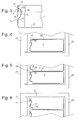
- Fig. 3 shows a cross section through the front part of in Fig. 1 and 2 shown extract tray.
- the strip 7 here has a cross-section similar to the letter h, with an outer edge of the strip 7 forming vertical web 11 and extending approximately from a center line of the web 11 in the ground downwardly extending leg 12.
- a free end of the leg 12 is flush into the area 6 of the body; both together form an undercut recess 13 extending essentially over the entire width of the pull-out tray 1.
- a first handle zone 14, on which a user can place his fingers in preference to the pull-out tray 1, is located on an inner side of the web 11 below the leg 12th
- a second grip zone 15 is provided on the inside of the bar 7 above the leg 12; To reach them, a user engages from above into the pull-out tray 1.
- the strip 7 is fixedly connected to the lower portion 6 of the front plate 3 preferably over the entire length of its edge facing away from the web 11 edge 19, either by gluing, by vertical overlap or a tongue and groove engagement, so that a possible deflection of the bar 7 transmits under a force exerted by the user pulling or pushing force on the area 6 and this contributes to the rigidity of the bar 7.
- Fig. 4 shows a schematic cross section of such a household refrigerator with a body 20 and a door 21, in which the accessibility of the grip zone 15 is ensured by a plate-shaped refrigerated goods 16, which is mounted on the pull-out tray 1, has a slightly smaller depth than this, so that between a front edge of the refrigerated goods carrier 16 and the web 11 always an engagement gap 17 remains free.
- the accessibility of the gripping zone 15 can be ensured by a step 18 each recessed at one edge between the front and bottom plate 3 and 2, thereby limiting the engagement in the next lower drawer limiting leading edge 23 behind the front panel 3.
- the step 18 recessed at the lower edge of the front plate 3 can be dispensed with, such as dashed outline in Fig. 6 indicated.
Landscapes
- Engineering & Computer Science (AREA)
- Chemical & Material Sciences (AREA)
- Combustion & Propulsion (AREA)
- Physics & Mathematics (AREA)
- Mechanical Engineering (AREA)
- Thermal Sciences (AREA)
- General Engineering & Computer Science (AREA)
- Packages (AREA)
- Details Of Rigid Or Semi-Rigid Containers (AREA)
- Refrigerator Housings (AREA)
- Cold Air Circulating Systems And Constructional Details In Refrigerators (AREA)
- Drawers Of Furniture (AREA)
Abstract
Description
- Die vorliegende Erfindung betrifft eine Auszugschale und ein damit ausgestattetes Kältegerät.
- Herkömmliche Auszugschalen für Kältegeräte sind meist ein- oder mehrteilig aus Kunststoff spritzgeformt und haben an ihrer Frontseite eine hinterschnittene Vertiefung, in die ein Benutzer eingreifen kann, um die Schale aus einem Kältegerätekorpus herauszuziehen. Meist befindet sich die Hinterschneidung in einem oberen Bereich der Aussparung, so dass ein Benutzer, der die Schale herausziehen will, seine Finger schräg von unten in die Aussparung einführen muss, um eine die Hinterschneidung begrenzende Wand der Schale zu packen. Eine solche Aussparung ist gut geeignet, um eine große Zugkraft auf eine Auszugschale auszuüben, die etwa in Hüfthöhe eines Benutzers oder darunter angeordnet ist. Da die Finger von unten in die Aussparung eingreifen müssen, ist der Benutzer gezwungen, sich weit zu bücken, um eine tief liegende Auszugschale zu handhaben. Auch bei Auszugschalen, die relativ hoch, etwa in Augenhöhe des Benutzers angeordnet sind, ist eine solche Aussparung nicht vollauf befriedigend, da sie zu einer unnatürlichen Handhaltung zwingt, in der keine großen Zugkräfte ausgeübt werden können.
- Aufgabe der Erfindung ist, eine Auszugschale für ein Kältegerät zu schaffen, die unabhängig von ihrer Einbauhöhe in dem Kältegerät leicht und bequem zu handhaben ist.
- Unter einem Kältegerät wird insbesondere ein Haushaltskältegerät verstanden, also ein Kältegerät das zur Haushaltsführung in Haushalten oder im Gastronomiebereich eingesetzt wird, und insbesondere dazu dient Lebensmittel und/oder Getränke bei bestimmten Temperaturen zu lagern, wie beispielsweise ein Kühlschrank, ein Gefrierschrank, eine Kühlgefrierkombination oder ein Weinkühlschrank.
- Unter einer Auszugsschale wird insbesondere ein Behälter verstanden, der zur Lagerung von Lebensmitteln verwendet wird, wie beispielsweise eine Obst- und/oder Gemüseschale oder ein Behälter zur Lagerung von Gefriergut.
- Die Aufgabe wird gelöst, indem bei einer Auszugschale für ein Kältegerät mit einer Frontplatte, an deren Außenseite eine erste Griffzone in einer in ihrem oberen Bereich hinterschnittenen Aussparung gebildet ist, eine zweite Griffzone an einer Innenseite der Frontplatte gebildet ist. Die zweite Griffzone ist durch Hineingreifen in die Auszugschale von oben erreichbar. Daher muss sich bei einer niedrig angeordnete Auszugschale der Benutzer zum Erreichen der zweiten Griffzone weniger weit bücken als zum Erreichen der ersten. Insbesondere eine gering beladene Auszugschale ist in dieser Weise bequem zu handhaben. Bei einer hoch angeordneten Schublade kann der Benutzer die zweite Griffzone erreichen, indem er die Oberkante der Frontplatte umgreift. Mit einer solchen Handhaltung kann der Benutzer im Allgemeinen mehr Zugkraft ausüben, als wenn er mit seinem Körper zugewandten Handflächen an den ersten Griffzonen angreift.
- Vorzugsweise umfasst die Auszugschale einen Grundkörper, der einen unteren Bereich der Frontplatte bildet, und eine Leiste, die einen oberen Bereich der Frontplatte bildet. Indem die Griffzonen an der Leiste angeordnet sind, können die Anforderungen an die Zugbelastbarkeit des Grundkörpers reduziert werden, und die Fertigungskosten der Auszugschale können reduziert werden.
- Die zwei Griffzonen erstrecken sich vorzugsweise über die gesamte Länge der Leiste. Insbesondere dadurch ist es möglich, die Leiste preiswert als Extrusionsprofil zu fertigen.
- Die Leiste kann einen vertikalen Steg und einen von dem Steg ins Innere der Schale abstehenden Schenkel umfassen, wobei die Griffzonen an einer Rückseite des Stegs jeweils oberhalb und unterhalb des Schenkels ausgebildet sind. Der abstehende Schenkel erhöht bei geringem Materialaufwand erheblich die Steifigkeit der Leiste.
- Der Steg kann eine Innenfläche der hinterschnittenen Aussparung bilden; vorzugsweise tut er das nur für einen oberen Teil der Aussparung, und ein unterer Bereich der Aussparung ist durch den Grundkörper gebildet.
- Um die Stabilität der Auszugschale zu verbessern, sind zweckmäßigerweise ein von dem Steg abgewandter Rand des Schenkels und eine vordere Wand des Grundkörpers kraftschlüssig, zum Beispiel durch Klebung, vorzugsweise aber auch formschlüssig verbunden.
- Wenn die oben beschriebene Auszugschale in einem Kältegerät zwischen einer eingeschobenen und einer herausgezogenen Stellung bewegbar gelagert ist, liegt die Vorderkante einer Abdeckung, die die Auszugschale in der eingeschobenen Stellung großenteils überdeckt, vorzugsweise hinter der zweiten Griffzone, um deren Erreichbarkeit zu gewährleisten.
- Weitere Merkmale und Vorteile der Erfindung ergeben sich aus der nachfolgenden Beschreibung von Ausführungsbeispielen unter Bezugnahme auf die beigefügten Figuren. Es zeigen:
- Fig. 1
- eine perspektivische Ansicht einer erfindungsgemäßen Auszugschale;
- Fig. 2
- eine weitere perspektivische Ansicht der Auszugschale gemäß
Fig. 1 ; - Fig. 3
- einen Schnitt durch eine Frontplatte der Auszugschale;
- Fig. 4
- einen schematischen Teilschnitt durch ein Kältegerät gemäß einer ersten Ausgestaltung;
- Fig. 5
- einen schematischen Teilschnitt durch ein Kältegerät gemäß einer zweiten Ausgestaltung; und
- Fig. 6
- einen schematischen Teilschnitt durch ein Kältegerät gemäß einer dritten Ausgestaltung.
- Die
Figuren1 und 2 zeigen in unterschiedlichen Perspektiven eine gleiche Auszugschale 1 für ein Kältegerät. Die Auszugschale 1 hat im Wesentlichen die Form eines oben offenen Quaders mit einer Bodenplatte 2, einer Frontplatte 3, Flanken 4 und einer Rückwand 5. - Die Bodenplatte 2, die Flanken 4, die Rückwand 5 und ein unterer Bereich 6 der Frontplatte 3 sind in einem aus Kunststoff spritzgeformten Grundkörper einteilig verbunden. Von den Flanken 4 nach außen abstehende horizontale Rippen 10 sind vorgesehen, um verschiebbar auf einer Trägerkontur an den Seitenwänden eines Kältegerätkorpus aufzuliegen und die Bewegung der Auszugschale 1 zwischen einer eingeschobenen und einer herausgezogenen Stellung zu führen, oder um darunter eine die Bewegung der Auszugschale 1 führende Teleskopschiene unsichtbar zu montieren.
- Ein oberer Bereich der Frontplatte 3 ist durch eine extrudierte Leiste 7, vorzugsweise aus Aluminium gebildet. Damit sie damit sie sich für einen Benutzer nicht übermäßig kalt anfühlt, kann die Leiste 7 aus einem Kunststoff gefertigt sein, der eine höhere Belastbarkeit aufweist als der des Grundkörpers. Aus ästhetischen Gründen und auch, um die Leiste 7 für den Benutzer auffällig zu machen und ihn so zu veranlassen, den Auszugkasten an der Leiste 7 zu greifen, ist der Kunststoff einer solchen Leiste 7 vorzugsweise oberflächlich metallisiert. Die Enden der Leiste 7 sind mit ebenfalls vorzugsweise metallischen Eckstücken 8 verbunden, die jeweils vordere obere Ecken der Auszugschale 1 bilden. Ebenfalls mit den Eckstücken 8 verbunden sind winkelförmige Blechprofile 9, die sich an den Außenseiten der Flanken 4 und den Unterseiten der Rippen 10 erstrecken, und an denen je nach Ausgestaltung zum Beispiel die Auszugschale 1 führende Teleskopschienen befestigt sein können oder die lediglich als eine Schutzschicht zum Verhindern von Reibverschleiß an der Unterseite der Rippen 10 dienen.
-
Fig. 3 zeigt einen Querschnitt durch den vorderen Teil der inFig. 1 und 2 gezeigten Auszugschale. Die Leiste 7 hat hier einen Querschnitt ähnlich dem Buchstaben h, mit einem eine Außenseite der Leiste 7 bildenden vertikalen Steg 11 und einem sich in etwa von einer Mittellinie des Stegs 11 aus im Boden abwärts erstreckenden Schenkel 12. Ein freies Ende des Schenkels 12 geht bündig über in den Bereich 6 des Grundkörpers; beide gemeinsam bilden eine sich im Wesentlichen über die gesamte Breite der Auszugschale 1 erstreckende hinterschnittene Aussparung 13. Eine erste Griffzone 14, an der ein Benutzer seine Finger platzieren kann, um die Auszugschale 1 vorzuziehen, befindet sich an einer Innenseite des Stegs 11 unterhalb des Schenkels 12. - Eine zweite Griffzone 15 ist an der Innenseite der Leiste 7 oberhalb des Schenkels 12 vorgesehen; um sie zu erreichen, greift ein Benutzer von oben in die Auszugschale 1 ein.
- Die Leiste 7 ist mit dem unteren Bereich 6 der Frontplatte 3 vorzugsweise auf der gesamten Länge ihres von dem Steg 11 abgewandten Randes 19 fest verbunden, sei es durch eine Klebung, durch vertikale Überlappung oder einen Nut-Feder-Eingriff, so dass sich eine eventuelle Durchbiegung der Leiste 7 unter einer vom Benutzer ausgeübten Zug- oder Schubkraft auch auf den Bereich 6 überträgt und dieser zur Steifigkeit der Leiste 7 beiträgt. Einen wesentlichen Beitrag zur Belastbarkeit der Leiste 7 leisten die Eckstücke 8 und deren Verbindung zu den Blechprofilen 9, da über sie eine auf die Leiste 7 ausgeübte Zugkraft unmittelbar, ohne den Grundkörper zu beanspruchen, an diejenigen Stellen an den Blechprofilen 9 übertragen wird, an denen Reibung einer Verlagerung der Auszugschale 1 entgegenwirkt.
- Wenn die Auszugschale 1 in einem Kältegerät, insbesondere eine Haushaltskältegerät, eingebaut ist, muss auch in eingeschobener Stellung der Auszugschale 1 die Zugänglichkeit der zweiten Griffzone 15 sichergestellt sein.
Fig. 4 zeigt einen schematischen Querschnitt eines solchen Haushaltskältegeräts mit einem Korpus 20 und einer Tür 21, bei dem die Zugänglichkeit der Griffzone 15 sichergestellt ist, indem ein plattenförmiger Kühlgutträger 16, der über der Auszugschale 1 montiert ist, eine etwas geringere Tiefe als diese hat, so dass zwischen einer Vorderkante des Kühlgutträgers 16 und dem Steg 11 stets ein Eingriffspalt 17 frei bleibt. - Im Falle eines Kältegeräts mit mehreren Auszugschalen 1, wie in
Fig. 5 dargestellt, kann die Zugänglichkeit der Griffzone 15 sichergestellt werden, indem jeweils an einer Kante zwischen Front- und Bodenplatte 3 bzw. 2 eine Stufe 18 ausgespart und dadurch eine den Eingriff in den nächsttieferen Auszugkasten beschränkende Vorderkante 23 hinter die Frontplatte 3 zurückverlagert ist. - Um bei einem unmittelbar unter der Decke des Korpus 20 montierten Auszugkasten 1 die Zugänglichkeit der Griffzone 15 sicherzustellen, kann wie in
Fig. 6 gezeigt eine Oberkante der Leiste 7 etwas niedriger liegen als Oberkanten der Flanken 4. Wenn auch bei darunterliegenden Auszugkästen 1 die Oberkante der Leiste 7 tiefer liegt als die der Flanken 8, dann kann die an der Unterkante der Frontplatte 3 ausgesparte Stufe 18 entfallen, wie als gestrichelter Umriss inFig. 6 angedeutet.
Claims (8)
- Auszugschale für ein Kältegerät mit einer Frontplatte (3), an deren Außenseite eine erste Griffzone (14) in einer in ihrem oberen Bereich hinterschnittenen Aussparung (13) gebildet ist, dadurch gekennzeichnet, dass eine zweite Griffzone (15) an einer Innenseite der Frontplatte (3) gebildet ist.
- Auszugschale nach Anspruch 1, dadurch gekennzeichnet, dass die Auszugschale (1) einen Grundkörper (2, 4, 5, 6), der einen unteren Bereich (6) der Frontplatte (3) bildet, und eine einen oberen Bereich der Frontplatte (3) bildende Leiste (7) umfasst und dass die Leiste (7) die erste (14) und die zweite Griffzone (15) bildet.
- Auszugschale nach Anspruch 2, dadurch gekennzeichnet, dass die Griffzonen (14; 15) sich über die gesamte Länge der Leiste (7) erstrecken.
- Auszugschale nach Anspruch 2 oder 3, dadurch gekennzeichnet, dass die Leiste (7) ein Extrusionsprofil ist.
- Auszugschale nach einem der Ansprüche 2 bis 4, dadurch gekennzeichnet, dass die Leiste (7) einen vertikalen Steg (11) und einen von dem Steg (11) ins Innere der Schale (1) abstehenden Schenkel (12) umfasst, und dass die Griffzonen (14; 15) an einer Rückseite des Stegs (11) jeweils oberhalb und unterhalb des Schenkels (12) ausgebildet sind.
- Auszugschale nach einem der Ansprüche 2 bis 5, dadurch gekennzeichnet, dass der Grundkörper (2, 4, 5, 6) einen unteren Bereich der hinterschnittenen Aussparung (13) bildet.
- Auszugschale nach Anspruch 5 und Anspruch 6, dadurch gekennzeichnet, dass ein von dem Steg (11) abgewandter Rand (19) des Schenkels (12) und eine vordere Wand (6) des Grundkörpers (2, 4, 5, 6) kraft- und vorzugsweise formschlüssig verbunden sind.
- Kältegerät, insbesondere Haushaltskältegerät, mit einem Innenraum, in dem eine Auszugschale (1) nach einem der vorhergehenden Ansprüche zwischen einer eingeschobenen Stellung, in der sie wenigstens großenteils von einer Abdeckung (1; 16) überdeckt ist, und einer herausgezogenen Stellung bewegbar gelagert ist, dadurch gekennzeichnet, dass in der eingeschobenen Stellung die zweite Griffzone (15) vor einer Vorderkante (23) der Abdeckung (1; 16) liegt.
Priority Applications (1)
| Application Number | Priority Date | Filing Date | Title |
|---|---|---|---|
| PL10187843T PL2317263T3 (pl) | 2009-10-27 | 2010-10-18 | Wysuwany pojemnik i wyposażone w niego urządzenie chłodnicze |
Applications Claiming Priority (1)
| Application Number | Priority Date | Filing Date | Title |
|---|---|---|---|
| DE102009046024A DE102009046024A1 (de) | 2009-10-27 | 2009-10-27 | Auszugschale und damit ausgestattetes Kältegerät |
Publications (3)
| Publication Number | Publication Date |
|---|---|
| EP2317263A2 true EP2317263A2 (de) | 2011-05-04 |
| EP2317263A3 EP2317263A3 (de) | 2017-11-22 |
| EP2317263B1 EP2317263B1 (de) | 2018-12-26 |
Family
ID=43530228
Family Applications (1)
| Application Number | Title | Priority Date | Filing Date |
|---|---|---|---|
| EP10187843.7A Active EP2317263B1 (de) | 2009-10-27 | 2010-10-18 | Auszugschale und damit ausgestattetes Kältegerät |
Country Status (4)
| Country | Link |
|---|---|
| EP (1) | EP2317263B1 (de) |
| DE (1) | DE102009046024A1 (de) |
| PL (1) | PL2317263T3 (de) |
| TR (1) | TR201821179T4 (de) |
Family Cites Families (4)
| Publication number | Priority date | Publication date | Assignee | Title |
|---|---|---|---|---|
| US6565169B1 (en) * | 2000-11-03 | 2003-05-20 | Comercial Acros Whirpool, S.A. De C.V. | Double crisper drawer for a refrigerator |
| DE102008019261A1 (de) * | 2008-04-11 | 2009-10-15 | BSH Bosch und Siemens Hausgeräte GmbH | Haushalts-Kältegerät mit mindestens einem Abstellbehältnis |
| DE102007062005A1 (de) * | 2007-12-21 | 2009-06-25 | BSH Bosch und Siemens Hausgeräte GmbH | Kältegerät |
| JP2009228911A (ja) * | 2008-03-19 | 2009-10-08 | Toshiba Corp | 冷蔵庫 |
-
2009
- 2009-10-27 DE DE102009046024A patent/DE102009046024A1/de not_active Withdrawn
-
2010
- 2010-10-18 PL PL10187843T patent/PL2317263T3/pl unknown
- 2010-10-18 TR TR2018/21179T patent/TR201821179T4/tr unknown
- 2010-10-18 EP EP10187843.7A patent/EP2317263B1/de active Active
Non-Patent Citations (1)
| Title |
|---|
| None |
Also Published As
| Publication number | Publication date |
|---|---|
| TR201821179T4 (tr) | 2019-01-21 |
| PL2317263T3 (pl) | 2019-06-28 |
| DE102009046024A1 (de) | 2011-04-28 |
| EP2317263A3 (de) | 2017-11-22 |
| EP2317263B1 (de) | 2018-12-26 |
Similar Documents
| Publication | Publication Date | Title |
|---|---|---|
| EP2473806B1 (de) | Kältegerät mit herausziehbarer schale | |
| EP2473805B1 (de) | Kältegerät mit herausziehbarer schale | |
| EP2158436B1 (de) | Wärmeisolierende tür für ein einbaukältegerät | |
| EP1397628B1 (de) | Kühlgutbehälter für ein kältegerät | |
| DE102007005948A1 (de) | Kältegerät mit Teleskopauszug | |
| EP2561292B1 (de) | Türblatt, verfahren zum herstellen eines türblatts und kältegerät mit einem türblatt | |
| WO2012139950A2 (de) | Teilesatz für eine kältegerätetür | |
| EP2609384B1 (de) | Kältegerät mit einem ausziehbaren kühlgutbehälter | |
| WO2012025366A2 (de) | Kältegerät mit einem ausziehbaren kühlgutbehälter | |
| DE102011003037A1 (de) | Kältegerät mit mehreren Verdampfern | |
| EP2702338B1 (de) | Kühlgutbehälter und kältegerät mit einem kühlgutbehälter | |
| WO2011124427A1 (de) | Fachboden für ein kältegerät | |
| DE202008017899U1 (de) | Einschubboden für Kühlschränke | |
| DE102005021566A1 (de) | Innenbehälter für ein Kältegerät | |
| DE102013016430A1 (de) | Kühl- und/oder Gefriergerät | |
| EP2317263B1 (de) | Auszugschale und damit ausgestattetes Kältegerät | |
| DE102009028418A1 (de) | Kältegerät | |
| EP2244043B1 (de) | Kältegerät und Innenbehälter dafür | |
| DE102010001450A1 (de) | Temperiergerät | |
| EP2218991B1 (de) | Kältegerät mit wenigstens einer Kältegutablage | |
| DE102010039626A1 (de) | Kältegerät mit Teleskopauszügen | |
| EP1660826B1 (de) | Kältegerät | |
| WO2011051126A2 (de) | Baugruppe für ein kältegerät | |
| WO2012025384A2 (de) | Kältegerät mit einem ausziehbaren kühlgutbehälter | |
| DE202009010791U1 (de) | Kältegerät, insbesondere Haushaltskältegerät |
Legal Events
| Date | Code | Title | Description |
|---|---|---|---|
| PUAI | Public reference made under article 153(3) epc to a published international application that has entered the european phase |
Free format text: ORIGINAL CODE: 0009012 |
|
| AK | Designated contracting states |
Kind code of ref document: A2 Designated state(s): AL AT BE BG CH CY CZ DE DK EE ES FI FR GB GR HR HU IE IS IT LI LT LU LV MC MK MT NL NO PL PT RO RS SE SI SK SM TR |
|
| AX | Request for extension of the european patent |
Extension state: BA ME |
|
| RIN1 | Information on inventor provided before grant (corrected) |
Inventor name: BECKE, CHRISTOPH Inventor name: EICHER, MAX Inventor name: STAUD, RALPH Inventor name: TISCHER, THOMAS |
|
| RAP1 | Party data changed (applicant data changed or rights of an application transferred) |
Owner name: BSH HAUSGERAETE GMBH |
|
| PUAL | Search report despatched |
Free format text: ORIGINAL CODE: 0009013 |
|
| AK | Designated contracting states |
Kind code of ref document: A3 Designated state(s): AL AT BE BG CH CY CZ DE DK EE ES FI FR GB GR HR HU IE IS IT LI LT LU LV MC MK MT NL NO PL PT RO RS SE SI SK SM TR |
|
| AX | Request for extension of the european patent |
Extension state: BA ME |
|
| RIC1 | Information provided on ipc code assigned before grant |
Ipc: F25D 25/02 20060101AFI20171016BHEP |
|
| STAA | Information on the status of an ep patent application or granted ep patent |
Free format text: STATUS: REQUEST FOR EXAMINATION WAS MADE |
|
| 17P | Request for examination filed |
Effective date: 20180522 |
|
| RBV | Designated contracting states (corrected) |
Designated state(s): AL AT BE BG CH CY CZ DE DK EE ES FI FR GB GR HR HU IE IS IT LI LT LU LV MC MK MT NL NO PL PT RO RS SE SI SK SM TR |
|
| GRAP | Despatch of communication of intention to grant a patent |
Free format text: ORIGINAL CODE: EPIDOSNIGR1 |
|
| STAA | Information on the status of an ep patent application or granted ep patent |
Free format text: STATUS: GRANT OF PATENT IS INTENDED |
|
| INTG | Intention to grant announced |
Effective date: 20180815 |
|
| GRAS | Grant fee paid |
Free format text: ORIGINAL CODE: EPIDOSNIGR3 |
|
| GRAA | (expected) grant |
Free format text: ORIGINAL CODE: 0009210 |
|
| STAA | Information on the status of an ep patent application or granted ep patent |
Free format text: STATUS: THE PATENT HAS BEEN GRANTED |
|
| AK | Designated contracting states |
Kind code of ref document: B1 Designated state(s): AL AT BE BG CH CY CZ DE DK EE ES FI FR GB GR HR HU IE IS IT LI LT LU LV MC MK MT NL NO PL PT RO RS SE SI SK SM TR |
|
| REG | Reference to a national code |
Ref country code: GB Ref legal event code: FG4D Free format text: NOT ENGLISH |
|
| REG | Reference to a national code |
Ref country code: CH Ref legal event code: EP |
|
| REG | Reference to a national code |
Ref country code: DE Ref legal event code: R096 Ref document number: 502010015657 Country of ref document: DE |
|
| REG | Reference to a national code |
Ref country code: AT Ref legal event code: REF Ref document number: 1081978 Country of ref document: AT Kind code of ref document: T Effective date: 20190115 |
|
| REG | Reference to a national code |
Ref country code: IE Ref legal event code: FG4D Free format text: LANGUAGE OF EP DOCUMENT: GERMAN |
|
| PG25 | Lapsed in a contracting state [announced via postgrant information from national office to epo] |
Ref country code: HR Free format text: LAPSE BECAUSE OF FAILURE TO SUBMIT A TRANSLATION OF THE DESCRIPTION OR TO PAY THE FEE WITHIN THE PRESCRIBED TIME-LIMIT Effective date: 20181226 Ref country code: LT Free format text: LAPSE BECAUSE OF FAILURE TO SUBMIT A TRANSLATION OF THE DESCRIPTION OR TO PAY THE FEE WITHIN THE PRESCRIBED TIME-LIMIT Effective date: 20181226 Ref country code: NO Free format text: LAPSE BECAUSE OF FAILURE TO SUBMIT A TRANSLATION OF THE DESCRIPTION OR TO PAY THE FEE WITHIN THE PRESCRIBED TIME-LIMIT Effective date: 20190326 Ref country code: LV Free format text: LAPSE BECAUSE OF FAILURE TO SUBMIT A TRANSLATION OF THE DESCRIPTION OR TO PAY THE FEE WITHIN THE PRESCRIBED TIME-LIMIT Effective date: 20181226 Ref country code: BG Free format text: LAPSE BECAUSE OF FAILURE TO SUBMIT A TRANSLATION OF THE DESCRIPTION OR TO PAY THE FEE WITHIN THE PRESCRIBED TIME-LIMIT Effective date: 20190326 Ref country code: FI Free format text: LAPSE BECAUSE OF FAILURE TO SUBMIT A TRANSLATION OF THE DESCRIPTION OR TO PAY THE FEE WITHIN THE PRESCRIBED TIME-LIMIT Effective date: 20181226 |
|
| REG | Reference to a national code |
Ref country code: NL Ref legal event code: MP Effective date: 20181226 |
|
| REG | Reference to a national code |
Ref country code: LT Ref legal event code: MG4D |
|
| PG25 | Lapsed in a contracting state [announced via postgrant information from national office to epo] |
Ref country code: GR Free format text: LAPSE BECAUSE OF FAILURE TO SUBMIT A TRANSLATION OF THE DESCRIPTION OR TO PAY THE FEE WITHIN THE PRESCRIBED TIME-LIMIT Effective date: 20190327 Ref country code: RS Free format text: LAPSE BECAUSE OF FAILURE TO SUBMIT A TRANSLATION OF THE DESCRIPTION OR TO PAY THE FEE WITHIN THE PRESCRIBED TIME-LIMIT Effective date: 20181226 Ref country code: SE Free format text: LAPSE BECAUSE OF FAILURE TO SUBMIT A TRANSLATION OF THE DESCRIPTION OR TO PAY THE FEE WITHIN THE PRESCRIBED TIME-LIMIT Effective date: 20181226 Ref country code: AL Free format text: LAPSE BECAUSE OF FAILURE TO SUBMIT A TRANSLATION OF THE DESCRIPTION OR TO PAY THE FEE WITHIN THE PRESCRIBED TIME-LIMIT Effective date: 20181226 |
|
| PG25 | Lapsed in a contracting state [announced via postgrant information from national office to epo] |
Ref country code: NL Free format text: LAPSE BECAUSE OF FAILURE TO SUBMIT A TRANSLATION OF THE DESCRIPTION OR TO PAY THE FEE WITHIN THE PRESCRIBED TIME-LIMIT Effective date: 20181226 |
|
| PG25 | Lapsed in a contracting state [announced via postgrant information from national office to epo] |
Ref country code: PT Free format text: LAPSE BECAUSE OF FAILURE TO SUBMIT A TRANSLATION OF THE DESCRIPTION OR TO PAY THE FEE WITHIN THE PRESCRIBED TIME-LIMIT Effective date: 20190426 Ref country code: CZ Free format text: LAPSE BECAUSE OF FAILURE TO SUBMIT A TRANSLATION OF THE DESCRIPTION OR TO PAY THE FEE WITHIN THE PRESCRIBED TIME-LIMIT Effective date: 20181226 Ref country code: ES Free format text: LAPSE BECAUSE OF FAILURE TO SUBMIT A TRANSLATION OF THE DESCRIPTION OR TO PAY THE FEE WITHIN THE PRESCRIBED TIME-LIMIT Effective date: 20181226 |
|
| PG25 | Lapsed in a contracting state [announced via postgrant information from national office to epo] |
Ref country code: SM Free format text: LAPSE BECAUSE OF FAILURE TO SUBMIT A TRANSLATION OF THE DESCRIPTION OR TO PAY THE FEE WITHIN THE PRESCRIBED TIME-LIMIT Effective date: 20181226 Ref country code: IS Free format text: LAPSE BECAUSE OF FAILURE TO SUBMIT A TRANSLATION OF THE DESCRIPTION OR TO PAY THE FEE WITHIN THE PRESCRIBED TIME-LIMIT Effective date: 20190426 Ref country code: SK Free format text: LAPSE BECAUSE OF FAILURE TO SUBMIT A TRANSLATION OF THE DESCRIPTION OR TO PAY THE FEE WITHIN THE PRESCRIBED TIME-LIMIT Effective date: 20181226 Ref country code: RO Free format text: LAPSE BECAUSE OF FAILURE TO SUBMIT A TRANSLATION OF THE DESCRIPTION OR TO PAY THE FEE WITHIN THE PRESCRIBED TIME-LIMIT Effective date: 20181226 Ref country code: EE Free format text: LAPSE BECAUSE OF FAILURE TO SUBMIT A TRANSLATION OF THE DESCRIPTION OR TO PAY THE FEE WITHIN THE PRESCRIBED TIME-LIMIT Effective date: 20181226 |
|
| REG | Reference to a national code |
Ref country code: DE Ref legal event code: R097 Ref document number: 502010015657 Country of ref document: DE |
|
| PG25 | Lapsed in a contracting state [announced via postgrant information from national office to epo] |
Ref country code: DK Free format text: LAPSE BECAUSE OF FAILURE TO SUBMIT A TRANSLATION OF THE DESCRIPTION OR TO PAY THE FEE WITHIN THE PRESCRIBED TIME-LIMIT Effective date: 20181226 |
|
| PLBE | No opposition filed within time limit |
Free format text: ORIGINAL CODE: 0009261 |
|
| STAA | Information on the status of an ep patent application or granted ep patent |
Free format text: STATUS: NO OPPOSITION FILED WITHIN TIME LIMIT |
|
| 26N | No opposition filed |
Effective date: 20190927 |
|
| PG25 | Lapsed in a contracting state [announced via postgrant information from national office to epo] |
Ref country code: SI Free format text: LAPSE BECAUSE OF FAILURE TO SUBMIT A TRANSLATION OF THE DESCRIPTION OR TO PAY THE FEE WITHIN THE PRESCRIBED TIME-LIMIT Effective date: 20181226 |
|
| PG25 | Lapsed in a contracting state [announced via postgrant information from national office to epo] |
Ref country code: MC Free format text: LAPSE BECAUSE OF FAILURE TO SUBMIT A TRANSLATION OF THE DESCRIPTION OR TO PAY THE FEE WITHIN THE PRESCRIBED TIME-LIMIT Effective date: 20181226 |
|
| REG | Reference to a national code |
Ref country code: CH Ref legal event code: PL |
|
| PG25 | Lapsed in a contracting state [announced via postgrant information from national office to epo] |
Ref country code: LI Free format text: LAPSE BECAUSE OF NON-PAYMENT OF DUE FEES Effective date: 20191031 Ref country code: CH Free format text: LAPSE BECAUSE OF NON-PAYMENT OF DUE FEES Effective date: 20191031 Ref country code: LU Free format text: LAPSE BECAUSE OF NON-PAYMENT OF DUE FEES Effective date: 20191018 |
|
| REG | Reference to a national code |
Ref country code: BE Ref legal event code: MM Effective date: 20191031 |
|
| PG25 | Lapsed in a contracting state [announced via postgrant information from national office to epo] |
Ref country code: BE Free format text: LAPSE BECAUSE OF NON-PAYMENT OF DUE FEES Effective date: 20191031 |
|
| GBPC | Gb: european patent ceased through non-payment of renewal fee |
Effective date: 20191018 |
|
| PG25 | Lapsed in a contracting state [announced via postgrant information from national office to epo] |
Ref country code: GB Free format text: LAPSE BECAUSE OF NON-PAYMENT OF DUE FEES Effective date: 20191018 Ref country code: FR Free format text: LAPSE BECAUSE OF NON-PAYMENT OF DUE FEES Effective date: 20191031 Ref country code: IE Free format text: LAPSE BECAUSE OF NON-PAYMENT OF DUE FEES Effective date: 20191018 |
|
| REG | Reference to a national code |
Ref country code: AT Ref legal event code: MM01 Ref document number: 1081978 Country of ref document: AT Kind code of ref document: T Effective date: 20191018 |
|
| PG25 | Lapsed in a contracting state [announced via postgrant information from national office to epo] |
Ref country code: AT Free format text: LAPSE BECAUSE OF NON-PAYMENT OF DUE FEES Effective date: 20191018 |
|
| PG25 | Lapsed in a contracting state [announced via postgrant information from national office to epo] |
Ref country code: CY Free format text: LAPSE BECAUSE OF FAILURE TO SUBMIT A TRANSLATION OF THE DESCRIPTION OR TO PAY THE FEE WITHIN THE PRESCRIBED TIME-LIMIT Effective date: 20181226 |
|
| PG25 | Lapsed in a contracting state [announced via postgrant information from national office to epo] |
Ref country code: HU Free format text: LAPSE BECAUSE OF FAILURE TO SUBMIT A TRANSLATION OF THE DESCRIPTION OR TO PAY THE FEE WITHIN THE PRESCRIBED TIME-LIMIT; INVALID AB INITIO Effective date: 20101018 Ref country code: MT Free format text: LAPSE BECAUSE OF FAILURE TO SUBMIT A TRANSLATION OF THE DESCRIPTION OR TO PAY THE FEE WITHIN THE PRESCRIBED TIME-LIMIT Effective date: 20181226 |
|
| PG25 | Lapsed in a contracting state [announced via postgrant information from national office to epo] |
Ref country code: MK Free format text: LAPSE BECAUSE OF FAILURE TO SUBMIT A TRANSLATION OF THE DESCRIPTION OR TO PAY THE FEE WITHIN THE PRESCRIBED TIME-LIMIT Effective date: 20181226 |
|
| PGFP | Annual fee paid to national office [announced via postgrant information from national office to epo] |
Ref country code: IT Payment date: 20221031 Year of fee payment: 13 |
|
| REG | Reference to a national code |
Ref country code: DE Ref legal event code: R084 Ref document number: 502010015657 Country of ref document: DE |
|
| PG25 | Lapsed in a contracting state [announced via postgrant information from national office to epo] |
Ref country code: IT Free format text: LAPSE BECAUSE OF NON-PAYMENT OF DUE FEES Effective date: 20231018 |
|
| PG25 | Lapsed in a contracting state [announced via postgrant information from national office to epo] |
Ref country code: IT Free format text: LAPSE BECAUSE OF NON-PAYMENT OF DUE FEES Effective date: 20231018 |
|
| PGFP | Annual fee paid to national office [announced via postgrant information from national office to epo] |
Ref country code: DE Payment date: 20251031 Year of fee payment: 16 |
|
| PGFP | Annual fee paid to national office [announced via postgrant information from national office to epo] |
Ref country code: TR Payment date: 20251015 Year of fee payment: 16 |
|
| PGFP | Annual fee paid to national office [announced via postgrant information from national office to epo] |
Ref country code: PL Payment date: 20251010 Year of fee payment: 16 |