EP2313552B1 - Procédé d'optimisation du bilan énergétique des unités de formage dans des machines de fabrication de bandes de matières fibreuses, ainsi qu'unité de formage - Google Patents
Procédé d'optimisation du bilan énergétique des unités de formage dans des machines de fabrication de bandes de matières fibreuses, ainsi qu'unité de formage Download PDFInfo
- Publication number
- EP2313552B1 EP2313552B1 EP09780911A EP09780911A EP2313552B1 EP 2313552 B1 EP2313552 B1 EP 2313552B1 EP 09780911 A EP09780911 A EP 09780911A EP 09780911 A EP09780911 A EP 09780911A EP 2313552 B1 EP2313552 B1 EP 2313552B1
- Authority
- EP
- European Patent Office
- Prior art keywords
- dewatering
- suction
- devices
- forming unit
- last
- Prior art date
- Legal status (The legal status is an assumption and is not a legal conclusion. Google has not performed a legal analysis and makes no representation as to the accuracy of the status listed.)
- Not-in-force
Links
- 238000000034 method Methods 0.000 title claims description 31
- 239000000725 suspension Substances 0.000 claims description 51
- 230000001105 regulatory effect Effects 0.000 claims description 22
- 238000011144 upstream manufacturing Methods 0.000 claims description 20
- 238000012546 transfer Methods 0.000 claims description 15
- 230000001276 controlling effect Effects 0.000 claims description 12
- 238000005259 measurement Methods 0.000 claims description 2
- 238000007596 consolidation process Methods 0.000 claims 7
- 230000007704 transition Effects 0.000 claims 3
- 239000011888 foil Substances 0.000 claims 2
- 230000015572 biosynthetic process Effects 0.000 description 26
- 230000006835 compression Effects 0.000 description 16
- 238000007906 compression Methods 0.000 description 16
- 230000001419 dependent effect Effects 0.000 description 10
- 238000005192 partition Methods 0.000 description 9
- XLYOFNOQVPJJNP-UHFFFAOYSA-N water Substances O XLYOFNOQVPJJNP-UHFFFAOYSA-N 0.000 description 9
- 239000000126 substance Substances 0.000 description 8
- 239000000835 fiber Substances 0.000 description 7
- 239000000463 material Substances 0.000 description 7
- 238000010586 diagram Methods 0.000 description 6
- 238000004519 manufacturing process Methods 0.000 description 6
- 230000000694 effects Effects 0.000 description 5
- 230000008569 process Effects 0.000 description 5
- 230000009471 action Effects 0.000 description 4
- 238000001035 drying Methods 0.000 description 4
- 239000007787 solid Substances 0.000 description 4
- 230000033228 biological regulation Effects 0.000 description 3
- 238000001514 detection method Methods 0.000 description 3
- 238000000926 separation method Methods 0.000 description 3
- 210000000481 breast Anatomy 0.000 description 2
- 238000005056 compaction Methods 0.000 description 2
- 238000011161 development Methods 0.000 description 2
- 239000012467 final product Substances 0.000 description 2
- 239000000203 mixture Substances 0.000 description 2
- 238000003825 pressing Methods 0.000 description 2
- 230000004913 activation Effects 0.000 description 1
- 238000013459 approach Methods 0.000 description 1
- 239000007900 aqueous suspension Substances 0.000 description 1
- 230000008859 change Effects 0.000 description 1
- 238000010924 continuous production Methods 0.000 description 1
- 230000007423 decrease Effects 0.000 description 1
- 230000008021 deposition Effects 0.000 description 1
- 238000004090 dissolution Methods 0.000 description 1
- 239000004744 fabric Substances 0.000 description 1
- 230000002349 favourable effect Effects 0.000 description 1
- 239000012530 fluid Substances 0.000 description 1
- 230000010354 integration Effects 0.000 description 1
- 230000003993 interaction Effects 0.000 description 1
- 238000005461 lubrication Methods 0.000 description 1
- 238000012545 processing Methods 0.000 description 1
Images


Classifications
-
- D—TEXTILES; PAPER
- D21—PAPER-MAKING; PRODUCTION OF CELLULOSE
- D21G—CALENDERS; ACCESSORIES FOR PAPER-MAKING MACHINES
- D21G9/00—Other accessories for paper-making machines
- D21G9/0009—Paper-making control systems
- D21G9/0027—Paper-making control systems controlling the forming section
-
- D—TEXTILES; PAPER
- D21—PAPER-MAKING; PRODUCTION OF CELLULOSE
- D21F—PAPER-MAKING MACHINES; METHODS OF PRODUCING PAPER THEREON
- D21F1/00—Wet end of machines for making continuous webs of paper
- D21F1/48—Suction apparatus
- D21F1/52—Suction boxes without rolls
-
- D—TEXTILES; PAPER
- D21—PAPER-MAKING; PRODUCTION OF CELLULOSE
- D21F—PAPER-MAKING MACHINES; METHODS OF PRODUCING PAPER THEREON
- D21F3/00—Press section of machines for making continuous webs of paper
- D21F3/02—Wet presses
- D21F3/10—Suction rolls, e.g. couch rolls
-
- D—TEXTILES; PAPER
- D21—PAPER-MAKING; PRODUCTION OF CELLULOSE
- D21F—PAPER-MAKING MACHINES; METHODS OF PRODUCING PAPER THEREON
- D21F9/00—Complete machines for making continuous webs of paper
- D21F9/003—Complete machines for making continuous webs of paper of the twin-wire type
Definitions
- the invention relates to a method for optimizing the energy balance of a forming unit in a machine for producing fibrous webs, in particular paper, board or tissue webs, in which a pulp suspension introduced into the forming unit via a headbox after reaching the immobility point via at least two drainage devices within one led to the immobility point subsequent compression zone to a transfer area to a subsequent functional unit.
- the invention further relates to a forming unit, comprising at least one, the fibrous suspension at least indirectly supporting endless endless belt and at least two series-connected or in the direction of flow of the pulp suspension within the compression zone successively arranged drainage.
- the production of fibrous webs in a continuous production process takes place by forming fibers from an aqueous suspension on a moving sieve belt within the forming unit.
- the suspension and the train therefrom the water due to the weight, by mechanical pressing, in particular due to the wire tension on curved dewatering elements and with the help of vacuum suction through the screen belt withdrawn.
- the fibrous web is transferred after the dewatering in the forming unit in a pressing device in which this water is further removed.
- the web is then transferred to a dry section where the drying process is completed.
- Hybrid formers represent a variant of a twin-wire former with a four-wire screen, with the lower wire of the twin-wire former usually acting as a wire.
- the essential task of such forming units is firstly to achieve targeted deposition of the fibers next to and above one another and fiber orientation within the pulp suspension in the desired manner and also to dewater the pulp suspension during the passage through the forming unit such that at the end of the forming unit in the machine direction considers a fibrous web, which is characterized by a corresponding predefined dry content, can be transferred to the subsequent further processing units, in particular a press unit.
- the properties of the fibrous web must be continuously monitored in the production of material webs, in particular fibrous webs in paper or board machines.
- a control variable of a control and / or regulation in the manufacturing process different parameters can be set for this purpose, for example the basis weight, the water weight or also the thickness of a fibrous web in different sections within the machine for producing such fibrous webs.
- the final quality of the fibrous web is significantly influenced by the processes in the forming unit, such as the formation.
- control methods with which the fibrous web quality which is expressed in terms of, for example, formation, porosity, fiber orientation, vertical sheet structure and moisture content, can be controlled by controlling the dewatering within the forming unit.
- a device for producing a fibrous web which has a twin-wire former, which together comprises co-operating screen belts, which are guided together to form a so-called double-wire zone over a portion of its circulation path.
- a measuring arrangement for measuring a property of the fibrous web is arranged in the region or in the vicinity of the twin-wire zone, wherein the measured property of a control unit is supplied as actual size and this control unit regulates a production parameter for the production of the fibrous web.
- the pressure level or the vacuum of a drainage device within a pre-dewatering zone is set by way of example as a controlled variable.
- a drainage device of the pre-dewatering zone initially arranged in the direction of passage of the fibrous web can be used to set the dry content of the fibrous web even before the compacting zone.
- the main goal is the setting of a predefined formation.
- EP 1 137 845 B1 is a method and a system for controlling the cross-section of the dry weight of a material web previously known, which is formed from a pulp suspension in a forming unit comprising at least one endlessly circulating water-permeable screen belt.
- an actual value of the dry weight of the fabric in the dryer section is determined and, based on a water weight transverse profile determined within the forming unit by means of water weight sensors, on a self-adjusting dry-weight cross-section closed.
- the pulp dry cross-section is controlled based on the dry pulp cross-profile predicted from the water weight measurement.
- all of the above-mentioned embodiments use the dewatering capacity at the dewatering devices within the forming unit as a controlled variable, in which case pressures, in particular negative pressures on suction devices, preferably act as controlled variables.
- pressures in particular negative pressures on suction devices
- EP 1 063 348 A2 a possibility of control / regulation of drainage facilities in the form of formation strips.
- the embodiments of the prior art essentially solve the task of controlling the individual components of a forming unit and / or to regulate or co-ordinate in their interaction such that in terms of the result to be achieved in relation to the resulting web, in particular fibrous web, optimal properties of the desired type can be achieved.
- This essentially does not take account of the cost aspect resulting from the energy balance of the entire system.
- a favorable energy balance usually contradicts the desired result, namely the achievement of a correspondingly high dry content after reaching or passing through the forming unit.
- the negative pressures to be applied to the individual suction devices within the forming unit are preset to a fixed value, with high-performance suction devices often being set to the maximum vacuum to be produced during operation. Accordingly high is the power requirement for drainage. Due to the relative movement between the movable screen belt and the high vacuum suction device, the screen belt is also subject to heavy wear due to the high frictional forces.
- the invention is therefore based on the object to develop a method for optimizing the energy balance of a forming unit such that even at lower required energy input into the forming unit is achieved with respect to the required dry content optimum result while not affecting the sheet formation.
- the pulp suspension within the forming unit is to drain as energy-saving and wear-resistant until reaching the required dry content.
- the solution according to the invention is characterized by the features of independent claim 1. Advantageous embodiments are described in the dependent claims.
- the forming unit is equipped according to the independent claim 12 with a corresponding control and / or regulating device.
- An inventive method for optimizing the energy balance of a forming unit in a machine for producing fibrous webs, in particular paper, board or tissue webs, in which a introduced via a headbox in the forming unit pulp suspension after reaching the immobility point via at least two drainage devices within a at the Immobility point subsequent compression zone is led to a transfer area to a subsequent functional unit is characterized in that depending on a theoretically under system conditions maximum achievable dry content for a particular pulp suspension in the transfer area of the fibrous web to a downstream functional unit based on the existing drainage facilities, a target value for a target dry content to be set is set, which is chosen such that it is smaller than the theoretical h is the maximum achievable dry content under plant conditions, but is equal to or greater than a required minimum dry content in the area of the transfer area, and that the target dry content is controlled by reducing the initial solids content at least one of the last dewatering devices, preferably directly downstream of the last dewatering device within the compression zone Execution is regulated.
- the theoretically maximum achievable / achievable dry content is understood to be the substance-dependent dry content of the fibrous web which can theoretically be achieved by utilizing the plant conditions, in particular maximum plant conditions.
- the plant conditions are characterized by process parameters of the operation of the individual dewatering devices and the entire forming unit, in particular the throughput speed. These also include the drying time at the individual dewatering elements, which can be determined as a function of the throughput speed of the pulp suspension and the length of the respective contact zone, and the process parameters of the individual dewatering devices / dewatering elements, in particular pressures or negative pressures.
- the properties of the pulp suspension to be dehydrated in particular its composition, water content, etc., means
- Immobility point is understood to mean the local area within a forming unit, at which the individual fibers in the pulp suspension are aligned with one another in their position and can no longer move in relation to one another. This area also marks the beginning of the actual compression zone, i. it takes place in this no more formation, but only a dissolution of fluid, especially water from the forming of the suspension fibrous web.
- all stationary, movable or rotatable devices are understood, which allow by the application of forces, pulses and pressures and the application of a vacuum dewatering of the pulp suspension.
- suction devices which are in the form of stationary suction boxes, curved or flat guide elements, such as Siebtician, Flachsaug wornen or rotatable rollers are present.
- the suction region is stationary, ie stationary and can be formed by one or more in the machine direction and across this across the entire web width extending and switchable in series suction zones, the individual arranged in series in the machine direction suction zones individually, in groups or together are switchable.
- suction region also transversely to the machine direction into individual suction zones, which are likewise individually, in groups or jointly controllable.
- the inventors have recognized that due to the characteristics of the dewatering behavior of the pulp suspension on or on a dewatering device, the initial dry solids content of the pulp suspension present at this end is not directly proportional to the input dry content and thus even a higher initial dry content can be set even with a lower input dry content at a dewatering device which is within the range of the maximum dry content theoretically achievable with this dewatering device under conditions of investment for the particular pulp suspension.
- This behavior is used specifically to save energy, by not necessarily a maximum utilization of the theoretically available power at all individual drainage facilities takes place, but only one of the last, preferably directly formed the last dewatering device in the compression zone and arranged so that it is suitable , to achieve a very high or even the maximum under plant conditions possible drainage performance and thus usually with very high or maximum energy input and thus maximum operating performance is operated while at least one or more of these upstream drainage facilities are operated within the compression zone such that the At this theoretically achievable material-dependent initial dry content is less than the maximum achievable achievable at full utilization of the available standing power.
- the input dry content at the last dewatering device may be controlled by controlling the dewatering performance of at least one of these within the Compression zone upstream drainage device can be adjusted. In a particularly advantageous embodiment, this is operated with a lower performance and thus drainage performance as maximum possible.
- the target dry content is controlled.
- an actual value of the target dry content behind the last dewatering element in the compression zone is determined continuously or periodically, compared with the desired value and depending on the difference, the individual control devices of the individual dewatering devices are controlled.
- the individual, the last drainage device within the compression zone upstream drainage devices act as actuators of this scheme whose operating parameters act as a controlled variable.
- the target dry content to be set in the transfer area is chosen such that it deviates in a range from 0.1 to 5%, particularly preferably 0.1 to 3%, very particularly preferably 0.1 to 2%, of the theoretically achievable maximum dry content.
- the forming unit of a machine for producing fibrous webs comprises at least one endless circulating screen belt at least indirectly supporting a fibrous suspension and at least two drainage elements connected in series or in succession to the fibrous suspension within a compacting zone.
- a control and / or regulating system comprising a control and / or regulating device having at least one device for at least indirectly detecting a dry content of the fibrous web in a transfer area from the forming unit to a downstream functional unit at least indirectly characterizing size Device for specifying a desired value of a target dry content to be set and at least indirectly with the control devices of a single, one of Last drainage devices or the last drainage device within the compression zone upstream drainage device is connected.
- the control and / or regulating device further comprises a manipulated variable generator for forming the manipulated variables for controlling the individual drainage devices.
- a manipulated variable generator for forming the manipulated variables for controlling the individual drainage devices.
- one of the last drainage devices preferably the last drainage device to be passed through a forming unit, is designed as a high-performance vacuum suction device.
- the upstream or upstream vacuum suction devices can then be operated with only a slightly reduced total dry content with significantly lower suction power.
- the solution according to the invention is particularly effective in terms of energy saving potential in embodiments of drainage devices, which include vacuum suction. It is conceivable, however also the application for other drainage elements, such as adjustable formation strips, where, for example, the contact pressure can be minimized.
- FIGS. 1a and 1 b illustrate in a schematic simplified representation of an embodiment of a forming unit according to the invention and one of these associated control / regulating system, an inventive method for controlling the dry content
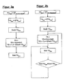
- FIG. 2a illustrates by means of a signal flow diagram a method for controlling the dry content
- FIG. 2b illustrates by means of a signal flow diagram a method for controlling the dry content
- FIGS. 3a and 3b illustrated by diagrams of the operation of the solution according to the invention
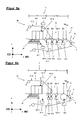
- FIGS. 4a and 4b illustrate exemplified possible configurations of a forming unit following the immobility point suitable for use of the method according to the invention with reference to a section of this
- FIG. 5a and 5b illustrate by way of example further possible configurations of a forming unit following the immobility point suitable for use of the method according to the invention with reference to a section of this
- Figures 6a and 6b illustrate by way of example possible third configurations of a forming unit following the immobility point suitable for use of the method according to the invention with reference to a section of this
- Figure 7a a schematic sectional view of a first embodiment of a dewatering device in the form of a Siebsaugwalze for the forming unit according to the invention
- FIG. 7b a schematic sectional view of a second embodiment of a dewatering device in the form of a Siebsaugwalze for the forming unit according to the invention
- FIG. 8a a schematic sectional view of a first embodiment of a dewatering device in the form of a high vacuum suction for the forming unit according to the invention
- FIG. 8b a schematic sectional view of a second embodiment of a dewatering device in the form of a high vacuum suction for the forming unit according to the invention.
- FIGS. 1a and 1b illustrate in schematic highly simplified representation based on an exemplary embodiment of a forming unit 1 and a control / regulating system 4, the basic principle of a method according to the invention for optimizing the energy balance within the forming unit 1 in a machine 2 for producing webs, in particular in the form of fibrous webs F in shape of paper, cardboard or tissue webs.
- FIG. 1a Schematically shown in simplified form FIG. 1a to a forming unit 1, which is preceded by a headbox 3, via which a pulp suspension FS of the forming unit 1 is supplied.
- a coordinate system is applied to the forming unit 1.
- the X-direction describes the direction of the guidance of the pulp suspension FS and thus the provided within the machine 2 for the production of fibrous web passage direction for the material web formed therefrom, which is also referred to as the machine direction MD.
- the direction perpendicular to this in the same horizontal plane describes the Y-direction, which corresponds to the cross-machine direction MD and is referred to as the CD direction.
- the Z direction perpendicular to both aforementioned directions describes the vertical direction.
- the pulp suspension FS is guided on at least one endlessly circulating screen belt 11.1, in the case shown at least over a partial area between two endlessly rotating screen belts 11.1 and 11.2, filtered and thickened and from reaching a so-called immobility point IP in the subsequent compression zone VZ compacted.
- the forming unit 1 in the form of a hybrid former comprises in the illustrated case, by way of example, three dewatering sections S1 to S3, which are connected in series and one after the other be traversed by the pulp suspension FS. These are structured differently.
- the first dewatering section S1 in the direction of passage forms a so-called predewatering zone 10, the subsequent dewatering section S2 is referred to as twin-wire zone 12, while the dewatering section S3 forms a post-dewatering section 13.
- the screen belt 11.1 is part of all drainage routes S1 to S3.
- drainage devices E1 to En are at least indirectly effective on the pulp suspension FS.
- a breast roll 14 is provided following the headbox 3 in the first endlessly circulating wire 11.1.
- the shot of the pulp suspension FS takes place directly on a, in a horizontal plane arranged Siebtisch as dewatering unit E2, which is supported by the sieve belt 11.1 formed Langsieban ever.
- the dewatering takes place via the dewatering section S1 and thus the pre-dewatering zone 10.
- the fibrous suspension FS is further guided and dewatered via the second dewatering section S2, which is formed by the twin-wire zone 12.
- the screen belt 11.1 is guided together with a further, second, endlessly circulating screen belt 11.2 in the form of a top wire belt over part of its circulation path to form the dewatering path S2.
- at least one dewatering device E3 is arranged, which is effective on at least one of the screen belts, preferably both screen belts 11.1 and 11.2 and the fibrous suspension FS guided therebetween.
- the separation between the first and the second screen belt 11.1 and 11.2 is carried out downstream of the dewatering device E3, which can be provided to support the separation of suction, for example in the form of curved vacuum cleaner or drainage E3 is provided with a correspondingly trained suction zone.
- the dewatering device E3 consists of a arranged in the sieve belt 11.2 dewatering box 15 and in the screen belt 11.1 in the region of the extension of the dewatering 15 in Siebumlaufraum Siebbands 11.2 viewed formation box 16.
- the dewatering box 15 and the formation box 16 contain so-called formation strips, preferably in the Formation box 16 contained formation strips 16.1 to 16.n are mounted on the inner surface of the screen belt 11.1 against this pressed.
- the individual formation strips 16.1 to 16.n in the formation box 16 are preferably individually, in groups or can be pressed together.
- the formation strips 16.1 to 16.n are preferably guided individually and viewed one behind the other in the wire direction, preferably arranged parallel to one another and extend over the machine width.
- the drainage box 15 forms the drainage device E3.2, the formation box 16 the drainage device E3.1.
- the contact pressure of the formation strips 16.1 to 16.n via an adjusting device 9.31. Drainage box 15 and / or formation box 16 are further evacuated, wherein the aspiration in the direction of extension in the machine direction MD viewed over a suction zone or a plurality of successively connected and individually or in groups can be controlled suction zones.
- the immobility point IP sets for the fibers in the pulp suspension FS. This marks in the machine direction MD, the location at which the fibers of the pulp suspension FS are aligned due to the dewatering that now no longer change their orientation and remain in position to each other, with a further action of drainage facilities only for further drainage under Compaction leads, which is why the point of immobility subsequent functional area is referred to as compression zone VZ.
- This local area is provided within the dewatering section S2 and extends across the width of the forming unit 1.
- the post-dewatering zone 13 Downstream of the twin-wire zone 12 is the post-dewatering zone 13, which is connected in series and successively contains the dewatering devices E4, En-1 and En, where En forms the last dewatering device upstream of the transfer area 5.
- the individual drainage devices E4 to En may preferably be in the form of suction devices.
- the post-dewatering zone 13 is formed by the first screen belt 11.1.
- the forming unit 1 thus comprises at least one, preferably a plurality of drainage devices E1 to En acting in series or in parallel.
- the resulting fibrous web F has a dry content TG, which is referred to as the final dry content of the forming unit 1. This is usually specified and corresponds to the set dry content TG at the end of the forming unit 1.
- TG dry content
- the investment conditions such as speed of the machine for producing fibrous webs F and the selected dewatering E1 to En and their operating parameters can for a particular pulp suspension, ie a Fasoffoffsuspension with certain properties, such as composition, consistency, etc. theoretically a maximum final dry content TG max at the end of the forming unit 1, in particular in the transfer area 5 or before this be achieved following the last drainage device En.
- the inventors have recognized that slightly max of TG deviating lower dry content TG target in the exit region 17 of the forming unit 1, that is in or before the transfer region 5 after the last dewatering device En also be achieved if the performance of each drainage facilities, in particular those of the last in Passage direction arranged drainage device arranged upstream of E and the immobility point IP, here E4 to En-1 with n element of the natural numbers does not correspond to their theoretically available maximum power, so that the theoretically maximum available drainage capacity at the last drainage device En can be fully utilized.
- a targeted dry content TG target of the fibrous web F for the outflow region 17 of the forming unit 1 is predefined, which ranges from about 0.1 to 5%, preferably 0.1 to 3%, very particularly preferably 0.1 to 2%. deviates from the theoretically maximum achievable and substance-dependent dry content TG max under plant conditions.
- This is set as setpoint X set -TG target .
- the current is adjusting the actual value X Is target TG at the outlet 17 of the forming unit 1 is detected by means of a device 7 for the at least indirect detection of the dry content of TG at least indirectly characteristic.
- This device 7 is preferably assigned directly to the web guide in the outlet region 17 of the forming unit 1 and is designed in the simplest case as a sensor.
- the desired value is processed in a control and / or regulating device 8 and set by driving at least one, preferably at least the, the last drainage device En directly upstream drainage device En-1.
- the control and / or regulating device 8 with the adjusting device or the adjusting devices 9.1 to 9.n-1 of each, the last arranged within the forming unit 1 in the direction of flow of the pulp suspension FS drainage device En upstream drainage devices E1 to En-1 coupled.
- These are preferably controlled as a function of the goal to be achieved dry content X target TG target in dependence of the actually existing actual value in such a way that the actual value X Is TG target corresponds to the target value X set target TG.
- the control takes place in such a way that the dewatering power at the drainage device upstream of the dewatering device En and downstream of the immobility point IP En-1 or the other upstream drainage devices E4 to En-1 is lowered, so that each set at the outlet of these individual drainage E4 to En-1 a lower dry content than when fully exploiting the drainage at the individual drainage E4 to En-1.
- the individual drainage devices E4 to En-1 arranged after the immobility point IP and before the last drainage device En act as setting devices of a control / regulation 4 of the target dry content TG target .
- FIG. 1b exemplifies the input and output variables at the, associated with the forming unit 1 control and / or regulating device 8.
- the input X is at least the target value for the targeted dry content X target -TG goal , in addition to a control the actual value X actual - TG Goal .
- the last drainage device En While maintaining the conditions at the last drainage device En, in particular setting the maximum drainage capacity at this by controlling the associated adjusting device 9.n to form a corresponding manipulated variable Y9.n the other manipulated variables Y9.4 and / or Y9.n-1 are determined and the actuators 9.4 and / or 9.n-1 driven.
- FIG. 2a illustrates the basic principle of the method according to the invention on the basis of a signal flow diagram.
- This shows the knowledge or the determination of the maximum dry content TG max , which can be achieved theoretically within the forming unit 1 with the available drainage devices E1 to En in their combination in application with optimum utilization of the theoretically available drainage capacity P max .
- a target dry content TG target to be achieved is set for the operation of the forming unit 1, which is determined as a function of TG max .
- the target dry content TG target is set as target value X target -TG target of a controller, preferably a controller.
- FIG. 2a exemplifies only the control.
- an activation of at least one of the last drainage device En of the forming unit 1 upstream drainage device En-1 to En-x and thus a specification of the manipulated variables Y9.n-1, x f ( X target -TG target ), where x corresponds to the maximum number of drainage devices E within the compression zone VZ.
- FIG. 2b illustrates the integration of the controller according to the invention in a control, wherein in addition to the setpoint specification X target -TG target the current actual value Xist-TG target is continuously determined and the individual manipulated variables Y9.n-1, x for controlling the last drainage device upstream drainage facilities En-1 to En-x are formed.
- the last drainage device En in the direction of flow is operated with the maximum possible drainage capacity.
- the manipulated variable Y9.n for driving is constant, ie remains unchanged or is set according to the maximum power.
- the drainage behavior at the drainage devices upstream of the last drainage device En-1, x can be controlled and regulated in such a way that they are lowered with respect to their drainage performance and the maximum possible dewatering effect is achieved with the last possible drainage effect with the last drainage device En becomes.
- the dry content TG of the pulp suspension FS or of the fibrous web F present at the respectively considered dewatering device E initially increases very rapidly with the suction time. Due to the exponential characteristics of the drainage behavior, however, the slope of the dewatering intensity decreases progressively, that is, the dry content increase per time interval is reduced.
- the dry content TG asymptotically approaches over the theoretically achievable absolutely dry content TG ⁇ at this dehydrator E after endless dry season, especially on suction time. This corresponds to the dry content TG ⁇ , which is achieved at infinite suction time at the individual drainage device. Changes in the input dry matter TG E-one therefore do not significantly affect the initial dry matter content TG E- out.
- the single dewatering device is operated in the prior art with maximum dewatering power, wherein over the operating time t operation , which corresponds to the exposure time a theoretically maximum dry content TG max is achieved.
- the Inventors have now recognized that the behavior can be optimally exploited to operate the entire system described more effectively and in particular more energy efficient by a less than the theoretically maximum achievable dry content TG max is set as the target dry content TG target to reach, which still one permissible minimum dry content at the outlet from the forming unit 1 corresponds. This is controlled, preferably adjusted.
- FIG. 3b 3 illustrates a concrete example of a dry content development in a forming unit 1 within a sheet compacting zone VZ comprising by way of example a two-zone suction suction roll in the form of a combined dewatering device with a subsequent dewatering device En in the form of a high vacuum suction device.
- the individual suction zones of the suction sieve are referred to as drainage devices E4 and E5.
- the guide speed of the fibrous web F is exemplified 2000 m / min.
- the dry content TG E4,5-a before the sieve suction roll with the individual suction zones E4, E5 is constantly 8%.
- the resulting characteristic is indicated in the diagram by II.
- the vacuum level in the first zone and thus at E4 is 25 kPa, at the second dewatering device E5 55 kPa.
- the achievable initial dry matter content TG E4, E5-Aus and thus input dry matter content TG En-one at the drainage facility En is reduced to 13.3% compared to I.
- the large drop in dry content at the suction sieve roller is partly compensated by the following drainage device En. With the same performance, the drainage performance of En En increases, thereby allowing better lubrication between the screen belt and the drainage device En.
- FIGS. 4a and 4b illustrate exemplified by means of sections of a former unit 1 arrangements of the individual drainage elements E1 to En, the immobility point IP and the site for the target dry content TG goal .
- a dewatering unit E1 of two on both sides of the sides of the fibrous suspension FS leading screen belts 11.1, 11.2 becoming effective drainage E1.1 and E1.2 wherein one of the two drainage E1.1, E1.2 is designed as a drainage box 15, to which a vacuum can be applied and the other second dewatering E1.2 with elastic formation strips 16.1 to 16.n, which are effective at the carrying of the pulp suspension FS side facing away from the screen belt 11.2, is executed.
- the dewatering device E1 After passing through the dewatering device E1, the immobility point IP is reached and the fibrous web F arising from the pulp suspension FS is conveyed via individual further dewatering devices E2 in the form of a suction device, E3 in the form of a suction sieve and En-1 in the form of a suction device and the last suction device arranged in the direction of flow En drained.
- the dewatering behavior at the individual dewatering elements E2 and / or E3 and / or En-1 can be controlled to set the target dry content TG, in order to achieve a lower input dry content at the inlet to the last dewatering element En.
- FIG. 4b illustrates the FIG. 4b an embodiment according to FIG. 4a in which the drainage element En-1 was omitted.
- the control is essentially on the now the last drainage device
- FIG. 5a illustrates a section of a forming unit 1 with twin-wire zone 12 and subsequent Nachentskyss proceedingsszone 13, wherein the twin-wire zone 12 is at least partially shown, comprising here a dewatering unit E1 from an upper dewatering E1.2 and arranged in the lower wire belt 11.1 drainage E1.1 with strip-shaped Elements 16.1 to 16.n for introducing pressure pulses in the guided between the two endlessly rotating screen belts 11.1 and 11.2 pulp suspension FS.
- a drainage device E2 in the form of a suction device also follows.
- the dewatering devices E3, En-1 and En with their adjusting devices 9.3, 9.n-1 and 9.n are arranged.
- the control of the drainage behavior takes place here mainly via the control of either the drainage device En-1 and / or E3 and / or E2.
- FIG. 5b illustrates the FIG. 5b an alternative embodiment of the formation of a twin-wire zone 12, in which, following the dewatering device E1 from E1.2 in the form of a dewatering box 15 and E1.1 in the form of a formation box 16 in the screen belt 11.1 a suction device is arranged, comprising two suction zones forming the dewatering devices E2, E3 and spaced therefrom after separation of the two sieve bands 11.1, 11.2 in the fibrous web guiding wire 11.1 the dewatering device En-1 and then a Siebsaugwalze as dewatering En.To achieve the target dry content TG target behind the last dewatering element En in the form of Siebsaugwalze the input dry content is controlled at this by controlling the dewatering behavior on at least one of the individual dewatering elements E2 to En-1.
- FIG. 6a and 6b illustrate exemplified further embodiments of a forming unit 1, comprising a dewatering E1.1 in the form of a suction sieve suction and arranged on the bottom wire drainage E1.2 and then spaced therefrom arranged drainage elements E2 to En, wherein E2 to E4 are formed by individual suction devices, while En-1 is formed by a suction roll and En in turn by a suction device.
- the FIG. 6b illustrates an alternative embodiment with a reduced number of drainage devices E2 and E3 compared FIG. 6a wherein the dewatering device E1.2 has a different number of Siebsaugzonen.
- FIG. 7a shows a schematic sectional view of a first embodiment of a dewatering device E3 in the form of a Siebsaugwalze for the invention and in the FIGS. 4a, 4b . 6a and 6b illustrated and described forming unit. 1
- the suction sieve shown and well-known to those skilled in the art has, purely by way of example, two suction zones which, based on the FIG. 3b denoted by E4 and E5. Of course, it can also have more than two suction zones.
- the two immediately adjacent suction zones E4 and E5 are separated from each other by means of a common main partition 18.
- the mutual limitation of the respective suction zone E4 and E5 is effected by means of a respective movable secondary partition 19.4 and 19.5. If the respective side partition wall 19.4 and 19.5 is arranged in its end position, then each of the two suction zones E4 and E5 has an open area of 100%.
- the respective open area of the individual suction zone E4 and E5 can be set in a range of 100% to 0%.
- the movement (arrow) of the respective secondary dividing wall 19.4 and 19.5 can take place in a known manner by means of a respective actuating device 9.4 and 9.5 which can be acted upon by the control and / or regulating device.
- the two side walls 19.4 and 19.5 are also after one shown movement dashed lines, wherein the first suction zone E4 then still has an open area of about 30% and the second suction zone E5 then still has an open area of about 50%.
- FIG. 7b shows a schematic sectional view of a second embodiment of a dewatering device E3 in the form of a Siebsaugwalze for the invention and in the FIGS. 4a, 4b . 6a and 6b illustrated and described forming unit. 1
- the suction sieve shown and well-known to those skilled in the art has, purely by way of example, two suction zones which, based on the FIG. 3b denoted by E4 and E5. Of course, it can also have more than two suction zones.
- the two immediately adjacent suction zones E4 and E5 are separated from each other by means of a common main partition 18.
- the mutual limitation of the respective suction zone E4 and E5 is carried out by means of a respective side partition 19.4 and 19.5.
- the respective suction zone E4 and E5 has a maximum open area of 100%.
- a cover plate 20.4 and 20.5 is provided for each of the two suction zones E4 and E5, by means of which the open area of the associated suction zone E4 and E5 can be reduced to 0%.
- the individual cover plate 20.4 and 20.5 is arranged inside the respective suction zone E4 and E5 movable (arrow).
- the movement (arrow) of the respective cover plate 20.4 and 20.5 can take place in a known manner by means of a respective actuatable by the control and / or regulating device 9.4 and 9.5.
- FIG. 8a shows a schematic sectional view of a first embodiment of a dewatering device E6 in the form of a high vacuum suction for the invention and in the FIGS. 1a . 4a, 4b . 5a, 5b . 6a and 6b illustrated and described forming unit. 1
- the illustrated and the expert well-known high-vacuum suction device has purely by way of example a suction zone E7, the top side with a guided sieve contacting suction pad 21 is provided.
- the suction pad 21 may be perforated, slotted or arbitrarily open structured in a known manner and it has a maximum open area of 100%.
- a cover plate 22.6 is provided, by means of which the open surface of the Saugerbelags 21 can be reduced to 0%.
- the cover plate 22.6 is arranged on the inside of the suction zone E7 movable (arrow). The movement (arrow) of the cover plate 22.6 can in a known manner by means of an actuatable by the control and / or regulating device 9.4. respectively
- FIG. 8b shows a schematic sectional view of a second embodiment of a dewatering device E6 in the form of a high vacuum suction for the invention and in the FIGS. 1a . 4a . 4b . 5a . 5b . 6a and 6b illustrated and described forming unit. 1
- the illustrated and well-known to the skilled high vacuum cleaner has purely by way of example a suction zone E7, which is provided on the upper side with a guided sieve touching the suction pad 21.
- the suction pad 21 may be perforated, slotted or arbitrarily open structured in a known manner and it has a maximum open area of 100%.
- at least one means 24 for reducing the open areas is provided for each opening 23 of the sucker pad.
- the means 24 may, for example, be a bellows 25, which may be acted upon by an actuating device 9.4 which can be acted upon by the control and / or regulating device. can be acted upon.
- the open area of the Saugerbelags 21 can be reduced to 0%.
Landscapes
- Paper (AREA)
Claims (14)
- Procédé pour optimiser le bilan énergétique d'une unité de façonnage (1) dans une machine (2) de fabrication de bandes de matière fibreuse (F), notamment des bandes de papier, de carton ou de tissu, selon lequel une suspension de matière fibreuse (FS) introduite dans l'unité de façonnage (1) par le biais d'une caisse de tête (3), après avoir atteint le point d'immobilité (IP), est amenée par le biais d'au moins deux dispositifs d'assèchement (E2 à En) à l'intérieur d'une zone de compression (VZ) adjacente au point d'immobilité vers une zone de transfert (17) à une unité fonctionnelle (6) rattachée,
caractérisé en ce
qu'une valeur de consigne pour une siccité cible (Xsoll-TGZiel) à régler est prédéfinie en fonction d'une siccité maximale (TGmax) pouvant être obtenue théoriquement sous les conditions de l'installation à proximité de la zone de transfert (17) de la bande de matière fibreuse (F) à l'unité fonctionnelle (6) disposée à la suite sur la base des éléments d'assèchement (E1 à En) présents, ladite valeur de consigne étant choisie de telle sorte que celle-ci est inférieure à la siccité maximale (TGmax) pouvant être obtenue théoriquement, mais toutefois égale ou supérieure à une siccité minimale nécessaire à proximité de la zone de transfert (17), et en ce que la siccité cible (TGZiel) est commandée en réduisant la siccité d'entrée (TGE-ein) au niveau de l'un des derniers dispositifs d'assèchement (En) à l'intérieur de la zone de compression (VZ), disposés dans le sens du guidage de la suspension de matière fibreuse (FS). - Procédé selon la revendication 1, caractérisé en ce que la siccité cible (TGZiel) est commandée en réduisant la siccité d'entrée (TGE-ein) au niveau du dispositif d'assèchement (En) à l'intérieur de la zone de compression (VZ) qui est disposé en dernier dans le sens du guidage de la suspension de matière fibreuse (FS).
- Procédé selon la revendication 1 ou 2, caractérisé en ce que la siccité d'entrée (TGE-ein) au niveau d'au moins l'un des derniers dispositifs d'assèchement (En) disposés dans le sens du guidage de la suspension de matière fibreuse (FS) ou du dernier dispositif d'assèchement (En) est réglée en commandant la puissance d'assèchement au niveau d'au moins l'un des ces dispositifs d'assèchement (E2 à En-1) disposés en amont à l'intérieur de la zone de compression (VZ).
- Procédé selon l'une des revendications précédentes, caractérisé en ce que les paramètres de fonctionnement d'un dispositif d'assèchement (E2 à En-1, En-1, x) disposé en amont du dernier dispositif d'assèchement (En) disposé dans le sens du guidage de la suspension de matière fibreuse (FS) ou du dernier dispositif d'assèchement (En) sont réglés de telle sorte que celui-ci fonctionne avec une puissance d'assèchement inférieure à celle possible au maximum.
- Procédé selon l'une des revendications précédentes, caractérisé en ce que la siccité cible (TGZiel) est régulée.
- Procédé selon l'une des revendications précédentes, caractérisé en ce qu'une valeur réelle de la siccité cible (Xist-TGZiel) derrière le dernier élément d'assèchement (En) est déterminée continuellement ou périodiquement, comparée avec la valeur de consigne (Xsoll-TGZiel) et les dispositifs actionneurs individuels (9.1-9.n-1) des dispositifs d'assèchement (E1 à En-1, En-1, x) individuels sont commandés en fonction de la différence.
- Procédé selon l'une des revendications précédentes, caractérisé en ce qu'une siccité cible (TGZiel) est prédéfinie, laquelle diffère de la siccité maximale (TGmax) pouvant être obtenue théoriquement d'une plage de 0,1 à 5 %, notamment de préférence de 0,1 à 3 %, et de manière toute préférentielle de 0,1 à 2 %.
- Procédé selon l'une des revendications précédentes, caractérisé en ce que le dispositif d'assèchement (E2 à En-1, En-1, x) disposé en amont de l'un des derniers dispositifs d'assèchement (En) disposés dans le sens du guidage de la suspension de matière fibreuse (FS) ou du dernier dispositif d'assèchement (En) à l'intérieur de la zone de compression (VZ) est réalisé sous la forme d'un dispositif d'aspiration, notamment d'un dispositif d'aspiration fixe ou d'un rouleau aspirant égoutteur rotatif.
- Procédé selon l'une des revendications précédentes, caractérisé en ce que l'un des derniers dispositifs d'assèchement (En) disposés dans le sens du guidage de la suspension de matière fibreuse (FS) ou le dernier dispositif d'assèchement (En) est réalisé sous la forme d'un dispositif d'aspiration fixe, notamment d'un dispositif d'aspiration à vide poussé fixe, ou d'un rouleau aspirant égoutteur rotatif, notamment d'un rouleau aspirant égoutteur à vide poussé.
- Procédé selon l'une des revendications 8 ou 9, caractérisé en ce qu'au moins le vide pouvant être appliqué est réglable.
- Procédé selon l'une des revendications 8 à 10, caractérisé en ce que les dispositifs d'assèchement (E1-En, En-1, En-1, x) réalisés sous la forme d'un dispositif d'aspiration fixe ou d'un rouleau aspirant égoutteur rotatif comprennent au moins une, de préférence plusieurs zones d'aspiration (15.1, 15.2) orientées dans le sens de la machine (MD) et/ou transversalement par rapport au sens de la machine (MD), lesquelles peuvent être commandées individuellement, par groupes ou ensemble.
- Unité de façonnage (1) d'une machine de fabrication de bandes de matière fibreuse (F), comprenant au moins une bande de filtration (11.1, 11.2) circulant sans fin qui soutient au moins indirectement une suspension de matière fibreuse (FS) et au moins deux dispositifs d'assèchement (En-1, En-1, x, En) connectés en série et disposés l'un derrière l'autre dans le sens de défilement de la suspension de matière fibreuse (FS) à l'intérieur d'une zone de compression (VZ),
caractérisée en ce
qu'il est prévu un système de commande et/ou de régulation (4), comprenant un dispositif de commande et/ou de régulation (8) qui est relié avec au moins un équipement (7) destiné à détecter au moins indirectement une grandeur qui caractérise au moins indirectement la siccité (Xist-TGZiel) de la bande de matière fibreuse (F) dans une zone de transfert (5) depuis l'unité de façonnage (1) à une unité fonctionnelle (6) disposée à la suite, un équipement pour indiquer une valeur de consigne d'une siccité cible à régler (Xsoll-TGZiel) et au moins indirectement avec les dispositifs actionneurs (9.1 à 9.n-1) d'un dispositif d'assèchement (E2 à En-1, En-1, x) individuel disposé en amont de l'un des derniers dispositifs d'assèchement ou du dernier dispositif d'assèchement (En) à l'intérieur de la zone de compression (VZ) et un générateur de grandeur de commande pour former les grandeurs de commande (Y9.1 à Y9.n) des dispositifs d'assèchement (E1 à En) individuels. - Unité de façonnage (1) selon la revendication 12, caractérisée en ce que le dispositif de commande et/ou de régulation (8) est couplé avec les dispositifs actionneurs (9.1 à 9.n) des dispositifs d'assèchement (E1 à En) individuels.
- Unité de façonnage (1) selon la revendication 12 ou 13, caractérisée en ce que les dispositifs d'assèchement (E1 à En) individuels sont réalisés sous la forme de l'un des dispositifs d'assèchement suivantes :- dispositif d'aspiration, notamment dispositif d'aspiration fixe ou rouleau aspirant égoutteur rotatif ;- caisson de façonnage comprenant au moins une zone d'aspiration et des barres de façonnage fixes ou compressibles ;- barres de façonnage ; ou- élément d'assèchement arqué.
Applications Claiming Priority (2)
| Application Number | Priority Date | Filing Date | Title |
|---|---|---|---|
| DE102008040688A DE102008040688A1 (de) | 2008-07-24 | 2008-07-24 | Verfahren zur Optimierung der Energiebilanz in Formiereinheiten in Maschinen zur Herstellung von Faserstoffbahnen und Formiereinheit |
| PCT/EP2009/059406 WO2010010109A1 (fr) | 2008-07-24 | 2009-07-22 | Procédé d'optimisation du bilan énergétique des unités de formage dans des machines de fabrication de bandes de matières fibreuses, ainsi qu'unité de formage |
Publications (2)
| Publication Number | Publication Date |
|---|---|
| EP2313552A1 EP2313552A1 (fr) | 2011-04-27 |
| EP2313552B1 true EP2313552B1 (fr) | 2013-01-09 |
Family
ID=41129184
Family Applications (1)
| Application Number | Title | Priority Date | Filing Date |
|---|---|---|---|
| EP09780911A Not-in-force EP2313552B1 (fr) | 2008-07-24 | 2009-07-22 | Procédé d'optimisation du bilan énergétique des unités de formage dans des machines de fabrication de bandes de matières fibreuses, ainsi qu'unité de formage |
Country Status (5)
| Country | Link |
|---|---|
| US (2) | US8349136B2 (fr) |
| EP (1) | EP2313552B1 (fr) |
| CN (1) | CN102105635B (fr) |
| DE (1) | DE102008040688A1 (fr) |
| WO (1) | WO2010010109A1 (fr) |
Families Citing this family (7)
| Publication number | Priority date | Publication date | Assignee | Title |
|---|---|---|---|---|
| DE102008040688A1 (de) * | 2008-07-24 | 2010-01-28 | Voith Patent Gmbh | Verfahren zur Optimierung der Energiebilanz in Formiereinheiten in Maschinen zur Herstellung von Faserstoffbahnen und Formiereinheit |
| US20150292158A1 (en) * | 2012-09-28 | 2015-10-15 | Voith Patent Gmbh | Method for controlling the formation of a fiber web of a fiber or paper producing process |
| DE102016120647B4 (de) * | 2016-10-28 | 2018-07-26 | Voith Patent Gmbh | Verfahren zum Betreiben einer Maschine zur Herstellung einer Faserstoffbahn |
| DE102019103254A1 (de) * | 2019-02-11 | 2020-08-13 | Voith Patent Gmbh | Geregelte Bahnvergautschung |
| FI131544B1 (en) | 2023-08-28 | 2025-06-17 | Valmet Technologies Oy | Method for regulating negative pressure in a forming section and forming section with a control system for regulating the negative pressure of the forming section |
| FI131577B1 (en) | 2023-08-28 | 2025-07-11 | Valmet Technologies Oy | Method for regulating negative pressure in a forming section and forming section with a control system for regulating negative pressure in the forming section |
| CN119849212B (zh) * | 2025-03-19 | 2025-07-01 | 北京市城市规划设计研究院 | 管道覆盖率和管道排水能力评估方法及装置 |
Family Cites Families (44)
| Publication number | Priority date | Publication date | Assignee | Title |
|---|---|---|---|---|
| US3040807A (en) * | 1959-11-04 | 1962-06-26 | Industrial Nucleonics Corp | Moisture balance correction system |
| US3649444A (en) * | 1969-05-15 | 1972-03-14 | Westvaco Corp | Moisture control system including control of pulp flow to a paper machine headbox in response to moisture measurement |
| DE4002304A1 (de) | 1990-01-26 | 1991-08-14 | Escher Wyss Gmbh | Former in einer papiermaschine |
| DE4005420C2 (de) * | 1990-02-21 | 1995-06-08 | Voith Gmbh J M | Doppelsiebformer |
| DE4019884A1 (de) * | 1990-06-22 | 1992-01-09 | Voith Gmbh J M | Leiste zur nachgiebigen stuetzung eines siebbandes |
| DE4141607C2 (de) * | 1991-12-17 | 1996-04-25 | Voith Gmbh J M | Doppelsiebformer |
| US6039838A (en) * | 1995-12-29 | 2000-03-21 | Kimberly-Clark Worldwide, Inc. | System for making absorbent paper products |
| US5825653A (en) * | 1997-03-14 | 1998-10-20 | Valmet Corporation | Method for overall regulation of a former of a paper machine or equivalent |
| US6087837A (en) * | 1996-12-13 | 2000-07-11 | Honeywell-Measurex | Compact high resolution under wire water weight sensor array |
| US5853543A (en) * | 1997-01-27 | 1998-12-29 | Honeywell-Measurex Corporation | Method for monitoring and controlling water content in paper stock in a paper making machine |
| JP3664857B2 (ja) * | 1997-09-05 | 2005-06-29 | 三菱重工業株式会社 | 抄紙機ツインワイヤフォーマの脱水機器 |
| FI974327L (fi) * | 1997-11-25 | 1999-05-26 | Valmet Automation Inc | Menetelmä ja laitteisto paperin ominaisuuksien säätämiseksi |
| FI974328L (fi) * | 1997-11-25 | 1999-05-26 | Valmet Automation Inc | Menetelmä ja laitteisto paperin ominaisuuksien säätämiseksi |
| DE19803591A1 (de) * | 1998-01-30 | 1999-08-05 | Voith Sulzer Papiertech Patent | Doppelsieb-Former |
| US6168687B1 (en) | 1998-04-24 | 2001-01-02 | Honeywell-Measurex Corporation | System and method for sheet measurement and control in papermaking machine |
| US6086716A (en) * | 1998-05-11 | 2000-07-11 | Honeywell-Measurex Corporation | Wet end control for papermaking machine |
| US6274002B1 (en) | 1998-06-23 | 2001-08-14 | Wilbanks International, Inc. | Papermaking machine with variable dewatering elements including variable pulse turbulation blades adjusted by computer control system in response to sensors of paper sheet characteristics |
| CA2276095A1 (fr) * | 1998-06-23 | 1999-12-23 | Dean A. Rulis | Appareil de fabrication du papier avec elements de deshydratation variables ajustes par commande informatique en reponse aux capteurs de caracteristiques des feuilles de papier |
| US6375799B1 (en) * | 1999-01-28 | 2002-04-23 | Voith Sulzer Papiertechnik Patent Gmbh | Process and apparatus for producing a fibrous material web |
| US6264796B1 (en) * | 1999-07-13 | 2001-07-24 | The Mead Corporation | Headbox diffuser |
| WO2001036744A1 (fr) * | 1999-11-17 | 2001-05-25 | Astenjohnson, Inc. | Monture de la lame dans la section de formation d'une machine a deux toiles |
| CN1208515C (zh) * | 1999-12-15 | 2005-06-29 | 麦特索纸业公司 | 多层纸或纸板幅的成形装置和方法 |
| DE60033124T2 (de) * | 1999-12-16 | 2007-11-15 | Metso Paper, Inc. | Entwässerungsleiste für eine Papiermaschine |
| DE10022110B4 (de) * | 2000-05-08 | 2007-10-25 | Dieter Ronnenberg | Beeinflussung eines Bahneigenschafts-Profiles mittels mindestens eines Schallfeldes |
| FI107943B (fi) * | 2000-06-12 | 2001-10-31 | Metso Paper Inc | Menetelmä ja säätöjärjestely formerin vedenpoistoprofiilin hallitsemiseksi |
| DE10051802A1 (de) * | 2000-10-18 | 2002-04-25 | Voith Paper Patent Gmbh | Lamelle eines Stoffauflaufs einer Papier-, Karton- oder Tissuemaschine |
| FI109299B (fi) * | 2001-01-22 | 2002-06-28 | Metso Paper Inc | Kaksiviiraformeri |
| DE10106684A1 (de) * | 2001-02-14 | 2002-08-29 | Voith Paper Patent Gmbh | Lamelle eines Stoffauflaufs einer Papier-, Karton- oder Tissuemaschine |
| DE10106731A1 (de) * | 2001-02-14 | 2002-08-22 | Voith Paper Patent Gmbh | Doppelsiebformer zur Herstellung einer Faserstoffbahn aus einer Faserstoffsuspension |
| DE10109413A1 (de) * | 2001-02-27 | 2002-09-05 | Voith Paper Patent Gmbh | Verfahren und Vorrichtung zur Verbesserung der Eigenschaften einer in einer Blattbildungseinrichtung hergestellten Faserstoffbahn |
| DE20104380U1 (de) * | 2001-03-13 | 2001-06-28 | Voith Paper Patent GmbH, 89522 Heidenheim | Doppelsiebformer |
| FI20012175A7 (fi) * | 2001-11-09 | 2003-05-10 | Metso Paper Automation Oy | Menetelmä ja laitteisto viiraosan toiminnan säätämiseksi |
| DE50201952D1 (de) * | 2002-01-24 | 2005-02-10 | Heinz Bartelmuss | Einrichtung zur Einstellung der Lage einer Abstreifleiste |
| FI111173B (fi) * | 2002-05-03 | 2003-06-13 | Metso Paper Inc | Menetelmä paperirainan laadun hallitsemiseksi |
| FI20020890A7 (fi) * | 2002-05-10 | 2003-11-11 | Antti Niemi | Menetelmä ja laitteisto vesirajan määrittämiseksi ja vesirajaan perustuvaksi ohjaamiseksi Fourdrinier-paperikoneessa |
| DE10257293A1 (de) | 2002-12-07 | 2004-09-09 | Voith Paper Patent Gmbh | Vorrichtung zur Herstellung einer Faserstoffbahn |
| DE10342769A1 (de) * | 2003-09-16 | 2005-04-21 | Voith Paper Patent Gmbh | System zur computergestützten Messung von Qualitäts- und/oder Prozessdaten |
| DE102005035558A1 (de) * | 2005-07-29 | 2007-02-01 | Voith Patent Gmbh | Papiermaschine mit einem Pressspalt und Verfahren zum Einstellen des Feuchtequerprofils einer Papierbahn |
| DE102005038424A1 (de) * | 2005-08-12 | 2007-02-15 | Voith Patent Gmbh | Verfahren zur Herstellung einer Faserstoffbahn und Doppelsiebformer zur Durchführung des Verfahrens |
| DE102006059308A1 (de) * | 2006-12-15 | 2008-06-19 | Voith Patent Gmbh | Verfahren und Vorrichtung zur Bestimmung der Feuchte einer laufenden Materialbahn |
| DE102008000267A1 (de) * | 2008-02-11 | 2009-08-20 | Voith Patent Gmbh | Verfahren zur Entwässerung und Entwässerungsvorrichtung |
| DE102008040688A1 (de) * | 2008-07-24 | 2010-01-28 | Voith Patent Gmbh | Verfahren zur Optimierung der Energiebilanz in Formiereinheiten in Maschinen zur Herstellung von Faserstoffbahnen und Formiereinheit |
| DE102008040948A1 (de) * | 2008-08-01 | 2010-02-04 | Voith Patent Gmbh | Doppelsiebformer für eine Maschine zur Herstellung einer Faserstoffbahn |
| CN102203345B (zh) * | 2008-10-21 | 2013-07-17 | 阿斯顿约翰逊公司 | 具有多个排水底板的双织物成形部 |
-
2008
- 2008-07-24 DE DE102008040688A patent/DE102008040688A1/de not_active Withdrawn
-
2009
- 2009-07-22 EP EP09780911A patent/EP2313552B1/fr not_active Not-in-force
- 2009-07-22 CN CN2009801288348A patent/CN102105635B/zh not_active Expired - Fee Related
- 2009-07-22 WO PCT/EP2009/059406 patent/WO2010010109A1/fr not_active Ceased
-
2010
- 2010-08-18 US US12/858,943 patent/US8349136B2/en not_active Expired - Fee Related
-
2011
- 2011-12-21 US US13/333,712 patent/US8323452B2/en not_active Expired - Fee Related
Also Published As
| Publication number | Publication date |
|---|---|
| WO2010010109A1 (fr) | 2010-01-28 |
| CN102105635B (zh) | 2012-12-05 |
| EP2313552A1 (fr) | 2011-04-27 |
| US8349136B2 (en) | 2013-01-08 |
| CN102105635A (zh) | 2011-06-22 |
| US8323452B2 (en) | 2012-12-04 |
| DE102008040688A1 (de) | 2010-01-28 |
| US20110024069A1 (en) | 2011-02-03 |
| US20120145346A1 (en) | 2012-06-14 |
Similar Documents
| Publication | Publication Date | Title |
|---|---|---|
| EP2313552B1 (fr) | Procédé d'optimisation du bilan énergétique des unités de formage dans des machines de fabrication de bandes de matières fibreuses, ainsi qu'unité de formage | |
| DE4218595C2 (de) | Maschine zur Herstellung einer Papierbahn | |
| WO2011151239A2 (fr) | Machine pour produire une bande de papier, en particulier une bande de papier pour sac | |
| EP1225270A2 (fr) | Procédé pour le conditionnement d' une bande en mouvement | |
| EP0780513B1 (fr) | Procédé pour fabrication d'une bande | |
| DE69429390T2 (de) | Formiervorrichtung für mehrschichtige Faserbahnen | |
| EP0837181B1 (fr) | Section de pressage | |
| DE19604675C2 (de) | Maschine zur Herstellung einer Faserstoffbahn | |
| DE10326304A1 (de) | Verfahren und Vorrichtung zur Herstellung einer Tissuebahn | |
| DE19756203A1 (de) | Naßpartie und Verfahren zur Herstellung einer Faserstoffbahn | |
| EP2227593A1 (fr) | Système et procédé pour réguler au moins un paramètre de qualité d'une bande de matériau, en particulier d'une bande de matière fibreuse dans une machine à papier et/ou à carton | |
| EP1478806A1 (fr) | Dispositif de lissage | |
| DE2826158A1 (de) | Verfahren und maschine zur herstellung von faserbahnen | |
| EP0824159A2 (fr) | Procédé et dispositif pour la fabrication d'une bande fibreuse | |
| DE19631637A1 (de) | Pressenanordnung | |
| EP1398412B1 (fr) | Section de formage à deux toiles pour la production d'une bande fibreuse | |
| DE19980188B9 (de) | Verfahren und Vorrichtung zur Formierung von Faserplatten | |
| EP1426488A1 (fr) | Dispositif de formation d'une bande fibreuse | |
| AT214255B (de) | Maschine zur Erzeugung von Papier | |
| WO2025160604A1 (fr) | Procédé de fonctionnement d'une installation de production de papier kraft | |
| WO2025160602A1 (fr) | Dispositif de compression, installation et procédé de production de papier kraft | |
| AT527975A1 (de) | Anlage und Verfahren zur Herstellung von Kraftpapier mit einer Bypassanordnung | |
| DE102008043358A1 (de) | Verfahren und Vorrichtung zur Bahnüberführung | |
| DE102010031447A1 (de) | Verfahren und Maschine zur Herstellung einer Faserstoffbahn | |
| EP2204491A1 (fr) | Procédé et dispositif de réglage du profil transversal d'humidité dans la zone de la partie tamis |
Legal Events
| Date | Code | Title | Description |
|---|---|---|---|
| PUAI | Public reference made under article 153(3) epc to a published international application that has entered the european phase |
Free format text: ORIGINAL CODE: 0009012 |
|
| 17P | Request for examination filed |
Effective date: 20110224 |
|
| AK | Designated contracting states |
Kind code of ref document: A1 Designated state(s): AT BE BG CH CY CZ DE DK EE ES FI FR GB GR HR HU IE IS IT LI LT LU LV MC MK MT NL NO PL PT RO SE SI SK SM TR |
|
| AX | Request for extension of the european patent |
Extension state: AL BA RS |
|
| RIN1 | Information on inventor provided before grant (corrected) |
Inventor name: ESPER, MARCO Inventor name: SCHMIDT-ROHR, VOLKER Inventor name: KAUFMANN, OLIVER Inventor name: SCHMALENBACH, MORITZ Inventor name: RUEHL, THOMAS |
|
| DAX | Request for extension of the european patent (deleted) | ||
| REG | Reference to a national code |
Ref country code: DE Ref legal event code: R079 Ref document number: 502009006008 Country of ref document: DE Free format text: PREVIOUS MAIN CLASS: D21F0009000000 Ipc: D21G0009000000 |
|
| GRAP | Despatch of communication of intention to grant a patent |
Free format text: ORIGINAL CODE: EPIDOSNIGR1 |
|
| RIC1 | Information provided on ipc code assigned before grant |
Ipc: D21G 9/00 20060101AFI20120905BHEP |
|
| GRAS | Grant fee paid |
Free format text: ORIGINAL CODE: EPIDOSNIGR3 |
|
| GRAA | (expected) grant |
Free format text: ORIGINAL CODE: 0009210 |
|
| AK | Designated contracting states |
Kind code of ref document: B1 Designated state(s): AT BE BG CH CY CZ DE DK EE ES FI FR GB GR HR HU IE IS IT LI LT LU LV MC MK MT NL NO PL PT RO SE SI SK SM TR |
|
| REG | Reference to a national code |
Ref country code: GB Ref legal event code: FG4D Free format text: NOT ENGLISH |
|
| REG | Reference to a national code |
Ref country code: CH Ref legal event code: EP Ref country code: AT Ref legal event code: REF Ref document number: 592840 Country of ref document: AT Kind code of ref document: T Effective date: 20130115 |
|
| REG | Reference to a national code |
Ref country code: IE Ref legal event code: FG4D Free format text: LANGUAGE OF EP DOCUMENT: GERMAN |
|
| REG | Reference to a national code |
Ref country code: DE Ref legal event code: R096 Ref document number: 502009006008 Country of ref document: DE Effective date: 20130307 |
|
| PG25 | Lapsed in a contracting state [announced via postgrant information from national office to epo] |
Ref country code: SI Free format text: LAPSE BECAUSE OF FAILURE TO SUBMIT A TRANSLATION OF THE DESCRIPTION OR TO PAY THE FEE WITHIN THE PRESCRIBED TIME-LIMIT Effective date: 20130109 |
|
| REG | Reference to a national code |
Ref country code: NL Ref legal event code: VDEP Effective date: 20130109 |
|
| REG | Reference to a national code |
Ref country code: LT Ref legal event code: MG4D |
|
| PG25 | Lapsed in a contracting state [announced via postgrant information from national office to epo] |
Ref country code: LT Free format text: LAPSE BECAUSE OF FAILURE TO SUBMIT A TRANSLATION OF THE DESCRIPTION OR TO PAY THE FEE WITHIN THE PRESCRIBED TIME-LIMIT Effective date: 20130109 Ref country code: NO Free format text: LAPSE BECAUSE OF FAILURE TO SUBMIT A TRANSLATION OF THE DESCRIPTION OR TO PAY THE FEE WITHIN THE PRESCRIBED TIME-LIMIT Effective date: 20130409 Ref country code: SE Free format text: LAPSE BECAUSE OF FAILURE TO SUBMIT A TRANSLATION OF THE DESCRIPTION OR TO PAY THE FEE WITHIN THE PRESCRIBED TIME-LIMIT Effective date: 20130109 Ref country code: IS Free format text: LAPSE BECAUSE OF FAILURE TO SUBMIT A TRANSLATION OF THE DESCRIPTION OR TO PAY THE FEE WITHIN THE PRESCRIBED TIME-LIMIT Effective date: 20130509 Ref country code: ES Free format text: LAPSE BECAUSE OF FAILURE TO SUBMIT A TRANSLATION OF THE DESCRIPTION OR TO PAY THE FEE WITHIN THE PRESCRIBED TIME-LIMIT Effective date: 20130420 Ref country code: BG Free format text: LAPSE BECAUSE OF FAILURE TO SUBMIT A TRANSLATION OF THE DESCRIPTION OR TO PAY THE FEE WITHIN THE PRESCRIBED TIME-LIMIT Effective date: 20130409 |
|
| PG25 | Lapsed in a contracting state [announced via postgrant information from national office to epo] |
Ref country code: PL Free format text: LAPSE BECAUSE OF FAILURE TO SUBMIT A TRANSLATION OF THE DESCRIPTION OR TO PAY THE FEE WITHIN THE PRESCRIBED TIME-LIMIT Effective date: 20130109 Ref country code: PT Free format text: LAPSE BECAUSE OF FAILURE TO SUBMIT A TRANSLATION OF THE DESCRIPTION OR TO PAY THE FEE WITHIN THE PRESCRIBED TIME-LIMIT Effective date: 20130509 Ref country code: GR Free format text: LAPSE BECAUSE OF FAILURE TO SUBMIT A TRANSLATION OF THE DESCRIPTION OR TO PAY THE FEE WITHIN THE PRESCRIBED TIME-LIMIT Effective date: 20130410 Ref country code: NL Free format text: LAPSE BECAUSE OF FAILURE TO SUBMIT A TRANSLATION OF THE DESCRIPTION OR TO PAY THE FEE WITHIN THE PRESCRIBED TIME-LIMIT Effective date: 20130109 Ref country code: LV Free format text: LAPSE BECAUSE OF FAILURE TO SUBMIT A TRANSLATION OF THE DESCRIPTION OR TO PAY THE FEE WITHIN THE PRESCRIBED TIME-LIMIT Effective date: 20130109 |
|
| PG25 | Lapsed in a contracting state [announced via postgrant information from national office to epo] |
Ref country code: HR Free format text: LAPSE BECAUSE OF FAILURE TO SUBMIT A TRANSLATION OF THE DESCRIPTION OR TO PAY THE FEE WITHIN THE PRESCRIBED TIME-LIMIT Effective date: 20130109 |
|
| PG25 | Lapsed in a contracting state [announced via postgrant information from national office to epo] |
Ref country code: EE Free format text: LAPSE BECAUSE OF FAILURE TO SUBMIT A TRANSLATION OF THE DESCRIPTION OR TO PAY THE FEE WITHIN THE PRESCRIBED TIME-LIMIT Effective date: 20130109 Ref country code: DK Free format text: LAPSE BECAUSE OF FAILURE TO SUBMIT A TRANSLATION OF THE DESCRIPTION OR TO PAY THE FEE WITHIN THE PRESCRIBED TIME-LIMIT Effective date: 20130109 Ref country code: RO Free format text: LAPSE BECAUSE OF FAILURE TO SUBMIT A TRANSLATION OF THE DESCRIPTION OR TO PAY THE FEE WITHIN THE PRESCRIBED TIME-LIMIT Effective date: 20130109 Ref country code: CZ Free format text: LAPSE BECAUSE OF FAILURE TO SUBMIT A TRANSLATION OF THE DESCRIPTION OR TO PAY THE FEE WITHIN THE PRESCRIBED TIME-LIMIT Effective date: 20130109 Ref country code: SK Free format text: LAPSE BECAUSE OF FAILURE TO SUBMIT A TRANSLATION OF THE DESCRIPTION OR TO PAY THE FEE WITHIN THE PRESCRIBED TIME-LIMIT Effective date: 20130109 |
|
| PGFP | Annual fee paid to national office [announced via postgrant information from national office to epo] |
Ref country code: DE Payment date: 20130722 Year of fee payment: 5 Ref country code: FI Payment date: 20130711 Year of fee payment: 5 |
|
| PLBE | No opposition filed within time limit |
Free format text: ORIGINAL CODE: 0009261 |
|
| STAA | Information on the status of an ep patent application or granted ep patent |
Free format text: STATUS: NO OPPOSITION FILED WITHIN TIME LIMIT |
|
| PG25 | Lapsed in a contracting state [announced via postgrant information from national office to epo] |
Ref country code: CY Free format text: LAPSE BECAUSE OF FAILURE TO SUBMIT A TRANSLATION OF THE DESCRIPTION OR TO PAY THE FEE WITHIN THE PRESCRIBED TIME-LIMIT Effective date: 20130109 |
|
| 26N | No opposition filed |
Effective date: 20131010 |
|
| PG25 | Lapsed in a contracting state [announced via postgrant information from national office to epo] |
Ref country code: IT Free format text: LAPSE BECAUSE OF FAILURE TO SUBMIT A TRANSLATION OF THE DESCRIPTION OR TO PAY THE FEE WITHIN THE PRESCRIBED TIME-LIMIT Effective date: 20130109 |
|
| REG | Reference to a national code |
Ref country code: DE Ref legal event code: R097 Ref document number: 502009006008 Country of ref document: DE Effective date: 20131010 |
|
| BERE | Be: lapsed |
Owner name: VOITH PATENT G.M.B.H. Effective date: 20130731 |
|
| PG25 | Lapsed in a contracting state [announced via postgrant information from national office to epo] |
Ref country code: MC Free format text: LAPSE BECAUSE OF FAILURE TO SUBMIT A TRANSLATION OF THE DESCRIPTION OR TO PAY THE FEE WITHIN THE PRESCRIBED TIME-LIMIT Effective date: 20130109 |
|
| REG | Reference to a national code |
Ref country code: CH Ref legal event code: PL |
|
| GBPC | Gb: european patent ceased through non-payment of renewal fee |
Effective date: 20130722 |
|
| REG | Reference to a national code |
Ref country code: IE Ref legal event code: MM4A |
|
| REG | Reference to a national code |
Ref country code: FR Ref legal event code: ST Effective date: 20140331 |
|
| PG25 | Lapsed in a contracting state [announced via postgrant information from national office to epo] |
Ref country code: LI Free format text: LAPSE BECAUSE OF NON-PAYMENT OF DUE FEES Effective date: 20130731 Ref country code: BE Free format text: LAPSE BECAUSE OF NON-PAYMENT OF DUE FEES Effective date: 20130731 Ref country code: GB Free format text: LAPSE BECAUSE OF NON-PAYMENT OF DUE FEES Effective date: 20130722 Ref country code: CH Free format text: LAPSE BECAUSE OF NON-PAYMENT OF DUE FEES Effective date: 20130731 |
|
| PG25 | Lapsed in a contracting state [announced via postgrant information from national office to epo] |
Ref country code: FR Free format text: LAPSE BECAUSE OF NON-PAYMENT OF DUE FEES Effective date: 20130731 |
|
| PG25 | Lapsed in a contracting state [announced via postgrant information from national office to epo] |
Ref country code: IE Free format text: LAPSE BECAUSE OF NON-PAYMENT OF DUE FEES Effective date: 20130722 |
|
| REG | Reference to a national code |
Ref country code: DE Ref legal event code: R119 Ref document number: 502009006008 Country of ref document: DE |
|
| PG25 | Lapsed in a contracting state [announced via postgrant information from national office to epo] |
Ref country code: FI Free format text: LAPSE BECAUSE OF NON-PAYMENT OF DUE FEES Effective date: 20140722 Ref country code: DE Free format text: LAPSE BECAUSE OF NON-PAYMENT OF DUE FEES Effective date: 20150203 |
|
| REG | Reference to a national code |
Ref country code: DE Ref legal event code: R119 Ref document number: 502009006008 Country of ref document: DE Effective date: 20150203 |
|
| PG25 | Lapsed in a contracting state [announced via postgrant information from national office to epo] |
Ref country code: SM Free format text: LAPSE BECAUSE OF FAILURE TO SUBMIT A TRANSLATION OF THE DESCRIPTION OR TO PAY THE FEE WITHIN THE PRESCRIBED TIME-LIMIT Effective date: 20130109 |
|
| PG25 | Lapsed in a contracting state [announced via postgrant information from national office to epo] |
Ref country code: TR Free format text: LAPSE BECAUSE OF FAILURE TO SUBMIT A TRANSLATION OF THE DESCRIPTION OR TO PAY THE FEE WITHIN THE PRESCRIBED TIME-LIMIT Effective date: 20130109 Ref country code: MT Free format text: LAPSE BECAUSE OF FAILURE TO SUBMIT A TRANSLATION OF THE DESCRIPTION OR TO PAY THE FEE WITHIN THE PRESCRIBED TIME-LIMIT Effective date: 20130109 |
|
| PG25 | Lapsed in a contracting state [announced via postgrant information from national office to epo] |
Ref country code: LU Free format text: LAPSE BECAUSE OF NON-PAYMENT OF DUE FEES Effective date: 20130722 Ref country code: MK Free format text: LAPSE BECAUSE OF FAILURE TO SUBMIT A TRANSLATION OF THE DESCRIPTION OR TO PAY THE FEE WITHIN THE PRESCRIBED TIME-LIMIT Effective date: 20130109 Ref country code: HU Free format text: LAPSE BECAUSE OF FAILURE TO SUBMIT A TRANSLATION OF THE DESCRIPTION OR TO PAY THE FEE WITHIN THE PRESCRIBED TIME-LIMIT; INVALID AB INITIO Effective date: 20090722 |
|
| REG | Reference to a national code |
Ref country code: AT Ref legal event code: MM01 Ref document number: 592840 Country of ref document: AT Kind code of ref document: T Effective date: 20140722 |
|
| PG25 | Lapsed in a contracting state [announced via postgrant information from national office to epo] |
Ref country code: AT Free format text: LAPSE BECAUSE OF NON-PAYMENT OF DUE FEES Effective date: 20140722 |